Embed Size (px)
Citation preview
Transportation Research Record 1043
It is clear from both of these figures that a substantial increase in longitudinal cracking can be obtained by reducing the standard deviation (see the examples in Figures 4 and 5 shown by a dotted line for a depth ratio = 0. 75). This indicates that reasonable control of the quality of this construction material (concrete), pavement thickness, and saw-cut depth, all combined, can contribute to a reasonable saw-cut depth.
CONCLUSIONS
The results of this study can be summarized as follows:
1. The development of longitudinal cracks in a saw-cut groove can be explained by a model using the concepts of variability in concrete strength and thickness of pavement sections.
2. The model developed for this study is sensitive to the construction quality of pavement. An improvement in construction quality can result in reduction of saw-cut depths. The reliability of longitudinal cracks (being confined to saw-cut groove) is also improved. This can save construction costs as well as future maintenance and repair costs.
3. Figures 3-5 show that it is possible to induce any desired amount of longitudinal cracking along the saw-cut groove if an appropriate saw-cut depth is provided.
4. The aggregates used in concrete affect the development of longitudinal cracks along a saw-cut
13
groove. This finding is based on a study of two aggregates (river gravel and limestone).
ACKNOWLEDGMENTS
The authors are pleased to acknowledge the combined efforts and support of the Center for Transportation Research at the University of Texas at Austin and the Texas State Department of Highways and Public Transportation, in cooperation with the FHWA, U.S. Department of Transportation.
REFERENCE
1. J.R. Benjamin and C.A. Cornell. Probability Statistics and Decision for Civil Engineers. McGraw-Hill Book Company, New York, 1970.
The contents of this paper reflect the views of the authors, who are responsible for the facts and the accuracy of the data presented herein. The contents do not necessarily reflect the official views or policies of the Federal Highway Administration. This paper does not constitute a standard, specification, or regulation.
Publication of this paper sponsored by Committee on Rigid Pavements.
Westergaard Solutions Reconsidered
A. M. IOANNIDES, M. R. THOMPSON, and E. J. BARENBERG
ABSTRACT
The pioneering analytical work of Harold Malcom Westergaard (1888-1950) has been at the heart of slab-on-grade pavement design since the 1920s. Every code of practice published since then makes reference to the "Westergaard solutions." These solutions are only available for three particular loading conditions (interior, edge, and corner) and assume a slab of infinite or semi-infinite dimensions. Since their first appearance, beginning in the early 1920s, Westergaard equations have often been misquoted or misapplied in subsequent publications. To remedy this situation, a reexamination of these solutions using the finite element method is described in this paper. A number of interesting results are presented: (a) Several equations ascribed to Westergaard in the literature are erroneous, usually as a result of a series of typographical errors or misapplications, or both. The correct form of these equations and their limitations have now been conclusively established. (b) Westergaard' s original equation for edge stress is incorrect. The long-ignored equation given in his 1948 paper should be used instead. (c) Improved expressions for maximum corner loading responses have been developed. (d) Slab size requirements for the development of Westergaard responses have also been established.
14
The pioneering analytical work of Harald Malcom Westergaard (1888-1950) has been at the heart of slab-on-grade pavement design since the 1920s. Every code of practice published since then makes reference to the "Westergaard solutions." These solutions are only available for three particular loading conditions (interior, edge, and corner) and assume a slab of infinite or semi-infinite dimensions. In practice, the slab size required for the development of Westergaard responses is determined empirically, Several investigators, however, have noted repeatedly that although the Westergaard solution agreed fairly well with their observations for the interior loading condition, it failed to give even a close estimate of the response in the cases of edge and corner loading. The time-honored Westergaard solutions deserve a thorough reexamination using the tool of finite element analysis now available.
The highlights of an effort to reevaluate the Westergaard solutions (1) are presented. The form, theoretical background, limitations, and applicability of these equations have been examined, and what are considered to be the most accurate formulas are presented herein. Several empirical adjustments to the Westergaard solutions are also considered, and slab size requirements for the development of Westergaard responses are established.
The basic tool for this study is the ILLI-SLAB finite element computer program developed and exlensively used at the University of Illinois (~). The ILLI-SLAB model is based on classical medium-thick plate theory, and employs the 4-noded, 12-degree-offreedom plate-bending element, known in finite element literature as ACM or RPB12 (3). The Winklertype subgrade assumed by Westergaarcf is modeled as a uniform, distributed subgrade through an equivalent mass formulation (_!) •
INTERIOR LOADING
As defined by Westergaard, this is the case of a wheel load at a "considerable distance from the edges," with pressure "assumed to be uniformly distributed over the area of a small circle with radius a" (2_). After an extensive literature survey and comparisons with finite element results (6), the following interior loading equations are considered to be in their most general form.
Maximum bending stress, cri
Ordinary theory BSIOT= j[3P(l +µ)]/27rh 2} [Qn (2£/a)
+ 0.5 - 'Y] + BSI20T (la)
Special theory BSIST = j[3P(l + µ)] /27Th2 f [Qn (2£/b)
+ 0.5 - 'Y] + BSI2ST (lb)
For square BSISQ = j [3P(l + µ)] /27rh 2 f [Qn (2£/c')
+ 0.5 - 'Yl + BSilSQ (le)
Supplomcnlary, <1 2 BSI20T = j [3P(l + µ)] /64h2} [(a/£)2
] (Id) (ordinnry theory)
Supplementary, <12 BSI2ST = j [3P(l + µ)] /64h2} [(b/£)2
] (le) (special theory)
Supplementary, a2 BSI2SQ = j [3P(l + µ)] /64h2} [(c' /£)2] (If)
(for square)
Maximum deflection, .Si
Circle DEFIC = (P/8kQ2 ) j 1 + (l/27T) [Qn (a/2£)
+ 'Y- 5/4] (a/£)2 f (lg)
Transportation Research Record 1043
where
P total applied load; E slab Young's modulus; µ slab Poisson's ratio; h slab thickness; k modulus of subqrade reaction; a = radius of circular load; c = side length of square load;
£' {Eh'/[12(1 - µ 2 )k]} which is radius of relative stiffness;
b [ (l.6a 2 + h 2)
112 J - 0.675h if a < 1. 724h
~ a if a > l.724h; c' (err/4-1;21/2)c; and
y Euler's constant (= 0.577 215 664 90).
These equations have been incorporated into WESTER, a computerized compendium of closed-form solutions for slabs on grade, developed in the course of this research (!) •
Equation la follows from Equation 50 given in 1939, with the term [£n (U/a) - y] replacing the term [1n (2£/ya)] used by Westergaard (]). Note that the symbol y as used in Equation la is the Euler constant, whereas Westergaard uses this symbol to denote the antilog of the Euler constant.
Equation la also includes supplementary stress, a2 , first derived by Westergaard in 1939. This is calculated according to Equation ld, which is the same as Equation 6 in "Stresses in Concrete Runways of Airports" (].). This additional term was introduced to account for the effect of the finite size of the loaded area and is "satisfactorily applicable when a does not exceed 1" (7). Its contribution is usually small, but it is i~cluded because of its rigorous analytical nature. The effect of the size of the loaded area will be discussed further hereafter.
Equation lb employs Westergaard's "special theory," first proposed in 1926, in which radius b replaces Lhe true radius, a, of the loaded area. This was introduced to account for the effect of shear stresses in the vicinity of the load, which is neglected in the "ordinary theory" of medium-thick plates. As Westergaard stated, "the effect of the thickness of the slab is equivalent to a rounding off of the peak in the diagrams of moments" (~), To determine the relation among h, a, and b, Westergaard (5) performed "numerical computations ••• in accordance with an analysis which is due to A. Nadai." Results were fitted with a hyperbola, the equation of which may be written in the form presented earlier, "which is suitable for numerical calculations" (5). The validity of Westergaard's semiempirical adjustment and of the resulting "special theory" has been debated by various investigators [see, for example, Scott (~)], but a full discussion of this issue would be beyond the scope of this paper. The authors recommend, however, using "ordinary theory" when comparisons with finite element results are made.
To obtain the interior stress in the case of a square loaded area, radius a is replaced in Equation 1-c by a constant, c', related to the length of the side of the square, c, as follows:
c' = (e"/4 - 1 /2%) c = 0.573804 ... c
The resulting expression is not stated explicitly by Westergaard, but follows directly from his theory (9,10). Timoshenko and Woinowsky-Krieger (11) ,provid-;- a theoretical justification for this substitution by showing that, loaded by the same total load P, a square side c and a circle radius a give the same maximum interior stress.
Ioannides et al.
In 1948 Westergaard presented an equation for the stress under an elliptical loaded area [Equation 3 in "New Formulas for Stresses in Concrete Pavements of Airfields" (10) I. Setting both axes of the ellipse to a, th~ equation can be compromised with Equation la provided that the following assumption is made.
Qn 2 + 1/2-'Y ~ l/4Qn 12(1-µ 2)
For µ = 0.15, this assumption gives
0.6159316 ""0.6155374
This indicates that the term 0.6159 in Equation 9 in "Stresses in Concrete Pavements Computed by Theoretical Analysis" (5) is a truncated form of the term involving Euler 1 s constant, not slab Poisson's ratio, µ. Equation la is, therefore, more general than the 1948 equation.
Equation lg follows from Equation 51 in "Stresses in Concrete Runways of Airports" (7) , described previously, with the introduction of-Euler's constant. This form is more general than the one obtained from Equation 5 in "New Formulas for Stresses in Concrete Pavements of Airfields" (10), which makes the approximation noted in the previous paragraph.
Westergaard also presented an equation for supplementary stress, a3, to account for "the effects of a plausible redistribution" of subgrade reactions (12, 7). This was a semiempir ical adjustment to reduce calculated stresses so that they agreed better with the 1932 Arlington tests (13). Bergstrom et al. (14) note that "it appears advisable to neglect a3in design," because it is difficult to evaluate and causes considerable reduction in stress. Further discussions of this term are presented by Bradbury (15) and Kelley (16) •
Slab Si~e Requirements for the Development of Interior Loading Westergaard Responses
As mentioned earlier, the closed-form Westergaard solutions assume a slab of infinite dimensions, al-
300
"' 200 ~
0 0
~ ~ VI Q)
3:
I I I I I I VDeflection
\ \ \ \ \
\
' 'o
15
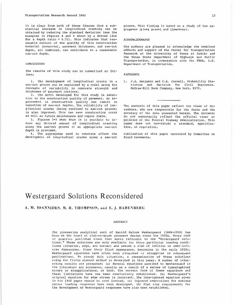
though in practice empirical guidelines have been developed for the least slab dimension, L, required to achieve the Westergaard "infinite slab" condition. In this section, analyses will be presented to establish similar guidelines using the finite element method. A slab with a radius of relative stiffness, 9-, of 23.16 in. was used with a mesh fineness ratio (2a/h) of 1.8. An earlier study (&_) indicated that this ratio of element size, 2a, divided by slab thickness, h, must be about 0.8 for 98 percent accuracy.
ILLI-SLAB results from this investigation are shown in Figure 1. Both maximum deflection and bending stress converge to large slab values. The convergence of deflection is from above, indicating that a smaller slab settles more than a bigger one in a "punch-like" fashion. Bending stress converges from below, as expected. The rate of convergence, defined as the slab size at which the solution is essentially that for an infinite slab, is different for deflection (L/9- = 8. 0) than for bending stress (L/9- = 3.5). Surprisingly, deflection appears to be much more sensitive to slab size changes for (L/9-) values of less than 3, because of the previously mentioned punch-like effect. The limit value approached by maximum deflection is the Westergaard solution (Equation lg). The value to which bending stress converges when slab size is expanded is slightly lower than Westergaard' s (Equation la) due to the coarseness of the mesh used.
Effect of Size of Loaded Area
In his attempt to develop equations for a loaded area of finite size, Westergaard used an approach in which a solution for a point load is first derived. Then, the loaded area is split into a number of small subareas, and each subarea is replaced by a statically equivalent point load acting at its center. A summation is performed over these subareas. In the limit of refinement, this summation tends to an exact integration (17). Westergaard suggested that his equations were valid for any size of loaded
k = 12 h .
+ = 0.216 ...... _
....... _______ ··-<)----~
100
Bending Stress
0 3 5 6 10 12 15 18
Slab Size, L(ft)
1.6 3.1 4.0 6,2 9.3 L
T FIGURE 1 Effect of slab size on maximum interior loading responses.

16
area and that his "New Formulas" (10) assume that "the average width and length of the footprint of the tire is greater than the thickness of the slab in all significant cases."
Losberg (18) showed that the stress and deflection equatioM presented by Westergaard are only the first one or two terms of a rapidly converging infinite series. Westergaard's supplementary stress, a2, mentioned previously, for example, is an additional term of this series. The rate of convergence can be expected to vary depending on, among other things, the size of the loaded area.
Timoshenko and Woinowsky-Krieger (11) state that the equations apply only when the radius of the loaded area is "small in comparison with t ." Scott (~) attributes this restriction to the fact that "in the derivation of the equation a term of approximate value 0.1 a 2/R. 2 was omitted." This cannot be the real cause of the restriction imposed by Timoshenko and Woinowsky-Kr ieger, because in most cases (even when the radius of the loaded area, a, is not "small in comparison with R.") this term is, indeed, negligible.
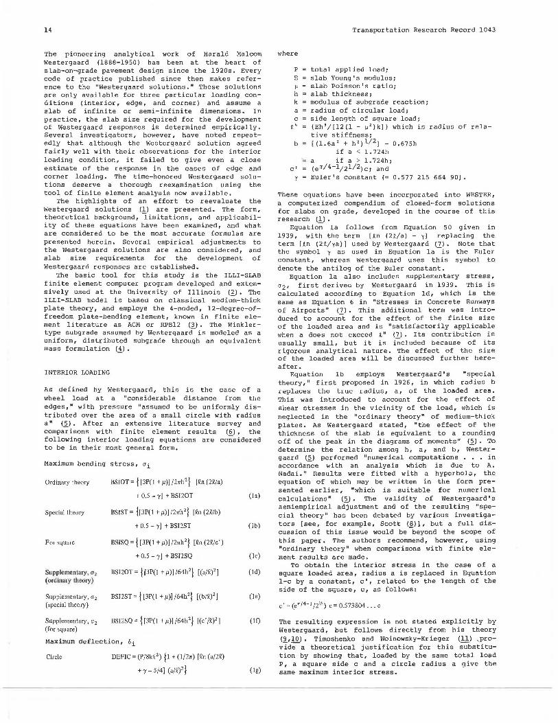
In this study the effect of the size of the loaded area was investigated using the finite element method. To eliminate s lab s i ze , mesh fineness, and element aspect ratio effects, a large (L/R. = 9.33) and fine (2a/h = 0.6) mesh, which consisted of square elements (aspect ratio = 1.0), was used. The results are plotted in Figure 2.
It is observed that Westergaard stress values (Equation la) agree with finite element results for a loaded area whose side length, c (if square), is about 0.2 times the radius of relative stiffness, R.; if the load is circular, its radius, a, must be about O.lR.. As (c/R.) or (a/R.) increase, finite element stresses become progressively higher than Westergaard's. Therefore the consequences of Westergaard's truncation, mentioned previously, must be borne in mind when attempting such comparisons. The results in Figure 2 also suggest an effect related to the internal finite element discretization of the applied load. This is discussed in more detail elsewhere <.!l·
EDGE LOADING
Westergaard defined edge loading as the case in which "the wheel load is at the edge, but at a con-
115
11 0
~ 0 0
"' ~ 105 Q)
iii Q)
3:
~ 100
95
0. 1 0.2
Transportation Research Record 1043
siderable distance from any corner." The pressure is assumed to be "distributed uniformly over the area of a small semi-circle with the center at the edge" (~). Equations for a circular load at the edge were first presented in 1948 (10). The most general forms of the edge loading formulas follow.
Maximum bending stress, ae
Ordinary theory (semicircle)
Special theory (semicircle)
"New" formula (circle)
"New" formula (semicircle)
Simplified "new" formula (semicircle)
Simplified "new" formula (circle)
BSEWOT = 0.529 (1+ 0.54µ) (P/h2 ) [log 1 0 (Eh3
+ka~)- 0.71) (2a)
BSEWST = 0.529 (I + 0.54µ) (P/h2) [log 10 (Eh 3
+kb~)-0. 71 ] (2b)
BSEIC= [3(1 +µ)P/rr(3 +µ)h 2 ) jQn(Eh3 /100ka4)
+ 1.84 - 4 µ/3 + [(J - µ)/2 ]
+ 1.18 (I+ 2µ)(a/Q) f (2c)
BSEIS = [3(1 + µ)P/71(3 + µ)h 2 ) [Qn (Eh3 /!00ka~)
+ 3.84 - 4µ/3 + 0.5 (I + 2 µ) (a2/Q)) (2d)
BSELS = (-6P/h2) (I + 0.5 µ) [0.489 log1 o (a2/Q)
- 0.091 - 0.027 (a2/Q)] (2e)
BSELC = (-6P/h2 )(1 + 0,5µ) [0.489 log10 (a/.1')
- 0.012 - 0.063 (a/Q)) (21)
Maximum defl ection, 6e
Original formula DEFEW = (1 /6'h) (I + 0.4µ) (P/kQ2) (2g)
"New" formula DEFEIC = ( j P[(2 + l.2µ)v, ) f / [(Eh 3 k)y' J) [ l (circle) - (0.76 + 0.4µ) (a/Q)) (2h)
"N ewu formula DEFEJS =(j P[(2 + J.2µf'lf / [(Eh 3k)y, J) [ l (semicircle) - (0.323 + 0.17µ) (o2 /Q)) (2i)
Simplified "new" DE FELS= (1 /6'1' ) (I + 0.4µ) (P/kQ2) [ 1 formula (semicircle) - 0.323 (1 + 0.5µ) (a2 /.1')) (2j)
Simplified "new" DEFELC = (1/6"') (I+ 0.4µ) (P/kQ2 ) [l formula (circle) - 0.760 (1 + 0.5µ)(a/.1')) (2k)
2ha = 0.6
i = 9_33
0.3 0.4
c T
FIGURE 2 Effect of size of loaded area on maximum interior loading responses.
Ioannides et al.
where
a2 radius of semicircle, b 2 [(l.6a2 + h 2 ) 112J - 0.675h
if a 2 < 1. 724h a2 if a 2 > l.724h, and
other symbols are as defined for Equations 1 .
Equation 2a is identical to Equation 3 in "Analytical Tools for Judging Results of Structural Tests of Concrete Pavements" (g). Equation 2b employs the "special theory," which is also used for interior loading. In his 1948 paper, Westergaard (10) presented generalized solutions for maximum stress and deflection produced by elliptical and semielliptical loaded areas placed at a slab edge. Setting the lengths of both the major and minor semiaxes of the ellipse to a or a 2 leads to the corresponding solutions for a circle radius, a, or a semicircle radius, a2, given by Equations 2c and 2d.
Losberg (_~) presented simplified versions of these solutions by introducing "simplifications of the same type as Westergaard (19) himself introduced in his original formula for the case of edge loading" to eliminate the "complicated functional relationship" in which µ appears in these equations. Losberg (~) stated that his simplified equations "are well applicable, for the small µ-values here concerned." These are Equations 2e and 2f. Comparisons made during this study show that Losberg's simplified equations lead to results that are typically about 1 percent greater than those obtained by the general Equations 2c and 2d.
Equation 2g is Westergaard's original equation for edge deflection (~),and Equations 2h and 2i can be obtained from his 1948 paper (!Q), as indicated previously. The corresponding Losberg formulas (18) are given by Equations 2j and 2k. Setting the radius of the loaded area to zero, these formulas reduce to Equation 2g.
Alternative Westergaard Solutions
It was pointed out earlier, as well as by other investigators (14,18), that in the case of interior deflection and stress, as well as edge deflection, when the "new" formulas are specialized for a circular (or a semicircular) loaded area, they become identical to the corresponding original (5,12) equations. Results from this study show, however, that edge stresses calculated from the "new" formula are considerably different than those computed using the original formula. A number of alternative Westergaard solutions are considered in this section, in order to determine which one, if any, agrees best with finite element results.
TABLE 1 Alternative Westergaard Solutions
Deflection, De (mils) k h
17
In Table 1, five different Westergaard solutions are compared. In all of these, total applied load, P, and applied pressure, p, are matched in the Westergaard and finite element analyses. A previous study (6) confirmed that this is an appropriate representation of the square loaded area used in the finite element solution. The solutions given in Table 1 are code named WES! through WESV and were obtained using WESTER, which incorporates Equations 2.
The range of results in Table 1 is extremely wide. Therefore careful use of Westergaard' s theory cannot be overemphasized. The most obvious effect is that the "new" formulas typically lead to stresses 55 percent higher and deflections 8 percent lower than the values obtained using the original formulas (compare WESIV with WESIII).
A comparison of WESIV and WESV indicates that the semicircular load is more severe than the circular load (i.e., leads to higher stresses and deflections), as expected. If both the circular and the semicircular loads are reduced to an equivalent point load acting at the respective center of gravity, this expectation is shown to be justified because the center of gravity of the circle is further toward the interior of the slab than is that of the semicircle.
This argument also leads to the conclusion that the difference in response from a circular and a semicircular load should be fairly small and proportional to the difference in the distance between the respective centers of gravity and the slab edge. The difference between WESIV and WESV stresses is about 1 percent, and deflection difference is about 5 percent. These differences are much more compatible with expected values than is the stress difference obtained using the original equation (compare WESI and WESIII).
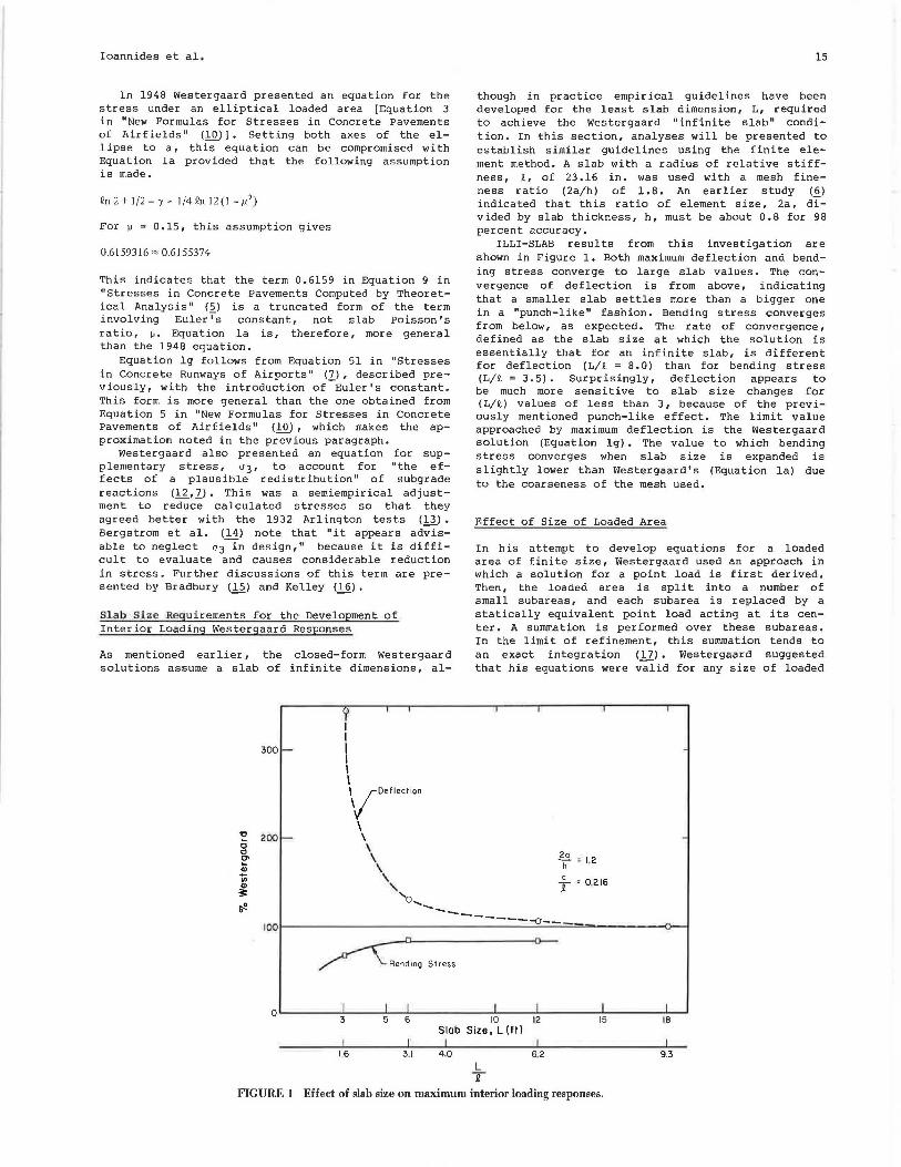
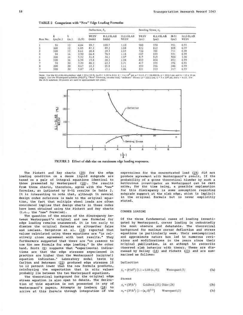
Table 2 gives a comparison of WESV, ILLI-SLAB, and H-51 results. The latter is a computerized version of the Pickett and Ray (20) chart for edge loading (21). Stresses exhibit almost perfect agreement even at low (L/~) values. Deflections are more sensitive to slab size effects, as shown in Figure 3. This graph shows that an (L/~) value of about 5.0 is required for the development of Westergaard stresses and about 8.0 is required for Westergaard deflections. The trends shown in Figure 3 are similar to those observed for the interior condition. Note, however, that the requirement for the development of maximum edge stress (L/l = 5.0) is higher than for maximum interior stress (L/~ = 3.5). The excellent agreement between ILLI-SLAB and H-51 results and the "new" formula confirms Losberg's observation that "the original formula for edge loading according to Westergaard (5) is, at least from a theoretical viewpoint, completely erroneous."
Bending Stress, De (psi)
Run No, (psi/in,) (in,) WES! WESI! WESIII WESIV WESV WES! WESII WESIII WESIV WESV
I 50 12 112.7 104,8 99 .7 758 661 638 992 980 2 200 12 56,4 50,8 47.3 638 541 519 831 822 3 500 12 35 ,7 31,3 28.4 559 462 440 726 720 4 50 16 73 ,2 Same as WES! 69.0 66.4 468 413 401 615 607 5 200 16 36,6 33.7 31.8 401 346 334 524 517 6 500 16 23.2 20.8 19.4 357 302 289 464 459 7 50 20 52.4 49.8 48.2 320 281 277 422 417 8 200 20 26.2 24.4 23.3 277 238 234 363 359 9 500 20 16.6 15.2 14.3 249 210 206 325 321
Note: WESI = Westergaard's original equations for circular "ordinary" theory, WESII = Westergaard's original equations for semicircular ''special" theory, WESIII = Westergaard's original equations for semicircular "ordinary" theory, WESIV ="New" formulas for semicircular "ordinary" theory, and WESV ="New" formulas for circular "ordinary" theory. See Table 2 for other parameters used.
18 Transportation Research Record 1043
TABLE 2 Comparison with "New" Edge Loading Formulas
Deflection, lie Bending Stress, Ge
k h WESV ILLI-SLAB ILLl-SLAB WESV ILLI-SLAB H-51 IL LI-SLAB Run No. (psi/in.) (in.) (L/Q) (mils) (mils) WESV (psi) (psi) (psi) WESV
I 50 12 4.84 99.7 109.7 1.10 980 974 951 0.99 2 200 12 6.85 47.3 49.2 1.04 822 813 808 0.99 3 500 12 8.61 28.4 29.3 1.03 720 705 711 0.98 4 50 16 3.90 66.4 78.5 1.18 607 593 591 0.98 5 iuu 16 5.52 31.8 34.1 1.07 517 515 504 1.00 6 500 16 6.94 19.4 20.2 1.04 459 454 452 0.99 7 50 20 3.30 48.2 63.3 1.31 417 395 396 0.95 8 200 20 4.67 23.3 25.8 1.11 359 356 348 0.99 9 500 20 5.87 14.3 15.1 1.06 321 319 317 0.99
Note: For the lLLI-SLAB solution: slab= 25 x 25 ft, (L/Jl) = 3.30 to 8.61, E = S x 106 psi,µ= 0,15, P = so,ooo lb, p = 222.2 psi, and A= 15 x 15 in . (edge). For the Westergaard solution (WESV), "New" formulas, circular load, "ordinary" theory: p = 222.2 psi, E = 5 x 10⁶ psi, andµ= 0.15, For the H-51 solution: SO points arc used to approximate tire print.
130
;;e 12.0
ID <l > _J (/) Ulw 110 _I_~ _J
::::!
100
2 3 4
( _!:._ l t
5
0
6 7 8
FIGURE 3 Effect of slab size on maximum edge loading responses_
The Pickett and Ray charts (20) for the edge loading condition on a dense liquid subgrade are based on a pair of integral equations identical to those presented by Westergaard (10). The results from these charts, therefore, agree with the "new" formulas, as indicated by H-51 results in Table 2. It is interesting to note that, although in several design codes reference is made to the original equation, the fact that multiple wheel loads are often considered implies that design charts in these codes have been obtained using the Pickett and Ray charts (i.e., the "new" formulas).
The question of the source of the discrepancy between Westergaard's original and new formulas for edge loading remains unanswered. It is too early to dismiss the original formulas as altogether false and useless. Bergstrom et al. (14) reported that values calculated using these equations are "in relatively close agreement with test results." They furthermore suggested that there are "no reasons to use the new formula for edge loading." On the other hand, Scott (.!!,) suggests that "experimental indications are that the edge stresses experienced in practice are higher than the Westergaard (original) equation indicates." Laboratory model tests by Carlton and Behrmann (22) produced edge stresses 10 to 12 percent lower than the new formula predicts, reinforcing the expectation that in situ values probably lie between the two Westergaard equations.
The theoretical background for the original edge stress equation is also open to debate. The derivation of this equation is not presented in any of Westergaard' s papers. Attempts by Losberg (18) to arrive at this formula through integration of the
expressions for the concentrated load (19) did not produce agreement with Westergaard's result. If the probability of a gross theoretical blunder by such a meticulous investigator as Westergaard can be cast aside, for the time being, a possible explanation for this discrepancy is some assumption regarding subgrade support at the slab edge, which is implicit in the original formula but is never explicitly stated.
CORNER LOADING
Of the three fundamental cas es of loading investigated by Westergaard, corner loading is undoubtedly the most obscure and debatable. The theoretical background for maximum corner deflection and stress equations is particularly weak. Their semiempir ical and approximate nature has led to numerous revisions and modifications in the years since their original publication, in an attempt to reconcile observed slab behavior with theory. These are discussed by Kelley (16) and Pickett (23) and are sum-marized as follows;-- -
Deflection
Westergaard (5)
Stress
<le= (3P/h2 ) Goldbeck (25), Older (26)
<le= (3P/h2) [1- (ai/Q)0 •6
] Westergaard (5)
(3a)
(3b)
(3c)
Ioannides et al.
Uc= (3P/h2) [I - (a/Q)0
·6
] Bradbury (15) (3d)
u0 = (3P/h2) [I - (ai/Q)l. 2
] Kelley (16), Teller and Sutherland(J3) (3e)
u0 = (3.2P/h2) [I - (ai/Q)] Spangler (28) (31)
u0 = (4.2P/h 2) (I - j [(a/Q)v'] /[0.925 + 0.22 (a/Q)] f) Pickett (23) (3g)
Distance to point of maximum stress along corner angle bisector
Westergaard (5) (3h)
where
a = radius of circular load tangent to both edges at corner and distance to point of action of resultant along corner angle bisector (21/2)a. See Equations 1 for other symbols.
In the early 1920s a short and simple piece of analytical work was heralded as "the most important single step in the investigation of the mechanics of road slabs" (£!). This was the first attempt to solve the problem of the "corner break" by two prominent engineers of the day working independently, A.T. Goldbeck of the Bureau of Public Roads and Clifford Older of the Illinois Highway Department. By assuming that in the corner region the slab acts as a cantilever of uniform strength (i.e., that in this region the subgrade reaction is negligible compared to the applied load), Equation 3b was proposed for the maximum stress, ac, due to a concentrated load, P, acting at the corner of a slab, of thickness h (3 .. ~ .. ~) •
A few years later, Westergaard (~) took up the problem again, trying to account for the effect of a load distributed over some area, the resultant of which could be represented by a point load P acting at a small distance a1 from the corner, along the bisector of the corner angle. Using a "simple approximate process" involving the use of the principle of minimum potential energy ( 27) he hoped to achieve an "improved approximation" of corner stress. Thus he first arrived at Equation 3a for corner deflection. He considered this equation "approximately applicable for plausible ranges of a1 and Jl" (presumably (a1/Jl) is not much greater than O. l] • From this, he obtained bending moments by integration and concluded that the maximum stress "would be represented with satisfactory accuracy" by Equation 3c. Furthermore, the distance to the point of maximum stress along the corner angle bisector was found to be given "roughly" by Equation 3h.
Equations for the Corner Loading Condition Based on the Finite Element Method
In this section, ILLI-SLAB is used to establish a set of equations that would accurately predict the response of a slab, in full contact with a Winkler foundation, to a single load distributed over a small area at its corner. Equations 3, proposed by previous investigators, suggest that, from a theoretical viewpoint, the parameters involved in the determination of slab response can be lumped into three nondimensional ratios to be investigated, namely, (6ckll 2/P) (ach'/P) and (a/Jl) or (a1/Jl) for a circular, or (c/Jl) for a square load.
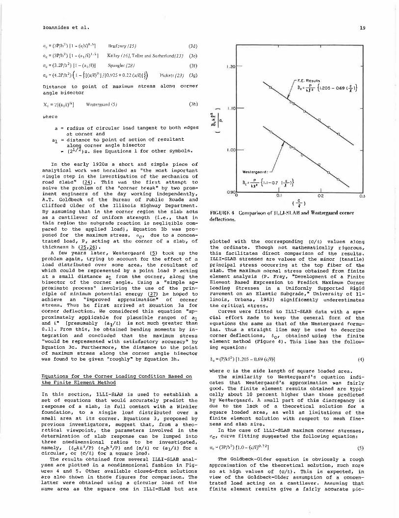
The results obtained from several ILLI-SLAB analyses are plotted in a nondimensional fashion in Figures 4 and 5. Other available closed-form solutions are also shown in these figures for comparison. The latter were obtained using a circular load of the same area as the square one in ILLI-SLAB but are
1. 20
1 .. 10
1 .. 00
Westergaard :
F.E. Results:
8,= k:' {1.205 - 0.69 <f >}
( ...£...) R
FIGURE 4 Comparison of ILLI-SLAB and Westergaard corner deflections.
19
plotted with the corresponding (c/Jl) values along the ordinate. Though not mathematically rigorous, this facilitates direct comparison of the results. ILLI-SLAB stresses are values of the minor (tensile) principal stress occurring at the top fiber of the slab. The maximum normal stress obtained from finite element analysis (P. Frey, "Development of a Finite Element Based Expression to Predict Maximum Corner Loading Stresses in a Uniformly Supported Rigid Pavement on an Elastic Subgrade," University of Illinois, Urbana, 1983) significantly underestimates the critical stress.
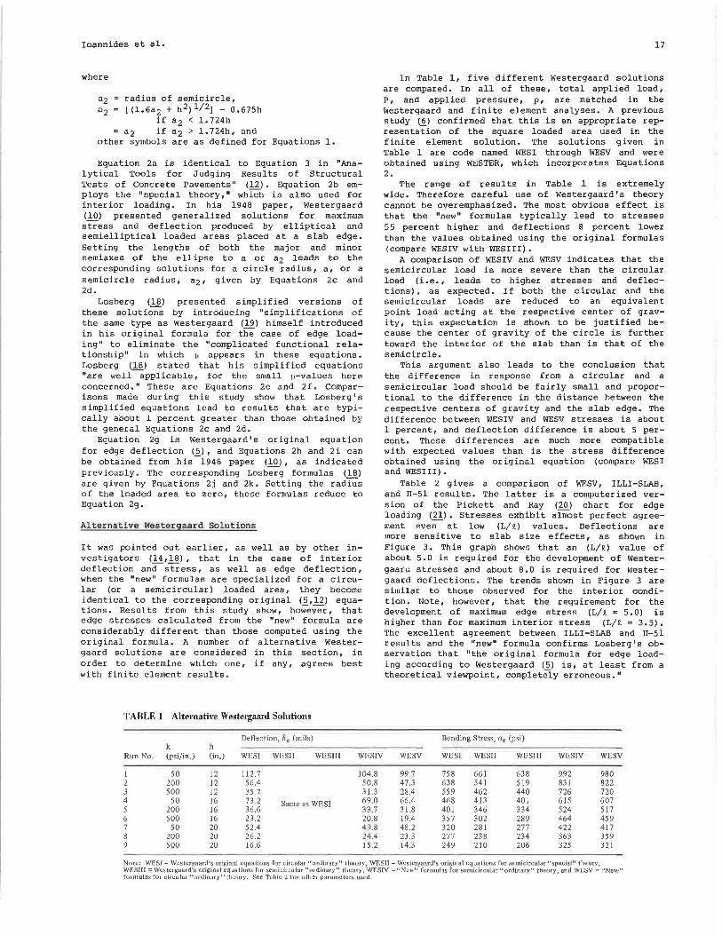
Curves were fitted to ILLI-SLAB data with a special effort made to keep the general form of the equations the same as that of the Westergaard formulas. Thus a straight line may be used to describe corner deflections, 6c, obtained using the finite element method (Figure 4). This line has the following equation:
60 = (P/kQ2) [1.205 - 0.69 (c/Q)] (4)
where c is the side length of square loaded area. The similarity to westergaard's equation indi
cates that Westergaard's approximation was fairly good. The finite element results obtained are typically about 10 percent higher than those predicted by Westergaard. A small par,t of this discrepancy is due to the lack of a theoretical solution for a square loaded area, as well as limitations of the finite element solution with respect to mesh fineness and slab size.
In the case of ILLI-SLAB maximum corner stresses, ac, curve fitting suggested the following equation:
(5)
The Goldbeck-Older equation is obviously a rough approximation of the theoretical solution, much more so at high values of (c/Jl). This is expected, in view of the Goldbeck-Older assumption of a concentrated load acting on a cantilever. Assuming that finite element results give a fairly accurate pie-

20
200
GoldbeckOlder
Pickett
Transportation Research Record 1043
~-:----~(I...... F..E . re1u1 1, ~ ------...,ucrr:or----n..11... ___ -0------..--(mor. . normal strtss) C 0 -----0......
1.ooo.._ ___________ o~.~0~5-----------o~.~,o,...-----------o.,,.... 1s.------------~o.·2~0----------~o .... 2s
( ....:... ) R
FIGURE 5 Nondimensional maximum bending stress for corner loading.
tllre of the theoretical sollltion, the Westergaard eqllation represents a considerable improvement over the Goldbeck-Older one. The finite element method gives reslllts that fall between those predicted by Westergaard (5) and those predicted by Bradbury (15). Note that the empirical modifications to the wE;;tergaard formllla proposed in the last 60 years-with the exception of BradbtJry's--have tended to increase the discrepancy between calclllated and theoretical stresses. These modified expressions are mllch closer to the Goldbeck-Older eqtJation than to the theoretical sollltion. Scott (~) points ollt that "experimental indications are that the corner stresses experienced in practice are higher than the Westergaard eqtJation indicates." Note, however, that, in the model tests mentioned previotJsly, meaSllred maxi mum corner stresses "were only 65 to 75 percent as great as those determined from the Westergaard equation" (2 2). The very significant limitations of the Winkler-sllbgrade idealization for corner loading are reflected in Figure 5. As a result, discrepancies between measured responses and theory may be expected. In the absence of more conclllsive field data, it is prlldent to design for a higher corner stress than indicated by Westergaard's formllla (Equation 3c).
Location of Maximum Stress
The results from a selected number of ILLI-SLAB runs are given in Table 3, where X1 as obtained from
TABLE 3 Location of Maximum Corner Stress
Equation 3h is compared with the location of the minor (tensile) principal stress given by ILLI-SLAB. This shows that ILLI-SLAB llsually gives a somewhat greater distance than Westergaard. On the other hand, model tests suggest values about 85 percent of Westergaard's (~).Curve fitting throllgh the values of x1 obtained by extrapolation from ILLI-SLAB, resulted in the following equation:
(6)
This best-fit eqtJation indicates that the inflllence of the radills of relative stiffness, JC, is much greater than that of the size of the loaded area. Westergaard' s equation suggests that these two parameters contribllte equally to the determination of X1•
Slab Size Requ irements f or Corner Load ing Westergaard Responses
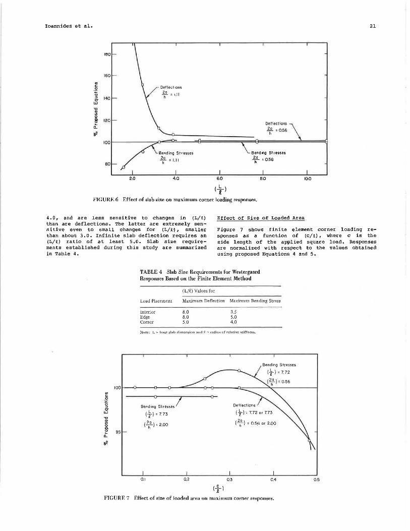
The pertinent results from this study are shown in Figure 6, in which ILLI-SLAB deflections and stresses are shown as percentages of the values given by the best-fit eqtJations. The validity of any concluR ions drawn from such a r:omparison is not r:onsidP.rP.d to be greatly affected by the numerical acctJracy of the proposed formulas. The patterns observed in Figllre 6 are the same as those observed for the other loading conditions. Once again, stresses converge faster, requiring a minimum (L/1 ) value of about
Location of Uc, X1 (in.)
lLLl-SLAB Q c Equivalent a
Run No. (in.) (in.) (in.) Equation 3h At Node By Extrapolation Proposed Equation
COOl 3 J.07 2.5 1.41 15.74 18.03 18.50 18.33 C002 31.07 5.0 2.82 22.26 25.50 22.93 22.88 C003 31.07 7.5 4.23 27.27 30.41 26.00 26.05 C004 36.95 5.0 2.82 24.28 25.50 25.45 25.34 coos 26.13 5.0 2.82 20.42 20.62 20.67 20.66 C006 22.92 5.0 2.82 19.12 18.03 19.11 19.12 COO? 38.56' 5.0 2.82 24.80 25.50 26.10 25.99 COil 31.07 5.0 2.82 22.26 25.50 22.93 22.88 CT3 31.07 10.0 6.56 33.96 28.28 28.42 28.56
Note: Equivalent a = (c/rry2), Equation 3h: X l = 21(a 1 12)
112 J. a 1 = (21/a) a, and proposed equation: X 1 = 1.80 c 0·
32 12° ·59
Ioannides et al.
IBO
160
en c .2 0 :::J 140 er w ,, ., en 0 ... 120 0
Q: tfl
100
80
2.0
Deflections
2ho =I.I I
4.0 6.0
( i l
Deflections
£.g_ = 056 h •
Bending Stresses
2ho = 0.56
B.O 10.0
FIGURE 6 Effect of slab size on maximum corner loading responses.
Effect of Size of Loaded Area
21
4.0, and are less sensitive to changes in {L/lt) than are deflections. The latter are extremely sensitive even to small changes for {L/lt-), smaller than about 3.0. Infinite slab deflection requires an (L/lt) ratio of at least 5 .o. Slab size requirements established during this study are summarized in Table 4.
Figure 7 shows finite element corner loading responses as a function of {c/lt), where c is the side length of the applied square load. Responses are normalized with respect to the values obtained using proposed Equations 4 and 5.
100 en c .2 0 :::J er w ,, ., en 0 ... ~ 95
a_
tfl
TABLE 4 Slab Size Requirements for Westergaard Responses Based on the Finite Element Method
Load Placement
Interior Edge Corner
(L/Q) Values for
Maximum Deflection Maximum Bending Stress
8.0 3.5 8.0 5.0 5.0 4.0
Note: L == least slab dimension and~== radius of relative stiffness.
0
Bending Stresses I (t)=773
( 2ho) = 2.00
0.1 0.2
(....£...) .e
Bending Stresses
( i ) = 7. 72
Deflections
(t) = 7.72 or 7.73
( 2h0
) = 0.5.6 or 2.00
0.3 0.4
FIGURE 7 Effect of size of loaded area on maximum corner responses.
0.5

22
Deflections are not very sensitive to changes in (c/Jt), but stresses diverge from the "theoretical" values as (c/Jt) exceeds about 0. 2. The trend exhibited by corner stresses is the reverse of that for interior loading. The effect of (c/Jt) on corner stresses is less pronounced than on interior stresses. Comments made earlier with respect to this effect are also generally applicable to corner loading.
CONCLUSION
Since their first appearance, beginning in the early 1920s, Westergaard equations have often been misquoted or rnisftpplied in subsequent publications. To remedy this situation, a reexamination of these solutions using the finite element method has been presented. This exercise yielded a number of interesting results:
1. Several equations ascribed to Westergaard in the literature are erroneous, usually as a result of a series of typographical errors or misapplications, or both. The correct form of these equations and their lirni tat ions have now been conclusively established (Equations 1-3).
2. Westergaard' s original equation for edge stress (2_) is incorrect. The long-ignored equation given in his 1948 paper (!Q) should be used instead.
3. Improved expressions for maximum corner loading responses have been developed (Equations 4-6).
4. Slab size requirements for the development of Westergaard responses have also been established (Table 4).
ACKNOWLEDGMENTS
The investigations for this paper were conducted under a research project (grant AFOSR-82-0143) sponsored by the Air Force Office of Scientific Research (AFOSR), Air Force Systems Command, Bolling Air Force Base, District of Colunl!Jia. Lt. Col. L.D. Hokanson was the Program Manager.
REFERENCES
1. A.M. Ioannides. Analysis of Slabs-on-Grade for a Variety of Loading and Support Conditions. Ph.D. dissertation. University of Illinois, Urbana, 1984.
2. A.M. Tabatabaie, E.J. Barenberg, and R.E. Smith. Longit~dinol Joint Systems in SlipForrned Rigid Pavements, Vol. II: Analysis of Load Transfer Systems for Concrete Pavements. Report FAA-RD-79-4, II. U.S. Department of Transportation, Nov. 1979.
3. O.C. Zienkiewicz. The Finite Element Method. 3rd ed. McGraw-Hill Book Company, New York, 1977.
4, D.J. Dawe. A Finite Element Approach to Plate Vibration Problems. Journal of Mechanical Engineering Science, Vol. 7, No. 1, 1965.
5. H.M. Westergaard. Stresses in Concrete Pavements Computed by Theoretical Analysis. Public Roads, Vol. 7, No. 2, April 1926. Also Proc., 5th Annual Meeting. HRB, National Research Council, Washington, D.C,, 1926, as Computation of Stresses in Concrete Roads.
6. M.R. Thompson, E.J. Barenberg, A.M. Ioannides, and J .A. Fischer. Development of a Stress Dependent Finite Element Slab Model. Report TR-83-1061. U.S. Air Force Office of Scientific Research, Air Force Systems Command, Bolling Air Force Base, Washington, D.C., May 1983.
7. H.M. Westergaard. Stresses in Concrete Runways of Airports. Proc., 19th Annual Meeting, HRB,
Transportation Research Record 1043
National Research Council, Washington, D.C., 1939. Also in Stresses in Concrete Runways of Airports. Portland Cement Association, Chicago, Ill., Dec. 1941.
8. R.F. Scott. Foundation Analysis. Prentice-Hall, Inc., Englewood Cliffs, N.J., 1981.
9. H.M. Westergaard. Stress Concentrations in Plates Loaded over Small Areas. ASCE Transactions, Vol. No. 108, 1943.
10. H,M, Westergaard. New Formulas for Stresses in Concrete Pavements of Airfields. ASCE Transactions, Vol. 113, 1948.
11. S. Tirnoshenko and S. Woinowsky-Kr ieger. Theory of Plates and Shells. 2nd ed., McGraw-Hill Book Company, New York, 1959.
12. H.M. Westergaard. Analytical Tools for Judging Results of Structural Tests of Concrete Pavements. Public Roads, Vol. 14, No. 10, Dec. 1933,
13. L.W. Teller and E.C. Sutherland. The Structural Design of Concrete Pavements, Part 5: An Experimental Study of the Westergaard Analysis of Stress Condition in Concrete Pavement Slabs of Uniform Thickness. Pubic Roads, Vol. 23, No. 8, April-June 1943.
14. S.G, Bergstrom, E. Frornen, and S. Linderholm. Investigation of Wheel Load Stresses in Concrete Pavements. Proceedings 13. Swedish Cement and Concrete Research Institute, Royal Institute of Technology, Stockholm, 1949,
15. R.D. Bradbury. Reinforced Concrete Pavements. Wire Reinforcement Institute, Washington, D.C., 1938.
16. E.F. Kelley. Application of the Results of Research to the Structural Design of Concrete Pavement, Public Roads, Vol. 20, No. 5, July 1935; Vol. 20, No. 6, Aug. 1939.
17. G. Pickett, M.E. Raville, W.C. Janes, and F.J. McCormick. Deflections, Moments and Reactive Pressures for Concrete Pavements. Bulletin 65. Engineering Experiment Station, Kansas State College, Pittsburg, Oct., 1951.
18. A. Losberg. Structurally Reinforced Concrete Pavements. Doktorsavhandlingar Vid Chalmers Tekniska Hogskola, Gotesborg, Sweden, 1960.
19. H.M. Westergaard. Orn Beregning af Plader paa elastik Underlag med saerlight Henblik paa Sporgsrnaalet om Spaendinger i Betonveje (On the Design of Slabs on Elastic Foundation with Special Reference to Stresses in Concrete Pavements). Ingenioren (Copenhagen), Vol. 32, 1923.
20. G. Pickett and G.K. Ray. Influence Charts for Concrete Pavements. ASCE Transactions, Vol. 116, 1951.
21. w.c. Kreger. Computerized Aircraft Ground Flotation Analysis--Edge Loaded Rigid Pavement. Research Report ERR-FW-572. General Dynamics Corp., Fort Worth, Tex., Jan. 1967.
22. P.F. Carlton and R.M. Behrmann. A Model Study of Rigid Pavement Behavior Under Corner and Edge Loadings. Proc., 35th Annual Meeting, HRB, National Research Council, Washington, D.C., l'lS6.
23. G. Pickett. Concrete Pavement Design, Appendix III: A Study of Stresses in the Corner Region of Concrete Pavement Slabs Under Large Corner Loads. Portland Cement Association, Skokie, Ill., 1946, reprint 1951.
24. H.M. Westergaard. Theory of Stresses in Road Slabs. Proc., 4th Annual Meeting, HRB, National Research Council, Washington, D.C., 1925.
25. A.T. Goldbeck. Thickness of concrete Slabs. Public Roads, Vol. 1, No. 12, April 1919.
2 6. C. Older. Highway Research in Illinois. ASCE Transactions, Vol. 87, 1924.
27. H.M. Westergaard. What is Known of Stresses. Engineering News Record, Jan. 1937.

Transportation Research Record 1043
28. M.G. Spangler. Stresses in the Corner Region of Concrete Pavements. Bulletin 157. Engineering Experiment Station, Iowa State College, Ames, 1942.
The contents of this paper reflect the views of the authors who are responsible for the facts and the
Establishing Load Transfer . Ill
Jointed Concrete Pavements
WOUTER GULDEN and DANNY BROWN
23
accuracy of the data presented herein. The contents do not necessarily reflect the official views ·or policies of the U.S. Air Force. This paper does not constitute a standard, specification, or regulation.
Publication of this paper sponsored by Committee on Rigid Pavements.
Existing
ABSTRACT
In this paper are described the results of a research project that had the objective of developing construction procedures for restoring load transfer in existing jointed concrete pavements and of evaluating the effectiveness of the restoration methods. A total of 28 test sections with various load transfer devices were placed. The devices include split pipe, figure eight, vee, double vee, and dowel bars. Patching materials used on the project included three types of fast-setting grouts, three brands of polymer concrete, and plain portland cement concrete. The number and spacing of the devices and dowel bars were also variables in the project. Dowel bars and double vee devices were used on the major portion of the project. Performance evaluations were based on deflection tests conducted with a 20,000-lb axle load. Horizontal joint movement measurements and visual observations were also made. The short-term performance data indicate good results with the dowel bar installations regardless of patching materials. The sections with split pipe, figure eight, and vee devices failed in bond during the first winter cycle. The results with the double vee sections indicate the importance of the patching material to the success or failure of the load transfer system: some sections are performing well and other sections are performing poorly with double vee devices. Horizontal joint movement measurements indicate that neither the dowel bars nor the double vee devices are restricting joint movement .
Many miles of Interstate pavement have been constructed using plain jointed concrete pavements of various thicknesses and joint spacings. The presence of a joint is a discontinuity that causes higher stresses and deflections in the pavement especially in the outside corner area. Many designs of jointed concrete pavement relied on aggregate interlock to provide for the transfer of the load across the joint, thereby reducing stress concentration and deflections under load, Laboratory studies conducted by the Portland Cement Association (PCA) found that the effectiveness of load transfer from aggregate interlock depended on load magnitude, number of repetitions, slab thickness, joint opening, subgrade value, and aggregate angularity (1). It was also found that the effectiveness decreased with cumulative load applications.
The variability of the amount of load transfer available from aggregate interlock created by changes in joint openings points out the need to provide for a more positive means of load transfer. In Georgia, and in many other states, dowel bars are placed in newly constructed pavements. Many older concrete pavements do not have the dowel bars and this absence of a posit i ve means of load transfer is a factor that contr i butes to the deterioration of these pavement sections. Faulting measurements made in Georgia in 1972 on projects that contained both doweled and nondoweled joints indicated that the presence of dowels reduced the rate of faulting (2) ,
The distress found in plain jointed concrete pavements in Georgia generally has been caused by the presence of an erodible base or subgrade, infiltration of surface water into the pavement system,