Embed Size (px)
Citation preview

8/19/2019 Welding Innovation Vol. XVII, No. 1, 2000
http://slidepdf.com/reader/full/welding-innovation-vol-xvii-no-1-2000 1/28

8/19/2019 Welding Innovation Vol. XVII, No. 1, 2000
http://slidepdf.com/reader/full/welding-innovation-vol-xvii-no-1-2000 2/28
Rarely does research lead directly to implementationwithout a significant delay in time. In contrast, I wouldlike to focus on a highly successful government-industry
initiative that has resulted in the rapid transfer of animportant new technology into actual applications. Theresearch involved the development of high-performancesteel, a material that already has been incorporated into63 bridges that are either in service, fabrication, orplanning.
What is the definition of high-performance steel? It issteel that combines high toughness and excellentatmospheric corrosion resistance with good weldability.The first material that was developed was HPS70W, a70 ksi yield strength steel. Current and future effortswill be devoted to developing HPS50W and 100W.
The Federal Highway Administration first learned aboutthe potential for HPS from a Department of Defense ini-tiative to develop “dual-use” commercial steels for mili-tary applications. This prompted an interagencyagreement between FHWA and the Carderock Divisionof the Naval Surface Warfare Center (CDNSWC) todevelop a grade of steel for use in bridges and ships.The CDNSWC then instituted a cooperative researchproject with the American Iron and Steel Institute (AISI).AISI subsequently brought in industry support from theAmerican Institute of Steel Construction (AISC), steelproducers, welding suppliers, bridge designers and vari-ous consultants to scope out a comprehensive plan tocapitalize on high-performance steel technology previ-ously developed for military applications.
Ultimately, one of the biggest technical challenges wasthe weldability of the new steel. While the heat-affectedzone (HAZ) was robust and immune from hydrogen-related cracking, new weld metals that were equallyrobust had to be developed. Two suppliers cooperatedto develop new filler metal combinations, and establishfabrication guidelines. This effort took place under theaegis of a Welding Advisory Group (WAG) which
included members of the AWS D1 Structural WeldingCommittee.
The development of the HPS70W steel itself was over-seen by a Steel Advisory Group (SAG). New designsto optimize the use of this steel were required, and a
JOINING TOGETHER:Public/Private Partnership Forges a New Technology
Design Advisory Group (DAG) was also formed. Inorder to make certain that issues regarding atmospher-ic weathering resistance of this HPS were properlyaddressed, a Corrosion Advisory Group (CAG) was
also formed. Each group assembled industry expertsto make certain that the research generated met thecriteria necessary for commercial success.
This effort was begun a short eight years ago, but atthe time of this writing, fourteen HPS bridges havealready been constructed. A further 49 HPS bridgesare currently in the design and fabrication stages.
Key to the success of this project has been the highdegree of public/private cooperation, which really madeit possible to “cover all the bases” from a technicalpoint of view. The early involvement of governmentagencies such as Calderock and FHWA, working inten-sively with industry associations such as AISI andAISC, provided a framework for industry support fromsteel producers, welding consumable manufacturers,and steel fabricators. Academic colleagues helped toround out a diverse group of experts who were able tosimultaneously address key issues of steel production,welding, design, and fabrication.
This particular public/private partnership has been a rous-ing success. I am pleased to have been involved in theeffort, and eagerly anticipate both the development of new
grades of high performance steel, and the discovery ofexciting new commercial applications for this technology.
William Wright, PEResearch Structural Engineer Federal Highway Administration Office of Infrastructure R&D.
Australia and New ZealandRaymond K. Ryan Phone: 61-2-4862-3839 Fax: 61-2-4862-3840
CroatiaProf.Dr. Slobodan Kralj Phone: 385-1-61-68-222 Fax: 385-1-61-56-940
RussiaDr.Vladimir P. Yatsenko Phone: 077-095-737-62-83 Fax: 077-093-737-62-87
INTERNATIONAL SECRETARIES
P h o t o c o u r t e s y o f T N
D O T

8/19/2019 Welding Innovation Vol. XVII, No. 1, 2000
http://slidepdf.com/reader/full/welding-innovation-vol-xvii-no-1-2000 3/28
1Welding Innovation Vol. XVII, No. 1, 2000
Cover: "Pneumatic Dreamer," a sculpture inbronze, exemplifies the art of welding, from
the inside, out. See story on page 23.
2 Alaskan Drill Rig is World's Largest
Rubber Tire VehicleA unique feature is the complete cantilever of the derrick and drill floor 18 ftabove the well, leaving clear working space around the well head.
15 The Xtracycle Sport Utility BicycleOne overall concept and two designs capitalize on the potential of thebicycle as a utility vehicle for both developing and industrialized countries.
23 "Pneumatic Dreamer" Sculpted of Bronze—and AirA human figure welded of strips of bronze slumbers atop the entranceto the W San Francisco Hotel.
The serviceability of a prod- uct or structure utilizing the type of information present- ed herein is, and must be,the sole responsibility of the builder/user. Many vari- ables beyond the control of The James F. Lincoln Arc Welding Foundation or The Lincoln Electric Company affect the results obtained in applying this type of infor- mation. These variables include, but are not limited to, welding procedure, plate chemistry and temperature,weldment design, fabrica- tion methods, and service requirements.
Volume XVIINumber 1, 2000
Editor
Duane K. Miller,Sc.D., P.E.
Assistant Editor
R. Scott Funderburk
The James F. LincolnArc Welding Foundation
Omer W. Blodgett, Sc.D., P.E.Design Consultant
Features
Award Programs
Departments
6 Lessons Learned in the Field:
Don't Assume Ductility is InherentIn a new column, Omer Blodgett shares some of the timeless lessons
he has learned about welded design, and asks Welding Innovation readersto do the same.
9 Design File: Carefully Evaluate “Code Requirements”
14 Opportunities: Year 2001 Production Welding
18 Key Concepts: Selecting Filler Metals: Low Hydrogen
21 Opportunities: Year 2001 Design Programs
22 PSST!
Visit Welding Innovation online at http://www.lincolnelectric.com/services/educate/innovate.asp
11 1999 Awards for Achievement in Arc Welded Design,
Engineering and Fabrication
THE JAMES F. LINCOLN ARC WELDING FOUNDATION
Dr.Donald N. Zwiep, Chairman
Worcester, MassachusettsJohn Twyble, Trustee
Mosman, NSW, AustraliaFrederick Stueber, Trustee
Cleveland, OhioRoy L.MorrowPresident
Duane K. Miller, Sc.D., P.E.Executive Director
TRUSTEES OFFICERS

8/19/2019 Welding Innovation Vol. XVII, No. 1, 2000
http://slidepdf.com/reader/full/welding-innovation-vol-xvii-no-1-2000 4/28
2 Welding Innovation Vol. XVII, No. 1, 2000
Alaskan Drill Rig Is World’s LargestRubber Tire Vehicle
By F. Charles KenleyPrincipal
Garth K. HowlettSenior Engineer
Peratrovich, Nottingham& Drage, Inc.
Anchorage, Alaska
IntroductionOil drilling technology on Alaska’s
North Slope has changed dramaticallyover the last twenty years. Drill rigshave developed from skid-mountedpieces of equipment to huge, integrat-ed and highly mobile machines thatcan move from well to well, from drillpad to drill pad, or even from field tofield, on frozen gravel or man-madeice roads.
Previously, North Slope land-based oildrilling rigs were movable two-sidedplatforms, which spanned over the wellhead to support the derrick above.These platforms had to be brokendown each time the rig was moved toanother well. They were trailered andtowed by truck or crawler.
Recently, Columbia Corporation ofPortland, Oregon, developed a largedrive-wheel system that has greatlyenhanced the mobility of these largepieces of machinery. The bogie sys-tems consist of twin 11-ft (3.3 m) diam-
eter rubber tires (see Figure 1), set upon an axle with a hydraulic drive motorand steering system. Each bogie iscapable of carrying 300 —400 tons (270360 m tons). With their huge tires andwheels, the bogie systems turn the drillrigs into enormous vehicles, capable ofmoving without disassembly to the nextwell head.
Directional drilling technology has alsoinfluenced the way drill rigs are con-structed. Many wells can now bedrilled from a single, small gravel pad,constructed to protect the tundra.These wells are placed as close as 10ft (3 m) on center, and fan out in alldirections as far as several miles.Wells even extend under the BeaufortSea to tap previously inaccessible
fields. While directional drilling hasmade pods of wells possible, the tightspacing of wells has led to strict spaceconstraints on the areas around thewells. Ideally, the derrick and drill floorwould be placed above the well on acantilevered gooseneck with nothingon the ground to interfere with theadjacent wells.
A drilling company, Pool Arctic Alaska,envisioned a new drill rig that wouldencompass all the new technology.The rig would be completely mobileand would be able to travel at 2.5 mph(4 km/hr) in any direction —forward,backward and side-to-side. Due to theextreme temperatures on Alaska’sNorth Slope, it would be self-con-tained, carrying its own pipe, fuel,
tanks, diesel-powered generators,hydraulic drive units, SCR electricaldrive units, stair towers, platforms andall equipment used for operation, pro-cessing and transport. It wouldinclude a crane-mounted piggybackthat would allow operators to build ortake the rig apart down to the majorframe components without mobilizinganother crane.
Figure 1. Axles and wheels arrive from Columbia Corp. Each bogie is capable of carrying 300 — 400 tons (270 — 360 m tons).
Return to TOC

8/19/2019 Welding Innovation Vol. XVII, No. 1, 2000
http://slidepdf.com/reader/full/welding-innovation-vol-xvii-no-1-2000 5/28
Welding Innovation Vol. XVII, No. 1, 2000 3
The result of this vision was PoolArctic Alaska Rig #6, a 3,000,000 lb(1,360,800 kg) welded steel behemothwhich Firestone Tire asserts to be thelargest rubber tire vehicle in the world.
DesignCriteria/Features• Derrick fully cantilevered over the
well (no jacking leg).• The capability to handle a 2,000 horse-
power (1,500 kW) draw-works anddrills as deep as 25,000 ft (7620 m).
• Derrick capable of handling 600,000lb (272,160 kg) of pipe set back inthe mast.
• Derrick capable of handling a hookload of 850,000 lb (385,560 kg)when the draw-works is pulling up
the drill stem.• Casing house capable of storing
drill pipe.• Rig rides on six sets of bogies with
a toal load capacity of 3,600,000 lb(1,632,960 kg).
• Twin welded steel box girders tosupport a cantilevered deck anddrill floor.
• Separate 2,000,000+ lb (907,200kg), 4-bogie mud module used for:drill mud processing, power genera-tion, fuel and water tanks, boilers,
and storage for other mechanicalequipment.
• Steel and welding procedures werespecifically selected for cold weatherconditions.
• Rapid erection and disassembly wasachieved by modular steel compo-nent design, and preassemby of allwelded steel.
• Rig to have a piggyback 100-ton(90.7 m ton) crane for self-disas-sembly.
• All components truckable: no pieceto weigh over 60,000 lb (27,216 kg)or to be longer than 60 ft (18.3 m).
Operationally, the rig would have to becapable of moving in several differentconfigurations, depending upon theroad or pad configuration and stability.
On a wide drill pad, the rig would movefrom well to well with the derrick upand positioned over the cantileveredbox beams. All six bogies would benecessary to carry the load. Whenlonger moves on the narrow roadswere required, the derrick would be slid
off the cantilever to a central positionon the rig and lowered to a horizontal
position. This would move the centerof gravity to a position in the middle ofthe rig, balancing the load between thefront and back wheels. The outside
sets of wheels on the rear would notbe usable on the narrow roadways, sofour sets of bogies could carry the rigin this configuration. The design had totake into account many load combina-tions for the drilling operation as wellas transportation.
Description of theStructureTwo 10 by 6 ft (3.0 by 1.8 m) box gird-ers located 18 ft (5.5 m) above theground form the structural backbone ofthe rig (see Figure 2). Box girderswere selected over box trusses
because they offered superior verticaland torsional stiffness, and are lighterweight, considering the geometry ofthe structure and anticipated drillingloads. Also, the interior of the boxcould serve as a heated corridor andutilidor from the front to the back of therig. In addition, fuel and water couldbe stored in built-in tanks inside thebox girders.
The box girders are supported bytransverse bolster beams to which the
wheel sets attach. The rear bolster(the fulcrum point of the cantilever) issupported by four sets of bogies. Twobogies support the front bolster. Thebox girders cantilever 40 ft (1.2 m)over the bolster at the rear of the rig tosupport the derrick and drill floor. The
The bogie systemsturn the drill rigs
into enormous vehicles
Figure 2. First test drive of the completed substructure. Box beams cantilever
from the rear end of the rig.
Return to TOC

8/19/2019 Welding Innovation Vol. XVII, No. 1, 2000
http://slidepdf.com/reader/full/welding-innovation-vol-xvii-no-1-2000 6/28
4 Welding Innovation Vol. XVII, No. 1, 2000
total load supported on the can-tilevered girders is in excess of2,000,000 lb (907,000 kg). The rigfloor, derrick and crane are clamped torails on top of the box girders and canbe slid to various positions atop thebox girders. Landing trusses and sill
beams extend to the ground and dis-
tribute loads to the gravel pad whenthe wheels are retracted for drilling
operations. Underslung between thefront and rear wheel sets and belowthe box girders is a 55 by 58 ft (16.8by 17.7 m) casing house. The casinghouse has a steel orthotropic deckcapable of supporting live loads of 500psf (2,440 MPa).
DesignThe modules were welded into assem-blies as large as possible without over-loading available transportation. BothRollagon tundra vehicles and C-130aircraft transports are limited toapproximately 60,000 lb (27,000 kg),which dictated the maximum sizeweldment. The modules were erectedand broken down many times; sub-assemblies were bolted or pinned toform the modules.
Connections were carefully reviewedwith consideration given to: minimizingconstruction difficulties; providing for
erection and disassembly a number oftimes in a remote Arctic environment;minimizing the potential for cold-weather fracture (either during fabrica-tion or in service); and the economicsof fabrication. It was foreseen that thestructure might have to be erectedunder Arctic winter conditions, byworkers wearing full Arctic gear includ-
ing heavily insulated mitts, which couldmake installation of bolts cumbersomeand slow.
Also affecting the design, detailing andchoice of materials was the fact thatmany of the loads on the structure are
dynamic. Moving loads generally arenot significant because of the rig’s lowvelocity, except in the event the 26 ft(8.0 m) wide rig went off the 30 ft (9.0m) wide roads of the North Slope.During operation, the drill module candevelop significant dynamic forces.Careful consideration was given toproviding load-path redundancy, par-ticularly for the dynamically loadedelements. The box girder sections ofthe substructure provide excellent stiff-ness and redundancy.
Due to the type of anticipated loadsand the Arctic environment, it wasdeemed acceptable to design usingthe AISC Specifications and the AWSStructural Welding Code-Steel (AWSD1.1) while including detailing andmaterial practices more typical of cold-weather bridges. Design parametersincluded load-path redundancy, use ofnotch tough materials (particularly atconnections) and nondestructive test-ing of critical connections and mem-bers. Due to the tight fabricationschedule, care was taken to providemultiple material specifications wherepossible.
FabricationMaterials were carefully chosen toexhibit good mechanical propertiesincluding notch toughness at low tem-peratures. Most of the steel used wasA572 Grade 50 with a supplemental
notch toughness specified at a mini-mum of of 15 ft-lb @ -40°F (20 J @-40°C) for plate and 15 ft-lb @ -20°F(20 J @ -30°C) for rolled shapes. Thefabricator elected to build many of thesections from plate because of the dif-ficulty in obtaining rolled sections thatwould meet the cold-temperature spec-ification. Tubular members, typically
used for structural bracing, were speci-fied as API 5LX-52.
To minimize erection difficulties, thebolts and studs were typically 1-1/2 in(38 mm) in diameter or larger. Thebolts chosen for low temperatures
were ASTM A320 L7 or L43 or A193-S2 B7. All the connection materialswere required to provide a minimumCVN impact value of 20 ft-lb @ -150°F(34 J @-100°C).
Shear pins 1-1/2 in (38 mm) or less indiameter were permitted to be A320L7 or L43. Pins greater than 2-1/2 in(63 mm) in diameter were used inareas of less structural redundancy.
Weld DesignWelding was specified to conform toAWS D1.1-96. To provide requirednotch toughness, fairly specific weld-ing filler materials were required. Forweld throats 1-in (25 mm) thick or lessthe use of E7018-1 or E8018 was per-mitted for SMAW, and E71T8-Ni 1% orNi 2% was permitted for FCAW.Welds with a greater than 1-in. throat,and/or Complete Joint Penetration(CJP) groove welds, required a rootpass using E6010, followed up withSMAW E8018 or FCAW E71T8-Ni 2%.Web to flange fillets were permitted tobe SAW F7A2-ENi1K. All filler metalswere required to provide a minimumas-welded CVN value of 20 ft-lb @20°F (40 J @ 10°C). These materials,
Figure 3. Fabrication of the 6 by 10 ft (1,800 mm by 3,000 mm) box beam
sections.
Twin welded steelbox girders supporta cantilevered deck
and drill floor
Return to TOC

8/19/2019 Welding Innovation Vol. XVII, No. 1, 2000
http://slidepdf.com/reader/full/welding-innovation-vol-xvii-no-1-2000 7/28
Welding Innovation Vol. XVII, No. 1, 2000 5
as well as notch-free joint details andlower stresses, help provide a fracture-resistant joint even in cold Arctic tem-peratures.
Splices or joints in materials greaterthan 1-in (25 mm) thick were required
to maintain preheat and interpass tem-peratures of 150°F (83°C) duringwelding. All Welding ProcedureSpecifications (WPSs) were requiredto be prequalified per AWS D1.1 orqualified by test.
Members were fabricated into sub-assemblies (Figure 3). Sub-assemblybolt-holes were sub-punched duringfabrication, and were temporarily sup-ported. Bolted and pinned connec-tions were match-marked andaccurately drilled.
The structure was fully erected prior toshipment to the field. The fabricatorchosen by Pool Arctic Alaska wasThompson Metal Fabricators ofPortland, Oregon.
InspectionAll weldments were required to bevisually inspected by a CWI inspector.Visual inspection was performed perAWS D1.1. All CJP welds were fullynon-destructively tested ultrasonicallyor radiographically. Flange splice con-nections of all primary beams andgirders were required to meet AWSrequirements for cyclic loaded mem-bers and connections, confirmed byultrasonic or radiographic testing.
ConclusionsIn the Alaskan Arctic, prefabricatedwelded structural steel continues toprovide designers with reliable andefficient solutions to difficult technicaland logistical problems. In this case,welded steel significantly reduced the
budget and schedule, while improvingthe constructibility of Rig 6 (Figures 4and 5). Prefabrication of the substruc-tural components in Portland was verycost-effective. The ability to truck thecomponents over the North Slope haulroad also provided a savings overbarging. The welded steel structureprovides the owners with savings incost as well as maintenance and oper-ational expenses, versus other typesof standard construction materials.
Modules were erectedand broken down
many times
Figure 4. The drill rig control room.
Figure 5. The completed drill rig module, with 100 ton (90.7 m ton) crane sittingpiggyback. The mast extends 80 ft (24.4 m) above the drilling floor.
Return to TOC

8/19/2019 Welding Innovation Vol. XVII, No. 1, 2000
http://slidepdf.com/reader/full/welding-innovation-vol-xvii-no-1-2000 8/28
6 Welding Innovation Vol. XVII, No. 1, 2000
IntroductionAt this point in my life, I am in thehappy position of being able to contin-
ue to do the work I love, while alsohaving a long career to look back on.Although I was the fortunate recipientof an excellent engineering education,from this vantage point, it seems thatmy most significant learning experi-ences actually took place not in theclassroom, but in the field. I wouldguess that the same is true for manyreaders of Welding Innovation .Therefore, the staff of the magazineand I are asking you, our readers, toshare these valuable lessons with yourcolleagues and associates. In futureissues, this column will provide aforum for that exchange.
Here’s the idea: sometimes we engi-neers act a little like horses with blind-ers on. We concentrate sosingle-mindedly on the problem athand, that we can’t really see what’sgoing on around us. For this column,I’m looking for stories that illustratehow critical it is for us as engineers to
take our blinders off, expand our limit-ed world view, and test our assump-tions. Often, we find that the “evident”solution turns out to be a deadend,and pursuing a path that at firstseemed counter-intuitive will actuallysolve the problem. Can you think of
any examples from your own experi-ence? Those are the “lessons” we’d
like to publish.
To launch this feature, and in futureissues, I’ll share some of my “ah-ha!”moments. But don’t leave me aloneon this page—we’re looking for theadded value that only you, our col-leagues, can provide. Your submis-sions may be accompanied byphotographs or drawings. Simplehand-sketches are fine—our artist willre-draw them and check with you tomake sure the rendition is accurate.
Here’s just one example of the type ofitem you might submit.
Ductility May NotBe InherentEngineers have been taught that theyield point property of a material is theprime factor relating to ductility. This,however, offers a limited view. Figure 1shows a stress-strain curve applied toa steel specimen which is loaded in
tension parallel to its length. In thistype of test, the specimen is free toneck-down once the yield strength isreached (b). As it plastically yields, itstrain-hardens to a higher strength (bto c). This stress continues to increaseto (d), but because of a reduction inthe cross-section, its apparent strengthdrops from (c) to (d).
If the load is removed, the specimenwill not return to its original dimen-
sions. Within the limit of elastic behav-ior occurring from (a) to (b), however,movement is small and would not benoticed unless measured. If the speci-men’s load is removed, it will return toits original dimensions with a spring-like movement. For example, if a steel
Don’t Assume Ductility is Inherent
Often, the“evident” solutionturns out to be
a deadend
Figure 1.
Lessons Learned in the Field
by Omer W. Blodgett, Sc.D., P.E.
Return to TOC

8/19/2019 Welding Innovation Vol. XVII, No. 1, 2000
http://slidepdf.com/reader/full/welding-innovation-vol-xvii-no-1-2000 9/28
Welding Innovation Vol. XVII, No. 1, 2000 7
plate has a yield strength of 40 ksi,elastic deflection would be:
In the laboratory, it is typical to think of
applying a force to a tensile specimenso that its resulting strain or movementmay be observed. But this is not whatreally happens with a tensile lab test-ing machine. When the machine is
activated, a motor gradually turns ascrew feed which slowly strains orstretches the specimen in the longitu-dinal direction. The resisting force ofthe specimen against this strainingmovement is indicated on a gauge.Yield strength is reached when theapplied stress exceeds the criticalpoint, and the specimen is free to
plastically neck-down. If the materialis restrained, as it may be in real-world applications, the stress-straincurve indicated in Figure 1 may contin-ue to the point of ultimate tensilestrength in an almost straight path,until it ultimately fails without exhibiting
much apparent ductility.
When an axial force (F) is applied to atest specimen, it will cause a normalstress (σ) on a plane 90 degrees tothe direction of the force. It also caus-es a shear stress (τ), which reachesits maximum on a plane 45 degrees tothis force, and is equal to one-half thevalue of normal or tensile stress. Ifthis shear exceeds a critical valueequal to one-half of the yield strength,a sliding action takes place, allowing
the specimen to become longer in thedirection of the force and more narrowacross its width. If the resulting shearvalue is low, based on design, and thecritical shear stress point cannot bereached, then an increased load willmean failure when the critical tensilepoint is exceeded.
Sliding action can also take place onthe 45 degree plane in the other direc-tion. If the action continues, a necked-down elongation results in atensile-tested specimen as Figure 2indicates. The slip plane lies at 45
degrees, forming a reduced section,initially having a square outline. If theunrestrained length (L) of this sectionis at least equal to or greater than thewidth (W), the specimen will be free toneck-down and show full ductility. Ifthe unrestrained length (L) is less than
the width (W), the shear component(τ) will decrease. A greater appliedforce will be necessary for the criticalshear value to be exceeded, reducingits ductility. This is one reason theAISC LRFD and ASD Specificationsrequire the weld access hole to extenda distance on each side of the weldequal to three times the web thicknessfor jumbo shapes. Doing so providesan unrestrained length of flange, giv-ing the specimen increased ductility.
In the field, specimens do not usuallyexist independently. Steel plates areoften restrained and not free to neck-down. The weld solidifies and shrinksas it cools, similar to a steel casting.When this shrinkage or strain isrestricted, a high residual tensilestress results, sometimes sufficient tocause some part of the joint to pullapart and crack.
Instead of focusing on stresses whichmight cause such a crack in the weld-ed joint, the engineer would be betteradvised to consider strains and howthey can be reduced to avoid cracking.Minimizing distortion due to weldingand residual stress factors will helpreduce these strains when arestrained member is welded.
Figure 2.
Engineershave been taught
that the yield pointproperty of a material
is the prime factorrelating to ductility...this offers alimited view
40,000 psi30x106 psi
= 0.0013 in./in.ε = =σ
Ε
Return to TOC

8/19/2019 Welding Innovation Vol. XVII, No. 1, 2000
http://slidepdf.com/reader/full/welding-innovation-vol-xvii-no-1-2000 10/28
8 Welding Innovation Vol. XVII, No. 1, 2000
It is possible to take a representativestress-strain curve for mild steel(Figure 3a), separate the plastic strainportion from it (Figure 3b), and convertthis into a shear stress-plastic strainfor any given shear stress (τ) once it
exceeeds the critical shear value. Theshear stresses (τ1-3) and (τ2-3) can nowbe converted into plastic strain pluselastic strain as the value of theapplied normal stress (σ3) isincreased. A stress-strain curve forany combination of triaxial stressesmay be constructed. Figure 4 containscurves for the conditions already dis-cussed. This makes it possible to“see” the ductile behavior of thesedetails. Notice the beneficial effects ofthe wide access hole as recommend-
ed by the AISC specifications.
The way in which a designer selectsstructural details under particular loadconditions greatly influences whetherthe condition provides a high enoughshear stress component so that thecritical shear value may be exceededfirst, producing sufficient plastic move-ment before the critical normal stressvalue is exceeded. This will result in aductile detail and minimize the
chances of cracking.
Figure 4.
Figure 3.
Return to TOC

8/19/2019 Welding Innovation Vol. XVII, No. 1, 2000
http://slidepdf.com/reader/full/welding-innovation-vol-xvii-no-1-2000 11/28
Welding Innovation Vol. XVII, No. 1, 2000 9
Carefully Evaluate“Code Requirements”Practical Ideas for the Design Professional by Duane K. Miller, Sc.D., P.E.
Design File
Codes, specifications, and contract documents providefabrication requirements that must be maintained whenapplied to welded construction. However, some provisionsare perceived as “requirements” when they are not applic-able, or when alternatives are permitted. Under these
conditions, it is prudent to carefully evaluate such “require-ments” and, when appropriate, consider alternatives thatmay provide fabrications of equal or better quality, and atreduced cost.
Consider, for example, the requirements as they relate toComplete Joint Penetration (CJP) groove welds made inaccordance with the American Welding Society StructuralWelding Code – Steel (AWS D1.1:2000). A review of theprequalified joint details in AWS D1.1, Figure 2.4 revealsthat all CJP groove welds (with one exception which will bediscussed below) utilize either single-sided joints with steelbacking, or double-sided joints that involve back gouging(see Figures 1 and 2). Either option is permitted, and whenproperly made, both should result in a weld throat that isequivalent to the thickness of the thinner base metal joint.
The single exception to this is the B-L1-S detail (see Figure3), which is limited to a maximum thickness of 3/8 in (10mm). This detail relies on the penetration of the sub-merged arc welding process to achieve a CJP groove weld.
It would be easy to conclude that AWS D1.1 requires either(a) steel backing for one-sided joints, or (b) double-sided joints that use back gouging. However, this conclusion
would be incorrect, and a careful evaluation of code“requirements” with respect to this criterion will reveal thatthe code permits alternatives.
The key principle that provides understanding in this partic-ular instance is the difference between prequalifiedWelding Procedure Specifications (WPSs) and those thatare qualified by test. In order for a WPS to be prequalified,it must comply with all the criteria of Chapter 3 in the AWSD1.1 Structural Welding Code. However, it is also possibleto qualify WPSs by test in conformance with AWS D1.1,Chapter 4 - Qualification. Such qualification testing could
Figure 1. Single-sided CJP weld with steel backing.
Figure 2. Back-gouged double-sided CJP weld.
Figure 3. Prequalified AWS D1.1 joint detail B-L1-S
(used with permission of the American Welding Society).
Return to TOC

8/19/2019 Welding Innovation Vol. XVII, No. 1, 2000
http://slidepdf.com/reader/full/welding-innovation-vol-xvii-no-1-2000 12/28
10 Welding Innovation Vol. XVII, No. 1, 2000
In the preceding case study, the cost savings achievedwere impressive. Equally important, overall quality isexpected to be enhanced since reliance is made upon a
system that includes careful control of the welding proce-dures for the root pass, rather than on back gouging opera-tions that are inherently subject to variations in operatorskill. As is frequently the case, this cost-saving effort alsoimproved quality.
thereby permit the use of other materials for backing,including ceramic, glass tape, copper and iron powder(see AWS D1.1, Section 5.10).
Qualification testing could similarly permit the use of dou-ble-sided joints without back gouging. This is specificallyaddressed in AWS D1.1, Table 4.5 – “PQR EssentialVariable Changes Requiring Requalification for SMAW,
SAW, GMAW, FCAW, and GTAW,” Item 35. This provisionstates that “the omission, but not inclusion, of backing orback gouging” would require qualification of the WPS.
Case StudyFor many years, a fabricator had made CJP groove weldsin T-joints for offshore applications, using double-sided joints with back gouging, consistent with the prequalifiedAWS D1.1 joint detail TC-U5-GF (see Figure 4). Ratherthan incorrectly assuming that back gouging of two sidedCJP groove welds was a “requirement,” this fabricator tookadvantage of the D1.1 Code alternative which permitted
WPS qualification without the use of back gouging.
The alternative approach replaced the back gouging opera-tion with a unique root pass procedure that ensured a CJPgroove weld. The overall joint was a tee, composed of two3 in (75 mm) steel members, and was prepared with adouble bevel groove preparation, using a 50 degree includ-ed angle, no root opening and no root face. Two pulsedGMAW arcs, operating from opposite sides of the web,simultaneously made the root passes. Longitudinal spac-ing for the opposed arcs was approximately 1/2 in (12mm). Figure 4 shows the root passes, with complete pene-tration. Figure 5 shows the completed joint that was filled
with pulsed GMAW as well.
Such techniques necessitated WPS qualification testing,but the potential cost savings greatly outweighed theexpense of the WPS qualification testing.
ConclusionsReevaluation of “requirements” such as backing or backgouging for AWS D1.1 CJP groove welds may permit theuse of cost-effective alternatives. Once a WPS is qualified,it then may be submitted to the Engineer for approval, con-sistent with AWS D1.1, Section 4.1.1.
In other situations, Code provisions can be waived andalternatives permitted when approved by the Engineer. Forexample, AWS D1.1, Section 6.8 permits the Engineer touse alternative criteria for specific applications. Approvingalternatives should not be casually approached, and theEngineer is encouraged to rely upon prior experiencedengineering judgment, in addition to analytical or experi-mental data. However, alternatives can be approved in thismanner, permitting viable alternatives.
Figure 4. Pulsed GMAW root passes on 3 in. (75 mm)
thick members.
Figure 5. CJP groove weld completed by pulsed GMAW without back gouging.
Return to TOC
8/19/2019 Welding Innovation Vol. XVII, No. 1, 2000
http://slidepdf.com/reader/full/welding-innovation-vol-xvii-no-1-2000 13/28
11Welding Innovation Vol. XVII, No. 1, 2000
JURY OF AWARDS
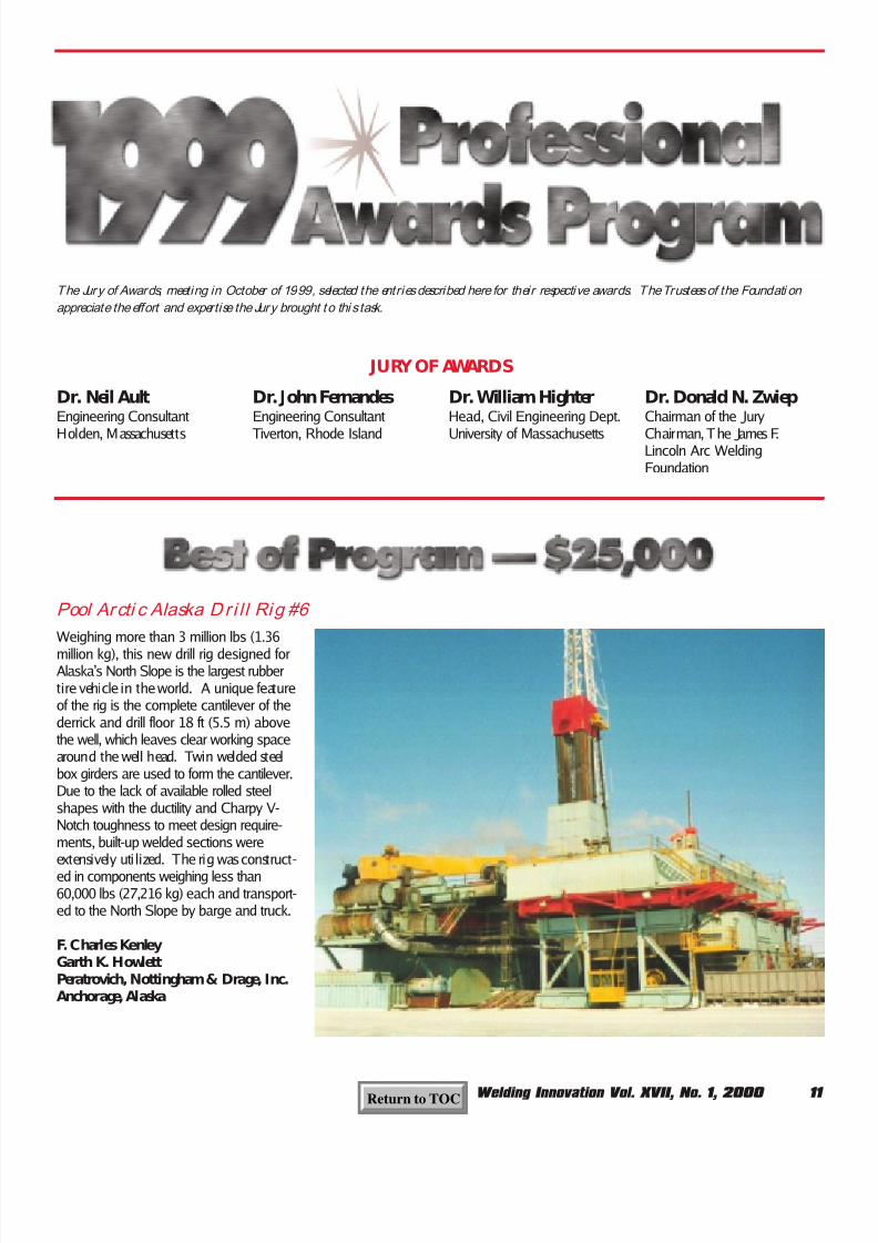
Weighing more than 3 million lbs (1.36
million kg), this new drill rig designed forAlaska’s North Slope is the largest rubbertire vehicle in the world. A unique featureof the rig is the complete cantilever of thederrick and drill floor 18 ft (5.5 m) abovethe well, which leaves clear working spacearound the well head. Twin welded steelbox girders are used to form the cantilever.Due to the lack of available rolled steelshapes with the ductility and Charpy V-Notch toughness to meet design require-ments, built-up welded sections wereextensively uti lized. The rig was construct-
ed in components weighing less than60,000 lbs (27,216 kg) each and transport-ed to the North Slope by barge and truck.
F. Charles KenleyGarth K. HowlettPeratrovich, Nottingham & Drage, Inc.Anchorage, Alaska
The Jury of Awards, meeting in October of 1999, selected the entries described here for their respective awards. The Trustees of the Foundati on
appreciate the effort and expertise the Jury brought to thi s task.
Dr. Neil AultEngineering Consultant
Holden, Massachusetts
Dr. John FernandesEngineering Consultant
Tiverton, Rhode Island
Dr. William HighterHead, Civil Engineering Dept.
University of Massachusetts
Dr. Donald N. ZwiepChairman of the Jury
Chairman, The James F.Lincoln Arc WeldingFoundation
Pool Arcti c Alaska Dr i l l Rig #6
Return to TOC

8/19/2019 Welding Innovation Vol. XVII, No. 1, 2000
http://slidepdf.com/reader/full/welding-innovation-vol-xvii-no-1-2000 14/28
12 Welding Innovation Vol. XVII, No. 1, 2000
One of the most critical members in a2,100 ft (640 m) cable stayed bridge is thatconnecting the steel plate girder web to thestay cable. Due to changing forces in thestay, this member is subject to fatigue. Theproblem was to design a connecting mem-ber that did not pierce the top flange of theplate girder. It was decided that the connec-tion should go around the top flange andconnect to the girder web. Attention todetail and the use of arc welding made pos-sible the design and erection of a veryfatigue-resistant connection which eliminat-ed the need to pierce the top flanges of thesteel plate girders.
William B. CarolandAmerican Consulting EngineersLexington, Kentucky
Arc welding technology permitted thedesign and construction of the spectacular
tri-chord roof trusses that crown Seattle’snew Safeco Field baseball stadium. Thethree independent roof panels cover 8.7acres (3.5 hectares), with the largest centerpanel 275 ft (84 m) above the playing field.The two lower panels that slide underneaththe center panel in the retracted positionhave downturned trusses with a bottomchord 165 ft (50 m) above the field. Forquality control and higher production rates,components were shop welded whereverpossible. Fabricators developed detailedwelding procedures that minimized distor-
tion of the plates and chord elements,resulting in excellent fit-up of the trusses inthe field, with a minimum number of fieldmodifications required.
Kurt A. NorquistSkilling Ward Magnusson Barkshire, Inc.Seattle, Washington
Safeco Field Roof Trusses
Fatigue- Resistant Connection for a Cable-Stayed Bridge
Return to TOC

8/19/2019 Welding Innovation Vol. XVII, No. 1, 2000
http://slidepdf.com/reader/full/welding-innovation-vol-xvii-no-1-2000 15/28
Welding Innovation Vol. XVII, No. 1, 2000 13
The design and construction of innovativesubmersible bridges on the North Slope of Alaska saved the owner $10 million over thecost of elevated bridges for the crossing of tworiver channels in a flood plain nearly two miles(3.2 km) wide. Extreme environmental condi-tions, design vehicle weights approaching 4million lbs (1.8 million kg), impact loadingfrom river ice 5 ft (152 cm) thick, and discon-
tinuous permafrost soil conditions all com-bined to provide unusual design andconstruction challenges. The design of a weld-ed steel structure allowed rapid construction,field welded joints, compact girder sections, astreamlined shape for reduced ice impact loadsand low maintenance in the future.
Kenton W. BraunAlan B. ChristophersonDempsey S. ThiemanPeratrovich, Nottingham & DrageAnchorage, Alaska
A 250-foot radius horseshoe shape weldedsteel orthotropic bridge was designed as an
interchange at the intersection of twoCalifornia freeways. Steel was chosen by thestate department of transportation to mini-mize travel delays or lane closures duringbridge erection. An orthotropic design withtrapezoidal ribs was selected by the consultingengineering firms. The unique 180-degreecurve forming the horseshoe shape of thebridge made a closed cell structure the mosteconomical shape to resist the torsional forces.
Carl Huang Alfred MangusTony Marquez James E. Roberts
CaltransSacramento, California
Michel BenoitBuckland & Taylor COWI GroupWalnut Creek, California
John WilliamsICF Kaiser EngineersOakland, California
Kuparuk River Submersible Bridges
North America’s First Curved Welded Steel Orthotropic Bridge
Return to TOC

8/19/2019 Welding Innovation Vol. XVII, No. 1, 2000
http://slidepdf.com/reader/full/welding-innovation-vol-xvii-no-1-2000 16/28
14 Welding Innovation Vol. XVII, No. 1, 2000
The Xtracycle is a MIG-welded (GMAW)tubular-steel frame which permits the eco-
nomical conversion of an ordinary bicycleinto a load-hauling sport/uti li ty vehicle. Afixture that attaches to (and detaches from)virtually any existing bicycle, the Xtracyclecreates a vehicle that can haul groceries,packages, lumber, computers, passengers,firewood, and many other types of cargo onrugged terrain with loads of up to 200 lbs(90 kg). It is particularly applicable to theneeds of people living in developing coun-tries (where bicycles are a common mode of transportation) and has been designed to beeasily replicated in local welding and
machine shops using readily available tools,materials and skills.
Ross EvansKipchoge SpencerXtracycle InternationalNevada City, California
The Xtracycle Sport Utility Bicycle
Opportunities
2001
Production WeldingBasic
Advanced
Lincoln Electric’s professional education programs set the standard for the indus-try. Each section of Production Welding is a 3-day program conducted by LincolnElectric’s staff of expert welding engineers. The Basic course includes: arc weldingprocesses and procedures; arc blow and proper grounding; wire feeding tech-niques; distortion; destructive testing; safety; and more. The Advanced curriculumincludes: pulse GMAW; tandem GMAW; twin and tandem SAW; aluminum weld-
ing; stainless steel welding; surface tension transfer (STT); robotic welding; wave-form development; nondestructive testing; and more. 2.0 CEUs.Fee: $395.
2001 dates will be posted on our website:www.lincolnelectric.com/services/educate/educate.asp
…as soon as they are available.
Return to TOC

8/19/2019 Welding Innovation Vol. XVII, No. 1, 2000
http://slidepdf.com/reader/full/welding-innovation-vol-xvii-no-1-2000 17/28
Welding Innovation Vol. XVII, No. 1, 2000 15
By Ross Evans andKipchoge Spencer
Co-FoundersXtracycle InternationalNevada City, CA
IntroductionWhile the standard bicycle is well-known as a low-cost, non-pollutingmode of transportation available to
most of the world’s population, itsvalue as a utility vehicle is yet to befully realized. The Xtracycle (Figure 1)is a fixture that can be attached to, ordetached from, virtually any existingbicycle, elongating its frame andreadying it for a burden. The resultingextended-wheelbase vehicle retainsthe simple efficiency of the bicyclewhile greatly increasing its effective-ness. A modular plug-in rack systemmakes it possible to configure theXtracycle for hauling loads that werepreviously considered too long, heavy,bulky, perishable, fragile, or importantto be transported by bicycle. AnXtracycle-equipped bike can haul gro-ceries, packages, lumber, computers,passengers, water, firewood, cellos,bread, and nearly any other cargo onrugged terrain. The device will handleloads of up to 200 lbs (400 lbs with anoptional heavy-duty rear wheel), whilemaintaining the handling characteris-tics of a mountain bike.
The InspirationMany of the world’s poor have little orno means of transporting cargo otherthan on foot, and thus spend severalhours per day carrying such loads asgoods, firewood, and water on theirbacks—and heads. Yet many of thesesame people own or have access to a
bicycle, a vehicle that is extremely effi-cient for transportation but unsuited forcarrying substantial loads. One inspi-ration for the development of theXtracycle, then, was to augment thebicycle’s cargo-carrying capacity,thereby freeing hundreds of millions of
people from extreme physicaldrudgery. The challenge was to devel-op a device that would accomplish thistask, while also being affordable to thetarget market.
In wealthy countries (especially inWestern Europe), businesses, commu-
nity services, and individuals areincreasingly turning to the bicycle as ameans of travelling more quicklythrough areas gridlocked by automo-bile traffic. In this setting, increasingthe bicycle’s load carrying capacity willenable even those who have a choiceof transportation methods to use thebicycle to meet more of their needs.For example, in the gridlocked traffictypical of some urban environments,the bicycle can provide an idealmeans of reaching heart attack or
accident victims and stabilizing themin preparation for the arrival of anambulance. The Xtracycle permitsparamedics to carry life-saving equip-ment (e.g., defibrillator, oxygen, and abackboard) that will save preciousminutes during the anxious wait for anambulance making its way throughheavy traffic.
The XtracycleSport Utility Bicycle
The conversion takesfrom five to thirtyminutes…and is
completely reversible…
Figure 1. The Xtracycle can turn virtually any existing bicycle into a load-carry-
ing vehicle.
Return to TOC

8/19/2019 Welding Innovation Vol. XVII, No. 1, 2000
http://slidepdf.com/reader/full/welding-innovation-vol-xvii-no-1-2000 18/28
16 Welding Innovation Vol. XVII, No. 1, 2000
How the Xtracycle Works
The Xtracycle is installed on a bicycleby first removing the bike’s rear wheel.Then the Xtracycle is attached to thebike’s frame at three points usingquick-release bolts.
Two attachment points are thedropouts where the rear wheel hadbeen; the other is near the bottombracket, home of the pedal crank spin-dle. Then the rear wheel slips into theXtracycle’s own dropouts. A section of
chain is added, brakes and derailleurare moved, and the Xtracycle is readyto haul. The conversion takes fromfive to thirty minutes, depending uponthe particular bike. Installation is com-pletely reversible, but it is anticipated
that most users will choose to leavethe Xtracycle installed, since it doesn’tdetract from the bike’s rideability.
Two ModelsXtracycle International has developedtwo base frames, one intended primari-ly for developed countries called the
FreeRadical™ (Figure 2), and anotherdesigned for developing countries, theextrabike™ (Figure 3). TheFreeRadical is more modular; the engi-neering behind its lighter-weight con-struction makes it more complex tomanufacture and not as well suited to
small-scale production as the extra-bike. The FreeRadical is primarily TIG-welded using round 4130 chromolysteel tubing with a wall thickness of0.039 in (1 mm) in diameters of 0.75(20 mm) and 1.0 in (25 mm), whichgives it a sleeker look than the squaretubing of the extrabike. However, whatthe extrabike lacks in modularity, itgains in versatility: with its permanentfold-down racks and solid top-frameconstruction, it carries a wide range ofloads without modification.
The Contributionof WeldingFor the inventor, Ross Evans, learningto weld was the genesis of theXtracycle concept. Even more impor-tantly, the ability to weld prototypes foruser testing led to rapid advancementof the design, and to significant inno-vations. He has taught the skill of
..the ability to weld
prototypes for usertesting led to rapidadvancement of the
design…
Figure 2. The modular, TIG-welded FreeRadical™ model is intended for use
primarily in developed countries.
Figure 3. The sturdy extrabike™ model is well-suited to the small scale produc-
tion situations typical of developing countries.
Return to TOC

8/19/2019 Welding Innovation Vol. XVII, No. 1, 2000
http://slidepdf.com/reader/full/welding-innovation-vol-xvii-no-1-2000 19/28
Welding Innovation Vol. XVII, No. 1, 2000 17
welding to farmers in Nicaragua andfishermen in Senegal, recognizing thetrue empowerment of people as theysee the implications of their ability toweld. As Rafael Solis, a trainee inManagua, Nicaragua, exclaimed, “NowI can make anything!” (Figure 4)
The advent of small, inexpensive,portable MIG welders has aided thedesign, growth and spread of theXtracycle concept around the world.Although stick welding can be used tofabricate the square-tubed extrabikemodel, Xtracycle International recom-mends the use of portable MIG
welders for their low cost, ease of useand quality finish. In flying overseas toteach workshops, the authors havefound it optimal to stow a Lincoln SP-125 in the overhead bin of the air-plane. They are often working invillage settings where electricity isrationed to only a few hours a day.Therefore, the ability of workers toplug in an SP-125 and become imme-diately productive is an importantasset. Ross Evans also invented asquare tube bending machine that iseasy to replicate in a low-tech environ-ment from parts readily available inscrap metal yards. Bent square tubingis not commonly seen, and people inthe third world find it very attractive.
Markets
The product addresses the needs oftwo distinct groups. First, it enablespeople with no alternative to foot andbicycle transportation to carry sub-stantial cargo loads that would other-wise be immensely time-consuming,unwieldy, or impossible to manage.While there are only about 4 millioncargo bikes in the world (includingpedicabs), in developing countriesalone there are an estimated 500 mil-lion bicycles that, using the Xtracycle,could be converted to carry cargo.
The world’s rural pooroften spend up to half
their waking hourscarrying water, fire-
wood, and food
Figure 4. Nicaraguan Rafael Solis is
excited about the wealth of applica- tions for the welding skills he has
acquired while producing Xtracycles.
The world’s rural poor, especiallywomen, often spend up to half theirwaking hours carrying water, firewood,and food. In many cases, both timeexpended and physical hardship couldbe significantly reduced with the useof a cargo bike. The Xtracycle could
also enable the creation of small busi-nesses such as parcel couriers anddelivery services.
Second, the Xtracycle permits analternative even for those with accessto an automobile. Forty percent of allvehicle trips in the United States aretwo miles or shorter, and more thantwenty-five percent are less than amile. Many of these trips could betaken using an Xtracycle to carrywhatever load might be necessary,
from groceries to surfboards. In thedeveloped world, the product fills avoid between large, cumbersome utili-ty tricycles and small, ineffective racksand bags.
Significance of ResultsThe Xtracycle marries low cost andhigh performance in a unique andeasy-to-manufacture product. Its intro-duction has led numerous small com-munities in the developing world todiscover the value of welded design.In addition, the small scale sale oflocally produced Xtracycles hasbecome a revenue source for manyartisans and mechanics, providing aneconomic incentive to open smallwelding shops.
For further information, see:www.xtracycle.com
Return to TOC
8/19/2019 Welding Innovation Vol. XVII, No. 1, 2000
http://slidepdf.com/reader/full/welding-innovation-vol-xvii-no-1-2000 20/28
18 Welding Innovation Vol. XVII, No. 1, 2000
Key Concepts in Welding Engineering
by R. Scott Funderburk
Selecting Filler Metals:Low Hydrogen
This is part two in a series on select-ing filler metals. When selecting fillermetals, the specifier may elect torequire “low hydrogen electrodes.”Such electrodes may be required tominimize the possibility of hydrogenrelated cracking. In some cases the
engineer may specify low hydrogenelectrodes because he believes theseelectrodes will also provide welddeposits exhibiting a high minimumlevel of notch toughness. While thismay be true, it can not be assumed.This article will address specifyingfiller metals that resist hydrogen relat-ed cracking while also providing goodmechanical properties.
The term “low hydrogen” has beenaround for about 60 years. It was firstintroduced to differentiate this classifi-cation of shielded metal arc welding(SMAW) electrode (e.g., E7018) fromother non-low hydrogen SMAW elec-
trodes (e.g., E6010). They were creat-ed to avoid hydrogen cracking on highstrength steels, such as armor plate.1
Confusion Aboutthe TermAlthough so-called “low hydrogen elec-trodes” have been around for manyyears, there is some confusion aboutwhat is meant by the term. Manycodes and specifications use the des-
ignation, however, neither “low hydro-gen” nor “low hydrogen electrodes” arelisted in the American WeldingSociety’s (AWS) Standard Welding
Terms & Definitions (AWS A3.0-94)2.This may come as a surprise to some,especially to engineers that have been
specifying that “only low hydrogenelectrodes shall be permitted,” or “allwelds shall be low hydrogen”, or that“all welding processes shall be lowhydrogen.” Without a formal definition,the term “low hydrogen” can be under-stood differently by engineers, contrac-tors, or inspectors, which can lead toconfusion and conflicts.
“Low Hydrogen
Electrode” MeansSMAW Electrode
The closest thing to a formal definitionfor low hydrogen SMAW electrodes isfound in the AWS A5.1 filler metalspecification3. This specification listsseveral electrode classifications with“low hydrogen” coatings. These classi-fications must have a coating moisturelevel of less than 0.6% when tested at1800 °F (980 °C), according to AWSA5.1. This moisture level corresponds
to a relatively low diffusible hydrogenlevel in the deposited weld metal, typi-cally less than 16 mL/100g. For exam-ple, AWS A4.3, Standard Methods forDetermination of Diffusible Hydrogen4,shows that when E7018 is welded at70 °F and 60% relative humidity a0.6% coating moisture equates toapproximately 12 mL/100g of diffusiblehydrogen. Many of today’s E7018products have actual coating moisture
content levels much lower than themaximum of 0.6% in the as-receivedcondition. Table 1 lists the SMAWelectrodes with low hydrogen coatingcontained in A5.1.
Can HydrogenAffect MechanicalProperties?
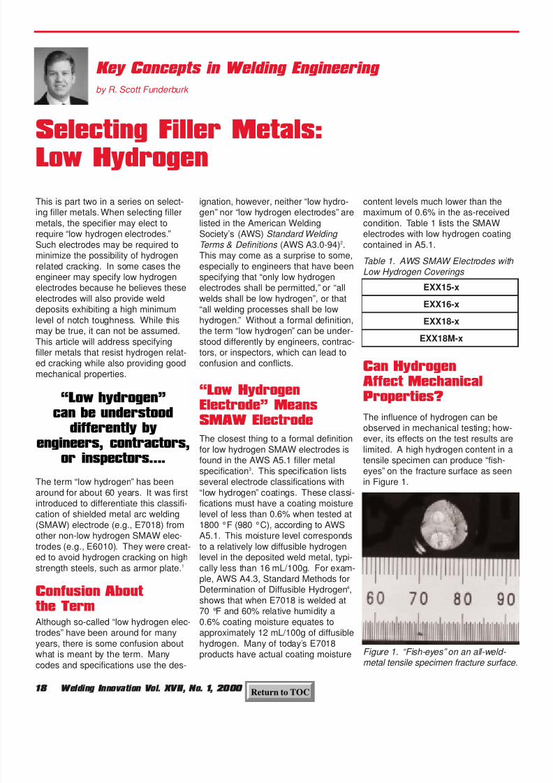
The influence of hydrogen can beobserved in mechanical testing; how-ever, its effects on the test results arelimited. A high hydrogen content in atensile specimen can produce “fish-eyes” on the fracture surface as seenin Figure 1.
Figure 1. “Fish-eyes” on an all-weld- metal tensile specimen fracture surface.
“Low hydrogen”
can be understooddifferently by
engineers, contractors,or inspectors….
Table 1. AWS SMAW Electrodes with
Low Hydrogen Coverings EXX15-x
EXX16-x
EXX18-x
EXX18M-x
Return to TOC

8/19/2019 Welding Innovation Vol. XVII, No. 1, 2000
http://slidepdf.com/reader/full/welding-innovation-vol-xvii-no-1-2000 21/28
Welding Innovation Vol. XVII, No. 1, 2000 19
Additionally, the presence of hydrogencan reduce ductility (as expressed byelongation and reduction in area).Hydrogen, however, does not typicallyinfluence the impact toughness, ultimatetensile strength or yield strength results.It is only in severe cases that it can
influence the ultimate tensile strength.
Since low hydrogen SMAW electrodeslike E7018 are also required to have a
minimum specified level of Charpy V-notch (CVN) impact energy, low hydro-gen is sometimes equated with aminimum CVN level. This has ledsome people to specify low hydrogenwhen the real desire is for notchtoughness. The better approach is tospecify notch toughness requirementssince there is no automatic linkbetween low diffusible hydrogen con-tent in the weld and CVN values.Actually, some deposits with highhydrogen levels can deliver relativelyhigh levels of notch toughness. Forexample, the E6010 classification(non-low hydrogen, 30-50 mL/100g)has a minimum CVN requirement of20 ft-lbs at minus 20°F.
Use of the Termin Codes andSpecifications
Some codes and specifications refer
to hydrogen control in terms of either(1) requiring low hydrogen SMAWelectrodes or (2) placing specific limitson diffusible hydrogen. The Structural Welding Code – Steel (AWS D1.1-2000)5 has provisions related to hydro-gen in the preheat table (Table 3.2). Inthe table, Category “A” is applicable to“shielded metal arc welding with otherthan low hydrogen electrodes.” Theminimum preheat temperatures listed
in Category “A” are higher thanCategory “B” because Category “B” isfor “shielded metal arc welding withlow hydrogen electrodes, submergedarc welding, gas metal arc welding,flux cored arc welding.”
In the Interim Guidelines: Evaluation,Repair, Modification and Design of Welded Steel Moment Frame
Structures 6 published by the FederalEmergency Management Agency(FEMA), a comparison between lowhydrogen SMAW electrodes andFCAW and SAW is made. This docu-ment states, “All of the electrodes thatare employed for flux cored arc weld-ing (both gas shielded and self shield-ed), as well as submerged arcwelding, are considered low hydro-
gen.” Implied is the assumption thatFCAW and SAW will provide welddeposits with diffusible hydrogen levelssimilar to SMAW electrodes with lowhydrogen coverings.
Weld DepositHydrogen LevelsAs mentioned above, no definitionexists for a “low hydrogen welddeposit.” The word “low” is an impre-cise description. The preferredmethod of controlling the level ofhydrogen in a weld deposit is to usethe optional hydrogen designators asdefined by the American WeldingSociety. These designators are in theform of a suffix on the electrode classi-fication (e.g., H8, H4, and H2). Thefiller metal manufacturer may chooseto add the hydrogen designator to theelectrode classification if the fillermetal meets the diffusible hydrogenrequirements in the applicable AWS
A5.x filler metal specification.Following are examples of the desig-nator requirements:
To avoid hydrogen induced cracking,the hydrogen level in the material mustbe held to a certain maximum level.This level is a function of themicrostructure susceptibility, constraint(or restraint), and residual stresses.Microstructure susceptibility to hydro-
gen induced cracking often increaseswith increasing steel strength.Therefore, for higher strength steelslower levels of hydrogen are required.To simply state “use low hydrogen” isnot enough. For example, “low” for a50 ksi steel may not be “low” for a 100ksi steel. Rather than require that “onlylow hydrogen electrodes can be used,”engineers and fabricators are shoulduse statements such as, “only elec-trodes or electrode-flux combinationscapable of depositing weld metal with a
maximum diffusible hydrogen content of8 mL/100g (H8) are permitted.”
Codes That UseHydrogen DesignatorsThe AWS D1.1 Structural WeldingCode also has several provisions thatutilize hydrogen designators (e.g., H8).For example, Category “D” in the mini-mum preheat and interpass tempera-ture table (Table 3.2) allows only“…electrodes or electrode-flux combi-nations capable of depositing weldmetal with a maximum diffusiblehydrogen content of 8 mL/100 g (H8).”This is a good example of properlyusing the H-designators.
The AWS D1.1 Code also has an
alternate method to determine theminimum preheat temperature (AnnexXI) that uses three levels of diffusiblehydrogen. In Annex XI, category H1 iscalled an “extra low hydrogen” at lessthan 5 mL/100g. Category H2 islabeled as “low hydrogen” at less than10 mL/100g. The third category, H3, isa hydrogen level that is not controlled.Although category H2 is labeled “lowhydrogen,” this does not define low
Table 2. Optional Hydrogen Designators
Diffusible Hydrogen,
mL/100g
H8 8
H4 4
H2 2
Hydrogen does nottypically influence the
impact toughness,ultimate tensile
strength or yieldstrength results
To simply state“use low hydrogen”
is not enough
Return to TOC

8/19/2019 Welding Innovation Vol. XVII, No. 1, 2000
http://slidepdf.com/reader/full/welding-innovation-vol-xvii-no-1-2000 22/28
20 Welding Innovation Vol. XVII, No. 1, 2000
hydrogen electrode as less than 10mL/100g. The actual diffusible hydro-gen value can also be used to calcu-late the minimum preheat temperaturewith this method instead of using theH1, H2 and H3 categories.
The Fracture Control Plan of the AWSBridge Welding Code 7 (AWS D1.5-95)is another fine example of hydrogencontrol. This code requires the follow-
ing for welding Fracture CriticalMembers:• H16, H8 or H4, when the minimum
specified yield strength is 50 ksi orless.
• H8 or H4, when the minimum speci-fied yield strength is greater the 50ksi.
Furthermore, SMAW electrodes canbe used for tack welding without pre-heat if the electrode has an H4 desig-nator, according to AWS D1.5.
Other agencies such as the UnitedStates Military8 and the AmericanBureau of Shipping9 also set limits onthe diffusible hydrogen levels. Bothuse limits of 15, 10 and 5 mL/100g,and the military specification has astricter limit of 2 mL/100g for someapplications. Today, a logarithmic sys-tem (i.e., H16, H8, H4, and H2) is pre-ferred in the United States.
Other IssuesUsing an H8, or even an H4, electrodewith controlled diffusible hydrogenalone provides no guarantee of elimi-nating problems related to hydrogenduring or after welding. In addition tothe electrode, several other factors caninfluence the diffusible hydrogen leveland the potential for cracking. Theseshould be considered as well.
• base metal surface condition (conta-mination from oils, grease, dirt,moisture, acid, rust and other hydro-gen containing materials canincrease hydrogen levels);
• relative atmospheric humidity (humidconditions generally lead to higher
hydrogen levels);• welding shielding gas (higher mois-
ture content results in higher hydro-gen levels);
• consumable storage conditions(improper or prolonged storage canlead to higher hydrogen levels);
• welding procedures (electrical stick-out, arc voltage, wire feed speedand other parameters can influencediffusible hydrogen).
Conclusions1.A “low hydrogen electrode” refers
only to a SMAW electrode that has acoating moisture of less than 0.6%.
2.The maximum diffusible hydrogenlevel associated with low hydrogenSMAW electrodes has been a pointof confusion because SMAW elec-trodes with low hydrogen coatingsare not tied to any specific hydrogenlevel.
3.“Low hydrogen” should not be speci-fied in order to achieve specificimpact properties. If notch tough-ness is required, then it should belisted separately from the hydrogenlimits (if any).
4.Job specifications should be writtenclearly and precisely regarding theuse of “low hydrogen.” The intent ofthe specifier should be listed in sucha way that the contractor will under-
stand what is required.
5.If a contractor has any questionsregarding in the intent of the engi-neer, or if the specifications are notclear, the contractor should seekclarification before welding. Forexample, if “use low hydrogen elec-
trodes only” is listed on the contract,then the contractor may want to ask:“Is only SMAW allowed, or can otherprocesses also be used?”
6.Supplemental hydrogen designators(e.g., H8 and H4) are the preferred
way to define a specific level of dif-fusible hydrogen in the weld depositand should be used when needed.
7.Finally, there are applications wherelow hydrogen electrodes are notrequired or where non-low hydrogenSMAW electrodes, like E6010, arepreferred. Therefore, utilizing theblanket statement “use low hydro-gen” should be avoided.
References1 Robert O’Con. “Welding with Low HydrogenElectrodes: A Look at the Past with Tips forToday.” Practical Welding Today. March/April2000, pp. 33-35.
2American Welding Society. Standard Welding
Terms and Definitions . (ANSI/AWS A3.0-94),1994.
3American Welding Society. Specification for
Carbon Steel Electrodes for Shielded Metal Arc Welding . (ANSI/AWS A5.1-91), 1994.
4American Welding Society. Standard Methods
for Determination of Diffusible Hydrogen
Content of Martensitic, Bainitic, and Ferritic Steel Weld Metal Produced by Arc Welding .(AWS A4.3-93), 1993, p. 16.
5 American Welding Society. Structural Welding Code – Steel . (AWS D1.1:2000), 2000.
6Federal Emergency Management Agency.
Interim Guidelines: Evaluation, Repair,Modification and Design of Welded Steel Moment Frame Structures . (FEMA 267),August 1995, p. 8-11.
7 American Welding Society. Bridge Welding Code . (AWS D1.5-95), 1995.
8
United States Military. Military Specification – Electrodes – Welding, Flux Cored, Ordinary Strength and Low Alloy Steel , (MIL-E-24403/1D), November 14, 1985.
9 American Bureau of Shipping. Rule Requirements for Materials and Welding,Part 2 , 1997.
Job specs shouldbe written clearly
and preciselyregarding the useof “low hydrogen”
Return to TOC

8/19/2019 Welding Innovation Vol. XVII, No. 1, 2000
http://slidepdf.com/reader/full/welding-innovation-vol-xvii-no-1-2000 23/28
21Welding Innovation Vol. XVII, No. 1, 2000
Here’s what past attendees have had to say about Lincoln Electric’sdesign seminars:
“Can’t say how much I appreciated this seminar. I would rate it a 10
on a 1-to-5 scale.”
“Not only did I get to learn about w elded design, but I got
to experience a company’s comm itment to excellence,
to employees, and to the industry.”
“Very informative. The pace was good. The facilit ies were excellent.”
“Would not be surprised if this was the best in the industry. First class.”
Blodgett’s Design of Steel StructuresBlodgett’s Design of Steel Structures is an intensive 3 day programwhich addresses methods of reducing costs, improving appearanceand function, and conserving material through the efficient use of welded steel in a broad range of structural applications. Seminarleaders: Omer W. Blodgett, Duane K. Miller, and R. Scott Funderburk.2.0 CEUs Fee: $595.
Blodgett’s Design of Steel WeldmentsBlodgett’s Design of Steel Weldments is an intensive 3 day programfor those concerned with manufacturing machine tools, construction,transportation, material handling, and agricultural equipment, as wellas manufactured metal products of all types. Seminar leaders: OmerW. Blodgett , Duane K. Miller, and R. Scott Funderburk . 2.0 CEUs.Fee: $595.
2001 dates will be posted on our website:www.lincolnelectric.com/services/educate/educate.asp
…as soon as they are available.
2001 Lincoln Electric Design Programs
Opportunities
Return to TOC

8/19/2019 Welding Innovation Vol. XVII, No. 1, 2000
http://slidepdf.com/reader/full/welding-innovation-vol-xvii-no-1-2000 24/28
Psst!
Pass It On….
22 Welding Innovation Vol. XVII, No. 1, 2000
Have you ever had a colleague or associate borrow your copy of Welding Innovationand fail to return it?
Have you ever read oneDuane Miller’s Design Filecolumns and thought,“Gee, I wish my boss
understood this” or“If only our clientunderstood thatconcept.”
Have you checkedout OmerBlodgett’s feature,new with thisissue, “LessonsLearned in theField”? Maybe you
know someone whocould share impor-tant knowledge gainedon the job. If so, Omerwould like to hear fromthat person.
Now it’s easier than ever to sendyour friends and associates their owncomplimentary subscriptions to WeldingInnovation. Or to change your address so that the
magazine will follow you to a new location. Or evento have a name taken off our subscription list if need be. Just log on to
www.lincolnelectric.com/services/educate/innovate.asp.
Don’t keep us a secret! Visit Welding Innovationonline, and “pass it on….”
Psst!
Pass It On….
Return to TOC
8/19/2019 Welding Innovation Vol. XVII, No. 1, 2000
http://slidepdf.com/reader/full/welding-innovation-vol-xvii-no-1-2000 25/28
Welding Innovation Vol. XVII, No. 1, 2000 23
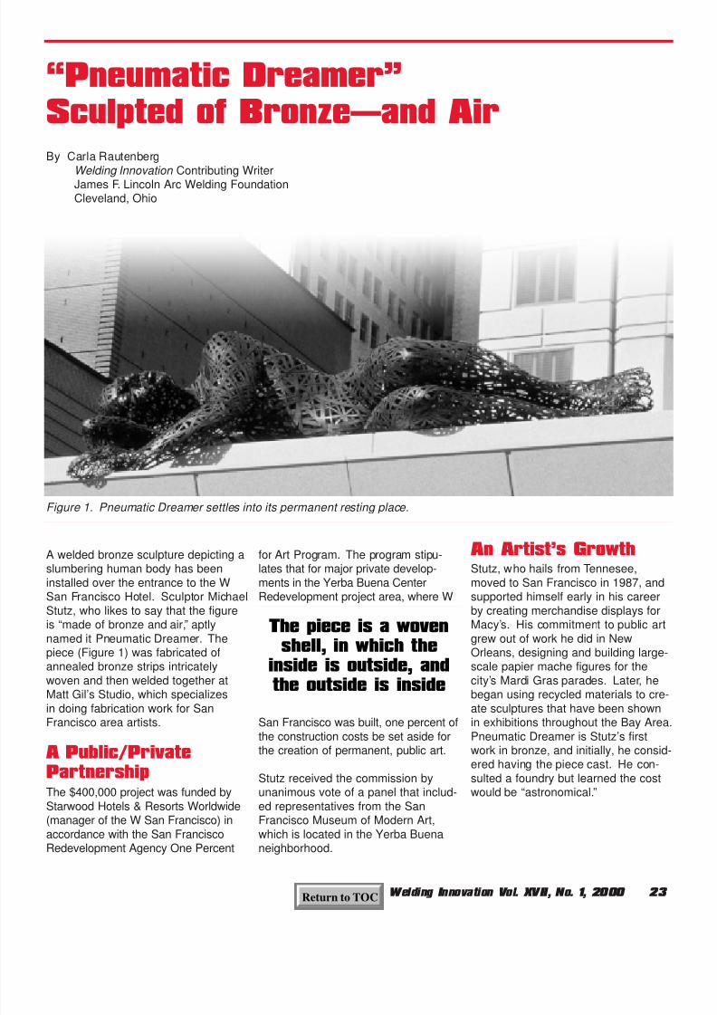
A welded bronze sculpture depicting aslumbering human body has beeninstalled over the entrance to the WSan Francisco Hotel. Sculptor MichaelStutz, who likes to say that the figureis “made of bronze and air,” aptlynamed it Pneumatic Dreamer. Thepiece (Figure 1) was fabricated ofannealed bronze strips intricatelywoven and then welded together atMatt Gil’s Studio, which specializes
in doing fabrication work for SanFrancisco area artists.
A Public/PrivatePartnershipThe $400,000 project was funded byStarwood Hotels & Resorts Worldwide(manager of the W San Francisco) inaccordance with the San FranciscoRedevelopment Agency One Percent
for Art Program. The program stipu-lates that for major private develop-ments in the Yerba Buena CenterRedevelopment project area, where W
San Francisco was built, one percent ofthe construction costs be set aside forthe creation of permanent, public art.
Stutz received the commission byunanimous vote of a panel that includ-ed representatives from the SanFrancisco Museum of Modern Art,which is located in the Yerba Buenaneighborhood.
An Artist’s GrowthStutz, who hails from Tennesee,moved to San Francisco in 1987, andsupported himself early in his careerby creating merchandise displays forMacy’s. His commitment to public artgrew out of work he did in NewOrleans, designing and building large-scale papier mache figures for thecity’s Mardi Gras parades. Later, hebegan using recycled materials to cre-
ate sculptures that have been shownin exhibitions throughout the Bay Area.Pneumatic Dreamer is Stutz’s firstwork in bronze, and initially, he consid-ered having the piece cast. He con-sulted a foundry but learned the costwould be “astronomical.”
“Pneumatic Dreamer”Sculpted of Bronze—and Air
Figure 1. Pneumatic Dreamer settles into its permanent resting place.
The piece is a wovenshell, in which the
inside is outside, andthe outside is inside
By Carla RautenbergWelding Innovation Contributing WriterJames F. Lincoln Arc Welding FoundationCleveland, Ohio
Return to TOC

8/19/2019 Welding Innovation Vol. XVII, No. 1, 2000
http://slidepdf.com/reader/full/welding-innovation-vol-xvii-no-1-2000 26/28
24 Welding Innovation Vol. XVII, No. 1, 2000
The sculpture was specificallydesigned for installation on the fourthfloor terrace of the neoclassical hotelbuilding, overlooking the street below(Figure 2). Stutz points out that thefigure, the gender of which is inten-tionally ambiguous, “could be goinginto a dream state, or arising from it”and that it illustrates “a very privatemoment in a very public space.” In
keeping with that idea, the piece is lit-erally a woven shell, in which, Stutzsays, “the inside is outside, and theoutside is inside.”
Pneumatic Dreamer is lit from both theinside and the front, emphasizing thewoven lattice aspect of the design. Itsbronze patina will weather to a green-ish-blue shade in about a decade.
The Fabrication
ProcessThe 30 ft (9,144 mm) long, 7 ft (2,134mm) high sculpture was too large tobe fabricated inside the shop at MattGil’s Studio. Thanks to the temperateclimate of the Bay Area, it was possi-ble to weld it in the yard outdoors. Gilnotes that “We had hoped to plug weldit from the outside, but that was going
to be too time-consuming and wouldhave left the surface blemished. So
we had to weld it from the inside.” Thework was accomplished by a team ofthree welders, three assistants, andthe artist, working together for 3-1/2months. Michael Stutz, while not awelder himself, put the 0.083 in. (21mm) thick bronze strips in place andserved as the “eyes” during fabrication.
Asked to describe the welding processitself, Matt Gil responds, “We usedMIG and standard heliarc TIG weldingwith a serium electrode. I weld bronzeusing AC and continuous high fre-quency as I would do for aluminum,but the use of the serium electrodewas unique.” All of the smallest parts(the fingers, toes, and face) had to be
TIG welded because that was the onlytool that could be manipulated in suchsmall spaces. The four mild steelstructural columns that support thesculpture were shop-fabricated usingLincoln 7018 electrode.
Stutz and Gil agree that the most diffi-cult aspect of fabricating the piece wasthe challenge posed by working insuch tight quarters. Gil says “We wereliterally working on top of each other.The welding was like stitching on theinside of the piece, while simultane-ously there were guys on the outsidedoing the weaving. The tediousnesswas a little unexpected.”
Although the soft and tactile appear-ance of Pneumatic Dreamer fittinglyechoes that of a sleeping human body,both Gil and Stutz were surprised atthe strength and rigidity of the finishedsculpture. When it was completed,Sheedy Crane & Rigging hoisted it outof the fabrication yard and it wastrucked to the Third Street location ofW San Francisco. Delighted pedestri-ans gawked as the sculpture was liftedinto the air and set onto its supportson the fourth floor terrace above. Likea contented hotel guest, the slumber-ing figure never stirred, but nestledcomfortably into place, dreaming allthe while.
Further information about MichaelStutz and his artwork is available onhis website at:
www.mdstutz.com
We were literallyworking on top of each
other…the tediousnesswas a little unexpected
Figure 2. The artist, Michael Stutz,in front of the entrance to San
Francisco’s W Hotel.
Return to TOC

8/19/2019 Welding Innovation Vol. XVII, No. 1, 2000
http://slidepdf.com/reader/full/welding-innovation-vol-xvii-no-1-2000 27/28
Welding Innovation Vol. XVII, No. 1, 2000 25Return to TOC

8/19/2019 Welding Innovation Vol. XVII, No. 1, 2000
http://slidepdf.com/reader/full/welding-innovation-vol-xvii-no-1-2000 28/28
P.O. Box 17035
Cleveland, Ohio 44117-0035
TheJames F. LincolnArc WeldingFoundation
NON-PROFIT ORG.
U.S. POSTAGE
PAID
JAMES F. LINCOLN
ARC WELDING FND.
This drill rig designed for Alaska's north slope received the Foundation's Best of Program Award.