Embed Size (px)
Citation preview
Spot Welding Aluminum 6022-T4 to Galvanized DP600 sheet by Refill
Friction Stir Spot Welding
Z. Shen1, J. Hou1, K. Chan2, N. Scotchmer2, N. Zhou1, A.P. Gerlich1
1. University of Waterloo, Mechanical and Mechatronics Engineering, Center for
Advanced Materials Joining, Waterloo, Canada
2. Huys Industries Ltd., Toronto, Canada
Abstract
Sheet metal welding in the automotive manufacturing industry is encountering increasing
challenges while joining light weight alloys. For some time, resistance spot welding (RSW) has
been the method of choice to join the vast array of automotive structural steels based on the
speed and low cost; however, new combinations of non-ferrous materials suffer from limited
weldability by RSW. Specifically, aluminum sheet metals offer many desirable properties for use
in sub critical components such as body skins or brackets and latches, and advanced high
strength steels are becoming commonplace for components requiring extremely high strength
for rigidity and crashworthiness. However, joining these two dissimilar metals to each other
presents a challenge for manufacturing. The present work examines Refill Friction Stir Spot
Welding (RFSSW) to join aluminum sheet to zinc coated steel. Joints were made without
melting of either of the base materials utilizing the plastic flow of the aluminum sheet to
generate pressure and heat during welding. Weld parameter testing along with metallography
including SEM/EDX analysis was performed to investigate the joining mechanism and define an
operational window which can meet overlap shear fracture load requirements of AWS standards.
Keywords: AL6022-T4, DP600, Refill Friction Stir Spot Weld, Dissimilar Joint
Introduction
With stringent government standards targeting reduced carbon emissions, vehicle light
weighting in conjunction with engine downsizing is a popular solution to reduce emissions. As a
result, there has been an increase in the application of light weight alloys in automotive
structures to reduce overall mass of the vehicle. The use of aluminum and magnesium alloys for
components such as body skins, brackets, sub-frames and latches, coupled with advanced high
strength steel (AHSS) for structural components are becoming commonplace. Traditionally,
resistance spot welding (RSW) has been the prime choice for joining automotive sheet metals;

however, RSW can no longer effectively produce structurally sound joints with the introduction
of incompatible and novel material combinations due to their physical and chemical properties,
especially the differences in melting temperatures and mutual solubility. Additionally, severe
heating and cooling cycles from fusion welding can cause weld defects such as cracking,
porosity, and bulk intermetallic compound (IMCs) formations, many of which are detrimental to
weld integrity and strength [1, 2]. This motivates the application of solid state joining
technologies, such as friction welding [3], ultrasonic spot welding [4], friction stir welding [5], as
well as friction stir spot welding to be potential to replacement of resistance spot welding (fusion
welding) in joining these combinations of non-ferrous and ferrous materials [6]. The main
advantage of solid state joining technology is minimized energy input, which limits the formation
of bulk IMCs, thermal distortion and residual stresses [7].
The present study focuses on the application of refill friction stir spot welding (RFSSW). This
process was developed by Helmholtz-Zentrum Geesthacht in Germany in 1999 to achieve a
larger effective bonded region and higher weld strength compared to conventional FSSW
(without the refill capability) [8]. In conventional FSSW, a single piece tool (with only a cylindrical
should and pin feature) is only plunged and retracted from the sheets in two steps. In contrast,
RFSSW uses a tool with multiple pieces in four steps, summarized in Figure 1. In the first stage
shown in Figure 1a, the tool used in RFSSW comprises a stationary clamp ring, an external
sleeve and an internal pin. The role of the clamping ring is to hold the workpieces firmly in
contact during the welding process, and prevent the sheets from lifting and separating as the
plasticized material is displaced by the pin and sleeve. The sleeve and pin rotate together while
able to advance and retract independently, operated by servo-actuators. The joint forms by
plasticizing, and displacing the material in a process similar to back extrusion, and the refill
FSSW process can be divided into two variants (pin plunge variant and sleeve plunge variant).
So far, the sleeve plunge variant is the most commonly used variant, since it produces a larger
effective welded area, but this variant demands higher plunge force [9]. The sleeve variant
RFSSW process is schematically shown in Figure 1a-d, which has already been described in
detail in the prior literatures [10, 11, 12].
Figure 1: Schematic of the Refill Friction Stir Spot Welding Process (Sleeve Plunge Variant)
Tool wear in conventional non-refill FSSW is reportedly much more excessive compared to that
in linear FSW since wear mainly occurs in the tool plunge period [13], however 100,000 welds
can still be achieved without degradation in joint strength in aluminum sheet welds [14]. For
dissimilar metal joints in RFSSW, in order to obtain mechanical interlocking by displacing the

bottom ferrous material into the upper lightweight material sheet, it is necessary to plunge the
tool pin into the bottom sheet. This would require an advanced tool material, such as W–25 wt-
%Re or WC-Co to be used [6, 15]; however, such materials are not currently available for
RFSSW tooling. Previous research has shown that acceptable joint strengths can be achieved
by purely metallurgical or diffusion bonding mechanisms, with the lightweight alloy sheets set as
the top sheet when joining to a harder material. In this case, the tool plunge depth could be
carefully controlled to avoid direct contact of the tool into the bottom steels, making it possible to
use a tool made of common tool steels, and maintains the flat interface profile between the
sheets [16, 17, 18, 19, 20, 21]. In these cases, the tool penetration depth is the most influential
factor for weld integrity and strength. For example, Lee et al. [19] found that the weld strength
increased with increasing tool penetration in the top Al alloy, but excessive tool penetration
caused defects and deformation of the top Al alloy sheet. The presence of a zinc coating on
galvanized steel surface can promote the formation of Al–Zn or Mg-Zn eutectic structure at the
interface, which is believed to be beneficial to the bonding formation and weld strength. Ibrahim
et al. [20] reported that Zn coating was melted or softened and circumferentially re-solidified
around the nugget, and IMCs were formed along the interface resulting in the joining of Al or Mg
to steel. Al/steel weld showed poor fatigue strength since circumferentially re-solidified Zn
brought about the stress relaxation at the edge of the Al/galvanized steel nugget. Shen et al. [17]
found the static and fatigue performance of Mg/steel dissimilar refill friction stir spot weld can be
enhanced by the brazing around the weld boundary, and the brazing effect was derived from the
zinc coating on the steel surface.
The present study focused on the investigation of aluminum to galvanized steel sheet dissimilar
RFSSW welds. Optimization of welding parameters, and evaluation of interfacial bonding,
thermal cycle and mechanical properties, was performed to evaluate the role of tool temperature.
This preliminary research serves as a starting point for further optimization of parameters to
maximize joint strength in tools with supplemental cooling.
Experimental Procedure
Materials
The base materials used for the present study are 1.6mm thick AA6022-T4 (top sheet) and
2.0mm galvanized (zinc coated) DP600 steel sheets (bottom sheet). Table 1 summarizes the
chemical composition of the sheet metals used.
Table 1: Material Chemical Composition
Coating Base Metal, wt-%
Mat Thickness
[mm]
Al Cr Cu Mg Mn Si Ti Zn Fe
AA6022-
T4 1.6 None Remainder 0.1
0.01-
0.11
0.45-
0.070
0.02-
0.10
0.80-
1.5 <0.15 <0.25
0.05-
0.20
Fe C Mn Si P S Cr+Mo+Ni
DP600 2 GI Remainder 0.14 2 1.5 0.04 0.015 1

Characterization of the galvanized DP600 sheets was performed to examine the zinc coating
thickness, which was found to be an average of 6.5 µm. The measured coating thickness is
considered very thin and can be easily disturbed by the stirring action of the welding process,
hence additional consideration of welding parameter selection was taken into account. The
AA6022 and DP600 steel coupons were cleaned with ethanol before the welding process. Test
specimens were fabricated with two 30mm×100mm coupons overlapped by 30mm, and the
welds were made at the center of the overlapped area according to the American Welding
Society (AWS) standard D 17.2 [22].
Welding Setup
The welding in the present study was conducted using a Harms & Wende RPS100 refill friction
stir spot welding machine. The system consists of the 3-piece weld tool; the stationary clamping
ring and a pair of rotating and vertical shifting sleeve and pin. The diameter of the clamp ring,
sleeve and pin are 15, 9 and 6 mm, respectively. The welding process sequences consists a
combination of tool rotation and penetration depth as well as a series of sequence timings; pre-
heat, plunge, dwell, retract, and post heating dwell time. Depending on the contribution of
parameters towards energy input at the weld interface, ultimately controlling the corresponding
weld performance. Two main welding parameters, plunge depth and dwell time, were found to
be particular influential to weld strength for dissimilar welding. As such, these two parameters
varied, while the remaining control parameters were constant. The welding parameters used are
summarized in Table 2
Table 2: Weld Schedule Selection Matrix
Welding Parameter Selection Matrix
Spindle Rotation Speed [RPM]: 1800
Surface Friction Dwell Time [s] 0.5
Plunge Time [s] 0.207
Plunge Depth [mm] 0.8-1.4 (50-87.5% sheet thickness)
Stirring Dwell Time [s]
1, 2, 3
Tool Retract Time [s] 0.5
Surface Dwell Time After Retraction [s] 0.25
Temperature Measurement Setup
Preliminary welding trials of AA6022 to DP600 indicated that high welding temperatures (energy
input) resulting from both high plunge depth (95% aluminum sheet thickness) and long dwell
time (>3 seconds) resulted in low strength or negligible bonding. Two explanations account for
the unbonded conditions with the particular welding parameters: excessive disturbance of the
zinc coating from physical stirring, and excessive heating of the interface. High weld interface
temperatures, specifically beyond the 94% Zn-Al eutectic point of 381oC (based on the binary
phase diagram [23]), can result in zinc liquidation and oxidation, leading to poor weld strength.
As a result, the tool and weld interface temperature control was of high importance for this study.

In order to better control tool temperature for sequential welding, a prototype water cooled
copper cooling block was fabricated and attached to the outer surface of the clamping ring tool.
The cooling block was used concurrently with the standard tool cooling circuit, which employs a
thin copper conductive cooling sleeve in the clamp. Thermal measurements of the tool clamp
were acquired by welding a K-type thermocouple to the outer boundary of the clamp ring as
indicated in Figure 2a and b, at a location 5mm away from the end of the tool. The interface
temperature acquired by sandwiching a thin K-type thermocouple within a machined out groove
between the weld interface Figure 2c. Thermal measurements were acquired with National
Instruments 9213 DAQ system.
Figure 2: Spot welder setup: a) external tool shoulder cooling circuit and temperature acquisition setup, b) tool shoulder cooling
block and thermocouple setup and, c) thermocouple placement within grooved out steel plate
Tensile Testing Setup
Tensile testing was performed in lap-shear setup with a constant cross head speed of 10mm
min-1, as recommended by AWS D8.2M:2007 standard [24]. All tensile coupons were cut to
30x100mm with the rolling direction parallel to the longer side and the weld situated in the
center of 30x30mm overlapped region (Figure 3). Since the weaker material for the weld
combination is the AA6022-T4 material, the minimum required shear strength was calculated
based on the AWS standards, as 3.87kN [24].
Water Chiller
Weld Head
K-type Thermocouple DAQ
Weld Table
a b
Clamping Ring Cooling Block
K-Type Thermocouple
K-Type Thermocouple
c)
DP600 Sheet
AA6022 Sheet

Figure 3: Weld specimen setup for tensile lap shear testing and characterization
Characterization Setup
The welds are sectioned through the weld center, and prepared using standard metallographic
techniques with a final polishing with 3µm diamond. The microstructure characterization and
chemical analysis were conducted by using a JEOL JSM-6460 scanning electron microscope
(SEM) operated at 20kV accelerating voltage equipped with an ENCA 3.5 energy dispersive X-
ray (EDX) analysis system. The lap shear tensile tests were performed at a rate of 10mm/min
by using a Tinius Olsen (H10KT) tensile testing machine. All of the strength values were
obtained by averaging the strengths of three individual specimens made at the same welding
condition.
Results and Discussions
Parameter Optimization and Tensile Properties
Each combination of welding schedule summarized in Table 2 was welded with three repetitions
and tensile tested for weld strength. Figure 4 illustrates the all of the weld strengths against
recorded maximum tool temperatures of each weld, separated with three different dwell times
regardless of different plunge depths. It should be noted each weld was conducted at a similar
starting temperature of 55 +/- 5oC for weld consistency. Welds performed with 1s dwell time
resulted in fracture strengths mainly from 2.5 to 4kN, with a few exceptions reaching to 5kN. As
the dwell time increases from 2s to 3s, the maximum tool temperature recorded increases as
well. When a 2s dwell time is applied the welds performed much better, with more welds
exceeding the minimum requirement of 3.87 kN [24]. When a 3s dwell time is applied, the welds
performed with strengths capable reaching as high as 6.23kN. However, when the tool
temperatures during welding approach 350oC, the weld strength plummets well below the
minimum requirement.

Figure 4: Weld Parameter Optimization Plots: a) tool temperature to weld strength influence plot and
Three representative welds based on tooling temperature, designated as insufficient, acceptable,
and overheated welds, were selected from the weld parameter matrix. Weld strengths and
clamping ring maximum temperatures for each representative welds are summarized in Table 3.
As previously noted, the integrity of the welds is governed by the temperature and energy input
from the weld schedules. With insufficient energy input, the maximum tool temperature reached
was 179oC and the weld strength achieved was below the minimal requirement of 3.87kN. With
sufficient energy input, the weld strengths exceed and nearly doubles the minimal required
strength, while the tool temperature reaches 298oC. Finally, when overheating occurs with an
overshoot of energy input, tool temperatures reach 335oC and the weld strengths plunge below
acceptable levels.
Table 3: Representative weld parameter data
Condition Insufficient Sufficient Overheated
Dwell Time [s] 1 3 3
Plunge Depth [mm] 0.8 1 1.4
Repetition Fracture Force [kN]
1 2.86 5.09 3.31
2 3.11 5.37 1.99
3 2.55 6.23 2.72
Average 2.84 5.56 2.67
Max Tool Temp 179 298 335
Each weld condition produces distinct appearances when observing weld fracture interfaces
(Figure 5). When sufficient energy is provided, the weld interface presents with a combination of
a white and grey ring appearance Figure 5a. The white artifact in the weld center occurs when
the welds are subjected to high temperatures, while the grey artifact is a result of zinc IMCs with
0
1
2
3
4
5
6
7
150 200 250 300 350
Fra
ctu
re F
orc
e [
kN
]
Tool Surface Temp [C]
1 Second Dwell Time 2 Second Dwell Time
3 Second Dwell Time Min Fracture Force

the aluminum. Due to the nature of zinc coating during the welding process, a large amount of
zinc coating migrates towards the weld center as the sleeve plunges into the aluminum sheet.
During the sleeve plunging process, a slight imbalance of temperature present within the weld
interface between the pin and sleeve area. The upper layer of zinc experiences high
temperature from the stirring effect from the sleeve and migrates towards the weld center, while
the bottom layer of zinc experiences sufficient temperatures to begin brazing or possibly
diffusion bonding. When insufficient energy is provided to the weld, diffusion bonding does not
happen between zinc and aluminum. As a result, the weld interface has a shiny aluminum
appearance as shown in Figure 5b. At the other extreme, when too much energy is applied, the
entire weld interface appearance of the fracture surface is almost entirely white Figure 5c.
Figure 5: Fracture Interface Appearance: a) Optimal Heat (6.23kN @ 298oC), b) Insufficient Heat (2.86kN @ 179
oC), and c)
Overheated (1.99kN @ 335oC)
Optical and Scanning Electron Microscopy
Figure 6a and b reveal the weld surface appearance and optical macrostructure of the weld
made with acceptable energy input welding conditions, involving 1800RPM summarized in
Table 3. The weld surface appears shiny and uniform with the original workpiece surface. As
shown in Figure 6a, an annular indent imposed by the clamp ring was formed around the weld,
which is slightly past the weld surface. As indicated in below Figure 6b, the weld boundary was
marked by black lines, and voids can be observed within the weld boundary. The Al/steel
interface is comparatively uniform, no macro-scale plastic deformation can be observed, and the
top aluminum alloy sheet was imposed onto the bottom DP steel sheet by the welding tool.
However, micro-scale cracking was noted at the Al/steel interface. The current study does not
a)
b)
c)
AL
AL
AL
DP
DP
DP

provide the microstructure details of the top Al sheet, since the previous research showed that
the upper sheet microstructure scarcely affects the weld strength when interfacial fracture
dominates [15, 16].
Figure 6: Optical Micrographs of Al-DP Welds: a) Weld surface appearance and b) Weld cross-section produced using 1800 RPM,
1.0mm penetration, and a 3s dwell time
Figure 7a-c illustrates SEM micrographs at locations A and C indicated in Figure 6b. As
illustrated in these figures, the zinc coating thickness distribution is not uniform, ranging from 0.5
to 3.2 um at locations A and B, and around 20um at the weld center in Location C. It can be
observed that the zinc coating under the sleeve shifted into the weld center due to a cylindrical
cavity that was created during the sleeve plunge and pin retreat phase. Furthermore, the
bonding has occurred under the sleeve before the sleeve moves upward and pin moves
downward, which promoted displaced zinc coating to be entrapped in the weld center. As shown
in Figure 7a, cracking can be observed at the boundary of sleeve and pin, whose direction is
consistent with the material flow. The chemical compositions in the locations A-F were
quantified in Table 4, where the zinc content ranged from 16.9 to 19.5%, and the iron content
ranged from 0.5% to 2.9%. Meanwhile, cracking can be observed in Figure 7b. The chemical
compositions in locations of (i) through (vii) were quantified in Table 4 where the zinc content
ranged from 18.6% to 24.3%, and the iron content ranged from 0.8% to 2.3%. It can be
concluded that the zinc penetrated into the top Al alloys along the grain boundary, which is
caused by high temperature and upward motion of material flow imposed by the tool. As noted
previously [23], Al-Zn low melting point eutectic structure could be formed at the temperature of
351oC, and the maximum tool temperature reaches 335oC (see Figure 4). Prior work by
Suhuddin et al. and Shen et al. showed the maximum temperature can reach 450oC and 501oC,
respectively [12, 25], which readily explains the formation of Al-Zn eutectic structure. It also can
be believed that IMCs of Al-Fe also can be formed in these locations, which has been confirmed
by Chen et al. that continuous layer of FeAl2 particles, which appeared to originate from the zinc
coating on the DP600 steel surface [16].
a b)

Figure 7: SEM Micrographs of locations (a) A and (b) location C in Figure 6b.
Table 4: EDX Chemical Composition Quantification Results (wt%) indicated in Figure 7.
Spectrum Al Fe Zn Total
i 82.2 0.5 17.3 100
ii 81.5 0.8 17.7 100
iii 82.4 0.7 16.9 100
iv 79.0 1.6 19.4 100
v 77.6 2.9 19.5 100
vi 80.1 2.3 17.6 100
vii 73.4 2.3 24.3 100
Thermal Studies of AA6022-T6 to DP600 Dissimilar RFSSW Welds
Consecutive Welding Trials – Additional Cooled VS Stock Cooling
The high tendency for tool overheating observed during the preliminary trials in this study
suggests that control of the tool temperature is critical for the process to be used in an industrial
setting. As a result, an additional cooling collar was fabricated and attached to the clamping ring
in order to improve heat extraction and prevent overheating and weld separation as discussed
earlier. A comparison of the standard cooled and externally cooled clamping ring was conducted
to test the stability of the weld strengths in sequential welding. Welds were made with a
satisfactory welding schedule summarized in Table 3. Figure 8 summarizes the comparison
data between stock cooling (Figure 8a) and additional cooling (Figure 8b) trials. The welds were
conducted at 10s intervals to allow for constant cooling time between welds, which is the most
practical repetition speed achievable in manually repeated experiments. The welds with the
a b)
i
ii iii
iv
v
vi
vii

additional cooling heatsink on the tool clamp outperform the standard cooled tooling welds by a
margin of only 3 consecutive welds; however, the overall weld strengths of the additionally
cooled case were much higher by an average difference of 2.24kN. Weld strengths tended to
increase for the first 5 welds for both cases. While the maximum weld strength peaked at
6.32kN for the 5th weld using the standard tooling, the weld strength continued to increase for
the additionally cooled tool, peaking at 7kN for the 7th weld. It can be noted that in both
scenarios, the weld force drastically decreased once the tool temperature reaches 350oC and
subsequent welds at higher tool temperatures, and failed to produce suitable welds.
Figure 8: Overlap fracture load measurements for consecutive welding trials with and without additional cooling.
Interface Temperature Measurement
Based on the thermal and weld strength results in the consecutive welding trials, a large window
of acceptable tool temperatures exist between the first weld to the breaking point at 350oC. With
each subsequent weld, the pre-weld temperature of the tool increased up to the critical
temperature where satisfactory welds are no longer achievable. It can be assumed that the
temperature at the weld interface would be much greater than the tool surface temperature. This
raises the question of the correlation between the specific weld interface temperatures at
different pre-weld temperatures of the tool, and how this would affect weld strength. For
example, the thermal profile of a subsequent weld, when a 150oC pre-heat was applied to the
tool is illustrated in Figure 9. The preheat energy was applied using a previous weld cycle. The
peak weld interface temperature reached 389oC, just below the 94% Zn-Al eutectic temperature,
while the maximum tool temperature reached 216oC. The final weld strength is thought to be
based on the formation of the Zn-Al eutectic, however the peak temperature and pre-heat
temperature relation is not fully characterized. Based on the thermal and weld strength results in
the consecutive welding trials, a window of acceptable weld strength is available between the
first weld up to the breaking point at a tool temperature of 350oC. The interfacial temperature
measurement trials were conducted with the 1mm plunge and 3s dwell weld parameter.
0
1
2
3
4
5
6
7
8
1 2 3 4 5 6 7 8 9 10 11 12 13 14 15
We
ld F
ract
ure
Fo
rce
[k
N]
Weld Number - 10s Interval
Additional Cooling Stock Cooling Min Fracture Force
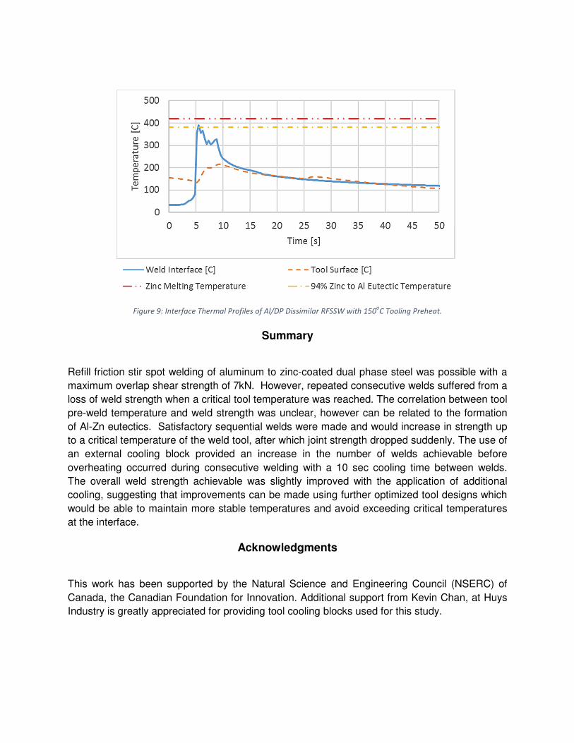
Figure 9: Interface Thermal Profiles of Al/DP Dissimilar RFSSW with 150oC Tooling Preheat.
Summary
Refill friction stir spot welding of aluminum to zinc-coated dual phase steel was possible with a
maximum overlap shear strength of 7kN. However, repeated consecutive welds suffered from a
loss of weld strength when a critical tool temperature was reached. The correlation between tool
pre-weld temperature and weld strength was unclear, however can be related to the formation
of Al-Zn eutectics. Satisfactory sequential welds were made and would increase in strength up
to a critical temperature of the weld tool, after which joint strength dropped suddenly. The use of
an external cooling block provided an increase in the number of welds achievable before
overheating occurred during consecutive welding with a 10 sec cooling time between welds.
The overall weld strength achievable was slightly improved with the application of additional
cooling, suggesting that improvements can be made using further optimized tool designs which
would be able to maintain more stable temperatures and avoid exceeding critical temperatures
at the interface.
Acknowledgments
This work has been supported by the Natural Science and Engineering Council (NSERC) of
Canada, the Canadian Foundation for Innovation. Additional support from Kevin Chan, at Huys
Industry is greatly appreciated for providing tool cooling blocks used for this study.

References
[1] K. Miyamoto, S. Nakagawa, C. Sugi, H. Sakurai and A. Hirose, "Dissimilar joining of aluminium alloy and steel
by resistance spot welding," SAE International Journal of Materials and Manufacturing, vol. 2, no. 01-0034, pp.
58-67, 2009.
[2] L. Agudo, D. Evidi, C. H. Schmaranzer, E. Arenholz, N. Jank, J. Bruckner and A. R. Pyzalla, "Intermetallic Fe x Al
y-phases in a steel/Al-alloy fusion weld.," Journal of materials science, vol. 42, no. 12, pp. 4205-4214, 2007.
[3] M. Yilmaz, M. Col and M. Acet., "Interfaces properties of aluminium/steel friction-welded components,"
Materials Characterization, vol. 49, no. 5, pp. 421-429, 2002.
[4] F. Haddadi, D. Strong and P. B. Prangnell, "Effect of zinc coatings on joint properties and interfacial reaction
sin aluminium to steel ultrasonic spot welding," JOM, vol. 64, no. 3, pp. 407-413, 2012.
[5] T. DebRoy and H. K. D. H. Bhadeshia, "Friction stir welding of dissimilar alloys - a perspective," Science and
Technology of Welding & Joining, 2013.
[6] T. Liyanage, J. Kilbourne, A. P. Gerlich and T. H. North, "Joint formation in dissimilar Al alloy/steel and Mg
alloy/steel friction stir spot welds," Science and Technology of Welding and Joining, vol. 14, no. 6, pp. 500-508,
2009.
[7] Z. Shen, Y. Chen, M. Haghshenas and A. P. Gerlich, "Role of welding parameters and interfacial bonding in
dissimilar steel/aluminium friction stir welds," Engineering Science and Technology, an International Journal,
vol. 18, no. 2, pp. 270-277, 2015.
[8] C. Shilling and J. d. Santos.Washington DC: U.S. Patent and Trademark Office Patent 6,722,556, 2004.
[9] S. T. Amancio-Filho, A. P. Camillo, L. Bergmann, J. F. D. Santos, S. E. Kury and N. G. Machado, "Preliminary
investigation of the microstructure and mechanical behaviour of 2024 aluminium alloy friction spot welds,"
Materials Transactions, vol. 52, no. 5, pp. 985-991, 2011.
[10] T. Rosendo, B. Parra, M. A. D. Tier, A. A. M. D. Silva, J. F. D. Santos, T. R. Strohaecker and N. G. Alcantara,
"Mechanical and microstructural investigation of friction spot welded AA6181-T4 aluminium alloy," Materials
& Design, vol. 32, no. 3, pp. 1094-1100, 2011.
[11] Z. Shen, X. Yang, Z. Zhang, L. Cui and T. Li, "Microstructure and failure mechanisms of refill friction stir spot
welded 7075-T6 aluminium alloy joints," Materials & Design, vol. 44, pp. 476-486, 2013.
[12] Z. Shen, Y. Chen, J. S. C. Hou and A. P. Gerlich, "Influence of processing parameters on microstructure and
mechanical performance of refill friction stir spot welded 7075-T6 Aluminium Alloy," Science and Technology
of Welding and Joining, vol. 20, no. 1, pp. 48-57, 2015.
[13] T. J. Lienert, J. W. L. Stellwag, B. B. Grimmett and R. W. Warke, "Friction stir welding studies on mild steel,"
Welding Journal - New York, vol. 82, no. 1, pp. 1-5, 2003.
[14] J. Hinrichs, C. Smith, B. Orsini, R. DeGeorge, B. Smale and P. Ruehl, "Friction Stir Welding for the 21st Century
Automotive Industry," in 155th FSW Symposium, Waukesha, WI USA.
[15] A. A. M. D. Silva, E. Aldanondo, P. Alvarez, E. Arruti and A. Echeverria, "Friction stir spot welding of AA 1050 Al
alloy and hot stamped boron steel (22MnB5)," Science and Technology of Welding and Joining, 2013.
[16] Y. Chen, J. Chen, B. S. Amirkhiz, M. J. Worswick and A. P. Gerlich, "Microstructures and properties of Mg
alloy/DP600 steel dissimilar refill friction stir spot welds," Science and Technology of Welding and Joining, vol.
20, no. 6, pp. 494-501, 2015.
[17] Z. Shen, Y. Ding, J. Chen and A. P. Gerlich, "Comparison of fatigue behaviour in Mg/Mg similar and Mg/steel

dissimilar refill friction stir spot welds," International Journal of Fatigue, vol. 92, pp. 78-86, 2016.
[18] Y. Uematsu, T. Kakiuchi, Y. Tozaki and H. Kojin, "Comparative study of fatigue behaviour in dissimiar Al
alloy/steel and Mg alloy/steel friction stir spot welds fabricated by scroll grooved tool wtihout probe," Science
and Technology of Welding and Joining, vol. 17, no. 5, pp. 348-356, 2012.
[19] Y. C. Lee, D. H. Choi, Y. M. Yeon and S. B. Jung, "dissimilar friction stir spot welding of low carbon steel and Al-
Mg alloy by formation of IMCs," Science and Technology of Welding and Joining, 2013.
[20] I. Ibrahim, Y. Uematsu, T. Kakiuchi, Y. Tozaki and Y. Mizutani, "Fatigue behaviour of dissimilar Al
alloy/galvanized steel friction stir spot welds fabricated by scroll grooved tool without probe," Science and
Technology of Welding and Joining, vol. 20, no. 8, pp. 670-678, 2015.
[21] E. Fereiduni, M. Movahedi and A. H. Kokabi, "Dissimilar Al/steel friction stir spot welding: To penetrate into
lower steel sheet or not?," Science and Technology of Welding and Joining, pp. 1-7, 2016.
[22] American Welding Society, AWS D17.2 Specification for resistance welding for aerospace applications, AWS,
2007.
[23] ASM International, "Al (Aluminium) Binary Alloy Phase Diagram," in ASM Handbook Volume 3 - Alloy Phase
Diagrams., ASM International, 1992, pp. 2.4-2.56.
[24] A. D. C. o. A. Welding, AWS D81M:2007 Specification for Automotive Weld Quality - Resistance Spot Welding
of Steel, Miami, FL: American Welding Society, 2007.
[25] U. F. H. F. V. &. D. S. J. F. Suhuddin, "The thermal cycle during the dissimilar friction spot welding of aluminum
and magnesium alloy," Scripta Materialia, vol. 68, pp. 87-90, 2013.


![Maximizing Strength of Friction Stir Spot Welded ...d.researchbib.com/f/8nnKOup2bho3WaY0yWFx1SY1... · recent times to weld aluminum alloys [5], [6], [7]. Friction stir spot welding](https://img.dokumen.tips/doc/110x75/5f099a157e708231d4279dfb/maximizing-strength-of-friction-stir-spot-welded-d-recent-times-to-weld-aluminum.jpg)