Embed Size (px)
Citation preview
•
205C.25
Welded Continuous Frames and Their Components
PLASTIC ANALYSIS OFTAPERED HAUNCHED CONNECTIONS
by
John W. FisherGeorge Co Lee
GeorgeC. Driscoll, Jr.
This work has been carried out as a part of an investigation sponsored jointly by the Welding Research Council andthe Department of the Navy with fun~s furnished by the·following:
American Institute of Steel ConstructionAmerican Iron and Steel InstituteInstitute of Research, Lehigh UniversityOffice of Naval Research (Contract Nonr61003)Bureau of Ships ..Bureau of Yards and Docks
Reproduction of this report in whole or in part ispermitted i'0F any purpose of the United States Government 0
Fritz Engineering LaboratoryDepartment of Civil Ehgineering
Lehigh UniversityBethlehem, Pennsylvania
.... '~ . ~ .; ."'.'
September 1961
Fritz Engineering Laboratory Report No. 205c.25
.-
"
.205C.25
ABSTRACT
A method is ,presented for· analyzing connections' with
tapered haunched, flanges commonly used in rigid frame con
struction. The method is based on simple plastid Jtheory.
The equations for the required bending capacity' are derived.
The effect of axial force and shear upon the full plastic
moment of a section having non-parallel flanges is studied.
Also, the lateral and torsional stability of the compression
flange of the connection is considered.
Design procedures for proportioning a connection with
non-parallel flanges are presented 3 including procedures for
the design of the stiffenerso The design of a corner
connection for a gabled frame is used to illustrate the pro
cedures.
,
205C 0 25
CONTENTS
10 INTRODUCTION
101 Objectives1 0 2 Previous Research
2{0 PLASTIC ANALYSIS
201 Solution by Simple Plastic Theory2 0 2 Influence of Axial Thrust203 Influence of Shear204 Location of Critical Section in the Haunch
3. STABILITY OF THE COMPRESSION FLANGE
Page
1
12
5
571013
17
40 DESIGN RECOMMENDATIONS AND DESIGN EXAMPLE,
301302
303
304
Solving the DiffsrentialEquations of BucklingIncreasing the Critical Buckling Length by
Controlling the StrainsIncreasing the Critical Buckling Length by In
creasing the Haunch Angle pReinforcing the Knee
1720
')3I~
24
30
.'
401 Recommended Design Procedure40 2 Design Example
5" SUMMARY AND ,CONCLUSIONS
60 ACKNOWLEDGEMENT
7" NOMENCLATURE
80 FIGURES
9 0 REFERENCES
3032
39
•
10 INTRODUCTION
101 ObJectives
Savings of 10 to 12% in the weight of main members of
a portal frame may be made by using haunched connections in
elastic design rather than using a straight connection designSl)
Furthermore~ a haunched connection has a more pleasing appear
anceo For these reasons~ haunched connections are widely used~
particularly in long=span frameso Since a complete elastic
analysis is complex and time=consuming, a simple~ accurate
yet economical method of proportioning haunched connections
1s desirab1e o The use of plastic analysis and design will
make it possible to meet this objective as well ~s retain the
advantages of weight=saving and appearance o It is the purpose
of this study to present an analysis of and to make recommen-
dations for plastic design of tapered haunched connections of,
structural steelo
The objectives of this study are summarized as follows~
(1) To analyze theoretically the effect of axial force
and shear upon the full plastic moment of sections having.
non=paralle1 flangeso
(2) To analyze theoretically the lateral instability of
the compression flanges of haunched connections at which plastic
hinges form in a structureo
(3) To formulate specific recommendations suitable for
use in plastic design which will enable the use of haunched
connections as component parts of a steel frame in an econo-
mical and safe mannero
102 Previous Research
Corner connections for use ~n rigid frames can generally
be classified into three type8~ square» tapered» and curved 0
Plastic design of square knees is presented in References 2~
3» and 40 However» atsuitable plastic method of analysis has
not yet been developed for tapered or curved knees o
Research on haunched connections has generally been
carried out in programs covering both tapered and curved
haunches 0 Many of the results of the research on one of
these types of connections prove to be readily adaptable to
the othero
Theories for the elastic analysis of haunched connections
have been published by Osgood» (5) Bleich» (6) and o~andero (7~
The theories generally lead to methods which are too unwieldy
for use in the design office o Griffiths(8)has set forth re-
commendations for design which are largely rule-of-thumb
procedures based on the theories of Osgood and Bleicho
Jo Eo Smith(9)discussed the accuracy of the Olander method
as compared with the more rational Osgood solution and in-
dicated how the Olander method might be used in designo
=3
.,
Teats of knees with curved inner flanges by stang»
Gre~nspan and OagoOd(IO) at the Uo So National Bureau of
Standards and by Lyse and Black(ll) at Lehigh University
checked the elastic analysis of Oagoodo (5) As a result of
tests on curved knees and on frames having curved knees» it. (12)
was suggested by Hendry that curved flanges should have
radii equal to twice the depth of the legs connectedo Hendry(13)
also pointed out tpat, to secure primary failure b'y flexure in
the legs» it would be necessary to provide lateral support for
the compre~sion flange and to stiffen the web at the knee o
A series of welded knee connections including several
tapered and curved haunched connections was tested at Lehigh
University by Topractaoglou, Beedle, and Johnston(~) to ob~
serve properties in the plastic range 0 The tapered and curved
haunched connectionsc6xhibited greater moment capacity than
straight corner connections, but they were not able to sustain
large rotations at nea7=maximum momentso No theories were
proposed for the haunched knees or knees with curved inner
flanges 0
(9)Jo Eo Smith tested a tapered haunched connection with
its girder intersecting the column at an angle greater than
Most recently, a series of experiments on plastically
designed connections was conducted at Lehigh university(14)
to confirm the theocetical findings for tap~red knee connections
presented in this report and to check the theory presented
in Reference 15 for curved knee connections 0 Experimental
results showed good agreement with the theoretical pre=
dictionso
205C 0 25
2'0 . PLASTIC ANALYSIS
=5
201 Solution by Simple Plastic Theory
The basic assumptions that have been made for a simple
plastic analysis are~
1) Plane sections remain plane after bendlng~ that is
bending strains are proportional to the distance
from the neutral axiso
2) An idealized stress=strain relationship is assumedo
The behavior of the fibers in bending is the same
as that of those in compression or tensiono
3) Equilibrium exists between applied loads and moments·
and the resulting stress distribution such that
Normal Force~ . P ~ [cry dA (1) .. ~
Moment~ M = 1 cr ydAA Y
(2)
4) The flange force in the sloping flange is assumed to
be equal to the flange area times the yield stresso
5) A linear moment relationship between the inflection
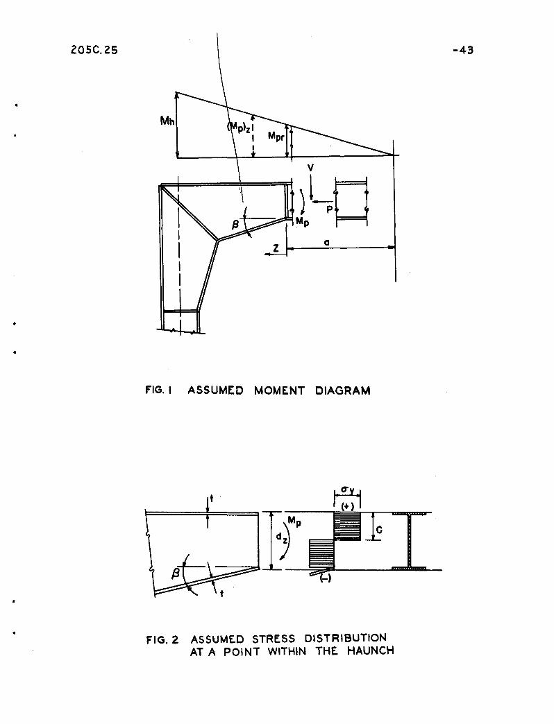
point and the haunch point is assumedoFigure 1
indicates a typical tapered haunched connection and
the assumed moment relationshipo
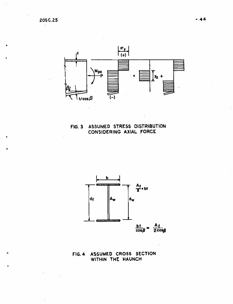
Figure 2 shows the assumed stress distribution at any
section within the haunch, with the influence of axial force
and shear neglectedoConsidering the condition of equilibrium
of stresses in the horizontal direction (Eqo 1) the distance
.'~: "
205C.25 ':"6
c from the top extreme fiber to the neutral axis is found to be
d zc =2
bt2w (l-cosj3) ( 3 )
whered z = depth of the h~unch at section z
b = width of haunch flanget = thickness of haunch flangew = thickness of haunch web
;.3 angle of sloping' flange
With the neutral axis given by-Eq. 3, the, magnitude of
the full plastic moment can be obtained fromEq. 2. However,
is defined as the plastic modulus z.
This takes the
The exp~ession
Eq. 3 shows the section is not symmetric. Consequently the
equation for the moment ~YdA would result in an unyieldly ex
pression. However, if the thiciness of the sloping flange is
multiplied by the factor,--l--, the neutral axis would becosj3
located at ~z _Eq. 2 then becomesd
~P ~ 2 0;f ydA
2 [f ydAo
value of
where tis the thickness of the top flange. The thickness of
the bottom flange is taken as t/cosl3 • The value of Mp is
then expressed':as
(6)
205c.25 =7
It is obvious that t~e above results are very similar to
those obtained for members having parallel flangeso For any
required value of the: plastic modulus, a thickness of flange
t can be obtainedo It is then only necessary to increase
the thickness of the sloping flange by the factor l/cos(3o
For small values (3, there is only a small difference in the
thickness of the flanges. However, for larger values there
will be a marked influence noticedo
2 0 2 Influence of Axial Thrust
Since portions of haunched connections adjacent to and
extensions of the column may be under the influence of axial
load, it is necessary to consider the reducti?n of the pla~tic
moment due to the axial load at full plastification of the
cross sectiono
In the stress distribution shown in Figo 3, there is
yield stress over the full cross=sectiono If the axial thrust
is assumed to be carried by a small area of web Aa located
near the centroid of the section, it is quite simple to compute"~
the-- magni tude of this area as:
where Ya is the depth
= L = WYacry
of web defining this area. It is
necessary to subtract from the theoretical plastic moment~com
puted from Eq. 6, the bending resistance of the web area
carrying the axial force. This resistance is taken as
(8)
j ,
205c.25
wherez =---
a 4
Hence, the modified plastic moment ~c is
=8
0,
This can be readily computed from the axial forces present
in the frame.
In order to estimate the magnitude of the effect of
neglecting the axial load, interaction relationships are
studied by assuming first a general cross section as shown
in Fig. 4.
Assuming the stress distri~ution shown in Fig. 3, the
magnitude of the axial force may be computed from Eq. (I)
p ; [ crydA ; cry wy.
However, since Py = cry (Aw) + cry (Af/2) + cry cos~ , (Af/2cos~)
= cry (Aw + Af )
Then:
where
P = WYa = Ya(10)
~ + Af }Aw+Af dw(lX;
Aw = area of the web
Af = area of both flanges
dw = depth of web
The assumed stress distribution of Figo 3 and Eqo:2
-9
..may be used to give
Mpc = 2 -.f~ ,, Ya.
2
cry ydA
W'Y 2 ]= a '4 I,.
where df = distance between centroids of the flanges e
However~ the plastic ~omentlneglectingaxial forc~ is~
1 ' 1Mp = cry ( 2 Afdf "4 Awdw)
-,
Hence~
= 1 =
2W'Ya
(II)
Solving Eqo 10 for Ya and substituting in Eqo IIp the
following expression is obtained~
(12)
A similar interaction equation can be obtained for the
case of the neutral axis in the flange p as
•
d ~'2 aw Af =" A -d f Aw1 + (1 +; dW) ~
w"
[p (1 + Af)Py A;
-10
It was stated in Reference 1 that for most rolled wide~
flange sections, the average values of dF/dw can be assumed as
It is believed that these same assumptions can be applied to
the built=up section of the haunch o Little error results
since the increase in depth and thickness of flange required
will be somewhat proportional .. These values can be substituted
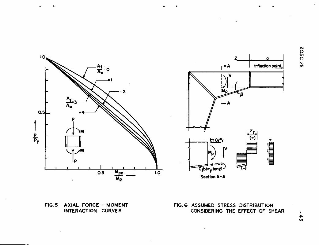
in Eqso 12 and 13 and curves may be plotted as shown in Figo 50
These are the identical interaction curves presented in
Reference 1 for members having parallel flangeso Therefore,
the problem of axial force can be handled in the same manner
for haunched connections as it is for rolled sectionso For
cases where the axial force P is less than 0015 Py the effect
of axial force can be neglectedo For values of P greater than
0015 Py the interaction curves of Figo 5 can be used with the
appropriate value of the ratio of flange area to web area o
If the haunch web thickness is maintained the same as
the adjacent rolled section, then obviously the effect of
the axial force on the haunch will not be as critical as its
effect on the adjacent rolled sectiono
2 0 3 Influence of Shear
Since more web area is available in haunched connections,
the magnitude of the shearing stresses within the haunch will
be less than those in the rolled sectiono However p the force
in the sloping flange influences the magnitude of the shear
force, and it is desirable to examine the influence of the
sloping flange upon the shear, and then to determine the
effect of the resulting shearing stresses upon the plastic
moment 0
The following a.asumptions will be made:.:
1) Normal yield stresses will be reduced due to the
effect of shear aE in the stress distribution shown,
in Figo 60
2) Miaes yield condition applies (Reference 16)
3) The web car~ies the ~hearing force
From assl~ption (1) the plastic moment will be
Mp =. ClOy' Z
where Cl is a reduction coefficient due to the ~h~~ring
stresseso
The resultant shearing force becomes
VR = V = Cl cry bt tan ~
Hence, the shearing stress ~. from assumption (3) becomesg
1: = V=bt·Clcry·tan~
dz w
for ~ inEqo (14) gives2
(V - bt ClOY tan ~)
expression obtained3
+ d 2 2Z W
20.5C.2.5 -12
Noting that V is approximately equal to MP/(a + z) where
(a + z) is the distance from the section in question to the
assumed inflection point, then
~( a+z
Substituting for Mp ,
3
Solving for the constant "Cl"
- bt tan (3)2
C 2 =11
1 + ""3 _
d2w2(~z a+z
Hence~
d 2Z
=1
1 + ""'3~-------'zw2 (--- - bt tan (3)2a+z
(1.5)
From Eq. 1.5 it can be seen that when (3 = 0, the expression is
the,same as for a beam withpar'alle1 franges. It is common
practice to ignore the infiuenc'e of shear on the bending
strength of beams. The term 3 (a~z)~ is in most casesd 2w2z
very small in magnitude.
"1
- bt tan (3)2 becomes even smaller than that
Hence, it 9an be
angle (3 is 'increased in tapered connections, Ithe
Z( a+z
As the
3term d 2 2
Z wobtained for a beam with parallel flanges.
, ' .
seen that the influence of shear is even of less consequence,'
in tapered connections than it is in prismatic sections.
205c.25 -13
..
Thus, within the tapered portion of the knee» it can be con=
cluded that the influence of shear on the maximum bending
strength can be neglected.
2.4 Location of Critical Section in the Haunch
The slope of the flange causes a continuous change in the
plastic modulus along the haunch. Hence, the location of the
most critical section is also variable along the haunch. As
ari assumption of the most critical loading on a haunched knee,
a linear moment will be assumed between the haunch and inflec=
tion point, as shown in Fig. 1
First, the moment at any point is equated to the plastic
moment .•M
Pr(a+z) = a Za y
0yZr (1 + ~) = 0y [bt (d=t + z ta.n (3)
+ ~ (d=2t + Z tan(3)2]
The equation is then solved for t.
d + z tan~ - ~(d+Z tan~) 2 'b~Z' (~::) (1 + ~)t =-------------------....-....-......&.-------2
Therefore, since
d - ~d2 (~ ) ~ 4 ~2
(16)
(17 )
Then: V(l z b 4Zr zz (1 + -a)1 + d tanf3 - + d tan(3)2 b=w d2 (b=w)t =t r
r~ 4Zrd2 (b=w) (l8)
205C 0 25
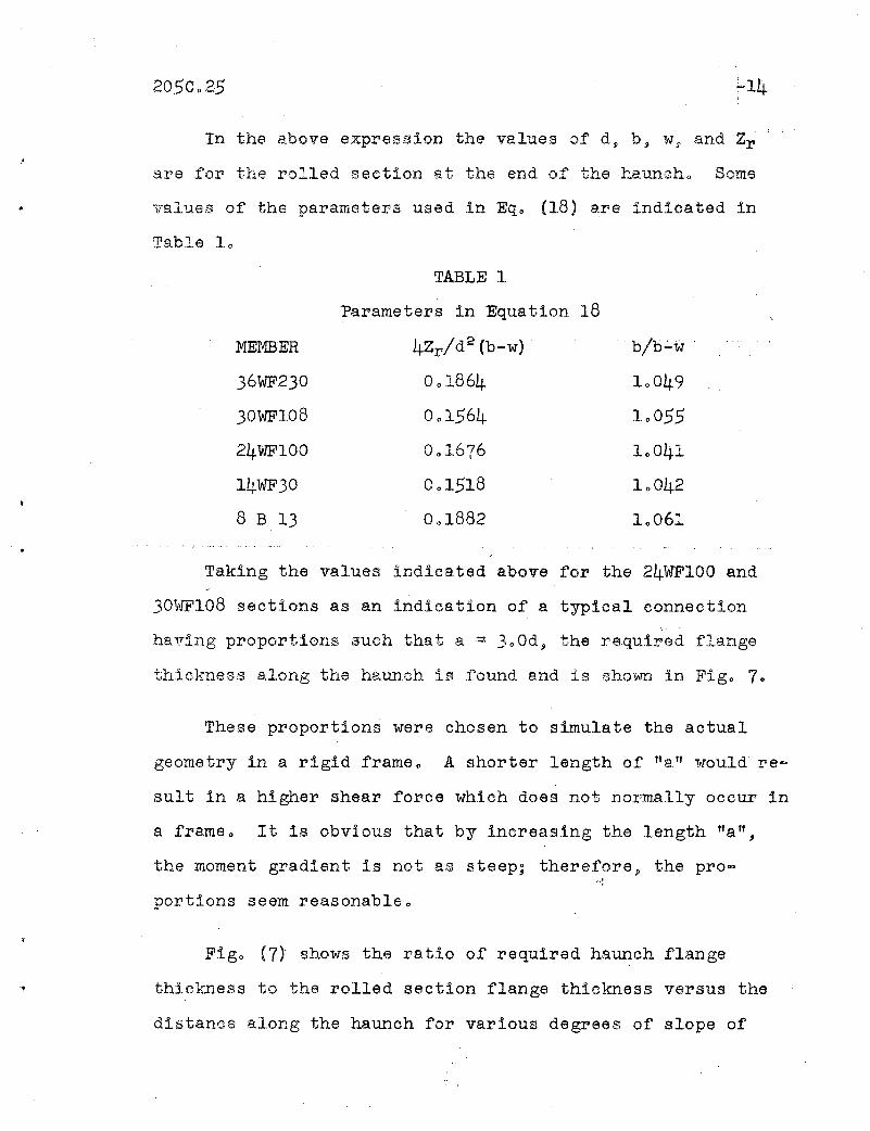
In the above expression the values of d~ b $I vT p and Zr
are for the rolled section at the end of the hauncho Some
values of the parameters used in Eqo (18) are indicated in
Table 10
- .
MEMBER
36WF230
30WF108
24WF100
14WF30
8 B 13
TABLE 1
Parameters in Equation 18
4Zr/d2 (b~w)
001864
001564
001676
001518
0 0 1882
b/b~w
10049
10055
10041
10042
10061
•
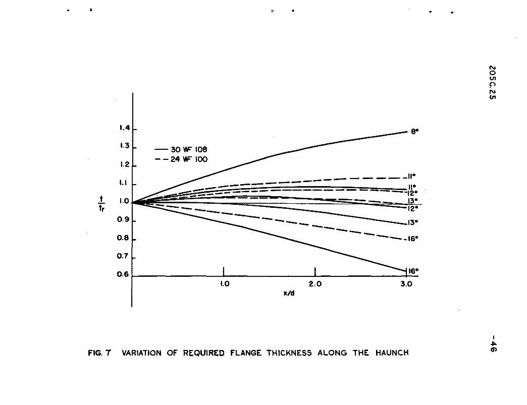
Taking the values indicated above for the 24WFIOO and
30~WI08 sections as an indication of a typical connection
having proportions such that GJ. =300d~ the required flange
thickness along the haunch is found and is shown in Figo 70
These proportions were chosen to simulate the actual
geometry in a rigid frameo A shorter length of !fall would re~
suIt in a higher shear force which does not normally occur in
a frame o It is obvi.ous that by increasing the length lIa ll,
the moment gradient is not as steep; therefore~ the pro-~.:
portions seem reasonableo
Figo (7) shows the ratio of required haunch flange
thickness to the rolled section flange thickness versus the
distance along the haunch for various degrees of slope of
-15
the compression flangeo _It indicates that for values of ~
less than approximately 12 dego, the greatest increase in
required haunch flange thickness is at the intersection of the
sloping flangeso Hence, the most critical section within the
haunch is located at that pointo When ~ is approximately
12 dego the increase in requiJI'ed flange thickness is n~arly
uniform along the hauncho When ~ exceeds about 12 dego -the
haunch flange r'equirement is 'always less than at its two ends 0
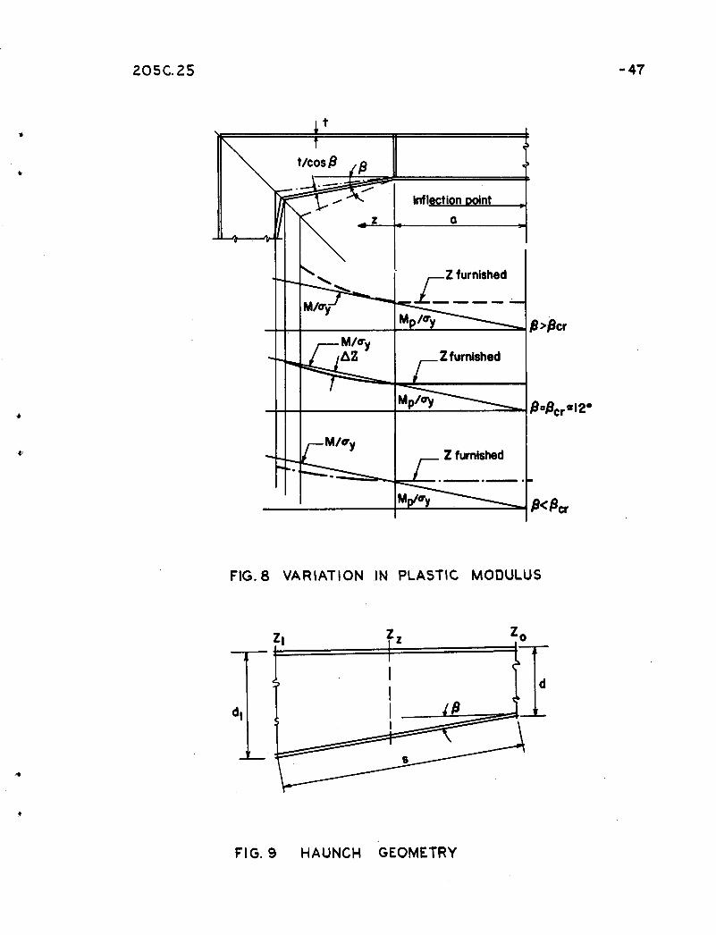
As another means of illustrating the effect of increasing
the angle between the flanges, a plot of furnished plastic
modulus vS o MVcry will be made along the haunch of a typ1cal
connection for various values of ~o The effective thickness
af the flanges within the haunch will be maintained the same
as those of the adjacent rolled sectiono To accomplish this
the sloping flange will be increased by the factor l/cos ~o
Figure 8 indicates that the critical angle of the sloping
flange is approximately 12 degoAt this slope the haunch will
_b~l;m~!o:r~ly _at _the ,plastic" condi ti0:t:o. When the angle ~ isr • ': 1', \ , ' . .., , ' I ': : '~' ':'..: .• ~
>-
less than 12 de go the full plastic condition will only occur
at the haunch intersectiono When ~ is greater than 12 dego,
the plastic hinge forms only at the intersection of beam and
haunch 0
205C 0 25'.
~' ......~.J'
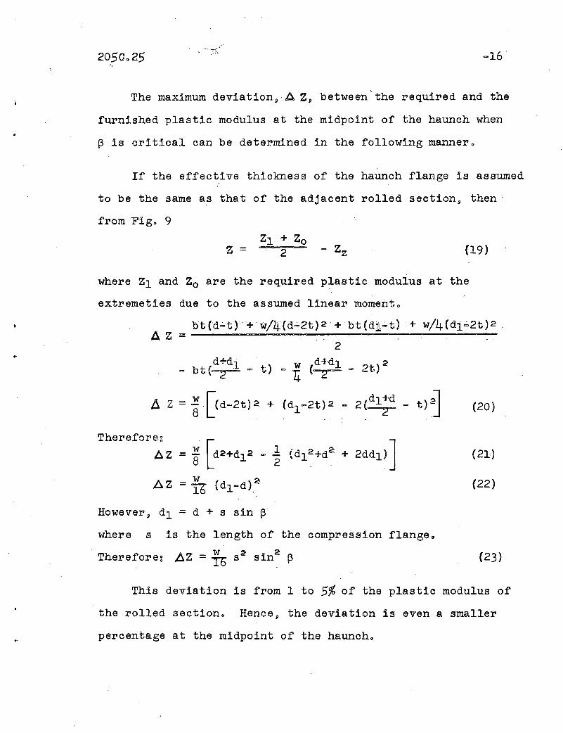
The maximum deviationpA Z» between'the required and the
furnished plastic modulus at the midpoint of the haunch when
~ is critical can be determined in the following manner o
If the effective thickness of the haUnch flange is assumed
to be the same as that of the adjacent rolled section» then'
from Figo 9
(19)
where Zl and Zo are the required plastic modulus at the
extremeties due to the assumed linear momento
bt(d.;.t)+w/4(d';'2t)2+bt(di.;.t)· + w/4(dl';'2t)2.A Z = --------------------
2d+d1 ' w d+dl 2
= bt (2 = t) ~; 4: (~ = 2t)
Ii Z = ~.[(d=2t)2 + (dl =2t)2 - 2(~ = t)J (20)8 J
Therefore:_ w [ 1A Z - - d2 +d12 - -8 2
AZ = 16 (dl-d),2
(21)
(22)
However, dl = d + s sin ~
where s is the length of the compression flangeo
Therefore: ,AZ = R S2 sin2 ~ (23)
This deviation is from 1 to 5% of the plastic modulus of
the rolled sectiono Hence» the deviation is even a smaller
percentage at the midpoint of the haunch 0
',I
2050025 ~17
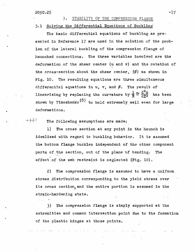
3. STABILITY OF THE COMPRESSION FLANGE
Solving the Differential Equations of Buckling
The basic differential equations of buckling as pre~
sented in Reference 17 are used in the solution of the prob-
lem of, the lateral buckling of the compression flange of
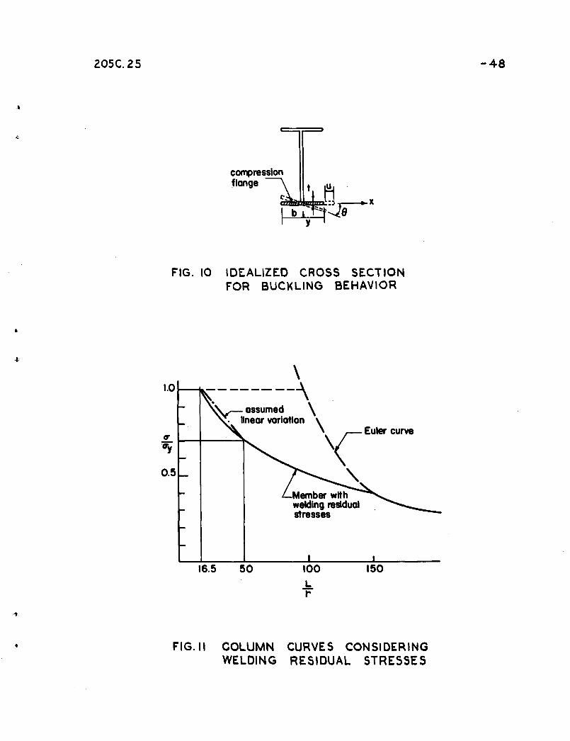
haunched connectionso The three variables involved are the
deformation of the shear center (u and v) and the rotation of
the cross~section about the shear center~ (¢) as shown in
Figo 10 0 The resulting equations are three simultaneous
differential equations in u~ v~ and ¢o The result of, 1 "v d2 u
linearizing by replacing the curvature by R =dZ2 has been
shown by Timoshenko(8) to hold extremelywe+l even for large
deformations 0
The following assumptions are made~
"
1) The cross section at any point in the haunch is
idealized .with regard to buckling behavioro It is assumed
the bottom flange buckles independent of the other component
parts of.the section, out of the plane ~f bendingo The.•...
effect of the web restraint is neglected (Figo 10}0
2) The compression flange is assumed to have a uniform
stress .distribution corresponding to the yield stress over
its cross gection~and the entire portion is assumed in the
strain~hardening state o
3) The compression flan.ge is simply supported at the
extremities and common intersection point due to the formation
of the plastic hinges at those points o

205C025 -18
4) The shear center coincides with the centroid due to
symmetry of the flangeo (xo = Yo = 0)
5) The warping rigidity is equal to zer?\(Elw =~)
6) Buckling in the plane of pending is preventedo
From assumption (6), the variable v is independent of the
other two, and the remaining two equations to be solved are:
d2 u P (u + ¢Yo) = 0, (24)'"(f2 + Erz y
~-~ Pro2 )
d dvElw
(GKT - + P~ Yo - a: x = 0 (25)dz dz dz z 0
where
These two equations are further simplified by using
as sumptions (4) and (5) (Elw = Xo = Yo = 0) 0
2 Pd u + = 0d 2 my U
z
E1 (GKT - Pr 2) = 0dz
0
(26)
(27 )
Note that Eqo (26) and Eqo (27) are independent.
Eqo (26), which represents Euler column buckling of the
compression flange, yields the following solution for the
aSsumed boundary conditions:
'.
22 11 E(sir) =-y (J
(28)
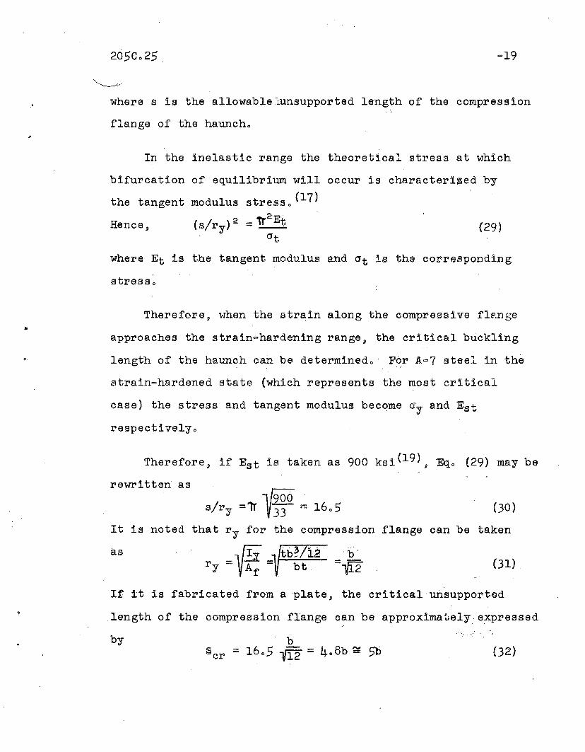
=19
where s is the allowable-Lunsupported length of the compression
flange of the hauncho
In the inelastic range the theoretical stress at which
bifurcation of equilibrium will occur is characterl~ed by
the tangent modulus atresso (17)
Hence, (airy) 2_ 'Tr2Et
(29)-crt
where Et is the tangent modulus and at ia the corresponding
stresso
Therefore, when the strain along the compressive fl~nge
Therefore, if Est is taken as 900 ksi(19), Eqo (29) may be
rewritten as
It is noted
as
Y900airy =11' 33 ~ 1605
that r y for the compression
r y =~f; =tb~(i2· =~2
(30)
flange can be taken
(31)
It it is fabricated from a plate, the critical unsupported
length of the compression flange can be approximately expressed
by(32)
-20
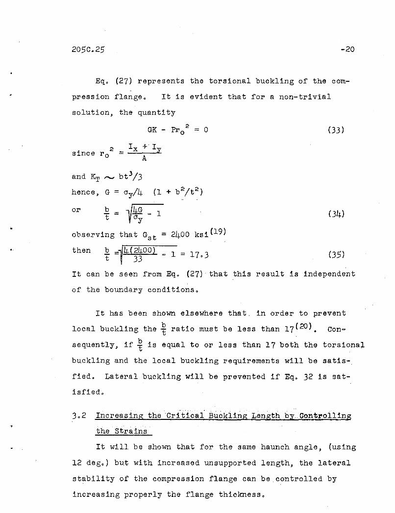
Eqo (27) represents the torsional buckling of the com-
pression flangeo It is evident that for a non~trivial
solution, the quantity
2since r o ==
2GK - Pro = 0
I +'Ix yA
(33)
(4)
,t
and Krr ,...., bt3/3
hence, G = cry/4 (1 + b 2/t2)
or b == 1M _1T cry
observing that Gst = 2400 ksi(19)
then b =1/4(2400) _ 1 = 1703 (35)t , 33
It can be seen from Eqo (27) that this result is independent
of the boundary conditions o
It has been shown elsewhere that. in order to prevent
local buckling the ~ ratio must be less than l7(20}. Con
sequently, if ~ is equal to or ,less than 17 both the torsional
buckling and the local buckling requirements will be satis-
fied. Lateral buckling will be prevented if Eq. 32 is sat
isfiedo
,.' ..
Increasing the 'Critical Buckling Length by.. Gontl'olling
the 'strains'
It will be shown that for the same haunch angle, (using
12 deg o ) but with increased unsupported length, the lateral
stability of the compression flange can be controlled by
increasing properly the flange thickness.
205C.25 -21
From Eqo 30 the cr±tical slenderness ratio of the un=
supported compression flange is given by
§. = 1605r
However» in many cases the geometry and the loading condi
tions may require a large haunch length such that
! = 50r
(36)
In order to prevent buckling at this slenderness ratio» it is
necessary to reduce the nominal stress in the flange 0 Since
it has been stated earlier that the compression flange is
treated as a colunL~» the !'elatlonshlp between stre~a and slender-. -
ness ratio ahou,ld be similar to that of a column 0 The relation-
ship is given in Figo 11» ~nd it is seen that the nominal stress
in the. flange corz1esponding to the slenderness ratio ofEqo (36)
must not be gr,eater than 0070 cry» or
crc = 0070 cry
If it is assumed that yielding is only oaused by bending» the
corresponding moment expression may be approximated by
(37)
where ~p is the pl~stlc ~QIllent of a cross section within the
haunch.
PAs the flange area increases» T decreaseso Thereforey
it is assumed that\
~ <" 0010l:y

205C025 -22
Thus to control the stress at 007 ~y the. moment capacity
must be limited to correspond to a fiber stress of 006 ~.
Thus M = 0~60 Mp or
. (}8)
(39)
•
•
This indicates that the required plastic modulus in the haunch
must be increased by 67% to accomplish..§. = 50.r
If the same web area is maintained and it is assumed that
the ratio df ~ 1003, the increased flange area Af can be simplydw
calculated
where Af and Aware the original areas of the flange and of the
web respectively. The' ~f ratio obtained fora'haunch pro-w
portioned by plastic analysis will vary between 0;75 and 1.0;
therefore s it is assumed that Af = 0.75 is the critical rati.o.,Aw
Thus, fromEqo 39,
is obtained.
(40 )
If it assumed that the relationship in Fig. 11 is linear
between'..§. = 16.5 and..§. = 50, the required flange thickness forr r
a haunched connection which has a slenderness ratio between
these limits can be calculated by interpolation.
16.5 (or ~ = 4/8), then A t equal zeto, and when
50 (or .~ ~ 14.8)then~t equals 1.1. Therefore
1.1 =k(14.8 4.8)and
k = 0.11
When'; equals
s- equalsr
205C.25 -2}
sHence, for a given b the percent increase in,t required. is
A t = 0.11 (~ - 4.$)b
(41 )
The required thickness of the tension, and compression flange
is then(1 + .6t)cos 13 (42 )
'1
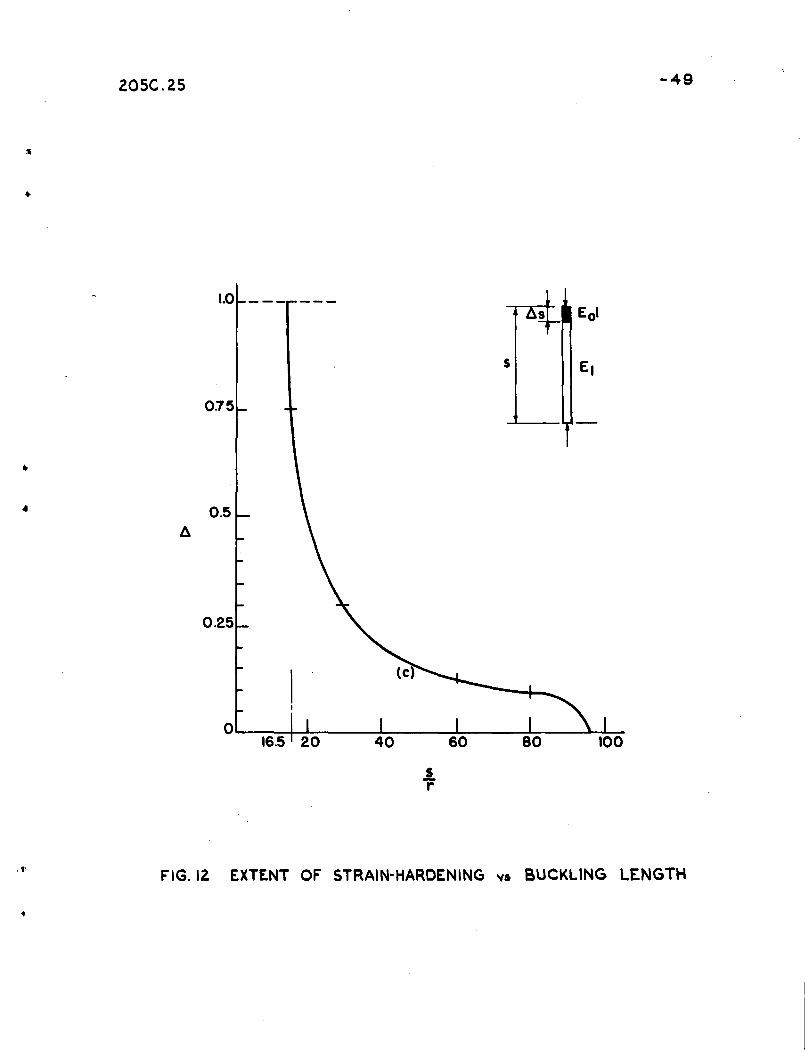
3.3 Increasing the Critical Buckling Lengh by Decreasingthe Haunch Angle
When the angle·1S is greater than 12 dego, the compression
flange of the haunch willLno longer be uniformly strain
hardened as shown in Fig. 8. Full plasticity of the cross
section1that is, strain ha.rdening, Vlrill commence from that
end of the haunch joining the rolled section,thus elastic and
strain-hardened material will be present in the 0auncho ' The
problem of an axially-compressed column with variable bending
stiffness has been solved(18), and the relationship between
,the extent of strain-hardening and the critical buckling length .
is shown in Fig. 12.
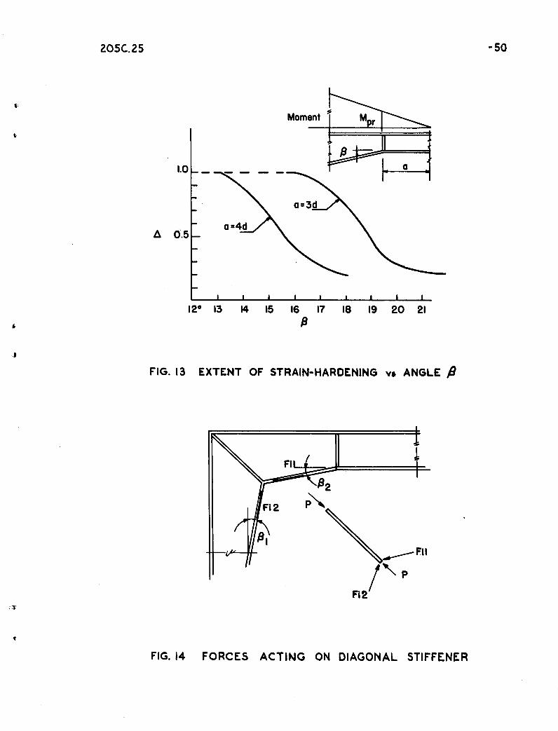
In this analysis of haunched connections it is assumed
that the strain-hardened, zone A s extends from the rolleq.
section to the point where the exter~al moment is equal toi
-r the" yield, moment furnished by the section. Therefore, the;
extent of yielding depends on two variables, the moment gradient
and the angle.& which determines, Z at any point in the haunch,.
, If the yield moment of the section at a distance z is equated

;
•
·205C.25
to tqe a~pliecl moment and it is assumed that d = 2b, the
curvesl, shown in Fig. 13 will result. These curves indicate'.1 I
that ~ ,'for various moment gradients, a very small increase in If;
.iwill decrease the length of the strain-hardened zone consider=
ably. Fig. 13 shows that such a decrease in LlS will ~ermit
an increase in the allowable slenderness ratio.
It is to be noted that the curves in Fig. 13 are based
on p>articularly sele:;ted dimensions" For any gi -\;Ten haunch
simi.lar curves can be obtained by equating the a.pplied moment
to the yield moment of a section z distance away from the
juncture of the haunch and the rolled section.
3.4 Reinforcement in the Knee__"""SI"_.._.;,......: ~._~-.._.-..- '
There are several requirements that are iIJ;lposed on, a :.knee
by the applied forces and mot~nts. These requirements are~
1) The knee must resist the unbalance of the inside
flange forces.
2) The knee must resist any serious shear deformation.
3) The bit ratio of any axially loaded components must
be less than 17 in order that local buckling will
not occur.(20)
The plate joining, the point of intersection of the two
outside flanges of the haunch with that of the two inside
flanges is referred to as a diagonal stiffener. The method
of' analysis that follows is, an approximate means .of determining
..
205C.25 -25
its required area. The assumptions made in the development
of the method, are~
·1) The compression flanges.transmit a flange force of
magnitude = O-y,Afo (This is true for haunches
whose angle 11<12 deg. and a very close approxi
mation for angles larger than 12 deg.).
2) :'.The component of. the flange force passing through
the rentersection of the two outside flanges and the
two inside flanges must be resisted by a diagonal
stiffener and a strip of web of the same width as
the stiffener thickness.
The assumptions made are probably somewhat severe •
. However,. in a!.'previously tested connection (13) the diagonal
stiffener was observed to yield 9 even though thicker than re-
quired, when proportioned by the method presented in Ref
erence 2. Consequently, it seemed desirable to attempt
another method of proportioning the knee reinforcement •
. In a haunched connection,as shown in Fig. :.14, where the
girder intersects·:,the column at right angles j the resulting
force P, acting on the diagonal stiffener is
P = Fi 1 sin (45 0 -192) + Fi 2 sin '( 45 0 - p\ ) (43 )
However, Fi equals o-yAfiand for the case of symmetry where
)91 equals~2 Eq. (43) yields
,p
205C.25 -26
(46 )
•
The re~uired stiffener area is then
As = E-- = 2 Afi sin.(45°-(31)aySince the width of the.' stiffener is maintained equal to the
flange width, therequ~~ed~hicknessis
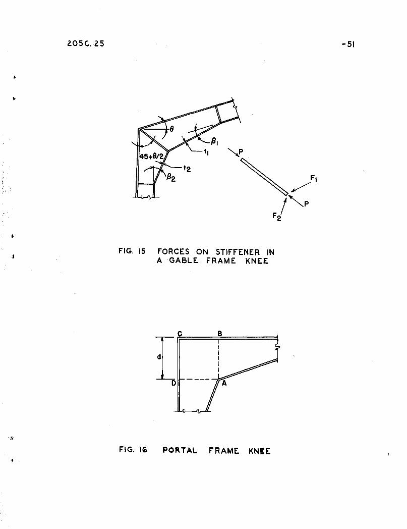
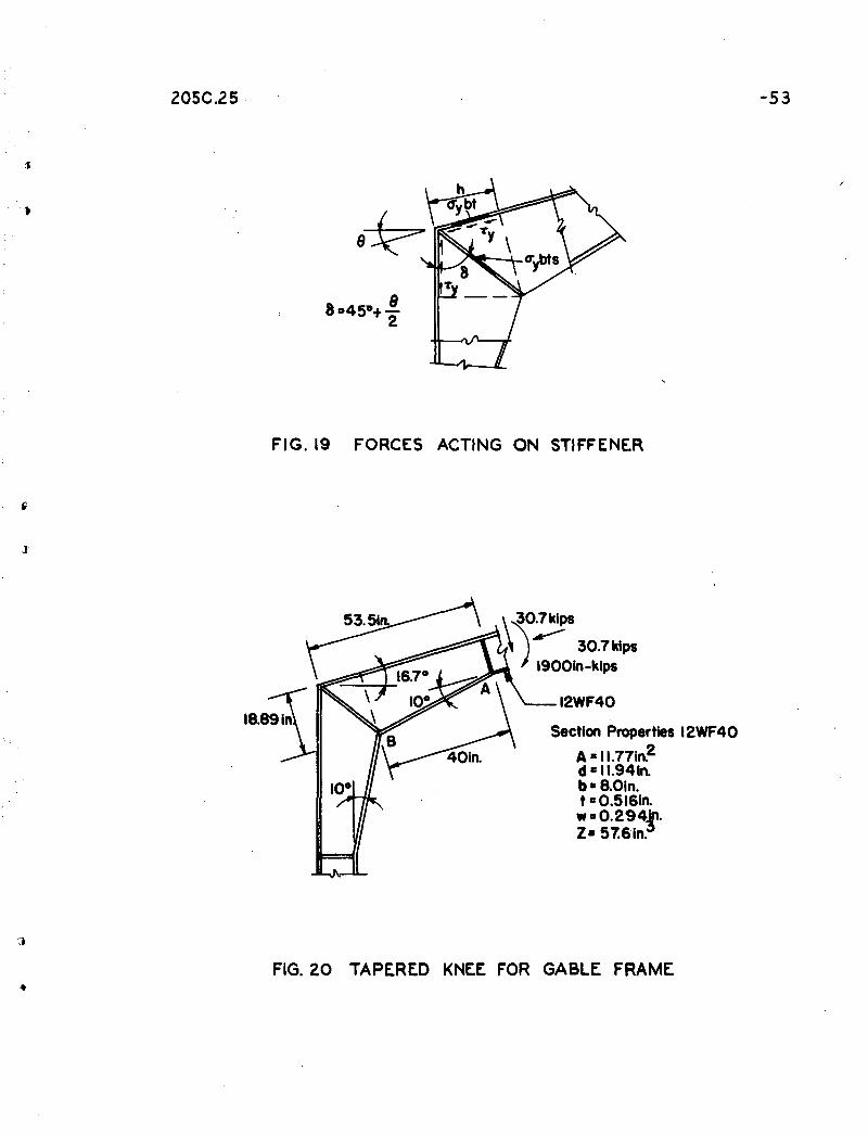
where t c is the thickness of the compression flange •. For gabled
connections where the rafter intersects the column at an angle
greater than 90°, similar reasoning leads to the expression
.' ( /J G) . ( 45 °- 1.2 1· - Q2)'t s = tl sin 45 °-/:;12:- 2 + t2 Sln {-.J
where the nomenclature is as given in Fig. 150'
. Similarly, the·stiffeners·at the limits of the knee may
be designed to take the unbalance of the flange force due to
the sudden'change in direction. Again, the flange force can\
be considered as the yield strength of the flange. Hence, the
required stiffener area is
As = Af Sin/J
If the stiffeners are all made the same width as the 'flange,
the re~uired stiffener thickness is
t s = t·. sin (J (48)
To prevent the possibility of web buckling and the presence
of high shear stresses:-:in the web, the web thickness should be
made at least as thick as that of the adjoining rolled sections.
In order that the·knee may be able to resist serioUis'shear
deformation, the re~uired thickness of web within'thehaunch
205C.25 -27
"
'f
is analyzed. Fig. 16 shows a typical corner connection in
'which the following assumptions ,are made for simplification.
1) The bending moment at the section, AB results in the
full plastic flange force in the flanges.
2) The shear force V is resisted by the web and the
vertical component of the force in the sloping flange.
,3) The normal force P is'neglecteo..
4) Stress concentrations are not considered.
5) Restraint due to bending of individual flange ele-
ments is neglected.
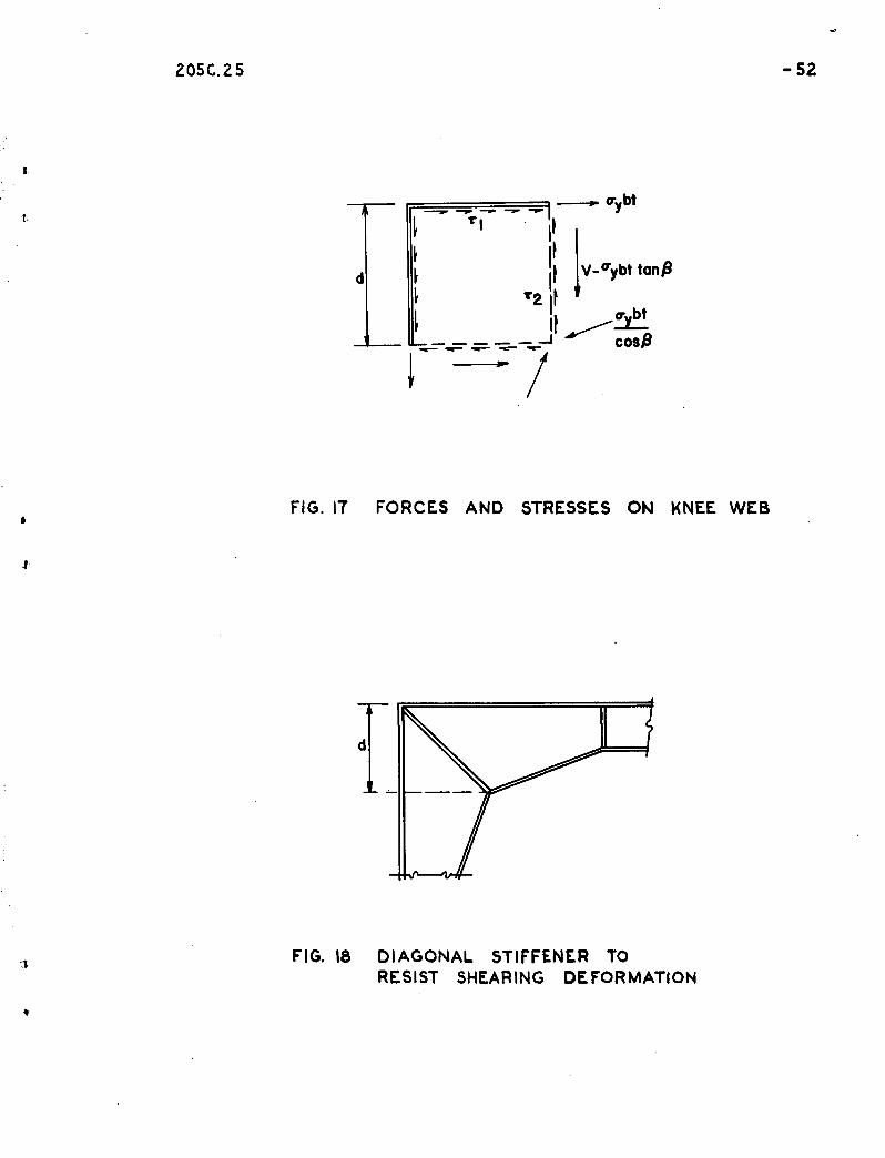
Taking into account the above assumptions, the forces and
stresses are applied to the knee as shown in Fig. 17.
Considering first the problem of a symmetric knee and com
puting the shear stresses ~ on the web panel.
<Tybt'tlwd
_ <T"ybt"t' 2 - wd
( V _<rybt tan...8) _ aybt, sinJ3wd wd ~
(49 )
=o-y bt-Vwd
(50)
However, 7"1 is always greater than 72, and increases
in magnitude as~ increases. It is important in connections
that yielding due to shear forces does not occur in the un
stiffened web of the knee, si:nce' yielding can cause large
shearing deformation. This deformation will be assumed to
occur under the ,action of pure shear of the magnitude '~l'
.205C.25 -·-2$
which will be conservative. Ado~ting the Mises yielding
condition, the web will yield when the maxi~um shear stress
is~-~lIy "0
Substituting into Eq. (49) the
{Ibtw =r d
(51)
required web thickness is
(52)
When dissimilar rol!ed shapes are used such that symmetry
is not evident in the knee, the most critical section must be
"analyzed.
If the haunch is foun~ to be deficient in web thickness
whenEq. (52) is applied, the extra web thickness required
can be obtained with doubler plates, or by providing a diag
onal stiffener. The required diagonal stiffener area may be
"For portal frame knees as indicated in~Fig. 1$ the re-
quired stiffener area is:
Therefore, tsb =
wd bt sAf = - +iT ff
{2 (btt
_..wd:.). .yj
Hence, the stiffener thickness becomes
t s = (tt _ wd; .. ) ff ( 53)Vb "
where tt = thickness of the tens~on flange,"" and ·d is the
minimum depth at the haunch intersection.
.'
205C.25
A·similar approachaflfllied to haunched, knees used in
gabled frames ~eads to the expression
= Dbt:·wr h
for the re~uired web thicknesi and
""-29
~ . 2wht= 2t coso' -~sf3b
2ccos 0
sinO
..
"
for the diagonal stiffener thickness when the web thickness
. is inade~uate; hand J are as indicated in Fig. 19 •
.'
205C.25 -30
4. DESIGN RECOMMENDATION·AND DESIGN·EXAMPLE
4.1 'r Recommended Design Procedure··1 '"-
Initially, the moments and forces present in a rigid
frame should. be determined by one of the plastic methods of
1 .ana-,-ysls . The .angle,/t.be.,twsen.:::tb..EL.:strai.ght,.ar:td._.$lo.ping,-...flanges
..
..
. should be selected. The haunched connection can then. be
designed in the following manner:
.1) Select the general proportions of the connection
i.e., the dista~ce b~tween the outside corner and the inter-
section of haunch with rolled section.
2) Obtain from plastic design the size of rol~ed section
required at the intersection point. For ease in fabtication
the flange width and web thickness of the haunch is made
approximately equal to that of the adjacent rolled section •
. 3) . Next, determine the maximum allowable unsupported
length of the compression flange between. points of lateral
support by scr = 5b. If this is exceeded, the angle,# or 'the
general. proportions of the haunch can be adjusted to fall
within this-limit. As a more general expression, the critical
unsupported length can be expressed as scr = 16.5 r xx ' where
r xx is the·radius Of gyra:tion of the flange plate'with respect
its plane.
4) A minimum value of t can be obtained since the bit
ratio cannot exceed 17.
5) If the anglet9 is equal to or less than 12 deg., the
required. plastic modulus at the common intersection point of
the slopin~ flange can be obtained by the exp~ession
205 C:•.25 -3:1
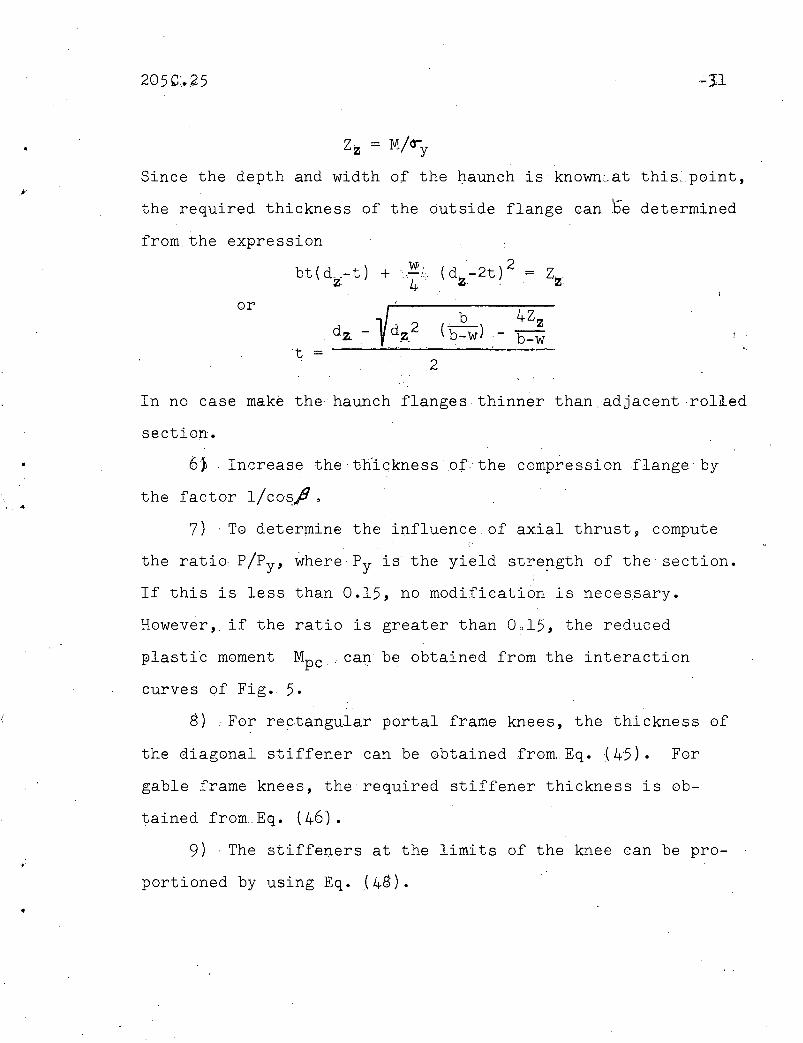
Zz = M/&-y
Since the depth and width of the l).aunch is known:-at this:_point,
the required thickness of the outside flange can be determined
from. the expression
bt(d.-t) +z-Wi,
. ,..-/.',
4
. 2(d_-2t) = Z.z - z-
or
t =dz - Ydz2 . (~) - ~
2
,.
..
•
In no case mak~ the haunch flanges thinner than.adjacentrolled
section.
oj Increase the·thicknessofthe compression flange-by
the factor l/cos.f1 •
7) . To determine the influence of axial thrust, compute
the ratio p/py , wherePy is the yield stre?gth of the section.
If this is less than O~15, no modification is neces~ary.
However,; if the ratio is greater than O?15, the reduced
plasti~ moment Mpc ; can be obtained from the interaction
curves of Fig. 5.
8) . For rectangular portal frame knees, the thickness of
the diagonal stiffener can be obtained from Eq. {45). For
gable frame knees, the required stiffener thickness is ob-
tained froffi.Eq. (461.
9) The stiffeners at the limits of the knee can be pro-
portioned by using Eq. (4g) .
205c.25 -32
•
t,
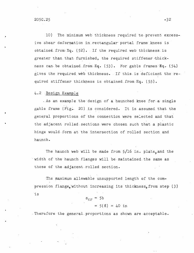
10) The minimum web thickness re~uirea to ~revent excess
i ve she'ar defermation in, rectangular ~ortal frame: knees is
obtainea,from: E~. (52). If the re~uired web thickness is
greater than that, furnishea, the re~uired stiffener :thick-
ness can, be obtainedfr0m:E~. (53). For gable frames Eq. (54)
gives the re~uired, web thickness •. If this· is deficient the re
quired stiffener thickness is obtained,fromEq. (55).
4.2 ,~esign Exam~le
-As an exam~le the design of a haunched knee for a single
gable frame (F:ig~ 20), is considered. It is assumed that the
general ~ro~ortions of the connection were selected and that
the adjacent rolled sections. were chosen such that a ~lastic
hinge would form at the intersection of rolled section and
haunch.
The haunch web will be made from 5/16 in. ~late3and the
width of the haunch flanges,will be maintained the same ·as
those of the .adjacent rolled section.
The maximum allowable unsu~Ported length of the com
pression flange,'without increasing its thickness~from step' (3)
isscr = 5b
= 5(8) = 40 in
Therefore the general proportions as shown· are acceptable.
205C.25 -33
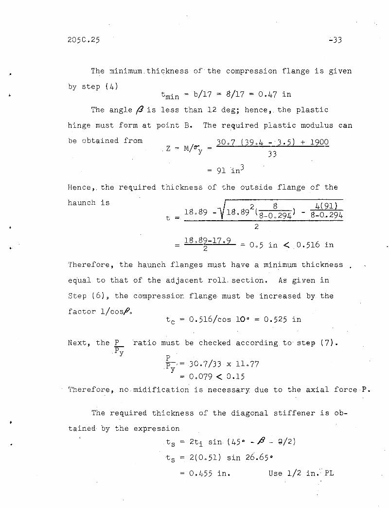
,. The minimum,thickness of the compression flange is given
.,by step (4)
b/17 = 8/17 = 0.47 in
The angle (J is less than 12 deg; hence" the plastic
hinge must form at point B. The required plastic modulus can
be obtained from z = M/~ = 30.7 (39.4 -3.5) +1900y 33
= 91 in3
Hence,. the required thickness of the outside flange of the
haunch is 2 8 4(9l}t = _18_._8_9_-~_1_8_08_9_(8_-_0_0.-.,;29_4;.-.}_'-____.8_-_0.......2_9_4
2
= in < 0.516 in
t c = 0.516/cos 10 0 = 0.525 in
Therefore, the haunch flanges must have a minimum thickness
e~ual to that of the adjacent roll. section. As given in
Step (6)~ the compression flange must be increased by the
factor l/cosft.
Next, the PPy
ratio must be checked according to step (7).
Pp-,=30.7/33 x 11.77'y
= 0.079 < 0.15
Therefore, no.midification is necessary due to the axial forceP.
The required thickness of the diagonal stiffener is ob
tained by the expression
,t s = 2ti sin (45 0- ft - G!2)
t s = 2(0.51) sin 26.65 0
0.455 in. Use 1/2 in." PL
205c.25 -34
= 0.506 ~ 0.312 in
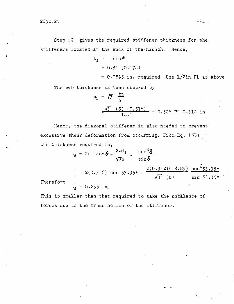
Step (9) gives the re~uired stiffener thickness for the
stiffeners located ..at the ends of the haunch. Hence,
t s = t sinfS
= 0.51 (0.174)
= 0.0885 in. required Use 1/2in.PL as above
The web thickness is then checked bybt
wr = f3h
If (8) (0.516)14.1
. Hence,_ the cliagonal stiffener js also needed to prevent
excessive shear deformation from occurr.ing. From:.Eq 0 (55)
t·the thickness required is,
2wdlt s = 2t cos8'-"'fJb
Thereforet s = 0.235 in.
This is smaller than that required to take the unbalance of
forces due to the truss action of the stiffener.
205C.25 -35
5. SUMMARY AND CONCLUSIONS
Several elastic methods of analysis are available' for
use in designing tapered haunched connections. However, the
plastic method of analysis presented herein will;'provide ,a
suitable method of proportioning haunched connections that is
much simpler than any known elastic solution. The solution
also takes into consideration the buckling characteristics of
the component parts of the connection ,as well, as the bending
strength.
This report is pri~arily a theoretical study of theprob-
lem. A series of tests was conducted on connections designed
,and proportioned by the procedures developed herein, ,and the
results showed good agreement. Several tests had been con
ducted in the past which may be correlated to a certain extent
with the results presented here. These connections were tested
in the plastic range and make it possible to examine several
of the problems that were studied in this report. The testsIi
are favorable in their correlation. ,The following summar'lzes
the results of this theoretical study of tapered hauncped
connections:
,1) .' It has been shown that haunched corner connections
with tapered flanges may be analyzed by the~lastic bending
theory. The steps for'proportioning tapered haunches are
given in Se£ti~n 4.1,
-36
2) 'Previous work has shown that failure ofa built-up
haunch has been, through lateral buckling of the compression
flange,even though ade~uatebendingstrengthi~ provided.
Plastic bending theory is based on theprece,pts of a structure $tabil
ized against-,buckli~g,•.,,,,,,,,,Theref,orei.,a.,rne.thQ~'.,b..a.s,,heen~..dev':eloped.for
assuring sufficient rotation capacity such that failure does
not prevent the haunch from transmitting the re~uiredplastic
hinge 'moment.
3) The influence of 'axial force on haunched connections
can, be considered in the same manner as for rolled sections.
Generally, the same modification that is applied to the adjacent
rolled sections can. be used.
4) Shear was found to have little if any influence on
the plastic moment of tape~ed knees.
5), The critical sections in a tapered knee are found to
be at the intersection of the taper and rolled sectionand,at
the intersection of the sloping flanges, when, the. angle () is
equal to or less than 12 deg.
6) When the angle between the sloping flanges is greater'
than 12 deg., the critical section is at ~he extr~mities of the
haunch.it.
7) The geometri~ conditions of the compression 'flange
must be such that b is less ~than or equal to 17 in order thatt
the haunched portion may developl'arge plastic deformations.
wi thout local buckling and a conseqlJ.ent reduc.tion in load. ,{ 20)
205C.25 -37
• 8) ,An,approximate method of determining the required
stiffening for tapered knees is given by Steps (8), (9), (10)
of Sec. ~.l.
9) A design example illustrates the applicati0n of
this plastic analysis.
•
.-
•
205C.25
6. _ACKNOWLEDGEMENT
This work was carried out at-Lehigh University in the
Fritz Engineering Laboratory. It is based on a thesis by
John W. Fisher which was submitted in ~artial requirement
for the degree of Master of Science in June 1958. The work
_was done as ~art of a program on Welded Continuous' Frames
and Their Components, s~onsored jointly by the Welding
Research Council and theU. S. Navy with funds supplied by
the American Institute of Steel Construction, the American
. Iron and Steel Institute, and the Bureau of Ships. Techni
cal guidance for this project is furnished by the Lehigh
Project Subcommittee of the Structural Steel Committee,
Welding Research Council. Dr. T. R. Higgins is Chairman
of the Lehigh- Project Subcommittee~. Dr. L. S. Beedle is
Director of the project.
The authors wish to thank Dr. Weldon Niva.and
Mr. Joseph Yurafor their assistance in producing this
report.
>',
•
205~.25 -39
7. NOMENCLATURE
A Area of cross-section
,Aa Area of web resisting axi~l force
Af =~. Area ~6f·· two flapges 6f WF shape', Af = 2bt
A~ Increased area of two-flanges of haunch
Aw Area of web between. flanges
a Distance0etween inflection point and haunch extremity
b Flange'width
ClReduction coefficient for normal stresses
c = Distance from neutral axis to extreme fiber
d = ~Depth of Section
dw Depth of web
d z
E
G
I
'. I w
=
=
=
=
=
=
=
=
=
Distance between. centroids of flanges
Depth of section at a point within the haunch
Yo'ung's modulus of elasticity
Tangent modulus
Strain-hardening modulus of elasticity
Modulus of elasticity, in shear
Modulus of elasticity in shear at the onset ofstrain-hardening
Moment of inertia
Warping constant
k Reduction coefficient
Kt = Torsion constant
Bending mGment
Plastic moment; subscript nrh indicates rolled. section
,205C.25 ·-40
Bending moment of area carrying axial force
Normal force.' r
Moment. at point z
Plastic hinge moment modified to include the effectof axial cempression
Axial force corresponding to yield stress level;. P =A cr'y
Radius of gyration
I x + I y 'Xo .+ Yo' + --::';~-:----'_I..-..
A
S ,I/C,Elastic section modulus
s 'Length of compression flange of haunch
'Mpc =•
Mwa =
Mz
P
P =y
r =
ro 2
I •
= Critical length for lateral buckling
s/r = Slenderness ratioI I
,t = Thickness of flange; subscripts c and t denotecompression andc tension
t s Thickness of stiffener
t' Increasea thickness of:haJnch flanges
u,v,w= Displacements in,x, y, ana z directiens
v =
Vr =
w =
x =
Shear force
Resultant shear force
Web thickness
Lateral coerdinate
xG'Yo= Coordinates of the shear center
Ya
Z
=
=
Depth of web on which the axial force acts
Plastic modulus;~ Z = Mp/c1y
Za ·Plastic moaulus of section.carrying,q.xial force
•
205C.25 .;,.41
Angle betw~en the inside and outside flanges withinthe·haunch
•
Q
Angle of rotation of ctoss-section about the shear center
Angle between vertical flange and diagonal stiffener of'a tapered knee in a gable frame
Angle of rise in gable frame
Yield stress level
- . Shear stress

•
•
•
•
205C.25
8. FIGURES
.;..42
•
•
20SC.25
FIG. I ASSUMED MOMENT DIAGRAM
-43
c
• FIG. 2 ASSUME.D STRESS DISTRIBUTIONAT A POINT WITHIN THE HAUNCH
205C.25
t
•
- 44
•
..
FIG. 3 ASSUMED STRESS DISTRIBUTIONCONSIDERING AXIAL rOReE
df Aw
~.btZ
.ll- _ ~coslJ 2cos~
•
FIG.4 ASSUMED CROSS SECTIONWITHIN THE HAUNCH
• .. •
No01{)r\JU1Z·-~r1'-:••-J
0.5
tP
rhM tTyP ~Py D btCI.~ T
:1~ !V'i:M
F-e;t,;tT;;::P0.5 1.0
Section A-A
FIG.5 AXIAL FORCE - MOMENTINTERACTION CURVES
FIG. (Q ASSUMED STRESS DISTRIBUTIONCONSIDERING THE EFFECT Of SHEAR I
~en
'. ..
---
8°.----------
--------------- __16°
_-----11°--~..-
_------- 11°~---- _-------------------12°....--- ---
-30W: 108--24 w: 100
1.4
1.3
1.2
1.1
i 1.0tr
0.9
0.8
0.7
0.61.0 2.0 3.0
xld
FIG. 7 VARIATION OF REQUIRED FLANGE THICKNESS ALONG THE HAUNCH
M/tTyf.Z
•
•
20se.25
t
z a
------4--E~-------=.... ~<~cr
FIG.8 VARIATION .IN PLASTIC MODULUS
FIG. 9 HAUNCH GEOMETRY
-47
205C.ZS -48
•
compressionflonge
t tJ__., ,-' • x
b. '~t~8y
FIG. 10 IDEALIZED CROSS SECTIONFOR BUCKLING BEHAVIOR
Member withwelding residualstresses
\1.0~._--------\
'~assumed \• linear variation \
\~EUI.C"'"
"16.5 50 100 150
LF
,.,
.~ FIG. II COLUMN CURVES CONSIDERINGWELDING RESIDUAL STRESSES
..
lQSC.25
1.0 --- ---
5
-49
•
0.75
0.5
O'--_-+-...&-__----L .L.-__--L-__~L.._
sr
FIG.12 EXTENT OF STRAIN-HARDENING '15 BUCKLING LENGTH
i'
,
.J
l05C.25
~
Moment
Q
12° 13 14 15 16 11 18 19 20 21IJ
FIG. 13 EXTENT OF STRAIN-HARDENING v. ANGLE P
FIG. 14 FORCES ACTING ON DIAGONAL STIFFENER
-50
I
lOSC,.25
","P .
FIG. 15 FORCES ON STIFFENER INA GABL~ FRAME KNEE
C B
d
o
FIG. 16 PORTAL F'RAME. KNEE
-51
•
lOSC.25
FIG. 11 FORCES AND STRESSES ON KNEE WEB
FIG. 18 DIAGONAL STIFFENER TORESIST SHEARING DEFORMATION
-52
:1
'.
..I'
•
20SC.25
FIG.19 FORCES ACTING ON STIFFENER
\.30~S
,,\\ 30.7 kipsI ) 1900in-kips
12WF40
Section Properties 12WF40
A =11.771n.2d =I 1.94In.b=a.Oln.t =0.5I6In.w=0.294r·Z·57.6In.
FIG. 2.0 TAPERED KNEE FOR GABLE FRAME
-53
205C~25 ~5.4
9. REFERENCES
1.'J
" .Beedle, L. S., Thurllmann, B., Ketter, R. L.PLASTIC DESIGN IN STRUCTBRALSTEEL,. 1955· Summer CourseLecture Notes, Lehigh Univers:ity"-AISC, 1955
2. Topracsoglou, A. A., Johnston,. B. G., Beedle, L. S.CONNECTIONS FOR WELDED CONTINUOUS PORTAL FRAMES s
.The Wel&ing Journal, 30(7), 30(S), and 31(11), 1951and 1952
3. Fisher" J. W., Driscoll, G. C.,Jr.,. Schutz,. F. W.,Jr.BEHAVIOR OF WELDED CGRNER C©NNECTIONS, .' The Welding
. Journal 37(5), R~search Supp 1., .216-s,May 1958
4•. Fisher, J.W."Driscoll, Go C.,Jr.,.Beedle, L. S.PLASTIC.ANALYSIS AND DESIGN OF SQUARE RIGID FRAMEKNEES, Welding' ResearhCouncil Bullo No •. 39, April1955
Osgood, W•. R.A THEORY OF, FLEXURE FOR BEAMS WITH NON ,,-PARALLELEXTREME FIBERS,. Journal of. Applied Mechanics, 6(3),ASME, 1939
Bleich,.F •. DESIGN OF RIGID FRAME KNEES,. American Institute of.Steel Construction, 1943
0 5.":.l
6.
7. Olander,. H. C.,A METHOD FOR CALCULATING STRESSES IN.' RIGID) FRAMECORNERS, Transactions ASCE Vol. 119, Pape~ ~698,1954
8. Grif.f.iths.J~ D•.SINGLE SPAN RIGID FRAMES· IN STEEL, American Instituteof. Steel Construction, 1948
9. Smith, J. E.BEHAVIOR OF TAPERED HAUNCHED CONNECTIONS,. Fritz Engineering Laborator~ReportNo. 205C.20,Lehigh University,July 1956
1
..
10. Stang, A•. H., Greenspan, M., Osgood, W.R.STRENGTH OF A RIVETED STEEL RIGIDFRAlVlE .HAVIN.G.iA.CURVEDINNERFLANGE,.R.P. 1161,.Journal of Research, p •. S.National Bureau of. Standards, Vol.21,. p 853, 1938
11. Lyse, I., Black, W. EoAN INVEST.IGATION OF STEEL RIGID FRAME KNEES, TransactionsASCE. Vol. 107, Paper 2130, 1942
205Co,25 -55
'.
•
12. Hendry, A. W•.AN INVESTIGATION OF THE STRESS,DISTRIBUTION,IN,STEELPORTAL FRAME KNEES,J0urnal 0f the Inst. Gf StructuralEngineers" Vel. 25 fl 101, 1947
13. Hendry,A. W.AN INVESTIGATI@N OF THE STRENGTH 0F WELDED P@RTAL FRAMECONNECTI©NS ," Jnl. Inst. of Structural Engineers z Vol. 28 ,
.. p. 265, 1950
14. Fisher, J., W., Lee, G. C." Driscoll, G. Co,Jr.BEHAVIOR OF HAUNCHED CORNER CONNECTIGNS, Fritz EngineeringLaborat0ry Reflort 205C.27" Lehigh University, 1961
15. Fisher, J. W., Lee, G. C., Driscoll, G. C., Jr •. PLASTIC \ANALYSIS OF CURVED HAUNCHED CONNECTI@NS,' Fritz
Eng.ineering- Laboratory Report 205C.26,.Lehigh University,1961 '
16. Prager, W., Hodge, P. G.THEORY OF PERFECTLY PLAS,TIC SOLIDS, John Wiley & SGns, Inc. ,1951
170 Bleich, .. F.BUCKLING STRENGTH OF METAL STRUCTURES,. McGraw-Hill BookCompany, New York, 1952
18. Timoshenko, S.THEORY OF ELASTIC STABILITY, McGraw-Hill Boek' C0.,
. New York, 1936
19. Haaijer, G•. PLATE BUCKLING IN THE STRAIN,..HARDENING. RANGE,:Trans,..action,ASCE. Vol. 124, 1959
20. Haaijer,' G., Thurlimann, B.ON INELASTIC BUCKLING IN STEEL, Journal 0f the'Engineering Mechanics Div." Proceedings ASCE. 84 (EM-2)Paper 1581, April 1958