Embed Size (px)
Citation preview

Welded Continuous Frames and Their Components
"'irI'l E'V.L·lIJUL'i'I1IOlf OF P~L~'lSTIC ",'lN~'~J~YSI:3 .L·;.S~'~FPr-JIF~I) TO STRUC':PUR.d.T-I DESIG·N
by
(For Co~nittee Distribution Only)
I~rllis WOTlk has been cal'")l'1ied out as apal.... t of an investlgatio11 Sl)011S0red
,j ointly by tIle Welc1ing }{e seE1IlchCounoiJ4 and. the I)epartlue11t of~ thel~uvy vifi th :C1..mcls fUl'nislled by thef 'oJ.lovvlI1g:
lirne rican IllS ti tuto of !S 'be e 1 Cons tl~U.C ti oniiffie11 i'can Ir~oll al1(1 ,Steel InstituteColllmn IioseD.l')c,l1. 001.10c11 (J.'J.dvlsory)Ins ti ttlte oJ: He soarch, Lehigh -Uni·~tersi ty'Office of-Naval Research (Contract No. 39303)Btlreatl of I Slli:psBureau of Yards and Docks
Fri tz Enginee11 i.rlg Labora-tol--yDepa:t:tmel1'G of CiviJ.. E11gineering ~nd lVlechD.nlcs
IJeb.igh U-niversit~y
13e tJ:llel1.em g Pe1111sylv{J~nia
18 September 1952Fl~i tz Laboratiol~Y R,eport No 8 2-05. J.4

9/18/52 205.14TABLE OF CONTENTS
PageIntroduction ••••..••••••••••••••••.••••••••• --r-The Uncertainty of Material Properties inthe Inelastic Range •.•.••••••••••••••••••••• 6
Theories of Initial Inelastic Yield ••••••••• 7
Deflection as a Limitation in Design •••••••• 8
5. Resistance to Moment in the Plastic Range • • • 11
a.
b.c.d.e.f.g.
h.
Cross-sectional Shape and the StressStrain Di agram •••.•••••••••••••••••••••••Effec t of Shear ••••••••••••••••••••••••••Effect of Axial Load •••••••••••••••••••••Effect of Local Flange Buckling ••••••••••Effect of Residual Stress ••••••••••••••••Effect of Lateral Buckling •••••••••••••••Shape of Cross~section and LongitudinalDistribution of Material •••••••••••••••••Effect of Encasement •••••••••••••••••••••
111213141516
1718
6.
7.
8.
10.
11.
The Design of Details •••••••••••••••••••••••
Shear as a Primary Uesign Criterion 0 ••••••••
The Limitation of Failure by Fatigue ••••••••
Sha.ke down ••••••••••••••• , •••••••••••••••••••
S train Agj.ng ••••••••••••••••••••••••••••••••
Brittle Fracture ••••••.•••••••••...••..•••••
19
21
24
26
27
27
12. Economy of Plastic Design ••••••••.•••••••••• 30
13. Trends in Structural Design ••••••••••••••••• 31
14 • Su..'1lmary. • • • • • • • • • • • • • • • • • • • • • • • • • • • • • • • • • • • • 34
References • • • • • • • • • • • • • • • • • • • • • • • • • • • • • • • • • • 37

9/18/52 205.14Progre s s r~ep br~t IJ 0 • 8:
Welded Continuous Frames and Their Components
AI\f EVALUA~[1ION OF' PLi-\srrrC A1J.l\IJ:{;SI1S ASiiPPLII~r) TO ST.R(JC1URAL DEl3IGN
Bruce G. Johnston*C FT '\T **• J.. ~!~ ang
Lynn S. Beedle***
1. Introd'Clc tion
This article presents a resume of limi tations as well as treD~('ls
in the applicatlon of\ plastic analysis as applied to strllcttlral
design. Many of the items discussed are being studied in researct
projects now in progl~ess at Lehi.gh 'Univ81')sity' and elsewher~e. rI11e
results of these investigations may provide at lea~t some of the
answers needed to broaden the Scope of application of plastic an-
alysis in structural design.
11118 paper~ does not purport to 1,)6 a sUl~'Tey 01' infl oJ:l11.a t:1.on on
tl1.6 plas tic bells.vior of s tX)llC 'G1.1res. Refel')en.ce v'lill be macle pri-
marily to vV'ork caI~l'")ied on 8~ t t11e Fri tz E11E;in.BerJ.ng r-laborator~y ofl
Lehigh University as described in progress reports published or
pending publication in f1 TIle V\]elding tJoul~nalH.
In 1946 the Stx~uct1.1ral Steel COYnmi ttee of vVeld~ing Research
Council suggested t11B.t wOl'"Jlr undel'l its sponsorsllip at Le higl1 Univ
ersity should at that time be directed toward the study of fUlly
continuous welded frame construction. Tests or welded seat and
top angle connections had been in progress but the opinion was
held tha t the aclvantages ofl welding could be.s t be e.x]}loi ted by
directing further research toward the fully continuous welded beam
*
*****
Professor of Structural Engineering, Civil Engineering Department, University of Michigan, formerly Director of Fritz Engineering Laboratory, Lehigh University, Bethlehem, PennsylvaniaF'O]~mel'l Researcll Assistant, F1ritz Engi11eerlng Lal)Ol~atol·Y,
Lehigh University, Bethlehem, PennsylvaniaAssistant to the Director, Fritz Engineering Laboratory, .Lehigh University, Bethlehem, Pennsylvania.

9/18/52 ..... 2- 205.14
01' fl")ame s tl*UC t1..lre. "11. Cl18Ck on the validl ty of tI1CJ aSSUlllptions
that are usually made in continuous welded frame analysis as
applied to conventional or so-called Uelastic H desJ.gn WtlS desired
al1.d a C oTIlple te study of tIle el8.3 tic arld plas'tic be11a\ri 01') of C orl
tinll.OUS fr1am8s and. their comp011ents was ElIsa contemI)latecl so tllUt
the cUl~I~el1t i11tere s t; in the pas S J.. btl:i. ty of~ tl tlli ~~t.n[~ 1'8 serve I)I.as
tic s trerl[~th in the des igl'l of s true ture s mig~h t px~ope J:,ly be eva].tlql,
ated by actual tests.
Tile plclSt1c 011 ductile beh~::tvior of steel L~S 11sed in stl"iucturaJ.
members and frames is important both to elastic and plastic desig~
pr'ocodl...lres. 111 t118 CLlse 01:'1 ela.sti,c desig;11, tl1.8 j,,11ception of plas" 3
ticity (on th.e lJasls of str'ess CEtlclll,atii.J11S t'hat neF~J~ect local £:tn.d
residual stress concentrations) is the essential design criterion~
vvhel'"'eas il1 the cq.se of plastic ciestgn t11G 111a)?~ilnll"tn oapacity load. oil
the str1.1cttlre is the l)rirlCipal desig11 critel"lion. IJeflect;ion C011
sider~ations may also be of Importo.11ce in eithel"l elastic Ol~ p1astic
design. ,L~"t a Ineeting of t11e Lehi.gh Pr'oject [3ubcommittee o:f the
Structural oteeJ_ Comu1ittee of l
Vve]_din.~ Ifesen.l-")ch COD,neil on rviC-l.l<)ch
24, 1950, the follovving statelnent of objectlves eUlpl1Etsi.zi11g t'he
j,.mpol~tLtnCe of pJ.. as tlc beha.vtor vV'as apI)l'OVe (1:
1. To dete]~mine the beb,avJol'i of steel beams, coJ_umrls l
CLl1d C011tinuQu,s welded Ct)nnec tions wl tl1. enlpl'lf:1.sis on
plastic behavior, and to develop theories to pre
dict such behavior~
2. To detel'#mlr18 how to proportion vax~lotls t~ypes of
welded continuous frames to develop the most
baJ.8.nced resistance in tb.e plD.stic r~ange so
that the greatest possible collapse load will
be l'ieac11ed.

9/18/52 .... 3... 205.14
3. To determine Pl'lOC8(lllreS of analysis that will
enable one to calculate the collapse londs of
welded contil1'llOUS fl'~ames and to ver-ify the
analysis by suitable tests.
4. To determine procedures of analysis that will
enable one to oalctlla te tb,e e18.8 tic a11d per-
manent defol'llnations in welded contlnl10Us f'l"ames
in the rang~ intermediate between elastic
lirai t arlcl collapse load.
5. To explore limitations in the application of
plastic range design over and above defoI~a-
tion limitations, namely, fatigue, local
bucklir.tg" lateral buckling, etc.
6. To develop practical design procedures for
the utilization of reserve plastic strength
i11 trle d(7E:1ign o~f continuous weld~ed frames.
Methods for calculating the ultimate strength of continuous
steeJ. beD.ms in the plastic l'1Etrlge ha've long been aVG-il,able. In
his UStl"en,gth of lVI a ter:i.aJ_s tf, fJ:imoshenlro (].)* l')efel')s to the early
wor~k by N. O. ICist who i:rl 1920 pl"oposed a method of deteI~m:Lning
sa..fe rlime11sions of steel structul'")8S utilizing ultim·ate load
capacity in the plastic range. Referring to this method Timo~
shenko s ta tes Ii such a pr~oce dUl'16 appeo..l')s logicB.. l i11 the case o.f
steel structures submitted to the action of stationary loads,
since in such CLlses Cl :fa:t11.1re owing to the fatigue of metal is
excluded an,d 011.1y f'tlilure due t.o tIle yie,lcli.ng 01' metals has to
be considel"1ed". T118 early tGt$"Cs in (fermal1Y by l\1aier~·.. Lie·bn,itz (2)
*Numl)ers in par~e11'thes~s l~el'e:r to refel~-ence8 lis ted at end ofax-tlcle.

9/18/52 .... 4- 205.14
seem to have been dir~ec tecl towar'd removlng some of the skepticism
regarding the then new ideas of continuous beam and frame design.
Settlement of SlJ.ppOr)t may cause changes 211. the stress d.istributJ.on
ofl such structl1x~es in the elastic rQnge lJut 1VIo.ier-Lelbnitzl showed
thEtt the ultimate cn.pacity was not affected by sucl1 sett]~01nent8.
In so doi11g he corl")oborated tIle proced.UI'es pr~evi.ously develolJed.
by others for the calculation of maximum load capacity. However,
littJ.. e attempt to actually eXl)loit the use of tlle ultimate load
as a criter'ion of design appears to 118.Ve been Inude at that tirne.
The efforts of Van den Broek (3) in this country and J.F. Baker
(4) and his associates in Great Britain to actually utilize the
plast:l.c reserve strength as a design crl terion al'"}8 well known
and will not be reviewed herein. A review of recent progress in
theol"Y of ·plastic strllctul-'Ctl anaJ..ysis has been given by Symonds
cl,nd l'Jeal (5).
Progress toward the utilization of the plastic reserve strength
in steel structures as a design criterion can best be made by a
full recognition and study of all of the various factors that
affect tIle behavi.or of stl"}11ct111"es o.. bove the elt'1stic limit. The
study of such limitations, as outlined under items 4 and 5 of the
statement of objectives, has been one of the main purposes of the
Lehigh investigation.
Before discussing the problems and limitations of plastic an
alysis as ~lpplied to des:tgn, it shouJ.<l bo point~ed out that thel~e
is no intrinsic logic in the arg~~ent that stress in a steel
structure should not go beyond the elastic range. If such an
argument is sound, then mtlch oJ' cur~r'ent design pl->actlce would
have to be abandoned. Specifications for design of both buildings
and bl'idges permi t Qverage allo'Vvclble stresses due to bendin.g,
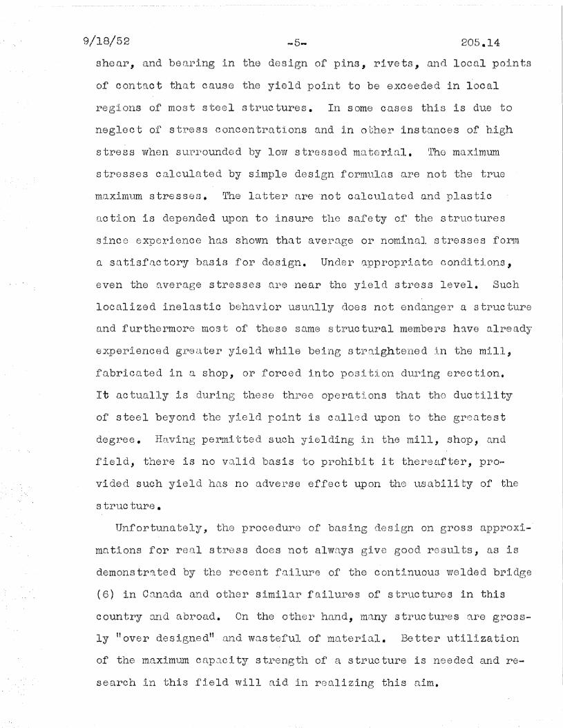
-5... 205.14
shear, and bearing in the design of pins, rivets, and local points
of C011taot that cause the yield poirlt to be e.xceedecl in local
regions of most steel structures. In some cases this is due to
neglect of stress concentrations and in other instances of high
stress Wl1.811 SUl')I~ounded lJy I,ow stl')essed mClteriQl. 11'110 maxim.urn
stresses calculated by simple design formulas are not the true
m.o..xillll1m stresses. CPhe Inttel" o.l~e 'not calculated. and plastic
tlction is depended upon to insure tIle safety of tl18 strtlctures
sInce experience ht.lS shown that aV81')uge 01'" nominal stresses .forlTI
a satisfactory basis for design. Under appropriate conditions~
even the average stresses nre near the yield stress level. Such
localized inelastic behavior usually does not endanger a structure
and furthermore most of these same structural members have already
expeI"~:tence d g:P8 f:J. tel') ~rie Id wl1ile bei11g s tl~n.igh te118 d 111 the ml11.9
fo~bricated in a shop, 01'") forced In.to positiol'l dlll')ing erection.
It actually is during these three operations that the ductility
of steel beyond the yield point is cnlled upon to the greatest
degI~ee. H[lVing pel"1mltted suc11 yIelding ill the mill, ShOPI and
field, thel~e is no VLllid l)Qsis to pl-'ol'libi t it the11 8tlfter, Pl"O
vided such yield ]).CtS no advel~se ef.fect UpOl1. the 1.lsabiJ.ity of tIle
s tl'1UC ture •
Unfortunately, the procedure of basing design on gross approxi
mations for real stress does not alwQys give good results, as is
demonstrated by the recent failure of the continuous welded bridge
(6) in Canada and other similar failures of structures in this
country and abroad. On the other hand, mnny structure~ are gross~
ly tl over designed" tlnd vvasteful of mD.ter'inl. Better util5..z8_tion
of the maximtUn capQci ty st~pength of 8,. stJ:'~uctlll"e is neec1ed and re
search in this field will aid in realizing this aim.

9/18/52 205.14
In the earliest dctys of the al~t tllo ne11gineel~" intultively de-
signed stJ~uctul')es thE:!.t, as l'l res1..11t of l'lis expel1ience and feeling
for structural behavior, had the required strength and durability::l\"
that was needed. Although theoretical analysis is now a part of
all design procedu~1'0, expeJ}ience is probably s tiJ.l 0110 o,f t118
majol"l factol')s in specificatj.on vvritirlg. Speci..:ficatiorlS 0.1')8 p]?i-
ma"ri1"JT the codification of goocl prac tlce. As the 8n[~j.,11eel') leal"ned
analytical methods of elastic stress analysis and coupled these
with laboratory test results on the strength of materials and
stl~11cturQ].. melnber's, hIs attention was more an.cl 11l0r}O C1J:EtWl'1 to tIle
individual member rather than the whole structure. Now the trend
in analysis and in the laboratoDy is buck to a oonsideration of
the C omple te s tI)llC tl11"8 ra ther than the il1.dl,Vidu\'J.J~ s 'blotlO t 1.1I") 0.1
component~
Pl~IS tic an.nlysis In design" a.s (~~~plierd to tiOl'"l bl1ildi.ng frames,
was foresh£tdowed by the appl1oximn.te _so-c~~,J... le(l lIo1o.st~c" mot110ds
of anEllysis tl1.~;,t crane into 1J.SO early In tq.E? cer.ltuJlY 1'J or tl1e pur
pose of CiJ.lcuJ_L.l.ting stl'18sses due to Itl.te)~fJ.J. Wi:r1d loads. Tl18se
methods have been reviewed by Clyde ~. Morris (7), As early as
].908 met110ds of D..l1.alysis werle 1.11 use based 011 l.lS8umptiona th,J.t
the points of contraflexure in colwnns were at the mid-height.
Suel1 assl.lm.ptions may J.ead to .'J. final design ylGsul t similar to
thu'G obtained by an arlalysis which t3.ssumes plastic l1il1ges to
develop at the endMs of tllG COltIDlns.
2. T~e Q11~£_taint:'l £: Mat~i~!. ~110.PE:!!i~ ~ the lnel~tic Raq,~
IJ:1 the eJ.Gs tic rElnge of~ bel~avio11, up to loads allowed in 0011-
ventional design, the deflections are very largely determined by
the elastic moduli of the mateI'~i[ll, n constant that va.ries for
steel wi thin ret tiler l1Cl.rrOW limi ts. Bttt ill the plas tic r,2nge" t11e
primary factor determining the structural load-deflection re-

.. 7...
lati 011Ship 1s tIle lOVl/el'J yield level of s true turnl steel. Tllis is
il,lus tra ted by t11e plas ti.c 'bendil1g bol1l1vlor of tlle wide flange
structural shape.
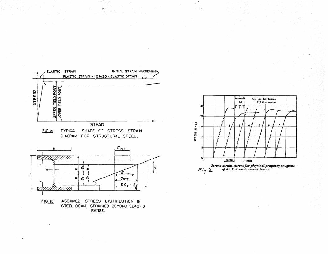
small portion of the typical stress-strain diagram for structural
steel in the int tial pleas tic ral1ge up to the bo{gin1'1ing of g8118I'al
stral.11 hal'1(lerlirlg. Fib. 2-b may serv'e as an inclication of tl'l(~ .fact~
that the pIns tic b8!ldlng resis ~tarlce ]ral'~gely may be retll:i. zecl wi th-
out~ US:Ll1g 111uch of the J~O'V11F.J:rl :y'ield range that: is avaiJMable. 'me
lower yield level is of obvious importance in plastic analyses and
may be defined as that level or stress just sufficient to develop
successive new zones of plastic slip in the portions of a test
specimen that remains in the elastic st~te. Fig. 2~ taken from
may exist in a particular steel at a particular cross section of
n wide-fla.llg;e s11ape. Iieepirlg in mind the ftlC t -cha. t 1111.11 tea ts in
gelleraJ.. ar~e l-lUll ,Qt a 1')8.te oj~ stl'~ ..2in ~t;hat gives a relatively rligll
yield level estimate, it is of interest to examine a large body of
test inforlnatioll furnIshed through courtesy of the Jt.lckson & rvIore-
lCL11d Compa.,n~r. TIle se resul ts al'lO platte d in F1ig. 3. 110re than
3~OOO uliJ.. l tests 1J\lel'le analyzed showing a vD..r~iation of -15% to +25fb
from the average yield strength level of 39,630 psi. Mill test
r l 8su,l ts are bas8cl 011 the upl)er ~rield poi~ rLl..tl1er tl1a11 on the
lower yield kve1 arld the In tter is 1110re slgnificant in the plD..s-
tic behavior of str1:tctural luembers. 'J.1he erfective str~ess strain
properties of the material are further modified by the existence
of residual stresses caused by cooling, welding, or cold bending.
Theories of lni tio.l Inel[lstic Y'ield..... \ ~ ~_~~................ ~~~~n~ ...~~.
Tl1ere is curl'"lently much intel~est i11 theol".ties llnd eJ~per~:tlnents

9/18/52 -8... 205.14
to deter~nli.l1.e ·the conditions for e.xper~imental "law" for.,j.,ni'tial
yielding of stael or othor metals in a state of combined stress.
Sucl1. laws, hO'N8ve r, Ctl)e not; ge1:1el")ally require d .for ti11e px-'edic tl on
oflt~he ille 18.8 tic beh:1vi 01.... of bo o.nls, colurnns, [lnd te11S 1. 011 lnembe rs ,
Such structural members are governed primarily by unlaxi~l stress.
In other words, the load carrying part of the stress system is
one in which two of the three principal stresses arc zero or
nearly SO~ The ductile behavior of material ill suell fL UJliuJtlal
stress system may be based on the properties determined by the
simple tensl011 or oOlnpression test.
4. Deflection us a Limitation in Design~~~.....__:r.-c-_----. ~........... ~_..._.__ n_ ..~~One of the principal advantages of plastic analysis is the
simplici ty by w11ich nlCtximum load cap-'.lcl ty may be deteJ:mined as
compared with procedures of indeterminate elastic frame analysis.
If def)lections must be ca.J,.cl11at8cl, IntlCh o1~ this adVElntage is lost,
and it must be recognized that deflections do frequently control
design, whether it be based on "elastic ti or Itplo.stic ii anfl.lyses.
A structure that deflects easily is a flexible struoture and
motion due to vibration may produoe undesirable reactions on the
part of occupants or imprope~ functioning of machinery. The
upper floors of a few tier buildings are unsuitable for oocupancy
because of larze Inovements that occur~ during wincJ~storms. Struct
tlral melnbel~s supporting moving or dy11Ftnlicrtlly applied loads mus t
have certain rigidi t~r\ to per~mi t pr~oper functioning of lnovin.g 8
quipmen t. Exporience wi th OV81-'ly flexi l)le suspenslon bridges is
well known. Tllere ls a need for mOJ~e l"'ational determination of
proper~ l'imi ts to defle c tion in vnri OllS S true tl1ral applieD.. t:i. ans
~~ a need that will be intensified in the advent of plastic de-

9/18/52 --9- 205.14
sign proceclures.
In elastic design, deflections can be computed with a reason
able d_egree of certainty in tile elastic working loacl ral1ge. In
the plas tic design pr·ocedl1re such certainty is not always possible,
F1igure 4, taken from another Lehigh report (13), COrl1r)ares t118
theoretical. and test results 1101" a simply supIJorterl 14 VVI.7' 30 bealu
with cantilever sections ext~nding beyond each support loaded so
as to simulate a continuous beam between supports. In such case
the theoretical curve for load vs. deflection S110WS three straight
line seglnents. The first bel1d in tIle theoretical Cl.lrVe starts
when the yield moment 1s reaehed'at the supports and the second
bend occurs when t~e yield mOluents ar~e pflssed at the centel~ of wbhe
beam span. Tes t results in the particu]~ar case illl,18 tl'"la ted fall
fax· ShOl'"'t of the theoretically COmI)llte rl 11alues. The initlal diver..
genae from the theol'"letical ValtleS in the elastic l~Qnge is pT1imarily
due to residual stress and the lowered strength in the plastic
range is due to local and lateral plastic buckling of beam flanges.
This result is not necessarily typical but illustrates the diver
gence that may occur under condi ti011S favoring plastic bl1ckling.
In the case of a l)eam wi tJ~l heavy flarlges and corresponding
good resistance to local buckling, with the beam also supported
against plas tic latex~al buckling, tlle theoretical cur~ve might be
exceeded by the test curve.
Load deflec·t,lon C1'..rves ShOWYl in Fig. l5 are for tvvo of the
portal frames tes tee} under vertical load in arlother phase of tl1e
Lehigh investigations (11). Deflections in ~ach case deviated at
low loads ~rom those predicted by elastic theory. Frame No.1,
made up of 8 WF 40 members, however, developed the full pla~tic
strength predicted by sifaple plastic theol~Y. lilralne No.2, made
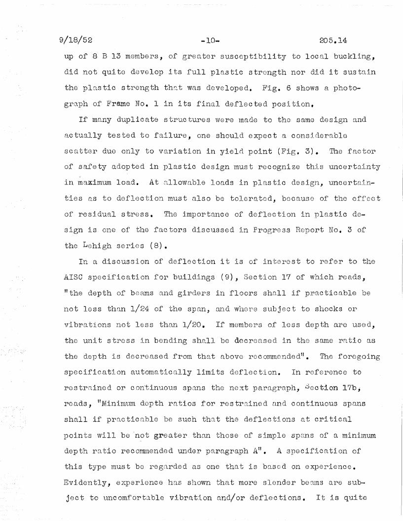
9/18/52 -10.. 205.14
up of 8 B 13 members, of greater susceptibility to local buckling,
did not quite develop its full plastic strongth nor did it sustain
the plastic strength that was developed. Fig. 6 shows a photo
graph of Frame No. 1 in its final deflected position.
If many dupli c a te s 'trt,lC ture s we re lnade to the s arne de sign anrl
actually tested to failure, one should expect a considerable
scatter due only to var~iation in yielrl point (Fig. 3). The factol~
of safety adopted in plastic design must recognize this uncertainty
in m;ct:x:im1.lln load. At {'l11oWLlbJ_6 loads in plas tic design" uncert8~in
tie s as to deflec ti on mus t {lIs a be tolerate d, becaus e ofj tJ:18 e.f,flec t
01' residual stress. T116 impol'"ltance of deflection in plastic de
sign is one of the factors discussed in Progress Report No. 3 of
the Lehigh series (8).
In a discussion o.f deflection it is of interest to I1efer to t118
AlSO specifioation for buildings (9), Section 17 of which reads,
"the depth of bcan1s Q11d g:tl'~(le]~s ill floors sha.ll if prete ticnble be
110t less than 1/24 of tIle span, Ul1d '1Vllol~e sr~bject to S110cks Ol~
\Tibrations not less than 1/20. If TIlsmbel'"1s of less depth are u~sGd,
the unit stress in bending shall be decreased in the same rntio as
the depth is decreased from that above l'"locommended". Tb.e fOl"egoing
specification automatically limits deflection. In reference to
rostrained or continuous spans the next paragraph, Section 17bj
l~e[tds, "Minimtlm doptl'1 r~Qti.os for restl")8.ined tlD.d continuOl1S spD.ns
shall if pJ?CtC ticQhIe be SllCh t11tt t the deflec ti 0118 at cri tical
points will be 'not greater than those of simple spe~n.S of) a miniln1..U11
depth ratio reco~nended under paragraph AU. A specification of
this type must be regarded as one that is based on experience.
Evidently, e:x:parience llE.tS s110Vln thE).. t more slend.er becuns 8.1")8 sub..
ject to uncomfortable vibration and/or deflections. It is quite

9/J.8/52 -11.. 205.14
probable tho. t i.n many cases n s tl'1UO ·b1.lre des ign by plas tic pro
cedures might actually meet this specification because of the re~
duction in deflection produced by continuity even when plastic
design is considered. This fact has been discussed in Lehigh Pro
gress Report No.3 (8).
In summary, the following may be said regarding doflections:
1. In cases where experience, as reflected in
existing specifications, hus shown a limita
tion of deflection to be desirable, it will
be necessary to consider deflection in the
application of plastic design.
2. In cases of plastic design wherein the
working loads are considerably greater than
those for elastic design, an unavoidable
degree of indefiniteness in final deflection
8 4 t wo;rking load 111US t be toler~':'lted.
5. Resistance to n1o!nent in. the Plastic E~ange___• _ .....~ ...~ ~~~ ;J~ -......__... _
In the simpJ.. e plas tic theory it is assumed tha t "l1.inge-momen ts"
successively develop at poj.nts of maximum moment in structur~al
members. The approximate calCl11atlon of maxi-mum I.oad is then
based on the strength of the structure incorporating such plastic
hinge momen ts • In view of the 0 bvi 01.:1.8 importance of plas tlc bend
ing resistance, the following will outline and discuss in brief
some of tho fae tox-'s tha t mtly aff~ec t t118 beha.vior dur-ing i9.nd sub-
sequent to formation of hinge moments,
5A. Cross-sectional Shape and the Stress Strain Diagram~ ...lttl.i.. ~~ _ ..~_ ~ ......~~.........il4'J.111A;~-...-. --
Annealed structural steel has a nearly llnear stress strain
diag~L~am up to tho yield level a:ftex~ ¥l!lich strail1S of 10 to 20
times the elastic yield str~in occur with no increase in stress 8

9/18/52 -12~ 205.14
If a s true tural steel beam is under pure bendi11g mom8nt, it will
stal'")t to yield wb,erl tb.e fibers furthest fl1 0m the neutrttl axis
reach tl1.8 yield point. (Fig. 1) After ini tial yield tl1e l")elation
betvleen load D.ne). deflection of' the be~J.m wil.l be nOl1.-1ineD.l'l b11t
the beam will 1"6Sist i!lCreQsing moment npproaclJ.ing the "hinge...
mornent" CtS yielding penetl')D"tes to'l\Tard tIle D.6utr'8.1 aJ<:ls of the beam.
1~'1e ratlo of tb~e hinge monlent to the moment at initial ~vield is
SOlne time s ter~mG d the U shn.pe-fnc tor" of the beam. it 1Nide flange
(VvF) stl-'1J.cttlral sectioll usually has a shQpe-f'actor betvveen 1.10
and 1.20. More compact sections have larger shape-factors; for
example, Q re:ctangu]~~J"r bOa,TIl 11[18 a SllQpe-1')[lctor of 1.50. Standt1rd
I-beam shapes vvi th 110Qvy vveb t~lnd slnctll flt1nges "viII ha.ve greo. ter
shape-factors "bhan vifide .flEtrlge sections wlth thin webs.
In addition to the effect of cross-soctional shape, there may
be secondary effects insofar as sh~pe affects the tendency toward
local buckling, lateral buckling, failure by shear, etc., as will
be discussed horeln[lfter ll Tlle C,9.1Cl11at:ton o.f the moment..-angle
curve from a given stre,$s str.:lin dlagl'43..m 1"lor a wide flange section
was dlscussed in IJehigh Pr'ogress Report J:fo. 1 (10).
5B. Effec~ of Qb.e~r
If high shoar exists in the web of a structural beam oyer a
considerable length, as in the case of a $hort beam centrally
loaded, or a long beam with a concentrated load near the end~ the
beam may yield rather generally in shear without reaching the
usual hil1g0 mamen ts that f11'18 as smne d in plas tic des 19n. This
problem of shetl.r as a px~im,zLry design consideratlon will be dis
cussed separately as Section 7 of this report. However, in the
case or shear combined with large moment, as at a support of a
continu.ous beam, the effect mcty be someWllLl.t difi1er·ent. Tl~e

9/18/52 205.14
problem is a complicated one since the distribution of shear
stress depends on the support details and the way the load is
brought into the beam at the support. If the moment falloff
r)apidly away fl~om the SUPPo11t, ini tial yield'ing due to moment may
be so localized that strain hardening will commence before any
appreciable rotation develops. In such a case, the moment de
veloped at the support may be considerably greater than the
hinge-moment predicted by simple plastic theory. In other cases,
vJhere the moment gradient is not great, shear ma'JT reduce the
hlnge moment sorIlewhat. Tl1e problem of shear in its effect on
hinge-moment has been studied by Horne (12) for the case of the
rectangular beam section and sim!lar consideration of the I-beam
sec t:i.on are now in pl'"logress at Cambr:tclge al~d at Lehigh Universi ty.
50. Ei'fect of ~?Cial Load
The efi'ect of axial load on moment capacity for val')ious comb
inations of erld moment and restraint are reported in Lehigh l)rog
resa Report No.6 (13). In general, the effect of axial load is
to reduce the moment capacity of a wide flange structural shape.
However, the effect is relatively small in certain cases of small
axial load, small l!r ratio, and compact cross-section.
In a building fra.me, elld moments are devel.oped in col1...lmns and
the combined behavior rrlay be repl')esented by an fi intel'"lc.1.C tionU
curve in which plotted points represent simultaneously the rela
tive proportion of ~xial load and -bending moment at yield or
maximum load. Figure 7, tmcen from Progress Report 6 (13), shows
the interac tion curve for rl particu].ar case wb.erein bending moment
is applied at one end vlh:tle the other~ is held f'ixed. The '~pper
line indicates the theoretical ultimate strength of a very short

9/18/52 -14- 205,14
column wher~eas the test results Qre .for an 8 'NF coll:unn with l/r
of Ill. It may be seen from the test l 1 esults that initial yield
and column collapse may OCCllr a·t londs less even than those cal-
Cl11a ted for inl tial yield by the secant for~mula. rrlhe tes·t re
sults are not typical of those that may be expected from other
combinations of applied load, moment, and slenderness ratio but
illustrate what may occur under certain critical conditions
co~pled with residual stress and local plastic buckling.
In ordinary pOl'ltal fr~ame columns the ratio of axial to critical
load is usually small so that any reduction in hinge moment may
be ignored as is done in most studies of collapse strength. How
ever, in the case of tier building structures, the resisting
moment ofl the columns in tllG lower floor)s would be reduced by
axial load and any evaluation of collapse strength in such a
case should include consideration of this effect.
5D. Eftect of Local Flange Buckling- - _._.-- --- "--'.'--
As reported in Progress Report No.1 (10), wide flange struct-
ural shapes have a flange thickness sufficient to insure against
elastic buckling and will therefore develop the full yield
strength of str1.1ctural steel, except as modified by prior plastic
bucl{].. ing induced by residual s·bress. If the bel1dj.ng moments are
uniformly dIstributed a.long a considerable length of beam as in a
uniformly loaded be.o.m wi th mOluent-free supports, or as in case of
concentra~ed load~ ~quidistant from the center-line, large de
flections occur bef9~e local deformation results in marked plastic
buckling of flanges. However, in tests of continuous beams, the
more localized moments over the supports result in considerably
greater local rotational deformations than for the simply s-upported
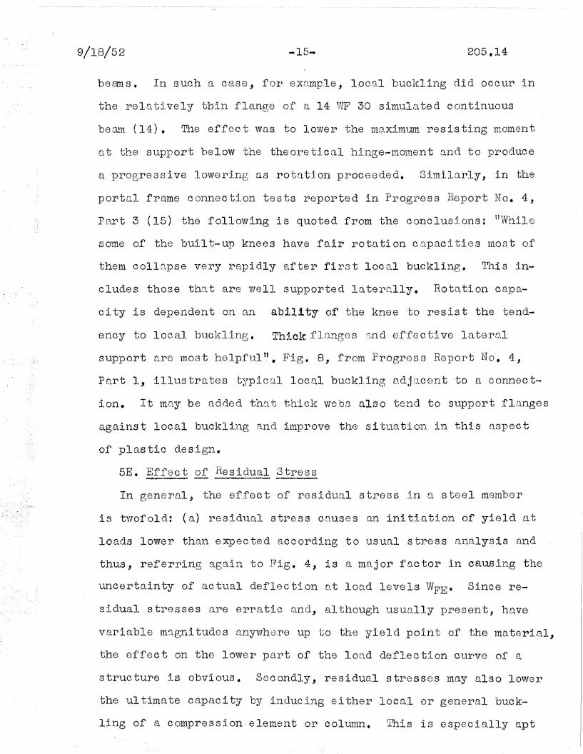
9/18/52 -15... 2C)5.14
bea.n s • In s UC11 a case, for l, exrtrnp].e, 1008.1 buckJ.ing rlid oee ur in
the relat;lvely "bb,in fla11ge of a 14 '~lF1 30 simulEl ted con.tinuOlls
beam (14). Tl18 effect was to loweJ~ the rIlo.ximum resisting nloment
nt the support below the theox-eticaJ.. hinge-molnent .!3.l1d to produce
a progressive lowering as rotation proceeded. Similarly, in the
portal frame connection tests reported in Progress Report No.4,
PS.rt 3 (15) the following is quoted fl~om the concluslons: ilVVtlile
some of the built-up knee's hL\Ve f[tir 11otation cttpacities rnost of
them collQpse very rapidly after first local buckling. This in-
eludes those th(~ltare welJ. supporte.d lQtel~[111y. Rotation cO.pa
city is dependent on an abi11 ty of tIle knee to resis t the tend-
sney to local buckling. Thick flanges and effective lateral
support rll~e mos t helpf'L1.1 '.'. Ii'ig. 8, from Progre s s RepoJ:t 1\1" o. 4,
Part 1, illustrates typical local buckling adjacent to a connect
ion. It may be added that thick webs also tend to St~port flanges
against local buckling and improve the situation in this aspect
of plastic design.
5E. Effect of Resid.ual Stress___ _ ..... ""*' --=_ .. ...-n_
In gener"Ja.l, the ef.fect of residual stl")6SS in a steel member
is tvvofold: (1'3.) resid11al stress C[tuses an ini tiution of yield at
loads lower than e.xpected accordlng to usual stress tl11Ellysis c:tnrl
thus, referring again to Fig. 4, is a major factor in causing the
uncertainty of actu~a]. deflection Olt lO£td levels WFE • Since re
sidual stresses are erratic and, although usually present, h~ve
variable magnitudes anywhere up to the yield point of the material,
the effect on the lower part of the load deflection curve of a
structure is obvious. Secondly, residual stresses may also lower
the ul time. te capac i ty by indue i11g e i thel~ local or gener~al buck
ling of a compression element or column. 1'his is especia.lJ..y apt

9/18/52 .... 16-
to occur if the elements are of intermediate slenderness between
the elastic buclcling (very s]~ender) rr.:lnge, ancl the very short EU1d
COll1-l)ClC t Inember tllQ t will develop full plas tic yleJ~d strength even.
in the presence of residual stress.
The principal sources of residual stress are:
1. Uneven cooling of rolled structural sections
:lmmed.iately after rolling!)
2. Cold straightening, punching, shearing, or
bending of sections.
3. VVeldil1g.
The effects of cooling ,l.?rld cold l)ending residl1.al str-ess htlVe
been disc1.1SSed at some lengtb. trl T.Jehigh Pl~ogress Report 5 (14).
Effects of iJ\181ding residl1Ctl str'0sses have bee11 110ted In Pl'1ogress
Report 4 (15) wherein residual stress is considered to have been
the cause of local. pJ.nstic bucJ:r.l,ing f[lil'.11~e in the hflunc11ed knees
along the innexl compl'")8ssion f1lo.nge. l~t tllis locatio11 the inner)
flange 18 n restrained compression member and it is known from
the recent cOlum11 tests and st11dies at Lehigh that the residual
stress causes eCtrly ylelding of t11e outer fibers of rolled flange
sections, thus reducing the effective column section. Local buck~
ling first occurs ,~lt the poln't of maximt,1m stress. If this region
is lac ali ze d r3. t the jtulC ture be t\1\leell the haloU1ch and 11 011ed sec 'bion
and If adequate latel'1aJ. support is pJ~ovi(led at this point, the
adverse effect of residual stress on the rotation capacity of the
joint might be offset.
5F. Eff~c t of) La tGl~a!. ljuc~inPi
In plastic design the concer'n is primarj,ly wi th plD,stic ].atel~Lll
buckling rctther than elastic lateral b11ckl:tng Wlllc11 is guctrded

9/18/52 -17.... 205.14
against in usual structural design by proper proportions or by
10wel~ing O~l the D.l1owable stress as in the case of oomp118ssion
m81nb(~rs. ObviollSly" in p]~~""l.stic design, pJ~oportions of a str~uct-
Ul-le ml1st be sl..lch as to eliminate elastic bllckllng o:£', any type, in-
eluding elastic lateral buckling•. Considering only plastic be
hav:tor, local an.d/or later1al bllckling ma.y lower tb.e effective
hinge moment in a continuous beam or frame member and may reduce
the moment value during continued rotation in the plastic range,
thtts preven ting tIle re ali zation of the fl111 pILls tic s tr~eng th of
Many tests of frames in the plastic range, often on small
models, have involved solid rectangular bur sections bent in the
weak plane (3 , 4). In such a case local and/or lateral buckling
is not a IJroblem. Tests by Brt.!{8l" ancl his associcLtes also Inolude
small model fl'l[tmeS using "vide .flt111ge sections bllt the extJ~apol,~-
tiOll oil these results to f1.11.1 si.ze stru.cttl1"lal members ul1.d frnmGs
is questionable. Work at Cambridge recently has included tests
of ne arly f1J..ll.- size con tinuOl1S frnlue s • r~J.1'ne wOl~k a t ]~ehigh has
put first em,phr:l.sis 011 tests of Ilearly fUll-scn.le models of struct-
urea, simulating actual practice as closely as possible. Results
of these tests llCive emphn.slzed the .need for o.dequate ID.teral
support if plastic analysis is to be applied to design.
5G. Shape of Cross-section and Longitudinal Distribution~ _ ~ .~L"'. ~' ..~~ ~\-"'-- """\.<~I~'to""""'-"RU",,_ 1Ib-,,~~""'~r:IIl-
of ~~1~..~~!~
The solution of problems involving bending combined with tor-
alan and/or uns:vmmetrical bendi11g becomes extI"~en~ely complex in
the plastic range. Furthermore ns the plastic range progresses
the shape of the cross section may chnnge considerably due to
local buckli.ng and!oJ: crippling or crimping SUC11 as 111i:gb,t occur)
9/'18/52 -18- 205. ].4
when n round tube is bent to a sharp angle. In general the con
tribution of bending to resistance to lateral load will decrease
after) a certain l~mount of pJ.a.s tic deforrrlD. tio11 [tnd "th(~ fUl"'ther
J:8sista.nce to lo.tel~[ll lOD.. d will largely depencl on the concl:t.tions
tl1at obtD.irl at the EJUpports. If the bearn is D.. n1emlJel~ of n con
tinuous structure with the sl~ports co~strained against lateral
moveUlent 1i c o..torlLtry" D.ction nl8.Y develop ill which latel~3.1 components
of t118 dil~ect tensile for~ce induced by lal'lge clef,J.. ections may oflfer
the prilnrJ.l"'Y re s is tflnce to In tel'"'rll load. S1..lch letrge clefle c tl 0118
could not be tolerated as a basis for usual design but might be
coxlsiclel'")ed in connectIon with res:tstc.rlce to l)omb blQst l()[lds ..
All of the se fae tOl'lS are complicD.. tJng Inflll.erlCes iJ\Jhen plas tj~c
analysis of a structure is considered. It is probable that any
initial considoration of plastic design primarily should make
use of s'JTlTIlnetricfll sections c0111binecl vvith 1.oo.clln.g 111 eithGr~ prin
cipal plane. Plate girders with variable length cover plates prob
ably woulcl not be deslgned ctccol'1ding to plastic t1180ry stnce the
distribution of th~ material is based on distribution of moments
and the elastic and plastic designs therefore would lead to app-
rOJcitno. tely the saIne \'Vcight of s true ture. Anotl'ler eff~ec t .l1[tving
to do with malre up of member is the possible llse of built up
welded girders made up of rolled platos. These, because of
greater depth, mcty not behave simil,=11'11y to smaller l"()J~led 'Jvide
flange sections and the problems of local nnd lateral buckling
will be more acute.
51-I. g~ .2.:f. ~ncr:l;~e1!+£nt
The use of fire proofing or th.e encaseme11t of steel member~s and
connections for other purposes such as resistance to corrosion may

9/18/.52 -19... 205:;14
have a considerable effect on the plastic hinge moment and rota
tion capncity. These effects have been studied by Batho (16) but
more research of this type is needed.
6. The :Oes_ign ,9f De tQ~ls
It is generally r~ecognized that trle most important problems 1.n
structural design concern design of details such as connections
rather than the design of the main members, Main members are
rather thoroughly covered by specifications, but in the design of
de tails tl1e e11gineel~ is called llpon to exercise the greates t a
mount of individual judgment and the wisdom that comes only
through experience. Here, in the details~ the engineer departs
the fnrthost fr)om eltLstic stress analysis procedures and either
by use of approximations based on his own experience and judgment
or by use of existing specifications where these cover the case in
hand, plastic design in a restricted sense has always been used.
A typical example is th8.t of tIle desi€~n for tIle local compl~essive
stress in D. bemil web c.tbove a sllpport or ul1der n conC811trrltion of
load. An Qverage stress here of 24 kips per square inch is allow
ed by the l~merican I11stitute of St~el Constrtwtion Spec1flcatlons
(9). VVhe11 Q beam is supported on a seat D.LLgle there is n. concen
tration of stress at tb.8 very tip end of the belJ.m 80 that 'the
yield point is reached at r~f)8~ction lotlds wrJ.:tch may be lower than
the allowable loo.d as c ttlCl..lJ~[l te d by tl1.8 empj.. ric 0.1 formulLls CU.rl""\en t
ly used in design. ~lis fact has been corroborated by unpublished
test results based on work done at Lehigh University in 1941 (17),
Fig. 9 shows the measlJ.red stress di.stribution for these tests of
cen.trnlly lOB~ded short 12 'iVF 50 beams, indico. ting a rE-)n.ct~:i()n of
about 22 kips at initial yiold. (With loose top angles the re~
ftC tion a. t i11i ti;3.1 yield wOl~ld be much lower)). The a.llowable end

9/18/52 205.14
reaction of the beam would have been 45.6 kips. (The AISO Speci
fication seems overly conservative as it would automatically
limit the design (reactlon load) to 35 kips in this case) •
l\feilertheless, in the test, the on.ly evidence of fo.ilure was a
grnducl.l spr~ead of' the yielded zone from the end of tb.e beam
towal'ild the toe of tJJ.o seat t.l.ngls lJ T11is spl"lead VVn.S appreciable at
40 kips but the beam continued to take 1.oads 11p to 80 kips wi tb.out
serious signs· of distress~ Figure 10 shows the spread of yield
at the 70 kip load and Figure 11 presents curves of reaction va.
deflection at the connection for the various tests that W01'")8 re
ported. ii.bove 80 l{ips the compression yleld in the web of the
beams had spread to SllCh Ci.n extent tb)~tt be.rely perceptible local
buckling developed as indicated by dial gages but not to an extent
easily noted by eye. 4t maximum load of 90 kips lateral buckling
amounted to a~pprOXilnQtel'Y 1/10 of an inch. L-it tb.is load the beams
had failed rather generally in shear and the tests were stopped.
Vii tl1in the rU11ge of 'the tes t pl'"Jogrnlu the type of seat ha.d no
marked e.ff'ect on ul ti111[lte capaci ty and ilISC Specification prnctlce
for beam. desi.gn was shown to be consel"~vati'Te.
Many other examples could be given similar to that of the seat
angle connection. In general, where local concentrations of com
pressi.ve stress exist D.nd 'VI/here thore is a su,rrounding region of
low s tressed rna terial or ad,j e.cent parts in a blliJ~ t-up member, so
as to prevent local buckling, loads many times those causing
initial compressive yield may be withstood without seriouE de
formation of the structure as a whole. FUl'ilthermore l in these
cases where the stress l8 predomin_antl~T compl'essive, tl1ere is
little or no danger of failure by fatigue or by brittle fracture.
Other similar cases lnclude tl'18 desie;n of rivets and pins in

205.14
shear, bearing, and (in the case of pins) direct stress due to
bending. The high allowable str~ess. in pins for direct stress due
to bending (30,000 psi by AlSO Specifications) may be justified
by the 11igh shape fEte tor for the c IJ~cltlar s eo tion 'Nl11ch is 1.70.
Considering plastic behavior there is thus a factor of safety of
1.70 x 33 = 1.87 which is greator than the value of 1.65 as snnc-30
tio11ed by Ij,ISC f or tellS iOl1. members CIt In tl10 C tlSe of the l'"\i ve ted
connection, t110 stl~eSS8S [lllowed In b(~ar'i11g and sheCll"l vV0111d pe~r-
mi t local yield1rlg in an ill(11'vidllal l~ive t a.nd adj aceXl t plnt-;e J
were it not for friction between elements, and, furthermore~ in
the case of a large connection with many rivets, tho end rivets
are known to be stressed at much higher IGvols than those in the
intel"ior. The outer r~ivets mllst yiold .9.ncl defoT'm fiJ~st, tllUS
causing a l'leclistributlon ofl load to tile v8.1'ious rivets thLtt is
entirely analogous to the successive formation of moment hinges
assumed i.n the plo.stic n.nnlysis of tl1.0 continUOtlS frrlmE.:.
Since the d8sign of structural details is already based on a
restricted application of plastic design theory, 'it is obvious
that in the advent a.r a broader) application of plastic design no
gl'ea t change is to be 0xpec ted in this vel'"~Y impol~tant aspec t of'
structural design. It may be necessary"for the engineer to give
even more careful consideration to structural details if an over~
fill baJ~anced plL1s tic s tl~(:111gtr.l is to be l'lenli zed.. This has been
particularly evidenced by the tosts of various knees for portal
frames as J:eported in Progress Report 4 (15).
7. Shear as a Primary Desi~n Criterion,_,._._ ......,,~ ..................-"f"_J~rtI..... ~~_. .\.......__...........,-.11'
Shear as a factor in altering the moment strength of beams has
been discussed eal~lior but she,:.tr in 1 tself may be the primary COll.
trolling factor in beam Ol~ fr~(2111e cleslgn. In their review of

9/18/52 205.14
progrtess in the pll~stic methods of structura;l nna.lysis, 'Symonds
and Neal (5) state ft s hec1.r forces can be neglected except in cases
where the ratio of span length to beam depth 1s less than abOl.lt 4
to J., which is much smalJ.er than commonly usedu • The authors have
confj~rmed by correspondence that in using the term "span" they
"had been thinking in tel'')nls of cantilevers or dis tnnces between
plastic hinge locations in genel"'altll) This i11tol'1pretatioll is
corroborated by the fact that it may be shown that ratios of
total span length to depth of 8 to 1 or more may be controlled by
shear fo]~ currentJ.y use~ vvide flB.nge sections under symmotJr~ical
loading when fixed at each end. In the case of a concentrated
load neo.r tIle StlPP01'1t of a beam restrainEjd at the ends, shear may
be the primary design criterion' in some cases if the load is at a
distance less than four times the depth of the beam from the near
est s\~port. Such lond arrangements may OCCur in the use of off
set columns in building frame construction.
Cur'rent "elastic" design specifications of ,,~~ISC permit a lower
faotor of safety with respect to yield for shear failure in the
web of beams as compared wlth moment failure due to direct stress
in the flanges of longer beams. This WaS brought to the attention
of one of the authors as a by-product of the tests on seat angle
connections previously referred ~o (17). In the test set~up a 12
WF 50 beam had a span of 5 ft. face to face of supporting column
stubs. ~s an appendix to the report on web crippling at seat
angle supports, the following comment was submitted by one of the
authors and is quoted in part and with minor revisions as ~ollow8:
"118 a side light on the recent tests of s110rt
beams supported by seat angles at each end,
certain facts have been noted regarding the

9/18/52 .. 23- 205.14
failure of these beams by shear.
n .L'i t a total cen ter~ lOLl.d of 170 kips 01~ 85 kips slleal~, each
beam had yielded rather generally throughout the beam web
area. The aV81')/lge s118ar s tr~ess at fail1.1re, based on gJ,"1oss
'\Iveb al~ea, thCtt is, ber-un depth "dl1 tiTnes tl'1ickness trw" 1
gives an Q'Terage 8hetll~ stress o_t f[111111'"'e of 19.1. lclps per
square inchd There is thus a factor of safety with res~
lJec't to the al1owabJ.e avel~o'ge stl~e8S of 13 kips IJer squa!~e
inch of ol1.1y 1 0 47 as compn.l~ed with tIle llsual safety factor~
of 1.65 :r'eJ.ating the permissab"le tellsiJ_6 stress of 20 l{si
to the mininlUlll specifl:i.cation yield vD.lue of 33 ksi. IIow-
about 40 kips par square inch, therefore, the factor of
safety w0111d 0111~l be 1.21 if ndjustecl to the nlin5.mull1 speci
fica t:i.o11 of 33 kips per sql1ar~e inch.., t1
The CiO tl1al maXilTIUTIl shet?tJ~ s tl~ess at fCliJ.tll')8 a t tIle center of
the web (neglecting stress concentration in the fillets) was 21
kips per square inol1. by ·the fOl~lula,
v = VZ *"2I1JV (1)
* It is of illter~est to note that tIle tnQXi111l.Un ShO,:Ll~ stl')8SS is tsOVerned by the static mome11t of ~Ghe SOCti011 (2) Wllicl'l also c1eter....mines the plastic hlnge nloment value. If plB~stic desig11 becoluesmore prevalent it vvil1 be cl.esirable to :i.nclud~e In strllct11I)o.lllfL1.1dbool{s v,'J.lues of Z for 'Jlrl~1 sections Vvllich CLln be tlsed botl1 i)ox~ deteJ~111il1ation of M.o rU1C} ll):'lx:i.nl1.lm sl18Ctr stress Q ii c011venient apPl'loxi-ma.te foxl lnuli3. .for- "Z", the s tn.tic mOlllent 01" the complete sectJ..()n,use:fu].. In maXim"L1ffi sl1.cal'",) Stl"'l8SS tlllcl l::>lastic lnt)lnent (leterlnl11atioll is:
d = depth of wide flange shapeJi = total aroa
l!w = web area = dwt - flange thickness
Mr. Wc.11ter VVeiskopf' 11.EtS poi11ted Otlt tJ1.r.t for those 811[~tpes whichare spli t longi tudi11c111y to .fOI"TI1 S tr~11C tl1I~tll toe s.. tl'le {LISe lVIanl.lalgives the loco. tion of tl1.8 neutr~ctl ~xls o:c t118 11ulf- sec ti011. Tl1isperraits accuro.te [l11(1 sinlple C01111Juto.tlon of Z l'"lox~ the pal""entsection\)

9/18/52 .... 24~ 205.14
If the allowable valuG of 13 kips per square inch were for the
maximum shorn') stress rather thun the ~~v~~ the factor of safety
would be 1.61 for the bertln tested \~lith n web material l:1aving
yield of 40 kips pel' sq.uare illCl1. ~r11is" when adjus ted to the
mimimtUTI :lield vnluo of 33 kips 1,)81' squB.re inch gives a fc..lC tor
safety of 1.3, Rven this is low compared with that usual for
d.irect stl'")ess in ela.stic dosign. It may be noted tl:10.t tllGSe beams
failed at a shear stress level loss than that predicted by the
shear str.').ln energy cl'litel"lion 011 U oc tahedl'1al shen11 stressUcrit··..
erion of failure which prodicts yield in pure shear at 19.1 ksi
for 0. rna terial vvi th a yield of 33 ksi I .d.ssuming tl1.G optim:i.stic
prediction of the octahedral shear stress theory as the criterion
of yielding in the web of rolled b03.1i1S, f1.11 ullo\1\Jable ma~1.!n~ shear
stross of 11.5 Itips per sqtl.D.l'1e inch i.s in(licated for a factor
snf'ety of 1 0 65 0
The foregoing rernQl"lks concerlling shear i.n beams may serve to
give added emphasis to the fact that in some cases shear may be
expected to be the controlling design criterion in plastic design
as well as in C011V811tional fielastic fi dosign.
8. The Limitation of Failure by Fatigue,___. 'JII*4L~__ -...n.-.~ ...... .......~_~ ~ ~.__".
TIle importance of fa tig11e or repeD.ted load as Q m.odifyil1g

9/18/52 205.14
limitation on design of beams in the plastic range is apparent
to a render of the slm~ary report on University of Illinois
fatigue tests conducted by ~rofessor W.M. Wilson and his assoc-
iates as reprilltod in the VVe]..d~_ng~~~nal (18)~ 'l'here Is, never-
theless, some grounds for encouragement on the part of tho.plas
ticity design oxponent for the case of any structure designed for
100,000 cycles of load or less in which the lond goes from a
minilnl1l11 s tre s s of ze ro to D. TIla.ximUJ.i1 vr..lue (f In thi s range bo :.1m
sections fabricated with uniform cross-sections and with contin
110US 'Nelds had. fo.tlg11o stl'"aongths in 1tvJ:lich the initi,3.1 stresses
were [lbovo the yield POi11 t of tl1c mo.:torial..; On the other l1nnd,
b"Llil t .... 1.:tp beclms vITi th r)o.r~tiD.l 1.GIlg"t;h cover pln tes ~ such as ,~l"e
used in elastic design. proced,ul'>oS to dlstl'1ibute the mntel"1io..l and
ll..tilize it at as higll [I,. str~css Q.S possible, had low8r fatigue
strongths than the bOCLms vvlth c'onstfJ.nt cross-sGctiona On thls
ma.tter tilo article cOl'lcludes" "any pJ.aj.. n rolled beam \"lithout at
tachmonts 01'1 flange 1101e8 will hCtve n. gl"eater fD.tigue stl~ength
tb.an a11Y' covel" pI.cited bea.m or cin:y built-up beam of the san18 or
somewhat gr~fJQtor section modulus uG .jinco the Llpplico..tion of
plastic design is best suitecl to tho use o.r 1}J1j.f'orm befun ,~d
column sectiOl"lS, the l'"lclat:tV'cly good f0.tigllG s·tl')ongtl1 of SllCh
membol"lS 1011(13 onCOuI' ctgenl0nt to tIle ~(JIQstic designer il
The uncertain fatigue life of connoctions such as are used in
portal frames (15) presents 0. l:i.lnitation to bot11 the 1t e l D.s tic" {lnd
"pJ.astic" desigl10r. MOl"'e fatigue tests of COnl'18ctlons such as 3.1")8
Cornmo111y used on porta]. fl'"'tlme sand buildixlg frDwmes Ell#J8 gJ~e f~l tly
needed. Some indication of the problem is given by the Fourth
Pl'1ogl"8SS Report oi' the OOTInnitteo 011 Fatigue Testlng (19) Q In
this report fillet welded T-joints were tested and the- stresses

9/1S/52 ... 26- 205.14
for failure Cl t 190,000 rGIJO ti tlons of load 1Jvere far below the. yi.e'l<l
point of t110 ma..t81~inl. Sj.mple nnc1 economical portal fl""»ame con..
nections of the square knee type almost always include a connection
of this type at n region of maximum moment n Fatigue failure in
such u connection is likely within u few thousand cycles of lond
bl1t th0110 is a ItlCk of sufficien'l-; infor~matiorl to form definite
conclusions and until further test ~ork is carried out it scems
(0 ssential th(:~t the npplic Qtl on o~r pll~Ls tic analys is to s true turnl
design be confinocl$' 111 por'f~Q] .. fl'"lnmes.~ to tIl.0se Cflses vI/here only
a very· fevV' l"1opetitio!ls of mG..xi~11uln 10.'].(18 aro to be e.xpecto(l dUPiIlg
th8 l.ii'e o:f tllo str11ctllr8~ lJJ.1 11'ltorlnodictto condition ll1ight QJ:iso
wheroin Q design for repoa~8d londs at reasonablo elastic stress
levels might be mndo with very occasional overloads Qnticipnted
due to ab110rmetl wind 01' snovtT lOD"d conditiorls. Plastic design
then might be used for the consideration of the heQvy overloads
t~o be expec ted 0111y once or twico rlur:tns; the; life of the s tl"UC ture.,.
9, Shako down
The question of t1 S11C-lkod.o1J'111.1i ho.s boen explored in detail in
ols8'tlirl1ere (5) 0 Sllnke(10\1Vn 18 t1 tel~ln nppllod t~o Q CIJi t:icnl lottd,
Ps } intennediate between an uppep lindt of Pp (rncu:immn plastic
load) ~d n lower limit of Py (load ~t initiation of yield), ~d
abovo which under repoated applications of Q certain soquenco of
I.cad a11 incr~emen t of plas tic de:for~m.D.tlon in t;11.8 same sense OCCU11S
during ea.ch cycle of londing, th1..1S lOl1ding to ul timate excessive
defloctions D.nd possible fract'llre o Below the cr~icic,J.l shal{odown
1.00.c1 plas tic de:forma.ti on :ro duce s to ze l~O under con tinued load
cycle s '\ On £t sInall scale equi vllJ~ent to t11,~ t of the graj~n s t:t'u~c t
ure of "the ma terial an explana tl :)n of fa tigll0 has been hypothe-

9/18/52 -27.. 205.14
C 8. ted 111 terms 110t 1.1nlike tl10se used in sha.ke down fl!lD.lys is (20).
In somo cases the critical shakedown load is equal to the full
load Pp and in other casas it may be as low as tho elastic ll1nit
load Py • Obviously, under repeated load cycles, shakodown mny be
an import[:\nt limitation to plastic design. Shakedown st'lldles
nocessitate considoration of frame analysis in the elastic range,
hence, if required, much of the simplicity inherent in plastic
analysis is lost o
Detailed coverago of the problom of strain aging, like that of
Sllrtkedovvn" is outside the scope of this pnpor~ but it is mentioned
as a possiblo limitation in plastic dosign. In pQ~ticular, it
may incroaso the chance of brittle fracture, n limitation to be
discussed as the next item. In a general review, Epstein (21)
stutes: uJ.~ging is a, chnnge thf..lt OCCllrs in tho pl-"oper'tios of il"on
or steel at atmospheric tempo~ature or at a moderntely olevated
tempel~D.ture nf"lter rrlpid coolirlg or c~fte:r cold WOl~l{ing••• 1strrltn
aging t is tho terra applie d to tho chm1ges thn t talee pltJ.ce when
the finD.1 0P01"l[t tion canais ts of cold wax-Icing. .L~ging may result
in an increase in hardness and strongth; n loss in ductility and
o t ~ 0 ~ It1.mpac !OSlSlIo..nce •••• Obviously, p8rmissioll of ro.ther genern.l
plastic flow QS Q design basis in n steel subject to strain-aging
would enhance the possibility of brittlo frQcture. The phenomenon
of strain-aging has been noted in tosts of ordinary wide flange
bG[~s in the plastic r2nge (10).
i.I,f) !:?Ei tt~e Fx-qtct~~
The question of brittle frcLcturo is 0. mos·t importn11t one since
structural engineers have been plagued in recent years with fnil-
urGa of bridges, pressure vossels, and ships wheroin the steel

9/18/52 -28.. 205.14
has fJ~act1.1red with none of the dllCtility lJ.ssocin.ted with the usual
Inborn tory tensile test in which considerable elongation, both
tmi.fol~m D.nd locnl, tnkes plnee pl")ior to frac tUJ~e • The typos of
fracture occurring in those disasters has more closely resembled
thClt of glrtss than that nOl~ally to be expected In Et steel stru.c
ture. Ono of the most recent failuros of this type is thnt of
tho Duplessis Bridgo in Cnnada (6). In the oarly correspondence
tho:c led to tIle cOllception of tho present article, IVI l '}. }1".II. Dill,
Welding Engineer of the ,~orican Bridge Company, wrote as follows:
"The 1')].S8 of the iden tl1at the plastic stJ:'8ngth
of steel may be utilized to gain greater economy in
tho design of steel structures is alarming when it
is set against the long known and recontly reproved
fact thqt structural steel under many common circmn-
stn.nces ht'J.s NO plastic action. It is alar~mi11g even
when It is intended to 1.188 the reserve plastic strongth
onJ~y to incl")ease tho allownblo elastic worlring stresses.
J3uch an incl'lcase of a.llowablo worklng s ·tres s will i11-
6vitably create more regions of yield point stress and
even extend tllem into px"imary mombe:ps. This creates
an unacceptablo condition because, when thero is no
plastic [lction, tllose str~0sses CEJ..n cause frt1cturcs
and failure of tho structure.
t1 If i t could be pl")oved th":1t thero is o.t!n~ a pr~e
dictable amount of plastic action or reserve plastic
strength ill strl1ctural steel, it \'Vould be acceptable
to count It in tho design of structures e Unti]~ thls
condition is proved, how8ver, tho possibility that
ther~e may be NO plcl.sti.c nction must be recognized

9/18/52 .. 29- 205.14
qnd the designs o.r strtlcturos planned o.ccordinglytt.
Whether or not one agrees with Mr. Dill, his viewpoint is held
by a numbor of structural engineers. Some will arguo with good
supporting evidence that it is impossible even in ft ol ns tic 1t de
sign to g'llnrd completely tlgc~il'lSt the possibili ty of l)rittle fl~CtC
ture. Such fr1.c tures seem to bo cl~used. by an 1.111fort11na te coinc.i
dence of D.. numlJer of' adverse fete tot's the\. t mn.y in D. e.~i 'ten s true ture
occur in combination so rarely that tho possibility of such
brittle failuro must be accepted as a calculated risk. Others
may argue tho. t n. proper C olnbino.tlon ofl good m!J:terial, skilled
workmanship, and adequate structural design of det~ils, can be
achieved by specified good practice so as to insure against any
possibility of brittlo fracture within the rnnge of allowable
loads including the possibili ty of some plD.stic f'lo\v. This is
certainly a desirable goal but it is Q difficult one to achieve
as is attested by the many failures on record. Certainly it seems
true th~t brittle fractures nre cQused by n combination of advorse
circurnstnncos that may include severo.l of the f'ollowi11g:
1. Local stress concontrations.
2. Poor welding.
3. Notch sensitive steel.
4. Shock londing.
5. 10\1\1 temperature.
6. 8 trnin- aging.
7. StLl te of stress combination in which all three
principal stresses are tensile.
The problem as applied to bridges has been disQussed in genera~
terms by Bijlaard (22) and literally hundreds of peferences could
be ci ted as examples of individual investigD.i;ions that have re...

9/18/52 ..30.. 205.14
suIted lndirectly froln fn.iluros of vlolded shi.ps and pressure
vessels dur~ing ;~lnd s'ubsequent to the last ,~ar. These failuros ..
in spite of improvised meQsures to reduce them, still occur occu~
sionally and sev81""1al shIps were lost dU'ring the winter of 1951-52.
However, as has boen pointed out, this limitation applies both to
elastic and plastic design.
12, Ec~nomy 2f El~stio pesig~
llS a las t i tom for disC11ssion under the general heading of
limitations, tho question is raised as to whether or not thore is
any real econolny in plastic clesign pl'")ooeduros assuming that alJ_
of tho foregoing limitations are' adequately answered~
In t~he use of x'ollod structur[l]. shapes J there is Ii ttle oconomy
in plastic design if the structure is determinato since, in this
case, if bending of wide flange beams is involved, both procedures
give essentially t11G same answer, any difference bc;ing due to the
shape factor alone. The same is true under certain special cases
of C011tinuous beams, as for example, the fIxed end boam wi th a
concentrated load at the center. .{~nother instance is that of a
three-span continuous beam with the span lengths adjusted in such
a. way t-;hat maximum. moments at the center and at, tIle suppor'ts are
app~oximately equal.
In connection with the design of structures ror high wind loads
and maximum snow loads it is to be expected that load magnitudes
will occur only a few tinles in tl1.6 life of a. s true ture. In such
cases limit analysis would seem to have D. very definite applica
tion especially in design of tier buildings, warehouses, and in
dustrial plnnts where small permanent deflections could readily
be tolerated. .t~ possible exception to t118 pel'lmissibili ty of such
deflections would be in case of industrial mill buildings that

9/18/52 ..3)....
have cra.ne runways in which misaJ.ignment of runways would create
malf'Lillc tioning of cranes. ~tllo'l\lnble s tresses are increased in
the elastic design consideration of unusual load combinations
that include wind. Plastic design procedures would need the
same consideration to effect great saving over the procedures
now used. Nevortheless, the utilization of plastic design for
these unusual load combinations would be a more realistic approach
t11o.n the pl~esent procedure of si.mply incrreasing the o.llow[Lble
·stresses. The result would give a structure of balanced strength
and there would at least be the possibility of some saving of
material~ Design studios over a range of variables should be
made to actually answer the latter question.
13. ,!~ends in ~~~~ctt}-l~nl DesiP;l1
~s an intermediate step in the application of plastic design,
as applied to tier buildings, the use of "semi--rigid connecttons"
should be menttoned t T11is h.!J.s been permi tted In principle since
1946 by the /!.ISC nSpecifications for the Design, Fabrication nnd
Erection of .:.-)tl-llctural Steel for~ BUlldings", (9). Seul1-rigid
connections have boon used in the design and construction of
building frames in this countl#)Y and o~ tentcl tiV8 specifieD. tion and
desIgn procedure is aV:J.ilable, (23). .d.S in the case of the cur
rent trend in plastic design, the work or Baker and his associates
in England was the forerunner of the current use of semi-rigid de
sign in structural steel framing in this country (24).
Referl'il1g 110\1'1 to ttplastic" design, as permi tted in England,
Br:J. tish Stnndn.rd Specific::1 tion BSS 449 nO'1\T allows the dosigner to
use the "load factol#)u deslgn method so l011g as dtl8 accoUJ.1.t is
taken of deformations and accurate methods of analysis are used.
Section 290 states, in part:

9/18/52 -32-
" ••For the purpose of such design C\ccurate methods
of structural analysis shall be employed leading to
a load raotor of 2, based on the calculated or other
wise ascertained failure load of the structure or any
of lts parts, and duo rogard shall be paid to the nc
compmlyi11g defol'1mationsunder 1jvorking loads, so that
defloctio11S and other movements are llot 111 exc()ss of
the limi ts implied in this Bri tish StQnd.o.rd l1•
ilpparently, one of the first uses of this specification was
in tho construction of tho gabled continuous weldod frames for
the new Inboratorty of tho British \iVolding I{esen.rch .i.Sf30ci~].tion at
Abington (25). ~ccording to the cited reference, the design or
this frame showed a reduction of approximately 45 percent compared
with" truss t:ll1d cantilever colUlnn" design and I? percont in comp
arison with elastic design of u similar welded continuous frame.
One renson cited by the authors for tho small difference is the
fact that greater load factors are required in the specification
for plastic design as compared with those covering elastic design o
On the other hnnd, the authors also point out that no lighter
frame could have been used because of prohibitive deflections,
In this country, D.S previously mentioned .. the i\ISC S'pecificn-
-ci.on (9) permits for fully contint.lOU8 bO~1ms and girdel~S 0.11 in~
crease of 20 percent for stross at the supports as compared to
other locations "provided th::'lt the section modulus used over
Sltpports shall not be less ~than that requirled for the maximum
positive moments in the same beam or girder, and provided that
the compression flange sh,~ll be. l'leg..'J.rded as lillsupportod from the
support to the point of contraflexure". Similarly the specifica
tion goes on to permit Q combined axial and bending stross in

9/18/52 205.14
columns of 24,000 psi "when this stl"~ess is ind.uced by the gravity
loading of fully or partially restrained beams framing into the
columns".
It is thus seen that two different approaches to the utiliza~
tlon of plastic reserve strength are currently in process of de
velopmen t. 'I'he one" as exom.plified by the Bri 'blsh Spec ification,
\!\Tould detel"~mine actual ttultimate" or tt.rulJ." or "limit" loads arId
divide the se by a "load fae tor", keeping in mind neces sal"'Y res
trictions as to deflection of the structure, possibility of
fatigue failure, etc. The other, already partially in use in the
tiISC Specification, would detormino variable permissive stresses
due to bending depending on the degroe of restraint and distribu
tion of load.
At the moment, possibly the groatest use for methods for analy
zing the plastic ultimate strGngth of steel frames lies in the
l~ealm of miJ.i tflry applica t5. ons • Such appl.1 0\9. ti. ons gave j.lnpe t~us
to some of the developments of plastic theory in England under
the dlrection of Professor Bakor and his group at Can1bridge (26) c
Much work is underway at present on the prediction of strongth
Clnd behavior dUl'1ing fctilure of buj.ldings subjec ted to, bIas t and
shock of atomic bomb burst and recent st11dies indicllte the reIn...
tive sl~eriority of continuous woldod frame construction for
certain simple types of industrial building ~r~mes, (27).
In sunnnnry, plas tic design methods seem applicable to certaj.n
types of construction provided specifications are mnde available
that will give proper attention to the various limitations dis
cussed herein. The following are enumerated as a partinl list
of examples:
1. Tier building frames with fully continuous welded cons-

9/18/52 --34-
truction wi th SOlne possible except:i.ons if repeated loads
are a possibility.
PIns tic analysis should be applicabJ_e for design of maxi-
mum cOlnb:i.nations of gra.vi ty load. In the case of Int{~r[tl
wind loads, as has been pointed out, results similar to
those obtained by limit design concepts have already been
in use for many yenrs o However, the lateral dcflec-tions
tho. t wOl.l1d oocur :i.:f plcts tic momel1ts no tu~ally were de
ve·loped lJnder the lo.teI1al 100.(18 t1S applied to tier build
ings would be of considorablo mngxli tud.e and \~ould un-
doubtedly cause serious cracking of walls cmd partitions.
2. Tlle design of industl'lin.l bui.lding fl~o.mes, wherein pl.a.stic
analysis procedures might produce a better distribution
of material for effective over-nIl strength against the
occnsionnl high wind and/or snow loads to be considered.
Special attention would be given to permissivo deflection
in the case of indus trial buildj,ng fr~cl.mes cf.1rx~ying crane
functioning of cranes.
3. ,,"~ny structure actually designed to absorb dynamic lond.s
such as t110se resul tlng from bomb b"Llrst or possible
col1ision~ such as a ship b~tting a dock with tbo great
~·velocity, should be designed by plastic analysis pro
ced"tlres. Only tlltlS can the erlergy exls ting durIng im-
pact be absorbed effectively.
14 it .Summo.:ry--~
This pEtper has emphasized tho limitations inl1el'ent in pJ.D.stic
analyses as applied to design. rfhese have included the problems
of limiting deflection; reduced plastic moment as affected by

9/18/52 -35.. 205.].4
shear, axial load, local b1.l..cklillg, l'1Gsidllal stress, lateral
buckling, etc.; the problem of design of details; shear as a
primary design criterion; fatigue; shakedown; and the possi
bility of brittle frQcture. Many of these problems also exist
in conventional clastic design. Possible applications for
plastic design have been outlined in brief. Some phases of the
projects in progress or completed at Lehigh University have been
reviewed where pertinent.
By emphCtsizing lilnitatiol1S the authors do not mean to dis
credit the possibility of application of plastic analysis to de~
sign. ~~ careftl1 study of the problems herein enllme]~.D.ted s110uld
stimulate applicct.tion to those nreas of structural Gllginoer1ing
where in pIns tic pl')ocod.ure s do l1.Qve a place. Tho goal in s truc-
tural design is' to pr'ovide D.. safe and enduring structul~e that
incorI)OI)a tes ma:x.imum possible economy. If plEts tic a11o.1ysis can
be applied to dosign to I~on11ze ,these gouls" i t- will be so .applied,
for the laws of evolution w-o!lk as s111--ely in the histol"'~r of man
TIlade structures as they do in the field of blology. Progress in
the application of new concepts is slow because the final test is
in tho actual structure an~ not in the theory thnt guides the de
signer. Theories that do not give fuJ.l recogni tioD and delinea-!
tion to limitations in .application to practice will deter rather
than aid the progress of structural englneering. }lnrdy Cross in
his reoent book (28) states:
"MallY articles purporting to be new o.ppe ar In the
field of analysis. Sometimes such articles are
uSt1ful; ofte.~ they are harmful. In the :field of
civil engineering the designers and builders are
the TIlen on the firing line tt •

9./18/52 -36-- 205.14
A sequel to the present article at some future date will
present D.cttlal des1.g11 stul1ios and empllasizG metllods of applica....
tion to those structures wherein plastic analysis procedures do
seem to have a place.

9/18/52
(1) Timoshenko, s.
(2) Maier-Loibnitz
(3) Vo.n Den Broek" J."l..
(4) Baker, J.F.
(5) Symonds,.P.S.Neal, B.G.
(6) Me~ritt, F. S.
(7) Morris, Clyde T.
(8) Yang, C. H.Beedle, L. S.Johnston, :B. G.
References
"Strength of lVIaterials", Vol. 2,Van Nostrand, 1st. edt 1930,2nd edIt 1941 •.
UContribution to the prob]~em oful tima te c ar~r'Y'ing CD.pac i ty of'simple and C011tin1.101.1S beams ofstructural steel and tilubor"Die Bnutechnik 1:6, (1927),
"Tht.?-0ril ,9f Limi t E..~ignt1, tTohnWiloy & ~ons,~New York, (1948).
"ii. l"1evie'N of recent investigations into the behaviour ofsteel frames :In the plastic
"r<1nge •J Inst of Civil Engs. 3:1852 tl0, (19 1:1:9)
"Recent progress in the plasticmethods of structural al1alysis"J Franklin lust 252:383-407,469-492 (1951)
"Bridge collapse in Quebeccharged to brittJ.e steel"Eng News-Record 146: 23,.4, (1951j~
"Practical design of wind braci11g It
AlSC Publication (1927)
"Plastic design and the defol~mft
tion of structures - ProgressReport 3 - Welded Contin~ousFran18s and Tl1.eir Components"Welding J 30:3488-356s (1951)
(9) :~ericnn Institute ofSteel Construction
(10) Luxion, W. W.Johnstqn, B. G.
"Specificatioxl for the design,fabrication, and erection ofstructural steel for bUildings"Rev. Feb.1946, p.275, AISCManual
Vi Pl~lS tic beh"lvior of wide flangebeams - Progross Report 1 Welded Continolls Frames andTheir Conlponents n
Welding J 27:538s-5548 (1948)~

9/18/52 -38-
(11) Ruzek, Jan M.l\nudsen, I'Cnud-E.JOb,n.ston, E. R~
Beedle, Lynn S.
(12) Horne, M. R.
(13) Ketter, R. L.Be8dle, L. S.Johnston" B. G.
(1.4) Y,ang~,. 9. H~Beed~le, IJ A S •.Johr!stoll, B. G.
(15) Beedle, L. S.Topractsoglou, A. A.Johns t011, - B. G.
(16) Batho, C.
(17) Johnston, B. G.Kubo, G. G.
( 18) l-tnonymous
205.14
u1jVelded PortEll F'r,9l118S Tested to,Collapse - Pl'ogress Report 7 ..Welded Continuous Frames andThe ir Compo11el1 ts"To be published in SESA Frac.
uTlle plas tic theory of bonding-of steel ber:uns, Wi.tIl p'~lrticular
reference to the effect ofshe a 1") .t~ orce s"Brit Weld Res ~ssn Rep. (July,1949).
"Column Strengtl1. ll11der conlbinedbe11dix1g and thrus t - Px~ogre asReport 6 - Welded Continuousl~x~anles and Their~ Components"To be published in Welding J~R8S SUPPtI
"Residl1~~1 stress and the ylelds tr~eng th at.. s te e 1 be ams" - Progress I1G!1ort ~5 ~ 1AJelded Continuous Frames and Their ComponentsPublished :1.n WelclJ.ng .J31:205s~229s (1952)
"COIlnections for welded continuou.s portal frau18s - ProgressReport 4 - Part III - WeldedContinuous Frames and TheirC0111pOr1811. ts"
To be published in Weld J. ResSl.lPP. NOVe 1952
t1 The e.ffec t of ConCl"e te encase-1
mont on the behavior of beamEl.l1d stal'"lchion c011nections'iStruct Eng 16:427~47 (1938).
t1'}VGb Crippling at deat ,,'t.ngleSupports 1f
Fritz Engineering LaboratoryReport J_92i-j,2) July 28, 1941 t.l
Published abstract availableas ilISC Publioation No~ 168,11 Progress RGport on F{esearchPl'ojects at :8'rltz Engl!leer)i11gLc1boratoryit ~ lVI~1Y 1941.
"1~lt1tigue tests of bee.ms in f18:~...·"ure"Welding J 30:105s-115s (1951) ~

9/18/52
(19) Conuni ttee on Fatigue'lIe s -tlng
(20) Orowan, E.
(21) Epstein, S.
(22) Bijlanrd, P. P.
(23) Hechtman, R. ~.
Johnston, B. G.
(24) Pippard.9 .L~J..J·.S.
Baker, J. F.
(25) ~tkins, w. S.I..Jewi s, E~. ~·1.
( 26 ) Baker, J o!J',\iVilli t1ms, E. T.J.Lax, D.
(27) Johnston, B. G.
(28) Cross, H.
-39- 205.14
"Fatigue strongth of fillet,plug and slot welds in ordinarybridge steol - ijeport No. 4 COlnmi ttoe 011. l~atiglle Testi11g"Welding J 24~3?8s-400s (1945)
"Stress Concentrati.ons in SteelUrlder C:)Tclic Load~'Weldirlg J' 31: 273s~42828 (1952)
Itilging Ofl iron and steeJ.. "Motals Handbook (1948) pp,438443
"Brittle fracturos in weJ.(ledb l)d Co) 1trl. gosEng News-Rec. 146:46-48 (1951)
"Riv'eted semi .... rigid beam-toe ()1 tunrl tn1i 1(ling C orU18 c ti ons fl
dmorican Institute of SteelCorlst:l71.1ction Publication No.206, (1947)
U ~'h(2) anaJ.ysis of ene;ineerings t1111C t'l11-")e nLongmans, Green & Co., New York1936
"DeveloprrJ.en ts of design and fabrication in recent Britishs tllUC tlll"l8 S "
Trans lnst of Wold 14:74-84(1951)
"TIle design of framed bUildil1.gsagn..in.st higl1.... 0x~plosive bombs:1
(~\ CI olE _Q 1nv" "'l') 3· 80 1] 0vlVl. ..:In.g,~ .Ll1 \(1 a.\, .. ' -_ ~(.-,
Pub1. =L 8118 d by Irls t Civil EngLorldo11 (19 L18)
"Steel FJ~EU110S for Illcb.lstrialBlll1 dinfjS it 1J MlfJ' Conference on
tiBlliJ_dirlg i11 tho ~l.tolnic .d.ge"( 1.952)
"E11ginee~s and Ivory Towers nMcGraw-Hill Book Co., 1952
°0STRAIN
Stress-strain curves for physical property couponsF '1' '2.. of 8WF40 as-delivered beam
401 P!!' "'!" "'!"I I I ! I
321 I I l;;r II £1 Jl L· : I
81-----'-+1 I! I / I {' 1 : I it I'" I I
(/)
X 241 I I I I .. l I ... I I --y, I .." J .., If' , f I
~U)U')
~ 161 I" f J f I: I J I J I f I I~U')
,,.".,."
R
~.""",'"
E(;1= E
STRAIN
TYPICAL SHAPE OF STRESS - STRAINDIAGRAM FOR STRUCTURAL STEEL.
~t-=
~~
ELASTIC STRAIN INITIAL STRAIN HARDENING
PLASTIC STRAIN =10 ta20 xELASTIC STRAIN
FLG.la
•tJ)enwa::.(fJ
~
FIG.lb ASSUMED STRESS DISTRIBUTION INSTEEL BEAM STRA1NED BEYOND ELASTIC
RANGE.

ultimate
2 yield poinultimate
3
3124 312756,650 psi 91,140 psi
31,090 psi 57,360psi3127psi. 4998psi
2109PSiJ5.5croI337Ipsi~5.2%
7.89 ero 7.55 "'0
224
1419
Results of mill tests representingapproximately 30,000 tons ofstructural steel installed at vori.:OU5 projects designedpy- ...Jocks·onand Morelan~tJrom-·t938 to 1948.
Ratio ultimate median strength to yieldpoint median strength = 1.70
Structural steel furnished tJy :Carnegie -lIlinois Steel Co.Bethlehem Stee"1 Co
3742
no. of mill tests ------high -----------
point strengthllOw ----------standard devration from average
probability error fr9m averagecoefficient of variation---
186 1360 611 347· 273" 204 69-458 '103 876 443 66 43 51
no.. of tests~per 5 % bracket
FIG. 3 - RESULTS OF MILL TESTS
5( 1 I I I :AM:
011 -,'5 W '!fa a - 5 6 I I 5 to '5 1_ _1- ---« 3?"rz to 45!ideviation from median
~4 ·3
E~eo~ uc .~ 40 i I I" I \ I \t.2 E"0 J._ c:>OJI-c
"'0 (U
"'C-c QJQI V4- U 30 ---1-----+---+----i'-i---Ir--T+-tr--
.~ ~ average yield point-g ~ I strength =39,630 psi.- 0 -~:-
'+0-0
>.fV rm==t=~ g 20 --r J; i'l average uttimate~ g- t~~8~QJ I I'· \ strength =66,150 psi00'II- c:Q..tj(1).0
g c: 10 G B. II •...... c~:cu q,p
~ EQ.
HHI0'\

eo· Calculated'initial ~Id
- ...............60
I 40.Ii
~ 20
0......__......1IlIIIIIlIIIliI1IIIII'IIlI!l!l~-_ ......._1lIIlIIIIiriImm1lllllllllllmm_1!lIlilIlIIlI/i-----~~~~__1IIillIIIIIIIlI
02 04 0.6 OS 1.0 12 l4
'" InchesFIG. 4:
EXPF.JtlMENT~t AND THEORETI elL Loan ..OENTEBLINE DEFLECTION CURVES FOR 14 IF 30
12.5'0
, ,, I, ,I II ,I ,
I 'I t, ', I
, 1
I II II ,I ,I I
I I, I
"I II'
#
152.5
~ I Predicted Initial Yield Load
FP: Predicted Collapse load
60-~--...----........----...-----.-------.
~P! ~+p
rn5O~---S-----+---~=I!R--------=~r-+-------I
_Pp~ ' _ft...__
Frome I
20
o
tn'a.i2 3
Q.
"0
"o...J
Center Deflection 8, Inch's
FIG. 5 .. DEFLECTION ,.AT MIDSPAN

F1 G& 6 G) FRW 1 TESTED T 0 F41LUIlll:
~-- --------- ~- ---- -- ~.,---
..... r--........
VH!VJ A
VIEW • ...;
- - ]-- - - I
j
't.
r
0.0004 0.0001 0 O,O0<:l20,0004COmpr6Ul0fl 10n11l0"
STRAIN
}\-0.0004 0,0002 ) 0..0 t02 0, 004
Compr.u,on TenlllonSTRAIN
~ Neor SId"-"'1'!r- For Su1ti
FIG. 8 W@ DSIDUU, STRESSIN F 67 BEAM

p
P4 WFI3~ =III0.7
0.8
0.6
0.3_--------....IIIIR~IIII1II--~--_aJiIIIJ0.2 .~
..
0.00.0 OJ 0.2 0.3 0.4 0.5 0.6 0.7 0.8 0.9 1.0 U 1.2M/My
Fig. 7
F}p 0.5y
0.4

./
·1l
I..,
"'I~ "*t ..... ~'-:l if.. .. III
~ ~~
"It ~ ~
\t, ... 'It ~ ~,\9 ~ \9 , "'l...:,. ~ 'a ""4 <-:..
f~ \J ..c:. "t:Ji ~ ~ .C) ~
V)
f fI I
f i I
~):. I
III) I
I
J~
!Xi
~
~(\, ~
o.oltln'l----....... ~
~r-----r----+----+---:;;~~et_--;__+_---_*,~
~
....;:.~,..~ ~ ~ ~ ~ '?
oN/oil$" lad ~- n:i1b/.J.S' lnM 711~/:J.'"A
s~ ....'i) ~ I
OJ m .::: ~
\!)~'&
~
~ g "~
Q::~
~~
'0...

'" , j iSS A. , . , , iii I . , , "
4Ne.3 DIAL
Top ,L.-41C,!J1l! - hz
eND·- W£3T --
ERST ----
~- bo ~Sur_L-'G1t4Itf'
-e.-- bc:- - "5&'11' /. • GX41&1
.....-- bb- .5UrrL ~ G Jt. 4. I
~ iJd "{SUIT; L - GJjf4~A J'f-STIR. /; 4-«.sJsi
420
O£FLE.CT/ON OF Sur RJV6Le Toe
_-L.~.!:!.l-- ...__-o
0.18
/I
a 1(#
/
I
/-j
/
j
/
/I
//
//
//
//
a02 .DrO#- 0..0& 0.08 0.10 0.12 QI4
FIG. 11 DoueT/I)'" tJF Sur ANtIU. 7Qe- INOla
o If t.! 99 A ! e ! M , 6 ! I ! I r -. ,
o
,., I I IS dJi I At , :A: 1:::1 <: I I' I I • I ' ,
- 801 I" VII J£ ! ~' t1 l~""'-+=-:= J ~-"----T--'"/ I I I I 4
SOl .II • 6"~i : I ., FF I »1 I I f I : I I
I
t
~I-i: 401 .- .Illuu16_.....,.....---.
,~
,~I~I /;;tflJ11 / 1/ I I //1 I I I I