Embed Size (px)
Citation preview

ACCUVAC
Rescue
Service and
Repair Instructions
Aspirator
WM 10600

2
Contents
Introduction
. . . . . . . . . . . . . . . . . . . . . . . . .
3
1.
Overview
. . . . . . . . . . . . . . . . . . . . . . . . . . .
4
2.
Safety instructions
. . . . . . . . . . . . . . . . . . . . .
5
2.1
Special symbols on the appliance
. . . . . . .
5
3.
Description
. . . . . . . . . . . . . . . . . . . . . . . . . .
6
3.1
Purpose
. . . . . . . . . . . . . . . . . . . . . . . .
6
3.2
Function
. . . . . . . . . . . . . . . . . . . . . . . .
6
4.
Operation
. . . . . . . . . . . . . . . . . . . . . . . . . .
7
5.
Operating and Display Elements
. . . . . . . . . .
8
5.1
Operation
. . . . . . . . . . . . . . . . . . . . . .
8
5.2
Service
. . . . . . . . . . . . . . . . . . . . . . . .
8
6.
Maintenance
. . . . . . . . . . . . . . . . . . . . . . . . .
9
6.1
Disposal
. . . . . . . . . . . . . . . . . . . . . . . .
9
7.
Function checks
. . . . . . . . . . . . . . . . . . . . . . .
9
7.1
Intervals
. . . . . . . . . . . . . . . . . . . . . . . .
9
7.2
Performing the function check
. . . . . . . . .
10
8.
Troubleshooting
. . . . . . . . . . . . . . . . . . . . .
12
9.
Repairs: Information and Instructions
. . . . . .
15
9.1
General
. . . . . . . . . . . . . . . . . . . . . .
15
9.2
Opening the device
. . . . . . . . . . . . . .
15
9.3
Closing the device
. . . . . . . . . . . . . . .
16
9.4
Replacing release catch
. . . . . . . . . . .
16
9.5
Replacing membrane keyboard
. . . . . .
17
9.6
Changing the power pack
. . . . . . . . . .
19
9.7
Initializing the power pack
. . . . . . . . . .
20
9.8
Changing fuse F1 or F2
. . . . . . . . . . .
21
9.9
Checking connector between circuit
board
and power pack
. . . . . . . . . . . .
21
9.10
Fitting new circuit board WM 10680
. .
22
9.11
Fitting new pump
. . . . . . . . . . . . . . .
24
9.12
Changing fuse in vehicle plug
. . . . . . .
25
9.13
Changing the muffler
. . . . . . . . . . . . .
25
9.14
Electrical circuit diagram
. . . . . . . . . .
26
10.
Spare Parts
. . . . . . . . . . . . . . . . . . . . . . . . .
27
10.1
Spare parts list
. . . . . . . . . . . . . . . . .
27
11.
Tools and Test Equipment
. . . . . . . . . . . . . .
29
12.
Technical Changes
. . . . . . . . . . . . . . . . . . .
29
13.
Technical Data
. . . . . . . . . . . . . . . . . . . . . .
30
13.1
Safe distances
. . . . . . . . . . . . . . . . .
31
14.
Repair and Test Report
. . . . . . . . . . . . . . . .
32
© Copyright Weinmann GmbH & Co. KG.
The content and presentation are copyright protected and may only be used by authorised Weinmann Service Partners in the
course of their service operations. The content must not be reproduced or passed on to third parties. The complete documents
must be returned on termination of the cooperation with Weinmann.

Introduction
3
Introduction
For decades Weinmann has been developing,
manufacturing and marketing appliances for emer
-
gency medical treatment,
oxygen therapy and
inhalation
therapy.
In 1986 Weinmann launched the first
ACCUVAC
aspirator on the market.
The improved
ACCUVAC
Rescue
aspirator
provides users with an appliance that is an
indispens
able aid in many emergency health care
situations. The
ACCUVAC
Rescue
is used not only
to clear the airways, as when preparing for intuba
-
tion, for example, but also for removing
vomited
material.
In stable positioning of injured patients the
ACCUVAC
Rescue
aspirator can be used for de
-
flating vacuum mattresses and inflatable splints.
Using the
ACCUVAC
Rescue
aspirator gives the
user more time to look after the patient and perform
other measures.
The purpose of these Service and Repair Instruc
-
tions is to make sure you as an
expert specialist
are
familiar with the
ACCUVAC
Rescue
aspirator: its
functionality and technology and how to repair it.
Combined with training you have already re
-
ceived
from Weinmann
,
this makes you a member
of the “authorized expert personnel”
category,
which means you can give your customers proper
instruction, remedy faults independently,
perform
the final checks specified in the Operating Instruc
-
tions,
and carry out any repairs in accordance with
these Service and Repair Instructions.
In the event of a warranty claim the
ACCUVAC
Rescue
aspirator is to be sent to Weinmann
.
So that we can process warranty claims or re-quests for generous treatment of complaints, please send the purchase receipt (invoice) with the appliance.
Repairs may only be carried out by Weinmann or by expert personnel.
You are responsible for any repairs you make and for the relevant warranty!
Only original Weinmann spare parts must be used for repairs.
Please remember: Your customer trusts you and relies on your quality, just as you rely on Weinmann.
Note:
For the following information, please consult the ACCUVAC Rescue Operating Instructions:• Safety information• Assembly with wall bracket,
Fitting accessories• Operation• Hygienic preparation• Warranty

4 Overview
1. OverviewA
CCUV
AC
Resc
ue -
inte
rior
Re-u
sabl
e co
llect
ion
cani
ster
Acc
esso
ries
10 C
onne
ctio
n ca
ble
Acc
esso
ry b
ag
WM
106
55
13,8
V
Mai
ns/
char
ger u
nit
W
M 2
645
Wal
l bra
cket
WM
152
08
ACC
UVA
C Re
scue
from
rear
with
out c
olle
ctio
n ca
nist
er
5 Re
leas
e ca
tch
ACC
UV
AC
Resc
ue fr
om fr
ont w
ith
di
spos
able
col
lect
ion
cani
ster
2Va
1O
n/O
ff sw
itch
cuum
con
trol
3C
apac
ity in
dica
tor
65
Rele
ase
catc
h4
Mem
bran
e ke
yboa
rd
R ti e-usab
le c
olle
c-on
can
ister
7M
otor
uni
t
8Tube
hol
der p
late
9Lo
ops
for
acce
ssor
y ba
g
10C
onne
ctio
n ca
ble
11Po
wer
soc
ket
(hid
den)
12M
uffle
r(h
idde
n)
13Su
ctio
n po
rt
14 F
use
F11
5Fuse
F2
16Po
wer
pac
k
17Plu
g X3
18Ve
nt ta
b19
Filte
r cov
er
20Bact
eria
filte
r
21Lock
ing
tab
22Br
acin
g cl
ip
23Secr
etio
n co
ver
24Ba
ll (o
verfi
ll gu
ard)
25Se
alin
g rin
g
26N
ozzl
e w
ith
finge
rtip
27A
spira
tion
tube
28C
olle
ctio
n ca
niste
r
29Su
ppor
t
30D
ispos
able
bag
con
tain
er W
M 1
5268
31A
spira
tion
tube
with
no
zzle
and
fing
ertip
32In
term
edia
te tu
be
33
Disp
osab
le b
ag
34Va
cuum
tube
35T-
piec
e
36Col
lect
ion
cani
ster
37H
olde
r set
W
M 1
5172

Safety instructions 5
2. Safety instructions
2.1 Special symbols on the appliance
The symbol on the filter cover 19 draws attention to the built-in bacteria filter 20. This must be changed or sterilized after use to prevent the risk of infection (see “5. Cleaning and disinfecting” in the opera-tion manual).
The warning symbol in the capacity indicator 3 draws attention to the risk of complete discharging, which could damage the power pack 16. If the 10% LED lights up, it is time to recharge the ACCUVAC Rescue immediately (see “4.4 Charg-ing the ACCUVAC Rescue” in the operation manual).

3. Description
3.1 Purpose
ACCUVAC Rescue is a mobile and portable electrically powered aspirator (suction pump).
It is used for:• aspirating accumulations of blood, secretions
and food from the oral cavity, the nose and throat region and the bronchial system;
• deflating vacuum mattresses and inflatable splints.
ACCUVAC Rescue:• can when used by a skilled operator eliminate
obstruction of the respiratory tract and hence the risk of respiratory failure;
• cuts energy consumption by reducing power output on reaching the necessary vacuum;
• can optionally be powered – by a rechargeable internal power pack;– or by an external DC source supplying
12.0 - 13.8 V;• is also suitable for use in wards.
The ACCUVAC Rescue must not be used:• in medical rooms where potential
equalization is necessary (e.g. heart surgery);
• in explosion-risk areas.
3.2 Function
An electrically powered diaphragm pump gener-ates the vacuum necessary for aspiration.
Use the vacuum control 2 to preselect the desired vacuum between –0.05 bar and –0.8 bar. The membrane keyboard 4 is illuminated so that you can see the operating status even after dark.
NoteOnce the preselected vacuum is reached, the pump switches to standby. If the vacuum changes, the pump starts up again to restore the vacuum to the preselect-ed level.
The aspirated material passes through the aspira-tion tube 27 into the collection canister.
Re-usable collection canisterThe re-usable collection canister 6 is fixed to the side of the motor unit and directly connected to the suction port 13 of the motor unit 7. There is thus no need for an intermediate tube.
A replaceable hydrophobic bacteria filter 20 in the secretion cover 23 prevents bacteria and droplets of moisture from finding their way into the motor unit 7 and passing into the environment via the muffler 12.
The bacteria filter is designed for multiple re-use and sterilisation.
6 Description

Important: Do not immerse the bacteria filter in dis-infectant liquid, as this adversely affects its hydro-phobic properties.
An overfill system prevents secretions from entering the motor unit. The ball 24 floats on the surface of the secretion until it blocks the exit.
Power supply
Power can be drawn from:• the built-in power pack 16.• a 12-volt vehicle electrical system, using the
connecting cable.• the mains and charger unit available as an
accessory.
The capacity indicator 3 shows the charge status of the power pack in percent.
Charging of the power pack starts automatically as soon as the appliance is switched off and con-nected to an external power supply (see ”13. Technical Data“ on page 30).
4. Operation
ACCUVAC Rescue may only be used by trained staff instructed in aspiration techniques. Incorrect use can cause serious bodily harm.
Operation is described in the operating instructions.
Operation 7

8 Operating and Display Elements
5. Operating and Display Elements
5.1 Operation
5.2 Service
Bring up service display by pressing keys –0.2 and –0.3 simultaneously.
Main switch Keys for desired suction level
Capacity indicator
Adequate external voltage available
Membrane keyboard
Power pack was discharged down to discharging limit voltage.
Charging was terminated due to incorrect temperature of power pack.
Charging was terminated due to power pack overvoltage.
Charging was terminated due to maximum charging time being exceeded.
Charging was terminated.
A new power pack was installed. Its capacity is unknown.
The last charging operation was successfully completed.
Initialize power pack (if LED flashing).
Main switch Press simultaneously
to initialize power pack.
Press simultaneously
for service display.
Adequate external voltage available.
Membrane keyboard
6. Maintenance
The ACCUVAC Rescue needs no maintenance, but please be sure to observe the intervals speci-fied for regular final checks (see ”7.1 Intervals“ on page 9).
To maintain battery operation and service life we recommend performing calibration every 8 weeks according to item 7.1.2 of the description and
operating instructions. This process involves the necessary specific battery discharging and recharging.
We recommend that you have any servicing, such as inspections and repair work, carried out by the manufacturer – Weinmann – or by expert personnel.
6.1 Disposal
Do not dispose of the unit with domestic waste. For proper waste disposal of the equipment, please contact an approved and certified waste disposal site for electronic goods. Ask your Environmental Officer or town council for the address.
7. Function checks
If the final check reveals defects or deviations from the specified values, the ACCUVAC Rescue must not be used again until the faults have been recti-fied.
We recommend that you always keep a stock of the following:• Aspiration tube 27, WM 10662• Nozzle with fingertip 26, WM 10666• Filter 20, WM 10675
7.1 Intervals
To ensure that a properly functioning ACCUVAC Rescue is always available, it is essen-tial to observe the following intervals.
Before every use• Perform a function check (see ”7.2 Performing
the function check“ on page 10).
After every use• Clean, disinfect and/or sterilize the unit and
its parts (see operating instructions “5. Cleaning and disinfecting”);
• Perform a function check (see ”7.2 Performing the function check“ on page 10).
Every 6 weeks• Check the power pack charge level by switch-
ing on the ACCUVAC Rescue and reading the
capacity indicator. If the capacity is 50% or less, you should recharge the power pack (see operating instructions “4.4 Charging the ACCUVAC Rescue”).
At least every 6 months• Perform a function check (see ”7.2 Performing
the function check“ on page 10).• Make a visual inspection of the muffler for
clogging. If it is clogged, fit a new muffler (see ”9.13 Changing the muffler“ on page 25).
After all repairs• Clean, disinfect and/or sterilize the unit and
its parts (see operating instructions “5. Clean-ing and disinfecting”);
• Perform a function check (see ”7.2 Performing the function check“ on page 10).
Maintenance 9

7.2 Performing the function check
1. Assemble ACCUVAC Rescue ready for use.
2. Check that all tubes, the collection canister 28, secretion cover 23 and filter cover 19 are in perfect condition. Any damaged and/or worn parts must be replaced.
3. Check that all tubes are securely connected and that the secretion cover 23 is firmly in place.
4. Switch on the ACCUVAC Rescue.
All LEDs light up for one second after switching on. After that, only those LEDs that indicate the operating status stay on. Check the charge level of the power pack by reading the capacity indicator 3. If necessary, recharge the power pack (see operating instructions “4.4 Charging the ACCUVAC Rescue”).
5. Battery test A battery test should always be performed when there are doubts about the performance of the rechargeable battery, however at the latest two years after the battery was last changed.
Procedure: Charge the ACCUVAC Rescue for 8 hours us-ing the WM 2645 mains charger or for 14 hours using the WM 10750 plug-in power supply unit. Set a short interval timer to 20 min-utes and start the ACCUVAC. After an operat-ing time of 20 minutes the red LED should not be lit up and the ACCUVAC should be in op-eration.
If the red LED lights up after 20 minutes, or the ACCUVAC is no longer working, the battery is spent and must be replaced. In this case please replace the battery as described in section 9.6.
6. Insert the stopper in the fingertip.
7. Use your thumb to hold the nozzle 26 closed.
8. Switch on the aspirator and preselect the max-imum vacuum of –0.8 bar. The ACCUVAC Rescue must reach this vacuum in not more than 20 seconds. You can tell that this is the case because the pump stops.
If it takes more than 20 seconds before the pump stops, the suction capacity is reduced. Check for possible faults (see ”8. Troubleshoot-ing“ on page 12).
stopper
10 Function checks
9. Open the suction opening of the nozzle 26. The aspirator must start running again.
10. Preselect a vacuum of –0.3 bar.
11.Close the end of the nozzle 26 again.
12.As soon as the pump stops, select a vacuum of –0.2 bar without opening the fingertip. The vacuum must not fall to –0.2 bar within 10 seconds.
You can tell that the vacuum is falling off by the fact that the LED above the –0.2 bar button starts flashing and the pump starts up. This means there is a leak. In this case check all tube connections and the re-usable collection canister 6.
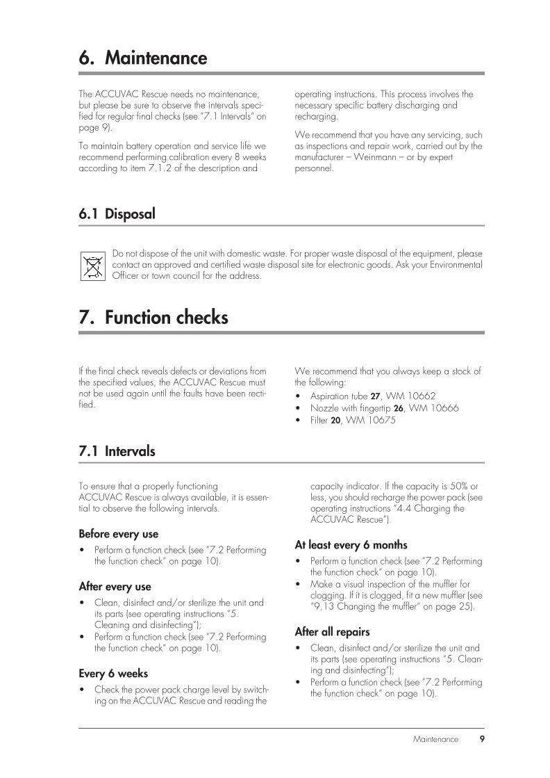
13.Connect the test pressure gage 0 to –1 bar to the fingertip.
14.Check the accuracy of all suction levels with the test pressure gage. Start at –0.05 bar. The tolerance of the individual suction levels must not exceed +/– 0.04 bar (5% of end value on scale).
15. Remove the test pressure gage from the fingertip.
16. Switch off the ACCUVAC Rescue.
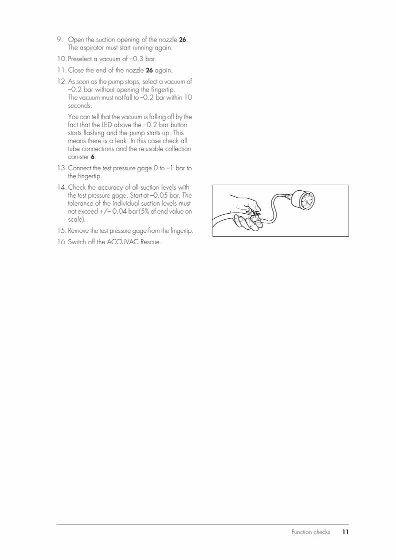
barO2-1,0
-0,8
-0,6 -0,4
-0,2
0
Function checks 11

8. TroubleshootingFa
ult
Caus
eLo
caliz
e fa
ult
Rem
edy
App
lianc
e do
es n
ot s
tart.
O/I
indi
cato
r and
ca
paci
ty in
dica
tor s
how
rea
dy fo
r ope
ratio
n
Vacu
um in
sys
tem
Det
ach
tube
from
pre
ssur
e se
nsor
. Sw
itch
appl
ianc
e of
f and
on
agai
n. P
ump
mus
t now
ru
n.
Cle
ar b
lock
age
in tu
be s
yste
m.
Con
trolle
r han
ging
.Pe
rform
rese
t.D
iscon
nect
ext
erna
l pow
er s
uppl
y an
d po
wer
pa
ck fr
om c
ircui
t boa
rd fo
r at l
east
2 m
inut
es.
Fron
t mem
bran
e fa
ulty
If di
spla
y te
st fu
nctio
ns o
n sw
itchi
ng o
n an
d th
e ap
prop
riate
set
val
ue L
ED fl
ashe
s w
hen
the
rele
vant
set
val
ue k
ey is
pre
ssed
, the
fron
t m
embr
ane
is in
ord
er. I
f not
, the
cau
se o
f the
fa
ult m
ay b
e ei
ther
the
front
mem
bran
e or
the
circ
uit b
oard
.
Firs
t che
ck th
e co
nnec
tion
betw
een
the
circ
uit
boar
d an
d th
e fro
nt m
embr
ane.
Oth
erw
ise fi
t ne
w fr
ont m
embr
ane.
Circ
uit b
oard
def
ectiv
eC
onne
ct c
ircui
t boa
rd to
func
tioni
ng p
ump
and
switc
h on
. If p
ump
does
not
run,
…
… fi
t new
circ
uit b
oard
(9.1
0, p
age
22)
Pum
p de
fect
ive
Con
nect
pum
p to
func
tioni
ng c
ircui
t boa
rd a
nd
switc
h on
. If p
ump
does
not
run,
…
… fi
t new
pum
p (9
.11,
pag
e 24
)
App
lianc
e do
es n
ot s
tart.
O/I
indi
cato
r doe
s no
t sho
w r
eady
for o
pera
tion
Con
trolle
r han
ging
Perfo
rm re
set
Disc
onne
ct e
xter
nal p
ower
sup
ply
and
pow
er
pack
from
circ
uit b
oard
for a
t lea
st 2
min
utes
.
Fuse
F1
or F
2 in
app
lianc
e de
fect
ive
If Re
scue
doe
s no
t cha
rge
up, f
use
F1 is
pr
obab
ly d
efec
tive.
Fit n
ew fu
se (9
.8, p
age
21)
Fuse
in v
ehic
le p
lug
defe
ctiv
eFi
t new
fuse
(9.1
2, p
age
25)
Pow
er p
ack
fully
disc
harg
edPe
rform
sev
eral
cha
rge/
disc
harg
e cy
cles
. If
unsu
cces
sful,
fit n
ew p
ower
pac
k (9
.6,
page
19)
Inco
rrect
pol
arity
of v
ehic
le p
ower
soc
ket
If an
ext
erna
l pow
er s
uppl
y w
ith in
corre
ct
pola
rity
is co
nnec
ted,
a p
rote
ctiv
e di
ode
ensu
res
that
fuse
F1
blow
s to
pro
tect
the
elec
troni
c sy
stem
.
Cor
rect
pol
arity
and
if n
eces
sary
repl
ace
fuse
F1
(9.8
, pag
e 21
)
Snap
-in c
onne
ctio
n be
twee
n ci
rcui
t boa
rd a
nd
pow
er p
ack
not p
rope
rly e
ngag
edM
ake
sure
con
nect
ion
snap
s in
12 Troubleshooting

App
lianc
e do
es n
ot re
ach
max
imum
vac
uum
of
–0.8
bar
in 2
0 se
cond
s, b
ut c
apac
ity in
dica
tor
show
s re
ady
for o
pera
tion
Leak
in s
uctio
n sid
e of
app
lianc
e
Disc
onne
ct s
ecre
tion
cont
aine
r fro
m p
ump
unit.
Sw
itch
on p
ump
and
run
at a
set
ting
of 0
.8 b
ar.
Hol
d th
umb
over
suc
tion
port.
The
max
imum
va
cuum
is re
ache
d w
ithin
5 s
ec. a
nd th
e pu
mp
stops
. If t
he p
ump
starts
up
agai
n w
ithin
10
to
20 s
ec.,
the
leak
is in
the
pum
p un
it.*
Che
ck th
at a
ll tu
bes
are
secu
rely
con
nect
ed a
nd
that
filte
r cov
er a
nd s
ecre
tion
cove
r are
firm
ly
insta
lled
Pow
er p
ack
not s
uffic
ient
ly c
harg
edC
onne
ct c
harg
er W
M 2
645.
If th
e pu
mp
now
ru
ns m
uch
mor
e “p
ower
fully
” th
an w
ith th
e po
wer
pac
k, y
ou m
ust …
… c
harg
e po
wer
pac
k (9
.6, p
age
19)
Filte
r clo
gged
Fit n
ew fi
lter
(ope
ratin
g in
struc
tions
5.3
)
Faul
t in
pum
pC
onne
ct p
ump
to fu
nctio
ning
circ
uit b
oard
and
sw
itch
on. I
f pum
p do
es n
ot ru
n …
… fi
t new
pum
p (9
.11,
pag
e 24
)
Muf
fler c
logg
edFi
t new
muf
fler
(9.1
3, p
age
25)
Pum
p ke
eps
on s
tarti
ng u
pLe
ak o
n su
ctio
n sid
e of
app
lianc
e.se
e ab
ove*
Not
cha
rgin
g
Exte
rnal
pow
er s
uppl
y to
o w
eak.
Che
ck s
ervi
ce d
ispla
y (2
.1, p
age
5). I
f the
x-
LED
ligh
ts up
, the
ext
erna
l pow
er s
uppl
y is
in
orde
r.
Exte
rnal
pow
er s
uppl
y m
ust b
e be
twee
n 12
.0
and
13.8
V.
Tem
pera
ture
of p
ower
pac
k to
o hi
gh.
N
o ch
argi
ng p
ossib
le a
bove
+40
° C
Che
ck s
ervi
ce d
ispla
y (2
.1, p
age
5). I
f the
0.3
ba
r LED
ligh
ts up
, the
pow
er p
ack
tem
pera
ture
is
not i
n th
e op
erat
ing
rang
e 5°
C to
45°
CA
llow
app
lianc
e to
coo
l bel
ow +
40°
C
Tem
pera
ture
of p
ower
pac
k to
o lo
w.
N
o ch
argi
ng p
ossib
le b
elow
+5°
C
Che
ck s
ervi
ce d
ispla
y (2
.1, p
age
5). I
f the
0.3
ba
r LED
ligh
ts up
, the
pow
er p
ack
tem
pera
ture
is
not i
n th
e op
erat
ing
rang
e 5°
C to
45°
CW
arm
app
lianc
e to
abo
ve +
5° C
Fuse
F1
or F
2 de
fect
ive
Che
ck s
ervi
ce d
ispla
y (2
.1, p
age
5). I
f the
0.2
ba
r LED
ligh
ts up
(pow
er p
ack
over
volta
ge),
fuse
F2
may
hav
e bl
own.
Fit n
ew fu
se (9
.8, p
age
21)
Fuse
in v
ehic
le p
lug
defe
ctiv
eFi
t new
fuse
(9.1
2, p
age
25)
Snap
-in c
onne
ctio
n be
twee
n po
wer
pac
k an
d ci
rcui
t boa
rd n
ot p
rope
rly e
ngag
ed
Che
ck s
ervi
ce d
ispla
y (2
.1, p
age
5). i
f the
0.2
ba
r LED
ligh
ts up
(pow
er p
ack
over
volta
ge),
the
conn
ecto
r to
the
pow
er p
ack
may
be
loos
e.
Mak
e su
re c
onne
ctio
n sn
aps
in (9
.9, p
age
21)
Faul
tCa
use
Loca
lize
faul
tRe
med
y
Troubleshooting 13

Gre
en 1
0% L
ED fl
ashi
ng.
Cap
acity
cou
nter
cle
ared
. Ch
argi
ng a
nd a
spira
tion
cont
inue
to w
ork
prop
erly
des
pite
this
mes
sage
Che
ck s
ervi
ce d
ispla
y. If
the
50%
LED
ligh
ts up
, th
e so
ftwar
e ha
s de
tect
ed a
n “u
nkno
wn”
pow
er
pack
. Thi
s ha
ppen
s w
hen
chan
ging
the
pow
er
pack
, fitti
ng a
new
fuse
F2,
and
som
etim
es if
po
wer
pac
k is
fully
disc
harg
ed, i
.e. w
hene
ver
the
pow
er p
ack
is di
scon
nect
ed fr
om th
e ci
rcui
t bo
ard.
The
sof
twar
e se
ts th
e ca
paci
ty c
ount
er to
0%
(red
LED
is o
n du
ring
pum
ping
and
ch
argi
ng) i
f it d
etec
ts a
pow
er p
ack
volta
ge o
f <1
0 V
durin
g pu
mp
oper
atio
n.
Initi
aliz
e (se
e ”9
.7 In
itial
izin
g th
e po
wer
pac
k“
on p
age
20)
100%
LED
doe
s no
t lig
ht u
p on
com
plet
ion
of
char
ging
Cha
rger
doe
s no
t mee
t spe
cific
atio
nsU
se m
ains
/ch
arge
r uni
t WM
264
5
Vehi
cle
elec
trica
l sys
tem
is n
ot s
uppl
ying
12.
0 –
13.8
V
Che
ck v
ehic
le e
lect
rical
sys
tem
Cap
acity
cou
nter
out
of a
djus
tmen
t
Che
ck se
rvic
e di
spla
y (2
.1, p
age
5). I
f the
30%
LE
D li
ghts
up, t
he p
ower
pac
k w
as fu
lly c
harg
ed
durin
g th
e la
st ch
argi
ng o
pera
tion.
Tip
: it m
ay
be th
at th
e ca
paci
ty c
ount
er is
on
99%
, with
the
resu
lt th
at th
e 10
0% L
ED d
oes
not l
ight
up.
Sw
itch
on p
ump
for a
ppro
x. 3
0 se
c. a
nd th
en
char
ge a
gain
. Afte
r a fe
w m
inut
es th
e 10
0%
LED
sho
uld
light
up.
If n
ot, t
he c
apac
ity c
ount
er
is co
mpl
etel
y ou
t of a
djus
tmen
t. In
that
cas
e yo
u m
ust …
… in
itial
ize
(see
”9.7
Initi
aliz
ing
the
pow
er
pack
“ on
pag
e 20
)
Pow
er p
ack
dam
aged
by
bein
g fu
lly
disc
harg
ed
Cha
rge
appl
ianc
e, s
witc
h on
and
set
to 0
.8
bar.
If th
e pu
mp
pow
er fa
lls o
ff af
ter a
few
m
inut
es, t
he p
ower
pac
k is
dam
aged
.Pe
rform
sev
eral
cha
rge/
disc
harg
e cy
cles
(o
pera
ting
instr
uctio
ns 4
.4, p
age
17).
If un
succ
essfu
l, fit
new
pow
er p
ack
(9.6
, pa
ge 1
9).
Pow
er p
ack
at e
nd o
f ser
vice
life
Che
ck s
ervi
ce d
ispla
y (2
.1, p
age
5). I
f the
0.2
ba
r LED
ligh
ts up
(pow
er p
ack
over
volta
ge),
the
inte
rnal
resis
tanc
e of
the
pow
er p
ack
may
be
very
hig
h du
e to
age
.
Faul
tCa
use
Loca
lize
faul
tRe
med
y
14 Troubleshooting

9. Repairs: Information and Instructions
9.1 General
An ESD workplace is essential for making repairs to the ACCUVAC Rescue.
No work should be performed on the appliance without a thorough knowledge of the Operating In-structions and the Service and Repair Instructions, which must always be complied with.
ACCUVAC Rescue is only intended for the pur-pose described (see ”3.1 Purpose“ on page 6).
When replacing components or individual parts, be sure to use only original Weinmann parts.
A function check (see ”7.2 Performing the function check“ on page 10) must be performed after every repair.
When ordering the rear part of the case, please state the appliance type, appliance number and year of manufacture.
9.2 Opening the device
Tools and equipment required:
• Phillips screwdriver size 2.
1. Switch off the ACCUVAC Rescue.
2. Disconnect the aspirator from the external power supply.
3. Remove the collection canister 28 and any accessories.
4. Unscrew the holder 29 for the collection canister.
5. Open the case by unscrewing the 6 cross-head screws 46. When opening the case, be careful not to damage the silicone sealing cord.
6. Carefully pull the front and rear case elements apart.
46
Repairs: Information and Instructions 15

9.3 Closing the device
Tools and equipment required:
• Phillips screwdriver size 2
1. Carefully put the front and rear case elements together again.
2. Screw the case together again, making sure that the silicone sealing cord is correctly inserted and is not jammed or otherwise damaged.
3. Perform a function check (see ”7.2 Performing the function check“ on page 10).
9.4 Replacing release catch
Tools and equipment required:
• Phillips screwdriver size 2;• Screwdriver, size 1;• Flat or pointed pliers.
1. Open the device (see ”9.2 Opening the de-vice“ on page 15).
2. Place the ACCUVAC Rescue on its front.
3. Push out retaining pins 63 from release catch 62 and remove them.
4. Remove the old or defective release catch 62. To do so, use a flat / blunt object to press down snap lock 65, which is located below release catch 62.
5. Take the new release catch 62 and insert it in the rear wall of the case.
6. Take O-ring 64 and locate it in the rear wall of the case between the loops of the release catch and the rear wall attachment point.
7. Take the retaining pins 63 and insert them in the bushing from outside to inside until you hear them click into place.
8. Close the device (see ”9.3 Closing the de-vice“ on page 16).
9. Perform a function check (see ”7.2 Performing the function check“ on page 10).
46
63
64
62
16 Repairs: Information and Instructions

9.5 Replacing membrane keyboard
Tools and equipment required:
• Phillips screwdriver size 1;• 7mm open-end wrench.
1. Open the device (see ”9.2 Opening the de-vice“ on page 15).
2. Carefully detach electrical power pack con-nector X3 from the circuit board.
3. Unscrew power pack holder (4 cross-head screws 40).
4. Remove power pack.
5. Carefully detach electrical connectors X1 and X2 of internal wiring harness from circuit board.
6. Carefully detach electrical connector X4 to motor from circuit board.
7. Carefully detach pressure measurement tube 47 from pressure sensor on circuit board.
8. Carefully open up cable grip of ribbon cable connector X5. Then carefully remove ribbon cable (do not touch the ribbon cable contacts with your fingers, as this can cause oxidation.)
9. Unscrew 4 retaining screws 46 from the circuit board. Remove the circuit board.
10.Detach the front keyboard 4 from inside through the front of the case, by pressing the membrane keyboard out upwards and careful-ly pulling it off.
11.Clean the old adhesive area until no adhesive residues are left.
12. Take the new membrane keyboard and re-move the protective layer from the adhesive surface. Run the ribbon cable through the opening in the case front. Take care when inserting the ribbon cable through the opening in the housing; it must be properly routed without any kinks.
13.Stick the new membrane keyboard in the cor-rect position on the case.
40X3
X4 X2 X147
X5
X4 46
Repairs: Information and Instructions 17

14. Pull the protective film off the new membrane keyboard.
15. Insert the circuit board again and screw it up firmly.
16.Carefully restore electrical connections X1, X4 and X5.
17.Carefully attach electrical connector X2.
18. Fit tube 47 onto the board again.
19. Insert the power pack again and screw it firmly in place.
20.Make the electrical connection X3 to the pow-er pack.
21.Close the device (see ”9.3 Closing the de-vice“ on page 16).
22. Perform initialization (see ”9.7 Initializing the power pack“ on page 20).
23. Perform a function check (see ”7.2 Performing the function check“ on page 10).
X5
X4 46X1
X247
40X3
18 Repairs: Information and Instructions

9.6 Changing the power pack
The ACCUVAC Rescue is fitted with a high-grade nickel-cadmium power pack.
Tools and equipment required:
• Phillips screwdriver size 2.
1. Open the device (see ”9.2 Opening the de-vice“ on page 15).
2. Carefully disconnect the power pack connec-tor X3 from the circuit board.
3. Unscrew the power pack holder (4 cross-head screws).
4. Remove the faulty power pack 16.
Help protect the environment!
Don’t throw the old power pack in the gar-bage can – take it to a local collection point for environment-friendly disposal.
5. Wait half a minute before fitting the new power pack. This will allow the capacitors on the circuit board to discharge.
6. Fit the new power pack with its holder.
7. Carefully push power pack connector X3 onto the circuit board until it snaps into place.
8. Close the device (see ”9.3 Closing the de-vice“ on page 16).
9. Perform initialization (see ”9.7 Initializing the power pack“ on page 20).
Note:The green 10% LED of the capacity indicator 3 continues to flash until the electronic control system is synchronized with the power pack. Although the ACCUVAC Rescue will function when the power pack is charged, the indicator will not show the charge status of the power pack unless the system is initialized.
10. Perform a function check (see ”7.2 Performing the function check“ on page 10).
X3
Repairs: Information and Instructions 19
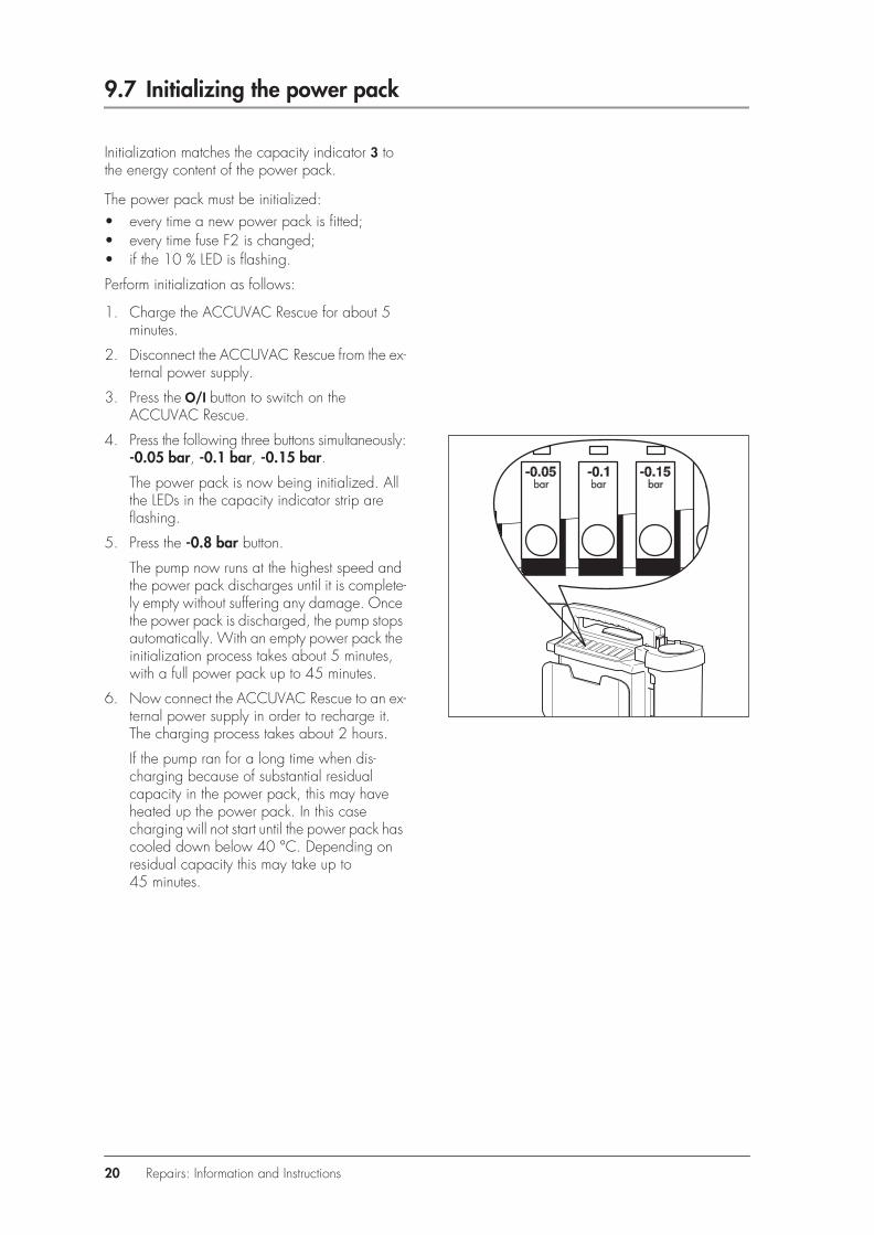
9.7 Initializing the power pack
Initialization matches the capacity indicator 3 to the energy content of the power pack.
The power pack must be initialized:• every time a new power pack is fitted;• every time fuse F2 is changed;• if the 10 % LED is flashing.
Perform initialization as follows:
1. Charge the ACCUVAC Rescue for about 5 minutes.
2. Disconnect the ACCUVAC Rescue from the ex-ternal power supply.
3. Press the O/I button to switch on the ACCUVAC Rescue.
4. Press the following three buttons simultaneously: -0.05 bar, -0.1 bar, -0.15 bar.
The power pack is now being initialized. All the LEDs in the capacity indicator strip are flashing.
5. Press the -0.8 bar button.
The pump now runs at the highest speed and the power pack discharges until it is complete-ly empty without suffering any damage. Once the power pack is discharged, the pump stops automatically. With an empty power pack the initialization process takes about 5 minutes, with a full power pack up to 45 minutes.
6. Now connect the ACCUVAC Rescue to an ex-ternal power supply in order to recharge it. The charging process takes about 2 hours.
If the pump ran for a long time when dis-charging because of substantial residual capacity in the power pack, this may have heated up the power pack. In this case charging will not start until the power pack has cooled down below 40 °C. Depending on residual capacity this may take up to 45 minutes.
20 Repairs: Information and Instructions

9.8 Changing fuse F1 or F2
ImportantNever touch the circuit board, as this can damage the electronic system.
Tools and equipment required:
• Phillips screwdriver size 2.
1. Open the device (see ”9.2 Opening the de-vice“ on page 15).
2. Remove the faulty fuse 14/15. The fuses are identified on the circuit board.
3. Insert a new fuse. Always use approved fuses (see ”13. Technical Data“ on page 30).
4. Close the device (see ”9.3 Closing the de-vice“ on page 16).
5. Perform initialization if you have removed fuse 15 (F2) from its holder (see ”9.7 Initializing the power pack“ on page 20).
6. Perform a function check (see ”7.2 Performing the function check“ on page 10).
9.9 Checking connector between circuit board and power pack
Tools and equipment required:
• Phillips screwdriver size 2.
1. Open the device (see ”9.2 Opening the de-vice“ on page 15).
2. Check connector X3.
3. Close the device (see ”9.3 Closing the de-vice“ on page 16).
4. Perform initialization (see ”9.7 Initializing the power pack“ on page 20).
5. Perform a function check (see ”7.2 Performing the function check“ on page 10).
14 15
X3
Repairs: Information and Instructions 21

9.10 Fitting new circuit board WM 10680
Important!For this operation it is essential to use an ESD work-place because of the risk of damage to the circuit board by static electricity.
Tools and equipment required:
• Phillips screwdriver size 2.
1. Open the device (see ”9.2 Opening the de-vice“ on page 15).
2. Carefully detach electrical power pack con-nector X3 from the circuit board.
3. Unscrew power pack holder (4 cross-head screws 40).
4. Remove power pack.
5. Carefully detach electrical connectors X1 and X2 of internal wiring harness from circuit board.
6. Carefully detach electrical connector X4 to motor from circuit board.
7. Carefully detach pressure measurement tube 47 from pressure sensor on circuit board.
X4 X2 X1 X3
40X3
X4 X2 X147
22 Repairs: Information and Instructions

8. Carefully open up cable grip of ribbon cable connector X5. Then carefully remove ribbon cable (do not touch the ribbon cable contacts with your fingers, as this can cause oxidation.)
9. Unscrew 4 retaining screws 46 from the circuit board.
10. Insert the new circuit board in reverse order. Then route connecting cable so it cannot come into contact with the pump.
• Attention! Do not connect electrical power pack connector X3 yet.
• Wait half a minute to allow the capacitors on the circuit board to discharge.
11.Carefully connect electrical power pack connector X3.
12.Close the device (see ”9.3 Closing the de-vice“ on page 16).
13. Perform initialization (see ”9.7 Initializing the power pack“ on page 20).
The green 10% LED of the capacity indicator con-tinues flashing until the electronic control system has been synchronized with the power pack. Although the fully charged ACCUVAC Rescue can be used, the power pack charge status is not dis-played.
14. Perform a function check (see ”7.2 Performing the function check“ on page 10).
X5
X4 46
X3
Repairs: Information and Instructions 23
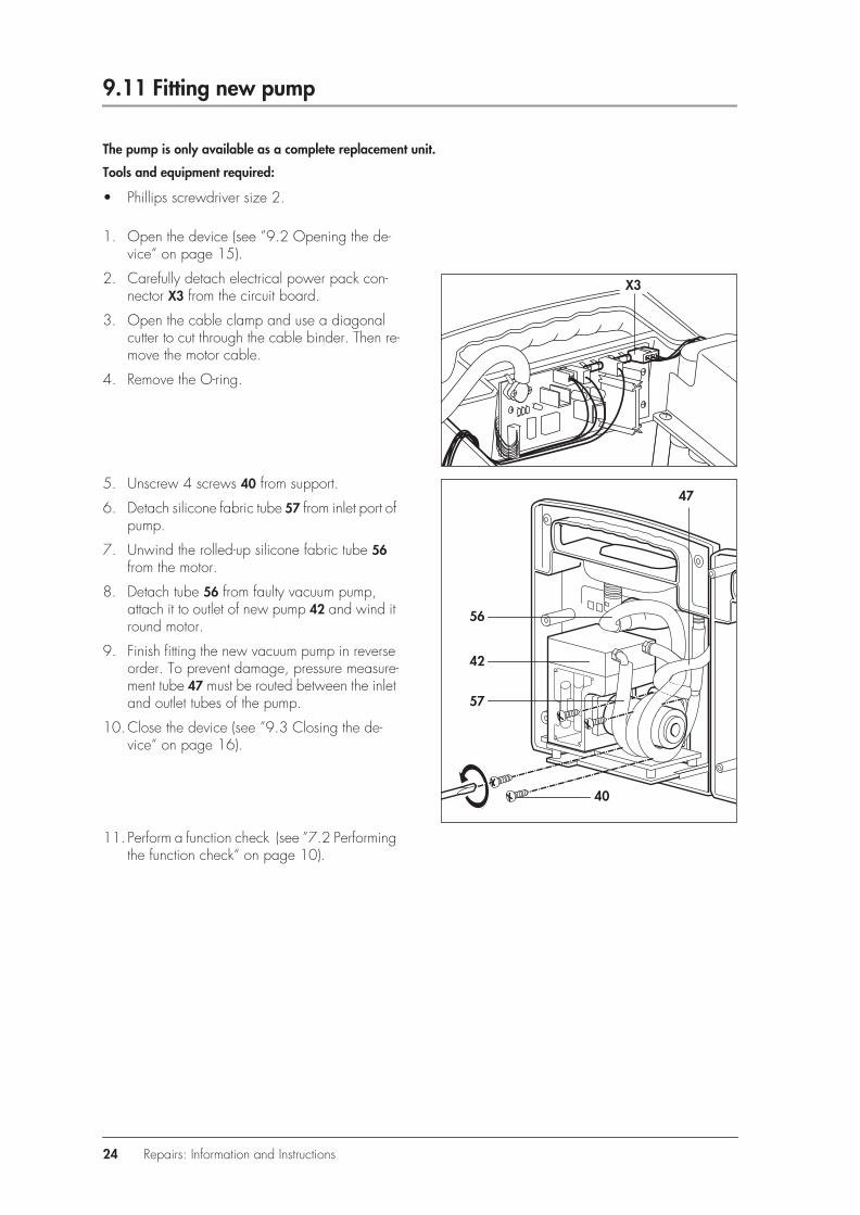
9.11 Fitting new pump
The pump is only available as a complete replacement unit.
Tools and equipment required:
• Phillips screwdriver size 2.
1. Open the device (see ”9.2 Opening the de-vice“ on page 15).
2. Carefully detach electrical power pack con-nector X3 from the circuit board.
3. Open the cable clamp and use a diagonal cutter to cut through the cable binder. Then re-move the motor cable.
4. Remove the O-ring.
5. Unscrew 4 screws 40 from support.
6. Detach silicone fabric tube 57 from inlet port of pump.
7. Unwind the rolled-up silicone fabric tube 56 from the motor.
8. Detach tube 56 from faulty vacuum pump, attach it to outlet of new pump 42 and wind it round motor.
9. Finish fitting the new vacuum pump in reverse order. To prevent damage, pressure measure-ment tube 47 must be routed between the inlet and outlet tubes of the pump.
10.Close the device (see ”9.3 Closing the de-vice“ on page 16).
11. Perform a function check (see ”7.2 Performing the function check“ on page 10).
X3
56
57
40
42
47
24 Repairs: Information and Instructions

9.12 Changing fuse in vehicle plug
Tools and equipment required:
• Phillips screwdriver size 2.
1. Use a screwdriver to open the vehicle plug.
Note: The central contact of the plug is the plus pole. The plus lead of the cable has either a square cross-section or colored markings. The outer contact of the plug is the minus pole. The minus lead of the cable is round and black.
2. Change the faulty fuse 58. Use only approved fuses (see ”13. Technical Data“ on page 30).
3. Screw the vehicle plug together again.
4. Perform a function check (see ”7.2 Performing the function check“ on page 10).
9.13 Changing the muffler
Tools and equipment required:
• Phillips screwdriver size 2.
1. Use a screwdriver to unscrew the cover plate (2 cross-head screws 41).
2. Remove the old muffler 12.
3. Insert a new muffler 12.
58
41
12
Repairs: Information and Instructions 25

4. Refit the cover plate 59.
Note that there is a projecting lug on the back of the cover plate. Be sure to fit the cover plate so that this lug locates the muffler in position.
5. Perform a function check (see ”7.2 Performing the function check“ on page 10).
9.14 Electrical circuit diagram
projecting lug
59
Power pack, NiCadWM 10647
+
-
X1
X2
red
black
Membrane keypad,Rescue
Vacuum pumpWM 10694 Pr
inte
d ci
rcui
t boa
rdA
ccuv
ac R
escu
eW
M 1
0680
X1
X2
X3
X4
X5
red
black
Char
ging
/ope
ratin
g co
ntac
ts
26 Repairs: Information and Instructions

10. Spare Parts
10.1 Spare parts list
Note:
The item numbers in the following table are identical with the numbers used in these Service and Repair Instructions and the Operating Instructions.
Item No. Spare Part Order No.
4 Membrane keyboard ACCUVAC Rescue WM 10645
6
192022232425262728
Re-usable canister, complete consisting of:– Filter cover– Bacteria filter– Bracing clip– Secretion cover– Ball– Sealing ring– Nozzle with fingertip– Aspiration tube– Collection canister 900 ml
WM 10630
WM 10632WM 10675WM 10641WM 10636WM 10643WM 10635WM 10666WM 10662WM 10631
8 Tube holder plate, red WM 10623
12 Muffler WM 10665
14 Fuse, external power supply (F1) WM 2692
15 Fuse, power pack (F2) WM 2692
16 NiCad power pack WM 10647
29
Holder set for re-usable canisterconsisting of:– Holder– Fixing elements
WM 15271
WM 10640WM 53053
30
3633313534
Set, disposable bag container, complete consisting of:– disposable bag container, complete – Collection canister – Disposable bag – Aspiration tube with nozzle and fingertip– T-piece – Vacuum tube
WM 15268
WM 10730WM 10731WM 10732WM 10733WM 10738WM 10740
37 Holder setconsisting of:– Holder– Fixing elements
WM 15172
WM 10735WM 51091
38 Front case element, Rescue, assembled, reconditioned* WM 10606
39 Rear case element, Rescue, assembled, reconditioned* WM 10607
40 Oval head screw KB 40x14 WM 23158
41 Countersunk screw KB 40x12 WM 58360
42 Vacuum pump, complete (new)* WM 10694
Spare Parts 27

* When ordering, please state type, appliance no. and year of manufacture
43 Vacuum pump, complete (exchange unit)* WM 10605
44 PCB Rescue WM 10680
45 PCB Rescue, exchange unit WM 10604
46 Oval head screw M3x14 WM 53032
47 Pressure measurement tubeconsisting of:– Tube, silicone fabric 3x3; 220 mm long– Tube nozzle
WM 10661
WM 10761WM 10658
48 Washer DIN 125 WM 50235
49 Spring washer DIN 127 WM 50350
50 Internal wiring harness, Rescue WM 10686
51 Oval head screw for clip, KB 35x8 WM 58350
52 Washer 4.3 DIN 125 WM 50240
53 Tube, silicone 7x2.5; 690 mm long WM 10668
54
55 56 57
Tube system, internalconsisting of:– T reducer 8-4-8– Tube, silicone fabric 8x3.5; 210 mm long– Tube, silicone fabric 8x3.5; 70 mm long
WM 10660
WM 10663WM 10669WM 10664
58 Fuse, vehicle plug WM 10673
59 Cover plate, red WM 10625
60 Round cord 930 mm long WM 10612
61 Cable tie WM 4668
5
62 63 64 65
Set release catch, redconsisting of:– Release catch, red *– Retaining pin– O-ring 2.9 x 1.78– Snap lock
WM 15396
WM 10624WM 10697WM 1145/80WM 10627
Tube, silicone fabric 6x3.5; 50 mm longTube, silicone fabric 6x3.5; 200 mm long
WM 10766WM 10765
Operating instructions WM 16136
Item No. Spare Part Order No.
28 Spare Parts

Tools and Test Equipment 29
11. Tools and Test Equipment
Following is a list of tools and test equipment men-tioned in these Service and Repair Instructions.
See the relevant chapter for details of the tools and test equipment needed in each case.
Special tools can be obtained from the manufacturer, Weinmann.• Cross-head screwdriver, size 1• Cross-head screwdriver, size 2• Pliers• Vacuum test pressure gage set WM 15294
12. Technical Changes
Technical change From Device No. Date
Reinforced release catch 2117 09.11.98
Software update Version 3.0 4500 22.08.00
New holder for release catch 6730 16.07.01
Case reinforced, use of washers discontinued 8105 20.11.01
Printed circuit board with radio suppression 9145 07.06.02
Vacuum pump without side walls 10048 22.10.02
Appliance plate with e1 mark 13445 28.06.04

13. Technical Data
ACCUVAC Rescue
Product category according to 93/42/EEC II b
DimensionsWxHxD in mm 370x280x140
Weight approx. 5.1 kg
Canister volume 900 ml
Suction capacity at 12 V with free flow > 20 l/min
Max. vacuum at 12 V 0.8 bar (80 kPa)
Aspiration tube diam. 10 mm, length 1300 mm
Hydrophobic bacteria filtersize rating 1 µm, water breakthrough pressure 0.3 bar
Motor output 50 W
Rated voltage 12 V
Maximum current consumption 3.5 A
Temperature rangeOperationChargingStorage
–18 °C to +40 °C+ 5 °C to +40 °C–40 °C to +70 °C
Electromagnetic compatibility:Radio interference suppressionRadio interference resistance
EN60601-1-2
EN 55011 IEC 1000-4 Parts 2–5 & 11
Classification according to EN 60601-1:Protection against electric shock: class II; with charger: class IDegree of protection against electric shock: BFDegree of protection against water: IPX 1 (drip water)
Classification according to EN ISO 10079-1 high vacuum/high flow
(Subject to technical change without notice)
Norms complied with EN 60601-1, EN ISO 10079-1, EN 1789
Vehicle plug fuse 8 A, DIN 72581, identification color white
Internal fuse F1 external power supply
4 A slow-acting,low breaking capacityG fuse links 5x20 mm,conforms to IEC 127
Internal fuse F2 power pack
4 A slow-acting, low breaking capacityG fuse links 5x20 mm,conforms to IEC 127
Power pack type Nickel cadmium 2.8 Ah
Charging voltage 12.0 to 13.8 V
Operating time after charging for 2 hours 45 min at maximum suction
Operating mode S2 60 min
Service life of power pack 400 charge/discharge cycles in approx. 3 years
Materials
Collection canister APEC
Secretion cover Silicone
Ball PVDF
Filter cover Silicone
Filter holder APEC
ACCUVAC Rescue
From serial no. 13445/2004
30 Technical Data
13.1 Safe distances
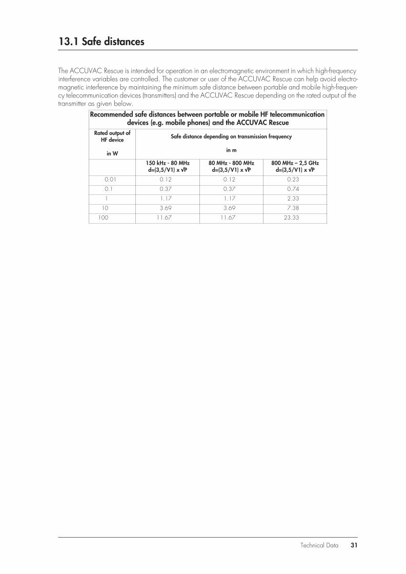
The ACCUVAC Rescue is intended for operation in an electromagnetic environment in which high-frequency interference variables are controlled. The customer or user of the ACCUVAC Rescue can help avoid electro-magnetic interference by maintaining the minimum safe distance between portable and mobile high-frequen-cy telecommunication devices (transmitters) and the ACCUVAC Rescue depending on the rated output of the transmitter as given below.
Recommended safe distances between portable or mobile HF telecommunication devices (e.g. mobile phones) and the ACCUVAC Rescue
Rated output of HF device
in W
Safe distance depending on transmission frequency
in m
150 kHz - 80 MHzd=(3,5/V1) x √√√√P
80 MHz - 800 MHzd=(3,5/V1) x √√√√P
800 MHz – 2,5 GHzd=(3,5/V1) x √√√√P
0.01 0.12 0.12 0.23
0.1 0.37 0.37 0.74
1 1.17 1.17 2.33
10 3.69 3.69 7.38
100 11.67 11.67 23.33
Technical Data 31

32 Repair and Test Report
14. Repair and Test Report
Keep a record of all tests or repairs performed (please copy attached form for use).D
evic
e m
aste
r da
taM
aint
enan
ce a
nd r
epai
r w
ork
carr
ied
out i
n ac
cord
ance
with
ser
vice
doc
umen
t
Man
ufac
ture
rs:
Wei
nman
n G
mbH
+ C
o.22
525
Ham
burg
mai
nten
ance
/ re
pair
/ c
omm
ents
Serv
ice
perfo
rmed
in
acco
rdan
ce w
ith A
CC
UVA
C-
Serv
ice
and
Repa
ir In
struc
tions
Com
pany
____
____
___
____
____
____
____
Dat
eSi
gnat
ure
Dev
ice
mod
e:A
CCU
VA
C
WM
106
00 A
CC
UVA
C R
escu
e
WM
107
00 A
CC
UVA
C R
escu
e
Dev
ice
no.:
____
____
____
____
____
___
Com
pany
____
____
___
____
____
____
____
Dat
eSi
gnat
ure
Prod
uctio
n da
te: _
____
____
____
____
__
Com
pany
____
____
___
____
____
____
____
Dat
eSi
gnat
ure
Com
pany
____
____
___
____
____
____
____
Dat
eSi
gnat
ure


WM
162
93b
- 07/
06 ·
Prin
ted
on 1
00%
recy
cled
pap
er
Weinmann
Geräte für Medizin GmbH + Co. KG
P.O. Box 540268 · D-22502 Hamburg
Phone +49/40/5 47 02-0
Fax +49/40/5 47 02-461
E-mail [email protected]
Internet www.weinmann.de
For decades Weinmann has been
developing, producing and marketing
medical devices for markets around
the world. In cooperation with our
partners we design economic health
systems for diagnosis and therapy in
Sleep Medicine, Home Mechanical
Ventilation, Oxygen Medicine
and Emergency Medicine.