Embed Size (px)
Citation preview

A presentation of theA presentation of theConcrete Reinforcing Steel InstituteConcrete Reinforcing Steel Institute

• What “materials” are used to make rebar?
b d ?• How is rebar made?
• How is rebar used?• How is rebar used?
• ASTM Specsp
• Typical framing systems


Today’s Reinforcing Steel is 100% Recycledy


16
17
18


•• CouplersCouplers•• CouplersCouplers
•• End AnchorsEnd AnchorsEnd AnchorsEnd Anchors
•• Corrosion ProtectionCorrosion Protection
•• High Strength Reinforcing Grade 100 & 120High Strength Reinforcing Grade 100 & 120


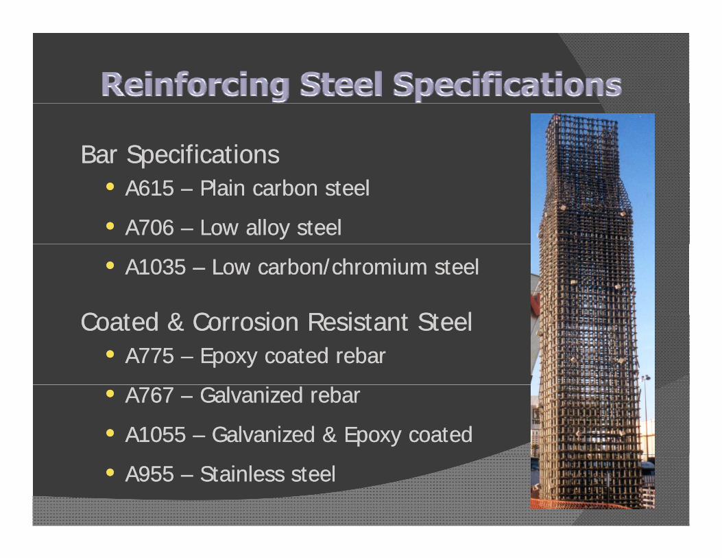
Bar SpecificationsBar Specifications•• A615 A615 –– Plain carbon steelPlain carbon steel
•• A706 A706 –– Low alloy steelLow alloy steel
•• A1035 A1035 –– Low carbon/chromium steelLow carbon/chromium steel
C t d & C i R i t t St lC t d & C i R i t t St lCoated & Corrosion Resistant SteelCoated & Corrosion Resistant Steel•• A775 A775 –– Epoxy coated rebarEpoxy coated rebar
•• A767 A767 –– Galvanized rebarGalvanized rebar
•• A1055 A1055 –– Galvanized & Epoxy coatedGalvanized & Epoxy coated
•• A955 A955 –– Stainless steelStainless steel

Metrification ……… or not ?Metrification ……… or not ?
•• ASTM Specifications in inchASTM Specifications in inch--pound unitspound units•• Soft SI conversations are shown for referenceSoft SI conversations are shown for reference•• Soft SI conversations are shown for referenceSoft SI conversations are shown for reference
•• Majority of reinforcing steel marked in soft SIMajority of reinforcing steel marked in soft SI
•• Industry talks in inchIndustry talks in inch--pound unitspound units
•• Design community works in inchDesign community works in inch--pound unitspound units
•• Construction is performed in inchConstruction is performed in inch--pound unitspound unitsConstruction is performed in inchConstruction is performed in inch pound unitspound units

What is bar size?What is bar size?•• InchInch--pound bar size designations represent pound bar size designations represent
1/8” inch fractions1/8” inch fractions
Inch-Pound Units SI UnitsBar Designation Nominal Diameter Bar Designation Nominal DiameterBar Designation Nominal Diameter Bar Designation Nominal Diameter
#3 3/8” #10 9.5 mm#4 4/8” #13 12.7 mm#5 5/8” #16 15 9 mm#5 5/8 #16 15.9 mm#6 6/8” #19 19.1 mm#7 7/8” #22 22.2 mm#8 8/8” #25 25 4 mm#8 8/8 #25 25.4 mm
…… #9, 10, 11, 14, 18

ASTM A615 Grade 40 (Grade 280)
Grade 60 (Grade 420)
Grade 75 (Grade 520)(Grade 280) (Grade 420) (Grade 520)
Minimum Yield Strength, psi (MPa)
40,000 (280)
60,000 (420)
75,000 (520)
Minimum Tensile 60 000 90 000 100 000Minimum Tensile Strength, psi (MPa)
60,000 (420)
90,000 (620)
100,000 (690)
Bar Designation Minimum Percent Elongation in 8”
#3 11 9 7
#4, #5 12 9 7
#6 12 9 7#6 12 9 7
#7, #8 - 8 7
#9, #10, #11 - 7 6
#14, #18 - 7 6

ASTM A706 Grade 60 (Grade 420)
Grade 80 (Grade 555)(Grade 420) (Grade 555)
Minimum Yield Strength, psi (MPa)
60,000 (420)
80,000 (555)
Maximum Yield 78 000 100 000Maximum Yield Strength, psi (MPa)
78,000 (540)
100,000 (690)
Minimum Tensile Strength psi (MPa)
80,000* (550)
105,000* (725)Strength, psi (MPa) (550) (725)
* Tensile strength shall not be less than 1.25 times the actual yield strength
Bar Designation Minimum Percent Elongation in 8”
#3, #4, #5, #6 14 12
#7, #8, #9, #10, #11 12 12
#14, #18 10 10

• Tensile Requirements
• Bending Requirements• Withstand bending without cracking
• Permissible Variation in Weight• At least 94% of nominal weight
• Deformations• Orientation, size, spacing, height
M ki• Marking• Mill, bar size, type, grade
Fi i h• Finish


• Material Specifications for Reinforcing BarsReinforcing Bars
• Welded Wire Fabric (WWF)
• Bar Supports
• Notes to Architects/Engineers
• Estimating Reinforcing Materials
• Detailing Reinforcing Materials
• Fabrication of Reinforcing Materials
Pl i R i f i B• Placing Reinforcing Bars
• Contract Components
• Concrete Joist Construction• Concrete Joist Construction
• APPENDICESFirst published - 1927


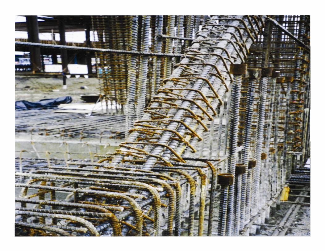
• Tying does not add to the strength of the finished structure
• Specifications typically require that a• Specifications typically require that a specified number of intersections by tied
• Criteria for tying:
“Th t b ill t“The mats, cages, or bars will not displace during casting, screeding,
d fi i hi ti ”and finishing operations”

CRSI Manual of Standard PracticeCRSI Manual of Standard Practice- Section 8.3
“At the time of placement, all reinforcing
bars shall be free of mud, oil, or other
d l i i l ”deleterious materials.”


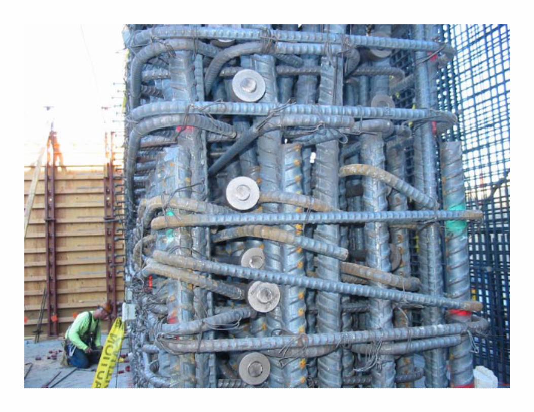
BEAM-COLUMN JOINTBEAM COLUMN JOINT

HEADED BARSHEADED BARS
40

PUNCHING SHEAR STUDSPUNCHING SHEAR STUDS
41
ion
urat
onfig
al C
oFi
na
42
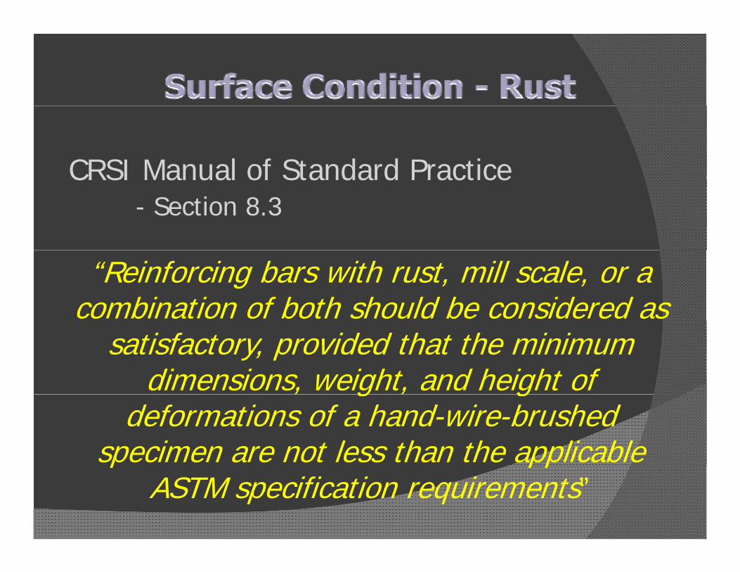
CRSI Manual of Standard PracticeCRSI Manual of Standard Practice- Section 8.3
“Reinforcing bars with rust, mill scale, or a combination of both should be considered as
satisfactory, provided that the minimum dimensions, weight, and height of , g , g
deformations of a hand-wire-brushed specimen are not less than the applicable p pp
ASTM specification requirements”

• To correct bars partially embedded in concrete due to incorrect fabrication, incorrect placement, accidental misalignment or design change
• Not field fabrication• Not field fabrication
• In-situ bending is prohibited unlessIn situ bending is prohibited unless shown on drawings or specifically authorized by the engineerauthorized by the engineer

• Limited to bar size #11 and smaller
• Bend diameters must conform to ACI 318
• Bar sizes #3 through #5 and if wereBar sizes #3 through #5 and if were previously unbent, can be bent cold
• Ba si es #3 th o gh #5 and if e e• Bar sizes #3 through #5 and if were previously bent, must be heated prior to straightening and re-bendingstraightening and re bending
• Bar sizes #6 through #11 must be heated prior to straightening and/or bendingprior to straightening and/or bending

Bending Condition Bar Size
Reduction in Yield
Strength
Reduction in Ultimate
Tensile St th
Reduction in ElongationStrength Strength
#3 & #4 - - 20%Cold
#5 5% - 30%
Hot All Sizes 10% 10% 20%
S CSource: Concrete International January 1992 - Khossrow Babaei and Neil M. Hawkins

Bar Size Minimum Temperature
Maximum Temperature
#3 & #4 1,200 F 1,250 F
#5 & #6 1,350 F 1,400 F, ,
#7, #8 & #9 1,400 F 1,450 F
#10 & #11 1,450 F 1,500 F
S CSource: Concrete International January 1992 - Khossrow Babaei and Neil M. Hawkins
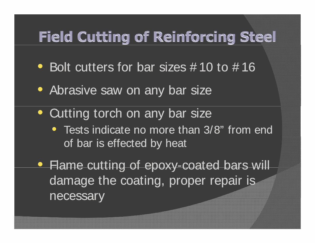
•• Bolt cutters for bar sizes #10 to #16Bolt cutters for bar sizes #10 to #16
•• Abrasive saw on any bar sizeAbrasive saw on any bar size
•• Cutting torch on any bar sizeCutting torch on any bar size•• Tests indicate no more than 3/8” from end Tests indicate no more than 3/8” from end
of bar is effected by heatof bar is effected by heat
•• Flame cutting of epoxyFlame cutting of epoxy--coated bars willcoated bars willFlame cutting of epoxyFlame cutting of epoxy coated bars will coated bars will damage the coating, proper repair is damage the coating, proper repair is necessarynecessarynecessarynecessary

•• Nylon Nylon slings or other padded material to slings or other padded material to lift barslift bars
•• Lift and set bars intoLift and set bars into placeplaceLift and set bars into Lift and set bars into placeplace•• Bars are not to be dragged into placeBars are not to be dragged into place
•• Minimize walking on barsMinimize walking on bars•• Set up a walkwaySet up a walkway
•• Bars to be visually inspected for damage Bars to be visually inspected for damage after placementafter placementafter placementafter placement


• Lap Splices
• Welded Splices
• Mechanical Splices• Deformation Dependentp• Non-Deformation Dependent

• Bolted

Bolt heads shear off when proper values are reached
Gripping

• Tapered Thread


• Efficiency in design and construction
• New tools and techniques
58

59

60

• Formwork
• Concrete
• Reinforcement


Minimizing material quantities can lead to “inefficient” designs

Designing to
i i i titiminimize quantities
of concrete and
reinforcement leads
to false economyto false economy

Optimizing design and utilization of
formwork holds theformwork holds the
key to true economy

Keep FormworkKeep Formwork
1. Simple
2. Repetitious
3. Standard• Form sizes• Lumber dimensions

M t i l i d t ff t f i tMaterial savings does not offset forming costs

• Make column same sizeMake column same size throughout• Vary concrete strengthy g• Vary percentage of
reinforcement
• Use fewer, larger bars
• Utilize mechanical couplersUtilize mechanical couplers
• Consider Grade 75 (Grade 80)
i f treinforcement

• Space columns uniformlySpace columns uniformly
• Use fewest column sizes
• When column size must change, reduce one dimension at a time


M k b idMake beams wider than columns
Size beams and joists the same
depth
• Select one floor framing systemSelect one floor framing system
• Use shallowest system
• For most buildings floor framing costs dominate
• Vertical element costs become more significant in taller buildings or insignificant in taller buildings or in moderate to strong seismic zones
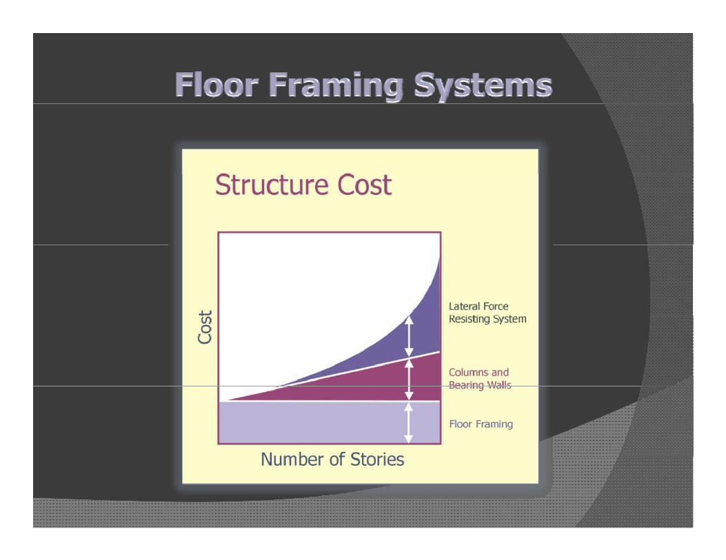
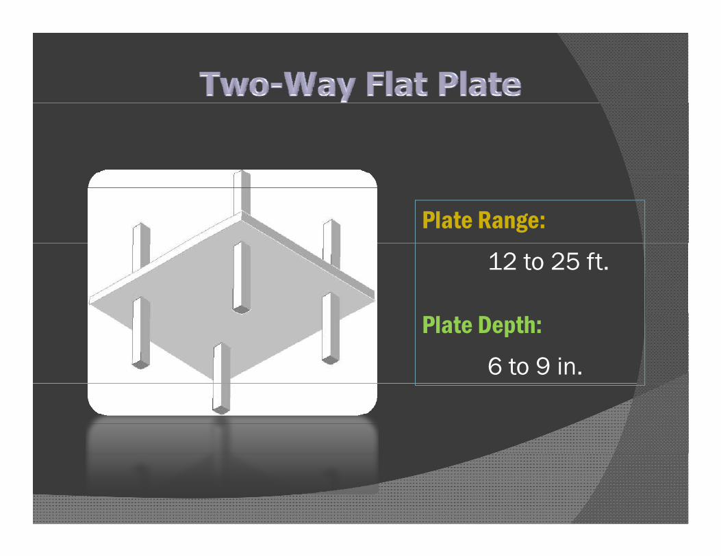
Plate Range:12 to 25 ft.
Plate Depth:6 to 9 in.
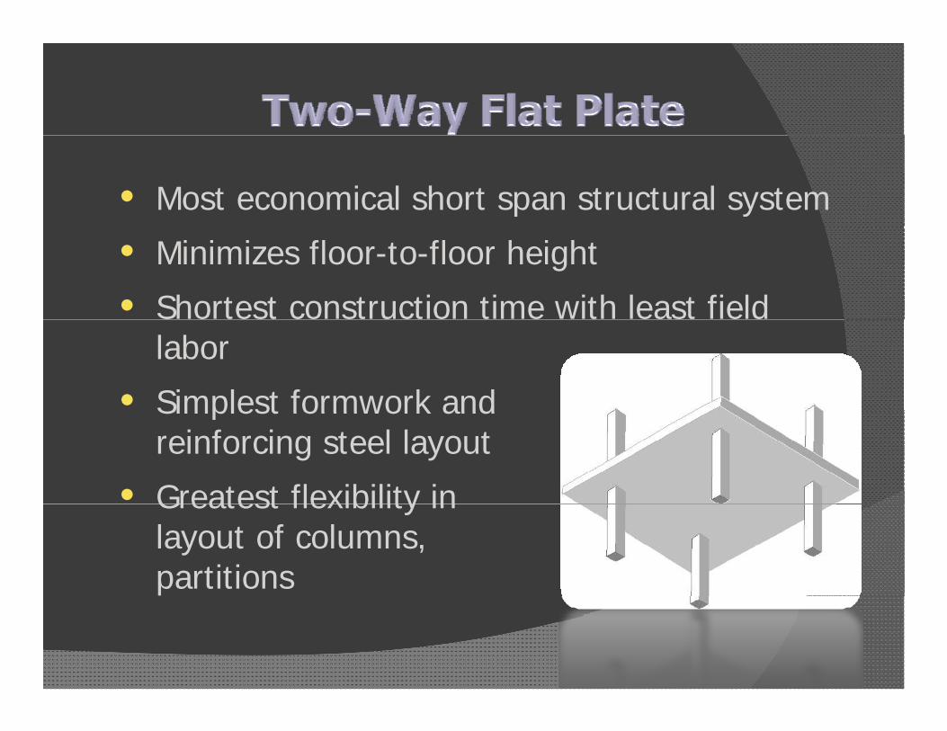
• Most economical short span structural system
• Minimizes floor-to-floor height
• Shortest construction time with least field labor
• Simplest formwork andSimplest formwork and reinforcing steel layout
• Greatest flexibility inGreatest flexibility in layout of columns, partitions

Plate Range:20 to 35 ft.
Plate Depth:7 to 12 in.

• Very economical system for relatively square b d lti l b i h di tibays and multiple bays in each direction
• Uses smaller columns than Two-Way Flat Plate h lwith longer spans
• Provides uniform clear space below slab
• Provides flexibility in layout of columns, partitions
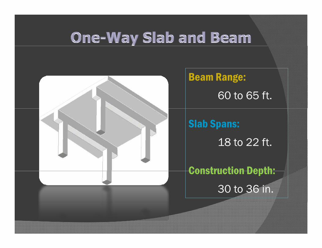
Beam Range:Beam Range:60 to 65 ft.
Slab Spans:18 t 22 ft18 to 22 ft.
Construction Depth:Construction Depth:30 to 36 in.

• Good for concentrated and heavy load areas
• Basis for more complex framing systems
• Commonly used for parking structures and y p gelevator and stair areas
• Excellent vibrationExcellent vibration characteristics
• Popular for use inPopular for use in commercial buildings
• Adaptable to custom• Adaptable to custom forming situations

Beam Range:Beam Range:Up to 30 ft.
Joist Spacing:24 t 36 i24 to 36 in.
Pan Depth:Pan Depth:8 to 20 in.

• Provides depth for stiffness and increased load b i itbearing capacity
• Efficient use of concrete and reinforcing lmaterials
• Standard reusable forms readily removed and re-erected
• Accommodates floor penetrations and mechanical systemsmechanical systems


• Life cycle cost, not project or initial cost
• Contribution of concrete to other systemssystems
• Sustainability and concrete constructiony
• Scalable, adaptable and expandable to d t f t daccommodate future needs

• Readily available materials
• Local materials
• Staging and transportation logistics areStaging and transportation logistics are minimal

• On-site adaptability
• Multi-track construction
• Concrete inherenciesConcrete inherencies
• Concurrent work due to concrete inherenciesinherencies
• Multiple trades working off the critical path
• Jobsite safety is the key

• Cash flow is back-end loaded
• Local materials
• Reduced lead timesReduced lead times
• Minimal staging

• Building for space, not volume
• Height restrictions
• Urban footprintUrban footprint
• Reduction in vertical material utilization and costs

• Reduced HVAC costs
• Low maintenance costs
• Lower insurance premiumsLower insurance premiums
• More than just initial frame cost
• Elimination of material and labor expenses
• Cost and time savingsCost and time savings

• Limited fluctuations in temperature
• Savings in energy and cost

• Concrete is non combustible
• No fireproofing required
• Connections are protectedConnections are protected
• Reduced insurance premiums

• Vibration and heat sensitive equipment
• Research Labs
• HospitalsHospitals
• Computer data facilities

• Long open spans
• Shear wall options
• Hybrid systems with post tensioning forHybrid systems with post tensioning for additional span length

• Built-in or expandable
• Large increases in initial capacity for very minimal cost
• Changes happen
• Conflicts
• Form and pourForm and pour

• Innovation
• Freeform
• CreativityCreativity
• Color & texture

• Cost effective
• Durable
• Safe
• Sustainable
d bl• Adaptable
• Aesthetic• Aesthetic

What materials are used for producing Reinforcing Bars”?Reinforcing Bars ?
• Metal scrap from automobiles, washers, refrigerators dryersrefrigerators, dryers
What is the minimum head size for “Headed Reinforcing Bars”?Reinforcing Bars ?
• The gross area of the head shall be a minimum of 5 times the nominal bar diameterminimum of 5 times the nominal bar diameter
• i.e. 4 times of nominal bar diameter of net embedment surface areaembedment surface area

What is the minimum yield strength requirement for Grade 60 reinforcing steel?requirement for Grade 60 reinforcing steel?
• “60” refers to the minimum yield strength, so a Grade 60 reinforcing bar has a minimum yieldGrade 60 reinforcing bar has a minimum yield strength of 60,000 PSI (60 KSI)

Is it permissible to re-bend a #8 bar partially embedded in concrete?embedded in concrete?
• Yes
• Must be heated to between 1,400 F and 1,450 F
• Doing so will lower both the yield and UTS by 10% and result in a 20% reduction in elongation
Which component of cast-in-place concrete makes the largest contribution to onsitemakes the largest contribution to onsite construction costs?
F k A ti i d d i ill i i i• Formwork. An optimized design will minimize formwork costs.