Embed Size (px)
Citation preview
8/20/2019 CRSI Tension Development Lengths ACI 318-11
http://slidepdf.com/reader/full/crsi-tension-development-lengths-aci-318-11 1/8
Tension Development and Lap
Splice Lengths of ReinforcingBars Under ACI 318-11
Engineering Technical NoteETN-D-1-13
IntroductionSection 1.2.1 in the ACI 318 Building Code
[2011] lists 14 informational items that must be
shown in contract documents, which includes
project drawings and project specications. Twoitems, 1.2.1(i) and 1.2.1(j), are concerned with
anchorage and splicing of reinforcement:
(i) Anchorage length of reinforcement and lo-
cation and length of lap splices;
(j) Type and location of mechanical and weld-
ed splices of reinforcement;
This Technical Note focuses on Item “(i)”, i.e.,
on determining tension development lengths and
tension lap splice lengths of reinforcing bars. “An-
chorage length” can also be called “embedment
length.” A reinforcing bar must be “embedded” or
“anchored” a sufcient distance or length in con-
crete so the bar is capable of developing its de-
sign strength. The basic premise is the “anchor-
age length” or “embedment length” must be equal
to or greater than the required tension develop-
ment length of the bar given by the Code.
Regarding Item “(j)”, provisions in other parts
of the Code include performance requirements
for mechanical and welded splices. Further infor-
mation on mechanical splices is presented in the
CRSI publication, Reinforcing Bars: Anchorages
and Splices. Commentary Section R3.5.2 of the
Code discusses welded splices. The ACI Code
cites “Structural Welding Code – ReinforcingSteel (AWS D1.4/D1.4M:2011)” as the standard
for welding reinforcing bars.
Development Length. The concept of “de-
velopment length” of reinforcing bars was intro-
duced in the 318-71 ACI Building Code [1971].
Provisions in Chapter 12 of the Code attempt
to account for the many variables affecting the
tension development length, ℓ d , of a straight bar.
These variables include:
• Bar size• Yield strength of the bar
• Compressive strength of the concrete• Lateral spacing of the bars• Concrete cover• Bar position – “other” bar or “top” bar• Type of concrete – normal weight or light
weight aggregate
• Presence of transverse reinforcement(stirrups or ties)
• Uncoated or epoxy-coated bars
Since the 1971 Code, major changes were
made to the provisions for calculating ℓ d in AC
318-89 and -95 [1989, 1995]. No major techni
cal revisions were introduced in the 1999 edition
through the current 2011 edition, i.e., the provi-
sions for calculating ℓ d
in the 2011 Code are es
sentially the same as those in the 1995, 1999
2002, 2005, and 2008 Codes. This Technical Note
discusses the provisions in ACI 318-11. Severa
examples are presented to demonstrate application of the two procedures for calculating ℓ
d .
2011 ACI Building Code
Under ACI 318-11, as with the 1995, 19992002, 2005, and 2008 Codes, the Architect / En-
gineer has a choice of two procedures for calcu-
lating ℓ d , which are presented in Code Sections
12.2.2 and 12.2.3.
Section 12.2.2. This section provides a short-
cut approach for calculating ℓ d . The expressions
for calculating ℓ d are reproduced in Table 1. Use
of Section 12.2.2 requires selection of the applicable expression from the four expressions givenin Table 1. The applicable expression is based on
• Bar size; expressions are given for #3through #6 bars, and for #7 bars and larger.
• Concrete cover and clear spacing of the barsare compared with the limiting values unde
the “Conditions” heading of Table 1.
• If the structural member is a beam or a column, another consideration is the quantity o
stirrups or ties being provided throughout the
distance ℓ d .
T e c
h n i c
a l N o t e

8/20/2019 CRSI Tension Development Lengths ACI 318-11
http://slidepdf.com/reader/full/crsi-tension-development-lengths-aci-318-11 2/82 Tension Development and Lap Splice Lengths of Reinforcing Bars under ACI 318-11 [ETN-D-1-13]
Section 12.2.3. This section presents a general ap-
proach in which particular values of concrete cover and
bar spacing, as well as the amount of transverse rein-
forcement, is taken into account. Code Eq. 12-1 in Sec-
tion 12.2.3 includes the effects of several of the major
variables:
3 f y ψ
t ψ
e ψ
sℓ
d = ( ) d
b(Code Eq. 12-1)
40 λ √f c ́
⎯
(c b+K
tr )
d b
The connement term (c b + K
tr ) /d
b is limited to a maxi-
mum value of 2.5.
Atr
= total area of all transverse reinforcement within
the spacing s that crosses the potential plane of
splitting through the bars being developed, in.2
c b
= see discussion in text, in.
d b
= nominal diameter of the bar, in.
f c ́ = specied compressive strength of concrete, psi
f y
= specied yield strength of reinforcing bars, psi
K tr
= 40 Atr / sn, in.
n = number of bars being developed or lap spliced
along the plane of splitting
s = maximum center-to-center spacing of transverse
reinforcement within ℓ d , in.
λ = 1.0 for normal weight concrete
= 0.75 for lightweight concrete
ψe
= 1.0 for uncoated and galvanized bars
= 1.5 for epoxy-coated or zinc and epoxy dual
coated bars with concrete cover < 3d b,
or clear spacing < 6d b
= 1.2 for epoxy-coated or zinc and epoxy dual
coated bars with concrete cover ≥ 3d b,
and clear spacing ≥ 6d b
ψs
= 0.8 for bar sizes #3 to #6
= 1.0 for bar sizes #7 to #18
ψt
= 1.3 for “top” bars
= 1.0 for “other” bars
The product of ψt ψ
e need not be taken greater than 1.7.
Based on experience in elding inquiries from design-
ers and in presenting seminars, there seems to be
a tendency among some Code users to categorizeSection 12.2.3 as being applicable only to structural
members with transverse reinforcement. Or that Sec-
tion 12.2.3 is most advantageous for use with struc-
tural members having stirrups or ties. Presumably,the presence of the K
trterm in the denominator of
Eq. 12-1 has an inuence for such actions.
The Code is clear as to the use or applicability of
the K tr term. At the end of Section 12.2.3, following the
equation for K tr
, the Code states:
“It shall be permitted to use K tr
= 0 as a design sim-
plication even if transverse reinforcement is present.”
Thus, for those structural members without transverse
reinforcement, or if the stirrups in beams or the ties in col-
umns are ignored, the part of the denominator of Eq.12-1with the K
tr term reduces to determining the value of (c
b /
d b) for the particular conditions. The value “c
b” is the small-
er of: (1) one-half of the center-to-center spacing of the
bars; or (2) the distance from center of the bar to the near-
est concrete surface. The denition of “c b” presents new
concepts. Center-to-center bar spacing (actually one-half
of the c.–c. spacing) is used rather than the clear spacing,
which is used in Section 12.2.2. Instead of concrete cover
to the bar as used in Section 12.2.2 and prescribed in Sec-
tion 7.7, cover as used in Section 12.2.3 is the distance
from the center of the bar to the nearest concrete surface.
Examples
The provisions in Section 12.2.3 can be used ad-
vantageously for certain structural members and condi-
tions—those applications that may be ignored if K tr is
regarded as being relevant only to structural members
with transverse reinforcement. Generally, slabs, footings
and walls, in which the reinforcing bars have relatively
large concrete cover and spacing, will be the candidates
where the use of Eq. 12-1 and taking K tr = 0 will often
result in signicantly shorter values of ℓ d .
Conditions Bar Sizes #3 to #6 Bar Sizes #7 to #18
Clear spacing of bars or wires being developed or
lap spliced not less than d b, concrete cover not less
than d b, and stirrups or ties throughout ℓ
d not less
than the Code minimum; or
Clear spacing of bars or wires being developed or
lap spliced not less than 2d b and concrete cover notless than d b
( f y ψ
t ψ
e )d
b (a)25λ √f
c ́
⎯ ( f y ψ
t ψ
e )d
b (b)20λ √f
c ́
⎯
Other cases (3f y ψ
t ψ
e)d b (c)
50λ √f c ́
⎯
(3f y ψ
t ψ
e)d b (d)
40λ √f c ́
⎯
Table 1 – Tension Development Length – Section 12.2.2 in ACI 318-11*
* The notation is dened in the discussion of Code Section 12.2.3 and Eq. 12-1.
8/20/2019 CRSI Tension Development Lengths ACI 318-11
http://slidepdf.com/reader/full/crsi-tension-development-lengths-aci-318-11 3/8CRSI Technical Note 3
Example No. 1
Given: An 8-in. thick slab is reinforced with #6 Grade60 uncoated bars with a center-to-center spacing of10 in. Concrete cover is 2 in.; normal-weight concrete
with f c ́
= 4,000 psi.
Find: ℓ d for the #6 bars using Code Sections 12.2.2 and
12.2.3:
Solution:
(A) ℓ d by Section 12.2.2
Clear spacing of the bars = 10.0 – 0.75
= 9.25 in. or 12.3d b
Concrete cover = 2.0 in. or 2.7d b
From Table 1; under the heading “Conditions” with
clear spacing > 2d b, concrete cover > d
b, and bar size
#6, the applicable expression is:
f y ψ
t ψ
e
ℓ d= ( )
d b
25 λ √f c
´ ⎯
For this example, the factors ψt , ψ
e and λ are equal
to 1.0. Thus,
(60,000)(1.0)(1.0)(0.75)ℓ
d=
25 (1.0)√ ⎯
4,000
= 28.5 or 29 in.*
If the bars are epoxy-coated, the coating factor, ψe,
has to be determined from Section 12.2.4. Because the
concrete cover value of 2.7d b is less than 3d
b, the coat-
ing factor ψe = 1.5. Thus, for the #6 epoxy-coated bars:
ℓ d= 1.5(28.5) = 42.7 or 43 in.
(B) ℓ d by Section 12.2.3
Determine the value of c b which is the smaller of:
2.0 + 0.75 / 2 = 2.4 in. 3 governs: c b = 2.4 in.
or 10 / 2 = 5.0 in.
Determine the value of (c b + K
tr )/d
b where K
tr = 0:
(c b + K
tr )/d
b = (2.4 + 0)/0.75 = 3.2 > 2.5, use 2.5.
Calculate ℓ dusing Code Eq. 12-1:
3 f y ψt ψe ψs
ℓ d = ( ) d
b40 λ √f c ́
⎯
(c b+K
tr )
d b
For this solution, the factor ψs = 0.8 for the #6 bars,
and the factors ψt ,ψ
e and λ are equal to 1.0. Thus,
3 60,000 (1.0)1.0(0.8)ℓ
d= ( ) 0.75
40 (1.0)√ ⎯
4,000 2.5
= 17.1 or 17 in.
If the #6 bars are epoxy-coated, the coating factorψ
e = 1.5 as determined in the preceding section:
ℓ d= 1.5(17.1) = 25.6 or 26 in.
Comments: The results are summarized in Table 2. Notethat ℓ
d for the uncoated #6 bars under Section 12.2.2
is 71% longer than the ℓ d
required by Section 12.2.3
For epoxy-coated #6 bars, Section 12.2.2 requires anℓ
d which is 65% longer than theℓ
d required by Section12.2.3.
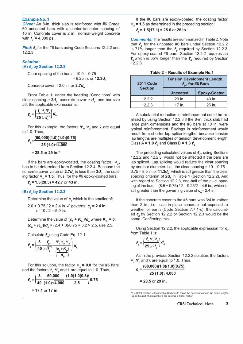
Table 2 – Results of Example No.1
2011 Code
Section
Uncoated Epoxy-Coated
12.2.2 29 in. 43 in.
12.2.3 17 in. 26 in.
A substantial reduction in reinforcement could be re
alized by using Section 12.2.3 if the 8-in. thick slab hadlarge plan dimensions and the #6 bars at 10 in. weretypical reinforcement. Savings in reinforcement would
result from shorter lap splice lengths, because tension
lap lengths are multiples of tension development length
Class A = 1.0 ℓ d
and Class B = 1.3 ℓ d .
The preceding calculated values of ℓ d , using Sections
12.2.2 and 12.2.3, would not be affected if the bars are
lap spliced. Lap splicing would reduce the clear spacingby one bar diameter, i.e., the clear spacing = 10 – 0.75 –
0.75 = 8.5 in. or 11.3d d , which is still greater than the clear
spacing criterion of 2d b in Table 1 (Section 12.2.2). And
with regard to Section 12.2.3, one-half of the c.–c. spac-ing of the bars = (8.5 + 0.75) / 2 = 9.25/2 = 4.6 in., which isstill greater than the governing value of c
b= 2.4 in.
If the concrete cover to the #6 bars was 3/4 in. rathethan 2 in., i.e., cast-in-place concrete not exposed toweather or earth (Code Section 7.7.1-c), the calculat-
ed ℓ d by Section 12.2.2 or Section 12.2.3 would be the
same. Conrming this:
Using Section 12.2.2, the applicable expression for ℓd
from Table 1 is:
f y ψ
t ψ
e ℓ d= ( )
d b 25 λ √f
c ́
⎯
As in the previous Section 12.2.2 solution, the factorsψ
t ,ψ
e and λ are equal to 1.0. Thus,
(60,000)(1.0)(1.0)(0.75)ℓ
d=
25 (1.0)√ ⎯
4,000
= 28.5 or 29 in.
Tension Development Length,
ℓ d, for #6 Bars
*It is CRSI practice in technical publcations to round the development and lap splice lengths
up to the next whole number if the decimal is 0.2 or higher.
8/20/2019 CRSI Tension Development Lengths ACI 318-11
http://slidepdf.com/reader/full/crsi-tension-development-lengths-aci-318-11 4/84 Tension Development and Lap Splice Lengths of Reinforcing Bars under ACI 318-11 [ETN-D-1-13]
Using Section 12.2.3 and Code Eq. 12-1:
c b is smaller of (0.75 + 0.75/2) = 1.1 in. 3 governs
or 10/2 = 5.0 in.
c b = 1.1 in.
(c b+ K
t r )/d
b = (1.1 + 0)/0.75 = 1.5 < 2.5, use 1.5
3 f y ψ
t ψ
e ψ
sℓ
d = ( ) d
b40 λ √f c ́
⎯
(c
b+K
tr
) d
b
Here again, as in the previous Section 12.2.3 solu-
tion, the factor ψs = 0.8 for the #6 bars, and the factors
ψt , ψ
e and λ are equal to 1.0. Thus,
3 60,000 (1.0)1.0(0.8)ℓ
d= ( ) 0.75
40 (1.0)√ ⎯
4,000 1.5
= 28.5 or 29 in.
For 3/4 in. concrete cover, ℓ d = 29 in. using Section
12.2.2 or Section 12.2.3.
The rationale for ℓ d
being the same value, based
on Section 12.2.2 or 12.2.3, is: the value of (c b
+ K t r
)/
d b in Eq.12-1 is equal to 1.5; then dividing the 3/40 in
Eq.12-1 by (c b+ K
t r )/d
b and multiplying by ψ
s results in
((3/40)/1.5)0.8=0.04=1/25, which is the constant in the
expression from Table 1.
Example No. 2
Given: A spread footing has plan dimensions of
13'-6" × 13'-6" and an overall depth of 56 in. The footingis reinforced with 17 – #10 Grade 60 uncoated bars eachway; normal-weight concrete with f
c ´ = 3,000 psi; the col-
umn dimension is 2'-6" square.
Find: Check the required tension development length of
the #10 bars versus the available embedment.
Solution:
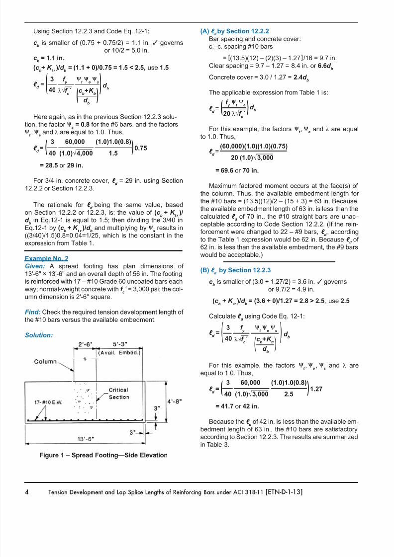
Figure 1 – Spread Footing—Side Elevation
(A) ℓ d by Section 12.2.2
Bar spacing and concrete cover:c.–c. spacing #10 bars
= [(13.5)(12) – (2)(3) – 1.27] /16 = 9.7 in.Clear spacing = 9.7 – 1.27 = 8.4 in. or 6.6d
b
Concrete cover = 3.0 / 1.27 = 2.4d b
The applicable expression from Table 1 is:
f y ψ
t ψ
e
ℓ d= ( )
d b
20 λ √f c ́
⎯
For this example, the factors ψt ,ψ
e and λ are equal
to 1.0. Thus,
(60,000)(1.0)(1.0)(0.75)ℓ
d=
20 (1.0)√ ⎯
3,000
= 69.6 or 70 in.
Maximum factored moment occurs at the face(s) of
the column. Thus, the available embedment length forthe #10 bars = (13.5)(12)/2 – (15 + 3) = 63 in. Becausethe available embedment length of 63 in. is less than thecalculated ℓ
d of 70 in., the #10 straight bars are unac-
ceptable according to Code Section 12.2.2. (If the rein-forcement were changed to 22 – #9 bars, ℓ
d , according
to the Table 1 expression would be 62 in. Because ℓ d of
62 in. is less than the available embedment, the #9 barswould be acceptable.)
(B) ℓ d
by Section 12.2.3
c b is smaller of (3.0 + 1.27/2) = 3.6 in. 3 governs
or 9.7/2 = 4.9 in.
(c b + K
tr )/d
b = (3.6 + 0)/1.27 = 2.8 > 2.5, use 2.5
Calculate ℓ d using Code Eq. 12-1:
3 f y ψ
t ψ
e ψ
sℓ
d = ( ) d
b40 λ √f c ́
⎯
(c b+K
tr )
d b
For this example, the factors ψt ,ψ
e, ψ
s and λ are
equal to 1.0. Thus,
3 60,000 (1.0)1.0(0.8)
ℓ d = ( )
1.27 40 (1.0)√ ⎯
3,000 2.5
= 41.7 or 42 in.
Because the ℓ d of 42 in. is less than the available em-
bedment length of 63 in., the #10 bars are satisfactoryaccording to Section 12.2.3. The results are summarizedin Table 3.
8/20/2019 CRSI Tension Development Lengths ACI 318-11
http://slidepdf.com/reader/full/crsi-tension-development-lengths-aci-318-11 5/8CRSI Technical Note 5
Table 3 – Results of Example No. 2
2011 Code
Section ℓ
d
Available
Embedment
Properly
Anchored?
12.2.2 70 in. 63 in. No
12.2.3 42 in. 63 in. Yes
Example No. 3
Given: This example demonstrates the use of Sections12.2.2 and 12.2.3 for calculating ℓ
d for beam bars with
stirrups. Grade 60, uncoated bottom bars in the interiorspan of a continuous beam. Other data are: b
w = 24 in.;
h = 30 in.; concrete cover to the stirrups is 1.5 in.; normal-
weight concrete with f c ́
= 4,000 psi; #4 U-stirrups arespaced at 13 in. on center and provided throughout ℓ
d .
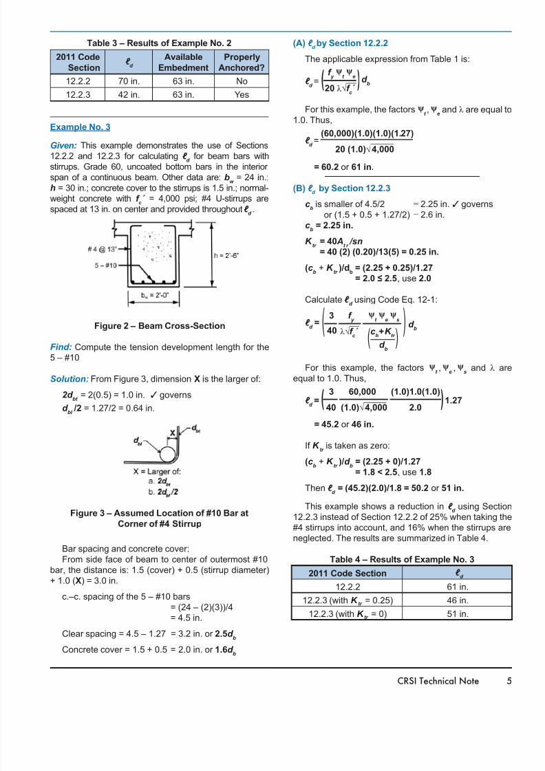
Figure 2 – Beam Cross-Section
Find: Compute the tension development length for the5 – #10
Solution: From Figure 3, dimension X is the larger of:
2d bt
= 2(0.5) = 1.0 in. 3 governs
d bl /2 = 1.27/2 = 0.64 in.
Figure 3 – Assumed Location of #10 Bar at
Corner of #4 Stirrup
Bar spacing and concrete cover:
From side face of beam to center of outermost #10bar, the distance is: 1.5 (cover) + 0.5 (stirrup diameter)
+ 1.0 (X) = 3.0 in.
c.–c. spacing of the 5 – #10 bars = (24 – (2)(3))/4
= 4.5 in.
Clear spacing = 4.5 – 1.27 = 3.2 in. or 2.5d b
Concrete cover = 1.5 + 0.5 = 2.0 in. or 1.6d b
(A) ℓ d by Section 12.2.2
The applicable expression from Table 1 is:
f y ψ
t ψ
e
ℓ d= ( )
d b
20 λ √f c ́
⎯
For this example, the factors ψt ,ψ
e and λ are equal to
1.0. Thus,
(60,000)(1.0)(1.0)(1.27)ℓ d=
20 (1.0)√ ⎯ 4,000
= 60.2 or 61 in.
(B) ℓ d
by Section 12.2.3
c b is smaller of 4.5/2 = 2.25 in. 3 governs
or (1.5 + 0.5 + 1.27/2) = 2.6 in. c
b = 2.25 in.
K tr = 40 A
t r /sn
= 40 (2) (0.20)/13(5) = 0.25 in.
(c b + K tr )/db = (2.25 + 0.25)/1.27= 2.0 ≤ 2.5, use 2.0
Calculate ℓ d using Code Eq. 12-1:
3 f y ψ
t ψ
e ψ
sℓ
d = ( ) d
b40 λ √f c ́
⎯
(c b+K
tr )
d b
For this example, the factors ψt ,ψ
e,ψ
s and λ are
equal to 1.0. Thus,
3 60,000 (1.0)1.0(1.0)ℓ
d=
(
) 1.27
40 (1.0)√ ⎯
4,000 2.0
= 45.2 or 46 in.
If K tr
is taken as zero:
(c b + K
tr )/d
b = (2.25 + 0)/1.27
= 1.8 < 2.5, use 1.8
Then ℓ d
= (45.2)(2.0)/1.8 = 50.2 or 51 in.
This example shows a reduction in ℓ d using Section
12.2.3 instead of Section 12.2.2 of 25% when taking the
#4 stirrups into account, and 16% when the stirrups are
neglected. The results are summarized in Table 4.
Table 4 – Results of Example No. 3
2011 Code Section ℓ d
12.2.2 61 in.
12.2.3 (with K tr = 0.25) 46 in.
12.2.3 (with K tr = 0) 51 in.
8/20/2019 CRSI Tension Development Lengths ACI 318-11
http://slidepdf.com/reader/full/crsi-tension-development-lengths-aci-318-11 6/86 Tension Development and Lap Splice Lengths of Reinforcing Bars under ACI 318-11 [ETN-D-1-13]
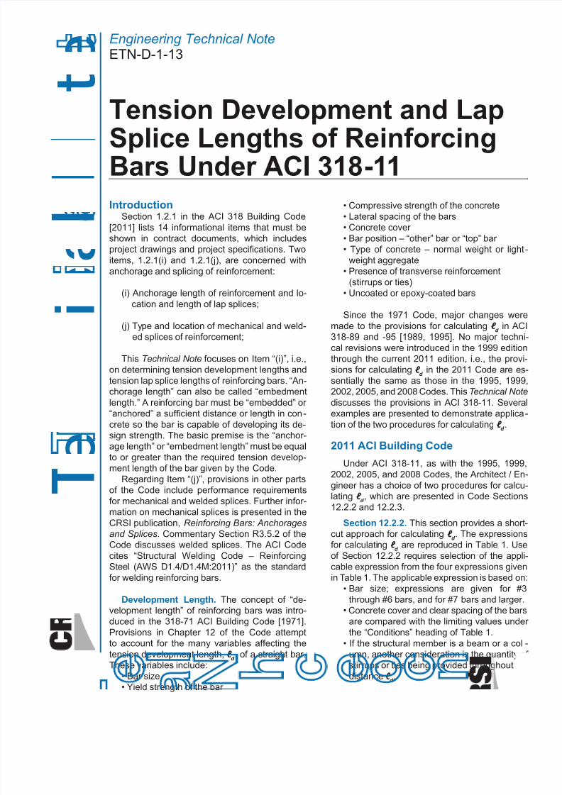
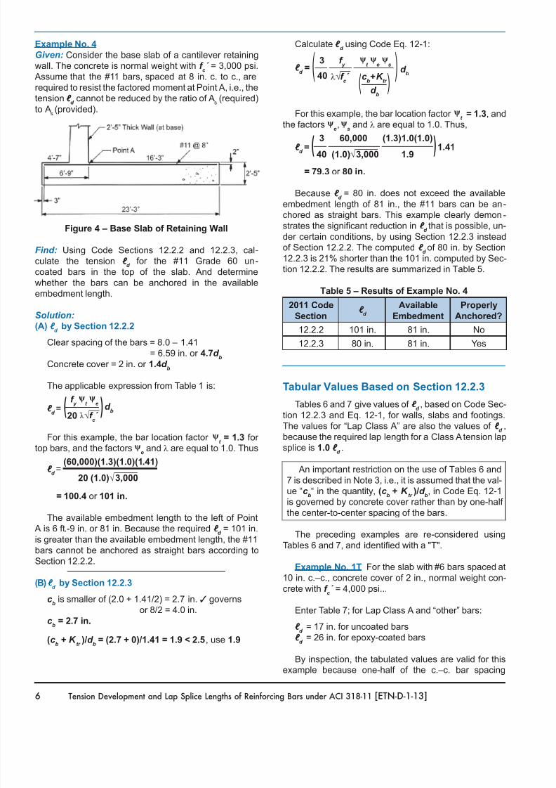
Example No. 4
Given: Consider the base slab of a cantilever retaining
wall. The concrete is normal weight with f c ́
= 3,000 psi.
Assume that the #11 bars, spaced at 8 in. c. to c., arerequired to resist the factored moment at Point A, i.e., the
tension ℓ d
cannot be reduced by the ratio of As (required)
to As(provided).
Figure 4 – Base Slab of Retaining Wall
Find: Using Code Sections 12.2.2 and 12.2.3, cal-culate the tension ℓ
d for the #11 Grade 60 un-
coated bars in the top of the slab. And determinewhether the bars can be anchored in the available
embedment length.
Solution:
(A) ℓ d
by Section 12.2.2
Clear spacing of the bars = 8.0 – 1.41
= 6.59 in. or 4.7d b
Concrete cover = 2 in. or 1.4d b
The applicable expression from Table 1 is:
f y ψ
t ψ
e
ℓ d
= (
)
d b
20 λ √f c ́ ⎯
For this example, the bar location factor ψt = 1.3 for
top bars, and the factors ψe and λ are equal to 1.0. Thus
(60,000)(1.3)(1.0)(1.41)ℓ
d=
20 (1.0)√ ⎯
3,000
= 100.4 or 101 in.
The available embedment length to the left of Point A is 6 ft.-9 in. or 81 in. Because the required ℓ
d = 101 in.
is greater than the available embedment length, the #11
bars cannot be anchored as straight bars according toSection 12.2.2.
(B)ℓ d
by Section 12.2.3
c b is smaller of (2.0 + 1.41/2) = 2.7 in. 3 governs
or 8/2 = 4.0 in.
c b = 2.7 in.
(c b + K
tr )/d
b = (2.7 + 0)/1.41 = 1.9 < 2.5, use 1.9
Calculate ℓ d using Code Eq. 12-1:
3 f y ψ
t ψ
e ψ
sℓ
d = ( ) d
b40 λ √f c ́
⎯
(c b+K
tr )
d b
For this example, the bar location factor ψt = 1.3, and
the factors ψe,ψ
s and λ are equal to 1.0. Thus,
3 60,000 (1.3)1.0(1.0)ℓ
d= ( )
1.41 40 (1.0)√ ⎯
3,000 1.9
= 79.3 or 80 in.
Because ℓ d
= 80 in. does not exceed the availableembedment length of 81 in., the #11 bars can be an-
chored as straight bars. This example clearly demon-
strates the signicant reduction in ℓ dthat is possible, un-
der certain conditions, by using Section 12.2.3 instead
of Section 12.2.2. The computed ℓ d of 80 in. by Section
12.2.3 is 21% shorter than the 101 in. computed by Sec-tion 12.2.2. The results are summarized in Table 5.
Table 5 – Results of Example No. 4
2011 Code
Sectionℓ
d
Available
Embedment
Properly
Anchored?
12.2.2 101 in. 81 in. No
12.2.3 80 in. 81 in. Yes
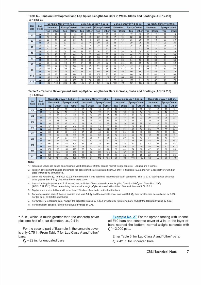
Tabular Values Based on Section 12.2.3
Tables 6 and 7 give values of ℓ d, based on Code Sec-
tion 12.2.3 and Eq. 12-1, for walls, slabs and footings.The values for “Lap Class A” are also the values of ℓ
d,
because the required lap length for a Class A tension lap
splice is 1.0 ℓ d.
An important restriction on the use of Tables 6 and7 is described in Note 3, i.e., it is assumed that the val-
ue “c b“ in the quantity, (c
b + K
tr )/d
b, in Code Eq. 12-1
is governed by concrete cover rather than by one-half
the center-to-center spacing of the bars.
The preceding examples are re-considered usingTables 6 and 7, and identied with a "T".
Example No. 1T For the slab with #6 bars spaced at10 in. c.–c., concrete cover of 2 in., normal weight con-
crete with f c ́
= 4,000 psi...
Enter Table 7; for Lap Class A and “other” bars:
ℓ d
= 17 in. for uncoated bars
ℓ d
= 26 in. for epoxy-coated bars
By inspection, the tabulated values are valid for thisexample because one-half of the c.–c. bar spacing
8/20/2019 CRSI Tension Development Lengths ACI 318-11
http://slidepdf.com/reader/full/crsi-tension-development-lengths-aci-318-11 7/8CRSI Technical Note 7
Table 6 – Tension Development and Lap Splice Lengths for Bars in Walls, Slabs and Footings (ACI 12.2.3)
Notes:
1. Tabulated values are based on a minimum yield strength of 60,000 psi and normal-weight concrete. Lengths are in inches.
2. Tension development lengths and tension lap splice lengths are calculated per ACI 318-11, Sections 12.2.3 and 12.15, respectively, with bar
sizes limited to #3 through #11.
3. When the variable “c b” from ACI 12.2.3 was calculated, it was assumed that concrete cover controlled. That is, c.–c. spacing was assumed
to be greater than 1.0 d b plus twice the concrete cover.
4. Lap splice lengths (minimum of 12 inches) are multiples of tension development lengths; Class A =1.0 ℓ d and Class B = 1.3 ℓ d (ACI 318 12.15.1). When determining the lap splice length,ℓ d is calculated without the 12-inch minimum of ACI 12.2.1.
5. Top bars are horizontal bars with more than 12 inches of concrete cast below the bars.
6. For epoxy-coated bars, if the c.-c. spacing is at least7.0 d b and the concrete cover is at least3.0 d b, then lengths may be multiplied by 0.918
(for top bars) or 0.8 (for other bars).
7. For Grade 75 reinforcing bars, multiply the tabulated values by 1.25. For Grade 80 reinforcing bars, multiply the tabulated values by 1.33.
8. For lightweight concrete, divide the tabulated values by 0.75.
Bar
Size
Lap
Class
Concrete Cover = 0.75 in. Concrete Cover = 1.50 in. Concrete Cover = 2.00 in. Concrete Cover = 3.00 in.
Uncoated Epoxy-Coated Uncoated Epoxy-Coated Uncoated Epoxy-Coated Uncoated Epoxy-Coated
Top Other Top Other Top Other Top Other Top Other Top Other Top Other Top Other
#3A 13 12 17 15 13 12 17 15 13 12 17 15 13 12 17 15
B 17 13 22 20 17 13 22 20 17 13 22 20 17 13 22 20
#4A 22 17 28 25 17 13 23 20 17 13 23 20 17 13 23 20
B 28 22 37 32 23 17 29 26 23 17 29 26 23 17 29 26
#5A 32 24 41 37 22 17 28 25 22 17 28 25 22 17 28 25
B 41 32 54 47 28 22 37 32 28 22 37 32 28 22 37 32
#6A 43 33 56 50 26 20 34 30 26 20 34 30 26 20 34 30
B 56 43 73 64 34 26 44 39 34 26 44 39 34 26 44 39
#7A 69 53 90 80 43 33 55 49 38 29 49 43 38 29 49 43
B 90 69 117 104 55 43 72 64 49 38 64 56 49 38 64 56
#8A 86 66 112 99 54 41 70 62 43 33 56 50 43 33 56 50
B 111 86 146 128 70 54 91 80 56 43 73 64 56 43 73 64
#9A 104 80 136 120 66 51 86 76 53 41 70 61 48 37 63 56
B 135 104 176 155 86 66 112 99 69 53 90 80 63 48 82 73
#10A 125 96 163 144 81 62 106 93 66 51 86 76 55 42 71 63
B 162 125 212 187 105 81 137 121 85 66 111 98 71 55 93 82
#11A 146 113 191 169 97 74 126 111 79 61 103 91 61 47 79 70
B 190 146 248 219 125 97 164 145 102 79 134 118 79 61 103 91
f’ c = 3,000 psi
Table 7 – Tension Development and Lap Splice Lengths for Bars in Walls, Slabs and Footings (ACI 12.2.3)
Bar
Size
Lap
Class
Concrete Cover = 0.75 in. Concrete Cover = 1.50 in. Concrete Cover = 2.00 in. Concrete Cover = 3.00 in.Uncoated Epoxy-Coated Uncoated Epoxy-Coated Uncoated Epoxy-Coated Uncoated Epoxy-Coated
Top Other Top Other Top Other Top Other Top Other Top Other Top Other Top Other
#3A 12 12 15 13 12 12 15 13 12 12 15 13 12 12 15 13
B 15 12 19 17 15 12 19 17 15 12 19 17 15 12 19 17
#4A 19 15 24 22 15 12 20 17 15 12 20 17 15 12 20 17
B 24 19 32 28 20 15 25 22 20 15 25 22 20 15 25 22
#5A 28 21 36 32 19 15 24 22 19 15 24 22 19 15 24 22
B 36 28 47 41 24 19 32 28 24 19 32 28 24 19 32 28
#6A 37 29 49 43 22 17 29 26 22 17 29 26 22 17 29 26
B 48 37 63 56 29 22 38 34 29 22 38 34 29 22 38 34
#7A 60 46 78 69 37 28 48 42 33 25 43 38 33 25 43 38
B 78 60 102 90 48 37 62 55 42 33 55 49 42 33 55 49
#8A 74 57 97 86 47 36 61 54 37 29 49 43 37 29 49 43
B 96 74 126 111 60 47 79 70 48 37 63 56 48 37 63 56
#9A 90 69 117 104 57 44 75 66 46 36 60 53 42 32 55 48
B 117 90 153 135 74 57 97 86 60 46 78 69 55 42 71 63
#10 A 108 83 141 125 70 54 92 81 57 44 74 66 47 36 62 55B 140 108 183 162 91 70 119 105 74 57 97 85 61 47 80 71
#11A 127 98 166 146 84 64 109 97 68 53 89 79 52 40 69 60
B 165 127 215 190 109 84 142 125 89 68 116 102 68 52 89 79
f’ c = 4,000 psi
= 5 in., which is much greater than the concrete cover
plus one-half of a bar diameter, i.e., 2.4 in.
For the second part of Example 1, the concrete coveris only 0.75 in. From Table 7 for Lap Class A and “other”bars:
ℓ d
= 29 in. for uncoated bars
Example No. 2T For the spread footing with uncoat-
ed #10 bars and concrete cover of 3 in. to the layer ofbars nearest the bottom, normal-weight concrete with
f c ́
= 3,000 psi...
Enter Table 6; for Lap Class A and “other” bars:
ℓ d
= 42 in. for uncoated bars
8/20/2019 CRSI Tension Development Lengths ACI 318-11
http://slidepdf.com/reader/full/crsi-tension-development-lengths-aci-318-11 8/8
933 North Plum Grove Rd.Schaumburg, IL 60173-4758
p. 847-517-1200 • f. 847-517-1206www.crsi.org
Regional Ofces Nationwide A Service of the Concrete Reinforcing Steel Institute
©2013 This publication, or any part thereof, may not be
reproduced without the expressed written consent of CRSI.
Printed in the U.S.A.
Contributors: Dr. David P. Gustafson, P.E., S.E. and Anthony L. Felder, P.E., with subsequentcontributions from Neal S. Anderson, P.E., S.E..
Keywords: development, lap splices
Reference: Concrete Reinforcing Steel Institute-CRSI [2013], “Tension Development and LapSplice Lengths of Reinforcing Bars Under ACI 318-11,” CRSI Technical Note ETN-D-1-13, Con-crete Reinforcing Steel Institute, Schaumburg, Illinois, 8 pp.
Note: This publication is intended for the use of professionals competent to evaluate the signi-cance and limitations of its contents and who will accept responsibility for the application of thematerial it contains. The Concrete Reinforcing Steel Institute reports the foregoing material asa matter of information and , therefore, disclaims any and all responsibility for application of thestated principles or for the accuracy of the sources other than material developed by the Institute.
Example No. 3T Tables 6 and 7 are not intended forand consequently are not applicable for closely-spacedbars in beams. For the beam in Example 3, the value ofc
bwould be governed by one-half of the c.–c. spacing of
the bars, i.e., 2.25 in., rather than by the concrete cover
plus one-half of a bar diameter, i.e., 2.6 in.
Example No. 4T For the base slab of the cantilever
retaining wall with uncoated #11 bars spaced at 8 in. c.–c., concrete cover of 2 in., normal-weight concrete with
f c ́
= 3,000 psi...
Enter Table 6; for Lap Class A and “top” bars:
ℓ d
= 79 in. for uncoated bars
Summary
This Technical Note discusses the provisions in Sec-
tions 12.2.2 and 12.2.3 of the 2011 ACI Building Code for
determining the tension development lengths, ℓ d , of re-
inforcing bars. Several examples are presented to com-
plement the discussion. The examples serve to identifysome of the conditions and the structural members for
which the more rigorous provisions in Section 12.2.3 can
be used advantageously.
References
American Concrete Institute – ACI Committee 318
[1971], Building Code Requirements for Reinforced
Concrete (ACI 318-71), American Concrete Institute,
Detroit, Michigan, 78 pp.
American Concrete Institute – ACI Committee 318
[1977], Building Code Requirements for ReinforcedConcrete (ACI 318-77), American Concrete Institute,
Detroit, Michigan, 103 pp.
American Concrete Institute – ACI Committee 318
[1983], Building Code Requirements for Reinforced
Concrete (ACI 318-83), American Concrete Institute,
Detroit, Michigan, 111 pp.
American Concrete Institute – ACI Committee 318
[1989], Building Code Requirements for Reinforced
Concrete (ACI 318-89) and Commentary (ACI 318R-89),
American Concrete Institute, Detroit, Michigan, 353 pp.
American Concrete Institute – ACI Committee 318
[1995], Building Code Requirements for Structural Con-
crete (ACI 318-95) and Commentary (ACI 318R-95),
American Concrete Institute, Detroit, Michigan, 369 pp.
American Concrete Institute – ACI Committee 318
[1999], Building Code Requirements for Structural Con-
crete (ACI 318-99) and Commentary (ACI 318R-99),
American Concrete Institute, Farmington Hills, Michigan,
391 pp.
American Concrete Institute – ACI Committee 318
[2002], Building Code Requirements for Structural Con-
crete (ACI 318-02) and Commentary (ACI 318R-02),
American Concrete Institute, Farmington Hills, Michigan,
443 pp.
American Concrete Institute – ACI Committee 318[2005], Building Code Requirements for Structural Con-
crete (ACI 318-05) and Commentary (ACI 318R-05),
American Concrete Institute, Farmington Hills, Michigan,
430 pp.
American Concrete Institute – ACI Committee 318
[2008], Building Code Requirements for Structural Con-
crete (ACI 318-08) and Commentary (ACI 318R-08),
American Concrete Institute, Farmington Hills, Michigan,465 pp.
American Concrete Institute – ACI Committee 318
[2011], Building Code Requirements for Structural Con-
crete (ACI 318-11) and Commentary (ACI 318R-11), American Concrete Institute, Farmington Hills, Michigan,
473 pp.
American Welding Society [2011], Structural Welding
Code – Reinforcing Steel (AWS D1.4:2011), American
Welding Society, Miami, Florida, 72 pp.
Concrete Reinforcing Steel Institute [2008], Reinforc-
ing Bars: Anchorages and Splices, 5th Edition, Concrete
Reinforcing Steel Institute, Schaumburg, Illinois, 64 pp.