Embed Size (px)
Citation preview
WaveSurfer® MXs-B and MSO MXs-B Oscilloscopes 200 MHz – 1 GHz
WaveSurfer® MXs-B• 200 MHz, 400 MHz, 600 MHz
and 1 GHz Bandwidths
• Up to 10 GS/s Sample Rate
• 16 Mpts/Ch Memory, 32 Mpts Interleaved
• Fast Processing of Long Memory and Math
• Responsive User Interface
• WaveStream™ Fast Viewing Mode
• WaveScan™ – Advanced Search and Find
• LabNotebook Documentation and Report Generation
• 10.4” Touch Screen Display
• LXI Compliant
MSO MXs-BAll the great features of the WaveSurfer MXs-B plus:
• 18 Digital Channels
• Max. Digital Signal Speed of 250 MHz
• Analog and Digital Cross Pattern Triggering
The WaveSurfer® MXs-B and MSO MXs-B oscilloscopes pack high performance hardware, powerful waveform processing and advanced math, measurement and debug tools into a compact form factor with a large touch screen display and intuitive user interface.
With up to 10 GS/s sample rate and
32 Mpts of memory WaveSurfer can
capture large amounts of data at
very high sample rates. Other
oscilloscopes offer long memory but
they bog down trying to process or
display it. WaveSurfer handles large
amounts of data quickly providing
fast processing of long memory even
when using math and measurement
functions. The software responds
immediately to the user inputs even
while processing data.
System debug often requires more
than analog channels. The MSO
MXs-B delivers 18 digital channels
which can capture digital signals of
up to 250 MHz. The MSO MXs-B
offer analog and digital cross-trig-
gering plus measurement tools to
help debug digital busses. Teledyne
LeCroy’s WaveScan™ search and find
tool will scan both analog and digital
channels for anamolies plus scan
multiple digital lines for a parallel
bus pattern.
Key Features
2
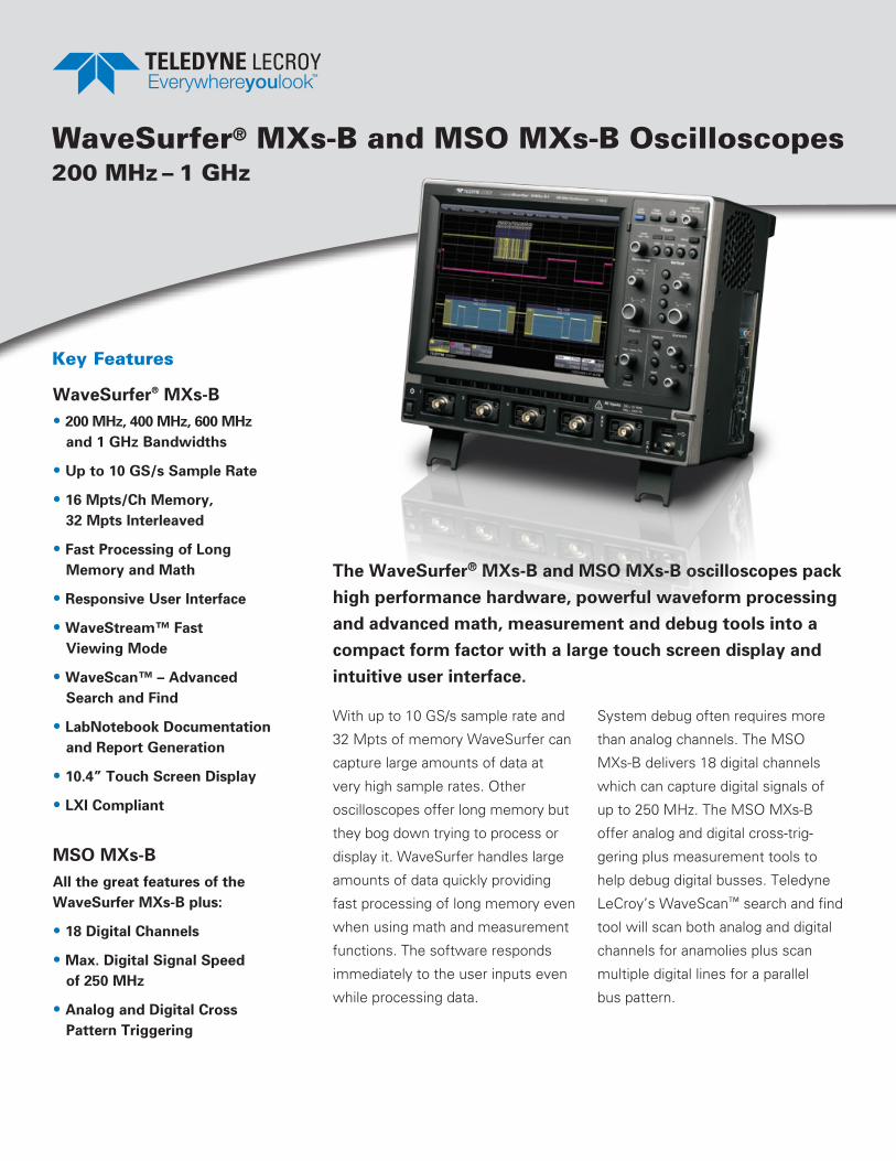
TOUCH SCReeN SIMPLICITy
New Surfer image
Don’t waste time searching through a complex menu
structure to find the proper setting. Configuring the Wave-
Surfer is simple thanks to the intuitive touch screen user
interface. Everything on the screen is interactive. To adjust
channel, timebase, or trigger settings, simply touch the
associated descriptor box and the appropriate menu is
opened. Measurements can be touched to adjust their
settings and cursors can be positioned precisely by touch-
ing and dragging them to the proper location. A box can be
drawn around a portion of a waveform to create a zoom of
that waveform. Even waveform offset and delay can be
adjusted simply by touching and dragging the waveform.

3
embedded Controller Design and Debug
Save time when working with embed-
ded controllers by adding high-perfor-
mance mixed signal capability with the
MSO MXs-B. Capture digital signals up
to 250 MHz with up to 10 Mpts/Ch
memory, 1 GS/s and 18 channels.
Quickly and easily isolate specific
serial data events with optional I2C,
SPI, UART, RS-232, USB 1.0/1.1/2.0,
USB2-HSIC, 10/100Base T ENET, Audio
(I2S, LJ, RJ, TDM), MIL-STD-1553,
ARINC 429, MIPI D-PHY, DigRF, CAN,
LIN, FlexRay™, SENT, Manchester, and
NRZ trigger and decode options.
TOUCH SCReeN SIMPLICITy
Advanced Math and Measure Use automatic measurement param-
eters with statistics and histicons
as well as math functions to under-
stand every waveform detail.
WaveStream Fast Viewing Mode
WaveStream provides a vibrant,
intensity graded (256 levels) display
with a fast update to closely
simulate the look and feel of an
analog oscilloscope.
ADVANCeD TOOLS FOR WAVeFORM ANALySIS
Simple Power Measurements Measure and analyze operating
characteristics of power conversion
devices and circuits.
LabNotebook Documentation and Report Generation Tool Save all results and data with a
single button press and create
custom reports with LabNotebook.
WaveScan Advanced Search and Find Tool
Quickly search waveforms for
runts, glitches or other anomalies
with WaveScan.
Sequence Mode Acquisition
Capture many fast pulses in
quick succession or events sepa-
rated by long periods of time.

4
The WaveSurfer MXs-B and MSO MXs-B oscilloscopes makes everyday testing simpler and easier. The intuitive user interface and streamlined front panel make it easy to turn on the oscilloscope and start making measure-ments. The interface is designed so that all the common measurements and functions are just one touch away.
1. Only 15 cm (6”) DeepThe most space-efficient oscilloscope for your
bench from 200 MHz to 1 GHz.
2. Local Language User InterfaceSelect from 10 language preferences. Add a front
panel overlay with your local language.
3. Bright 10.4” DisplayYou’ll never use a small display oscilloscope again.
A fantastic viewing angle makes it easy to view.
INTUITIVe USeR INTeRFACe TO FIND PROBLeMS FASTeR
4
3
2
1
5
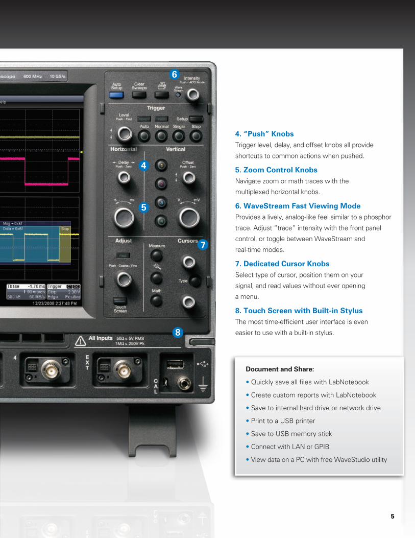
4. “Push” Knobs Trigger level, delay, and offset knobs all provide
shortcuts to common actions when pushed.
5. Zoom Control Knobs Navigate zoom or math traces with the
multiplexed horizontal knobs.
6. WaveStream Fast Viewing Mode Provides a lively, analog-like feel similar to a phosphor
trace. Adjust “trace” intensity with the front panel
control, or toggle between WaveStream and
real-time modes.
7. Dedicated Cursor Knobs Select type of cursor, position them on your
signal, and read values without ever opening
a menu.
8. Touch Screen with Built-in StylusThe most time-efficient user interface is even
easier to use with a built-in stylus.
INTUITIVe USeR INTeRFACe TO FIND PROBLeMS FASTeR
Document and Share:
• Quickly save all files with LabNotebook
• Create custom reports with LabNotebook
• Save to internal hard drive or network drive
• Print to a USB printer
• Save to USB memory stick
• Connect with LAN or GPIB
• View data on a PC with free WaveStudio utility
5
4
5
7
8
6
6
IDeNTIFy AND ISOLATe PROBLeMS FASTeR
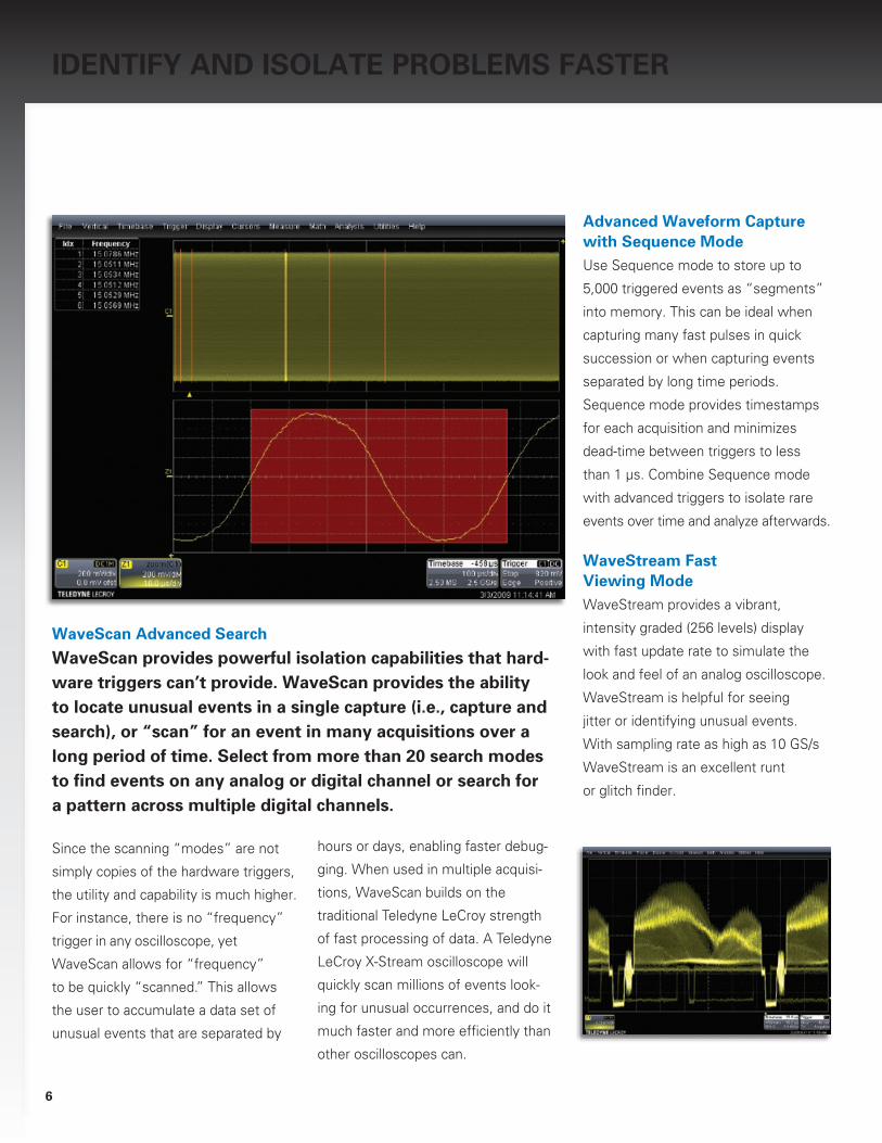
WaveScan Advanced Search
WaveScan provides powerful isolation capabilities that hard-ware triggers can’t provide. WaveScan provides the ability to locate unusual events in a single capture (i.e., capture and search), or “scan” for an event in many acquisitions over a long period of time. Select from more than 20 search modes to find events on any analog or digital channel or search for a pattern across multiple digital channels.
Since the scanning “modes” are not
simply copies of the hardware trig gers,
the utility and capa bility is much higher.
For instance, there is no “frequency”
trigger in any oscilloscope, yet
WaveScan allows for “frequency”
to be quickly “scanned.” This allows
the user to accumulate a data set of
unusual events that are separated by
hours or days, enabling faster debug-
ging. When used in multiple acquisi-
tions, WaveScan builds on the
traditional Teledyne LeCroy strength
of fast processing of data. A Teledyne
LeCroy X-Stream oscilloscope will
quickly scan millions of events look-
ing for unusual occurrences, and do it
much faster and more efficiently than
other oscilloscopes can.
Advanced Waveform Capture with Sequence ModeUse Sequence mode to store up to
5,000 triggered events as “segments”
into memory. This can be ideal when
capturing many fast pulses in quick
succession or when capturing events
separated by long time periods.
Sequence mode provides timestamps
for each acquisition and minimizes
dead-time between triggers to less
than 1 μ s. Combine Sequence mode
with advanced triggers to isolate rare
events over time and analyze afterwards.
WaveStream Fast Viewing ModeWaveStream provides a vibrant,
intensity graded (256 levels) display
with fast update rate to simulate the
look and feel of an analog oscilloscope.
WaveStream is helpful for seeing
jitter or identifying unusual events.
With sampling rate as high as 10 GS/s
WaveStream is an excellent runt
or glitch finder.
7
IDeNTIFy AND ISOLATe PROBLeMS FASTeR LABNOTeBOOK™ A UniqUe Tool for DocUmenTATion AnD reporT GenerATion
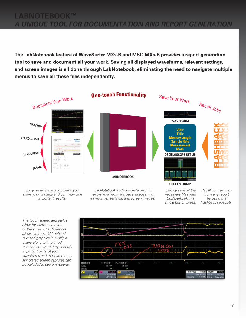
The LabNotebook feature of WaveSurfer MXs-B and MSO MXs-B provides a report generation tool to save and document all your work. Saving all displayed waveforms, relevant settings, and screen images is all done through LabNotebook, eliminating the need to navigate multiple menus to save all these files independently.
The touch screen and stylus allow for easy annotation of the screen. LabNotebook allows you to add freehand text and graphics in multiple colors along with printed text and arrows to help identify important parts of your waveforms and measurements. Annotated screen captures can be included in custom reports.
V/divT/div
Memory LengthSample Rate
MeasurementMath
WAVeFORM
OSCILLOSCOPe SeT UP
SCReeN DUMP
PRINTeR
HARD DRIVe
USB DRIVe
Document Your Work One-touch Functionality Save Your Work Recall Jobs
Easy report generation helps you share your findings and communicate
important results.
LabNotebook adds a simple way to report your work and save all essential
waveforms, settings, and screen images.
Quickly save all the necessary files with LabNotebook in a
single button press.
Recall your settings from any report
by using the Flashback capability.
FLA
SH
BA
CK
FLA
SH
BA
CK
FLA
SH
BA
CK
LABNOTeBOOK

8
High-performance Mixed Signal CapabilitiesEmbedded controller design and debug
involves capturing and viewing a
number of different types of signals.
These signals are typically a mix of
analog, digital, and serial data wave-
forms from a combination of analog
sensors, microcontrollers and peripheral
devices. With the ability to capture digital
signals with speeds up to 250 MHz
and long memory of 10 Mpts/Ch the
MSO MXs-B provides unmatched
mixed signal performance. The
MSO MXs-B is the ideal tool for testing
embedded systems with 8-bit micro-
controllers or slower digital signals.
With 18 digital inputs each with
250 MHz max. input frequency and
10 Mpts/Ch memory, the MSO MXs-B
is an outstanding value and provides
a complete set of tools for embedded
system testing.
extensive TriggeringThe MSO MXs-B has extensive digital
trigger capabilities. Normal oscilloscope
triggers will operate on digital inputs.
Cross-pattern triggering allows for sim-
ple or complex trigger patterns to be
setup with any combination of analog
and digital channels. Event triggering
can be configured to arm on an analog
signal and trigger on a digital pattern.
Quick Mixed Signal Setup, easy-to-useUnlike a traditional Logic Analyzer, the
MSO MXs-B is easy to use. A simple
connection links the oscilloscope with
the digital inputs so users can start
viewing signals and begin debugging
quickly. In addition, all standard
oscilloscope tools are readily
accessible. Signal debug is simple,
using standard oscilloscope tools,
such as cursors, measurement
parameters, and zooming.
eMBeDDeD CONTROLLeR DeSIGN AND DeBUG
Teledyne LeCroy’s versatile MSO MXs-B mixed signal oscilloscope combines the powerful WaveSurfer MXs-B with the flexibility of digital inputs using the MS-250. In addition, the many triggering and decoding options turn the MSO MXs-B into an all-in-one analog, digital, and serial data trigger, acquisition, and debug machine.

9
View decoded protocol information on top of physical layer waveforms and trigger on protocol specific messages.
Powerful Serial Data Triggers The serial data trigger will quickly
isolate events on a bus eliminating
the need to set manual triggers and
hoping to catch the right information.
Trigger conditions can be entered in
binary or hexadecimal formats and
conditional trigger capabilities even
allow triggering on a range of differ-
ent events.
Intuitive, Color-Coded Decode OverlayProtocol decoding is shown directly
on the waveform with an intuitive,
color-coded overlay and presented in
binary, hex or ASCII. Decoding on the
MSO MXs-B is fast even with long
memory and zooming in to the
waveform shows precise byte by
byte decoding.
Table Summary and Search/ZoomTo further simplify the debug process
all decoded data can be displayed in a
table below the waveform grid.
Selecting an entry in the table with
the touch screen will display just that
event. Additionally, built-in search
functionality will find specific de-
coded values.
SeRIAL TRIGGeR AND DeCODe OPTIONS
Supported Serial Data Protocols
• I2C, SPI, UART
• CAN, LIN, FlexRay™, SENT
• Ethernet 10/100BaseT, USB 1.0/1.1/2.0, USB 2.0-HSIC
• Audio (I2S, LJ, RJ, TDM)
• MIL-STD-1553, ARINC 429
• MIPI D-PHY, DigRF 3G, DigRF v4
• Manchester, NRZ
Debugging serial data busses can be confusing and time consuming. The serial data and decode options for MSO MXs-B provide time saving tools for serial bus debug and validation.
10
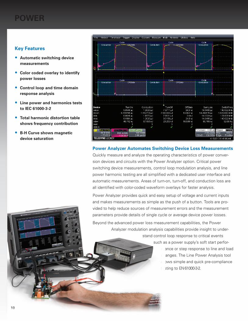
Power Analyzer Automates Switching Device Loss MeasurementsQuickly measure and analyze the operating characteristics of power conver-
sion devices and circuits with the Power Analyzer option. Critical power
switching device measurements, control loop modulation analysis, and line
power harmonic testing are all simplified with a dedicated user interface and
automatic measurements. Areas of turn-on, turn-off, and conduction loss are
all identified with color-coded waveform overlays for faster analysis.
Power Analyzer provides quick and easy setup of voltage and current inputs
and makes measurements as simple as the push of a button. Tools are pro-
vided to help reduce sources of measurement errors and the measurement
parameters provide details of single cycle or average device power losses.
Beyond the advanced power loss measurement capabilities, the Power
Analyzer modulation analysis capabilities provide insight to under-
stand control loop response to critical events
such as a power supply’s soft start perfor-
mance or step response to line and load
changes. The Line Power Analysis tool
allows simple and quick pre-compliance
testing to EN 61000-3-2.
POWeR
Key Features
• Automatic switching device measurements
• Color coded overlay to identify power losses
• Control loop and time domain response analysis
• Line power and harmonics tests to IeC 61000-3-2
• Total harmonic distortion table shows frequency contribution
• B-H Curve shows magnetic device saturation
11
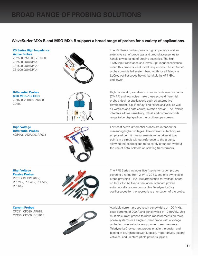
BROAD RANGe OF PROBING SOLUTIONS
WaveSurfer MXs-B and MSO MXs-B support a broad range of probes for a variety of applications.
ZS Series High Impedance Active Probes ZS2500, ZS1500, ZS1000, ZS2500-QUADPAK, ZS1500-QUADPAK, ZS1000-QUADPAK
The ZS Series probes provide high impedance and an extensive set of probe tips and ground accessories to handle a wide range of probing scenarios. The high 1 MΩ input resistance and low 0.9 pF input capacitance mean this probe is ideal for all frequencies. The ZS Series probes provide full system bandwidth for all Teledyne LeCroy oscilloscopes having bandwidths of 1 GHz and lower.
Differential Probes (200 MHz – 1.5 GHz)ZD1500, ZD1000, ZD500, ZD200
High bandwidth, excellent common-mode rejection ratio (CMRR) and low noise make these active differential probes ideal for applications such as automotive development (e.g. FlexRay) and failure analysis, as well as wireless and data communication design. The ProBus interface allows sensitivity, offset and common-mode range to be displayed on the oscilloscope screen.
High Voltage Differential ProbesADP305, ADP300, AP031
Low cost active differential probes are intended for measuring higher voltages. The differential techniques employed permit measurements to be taken at two points in a circuit without reference to the ground, allowing the oscilloscope to be safely grounded without the use of opto-isolators or isolating transformers.
High Voltage Passive ProbesPPE1.2KV, PPE20KV, PPE2KV, PPE4KV, PPE5KV, PPE6KV
The PPE Series includes five fixed-attenuation probes covering a range from 2 kV to 20 kV, and one switchable probe providing ÷10/÷100 attenuation for voltage inputs up to 1.2 kV. All fixed-attenuation, standard probes automatically rescale compatible Teledyne LeCroy oscilloscopes for the appropriate attenuation of the probe.
Current ProbesCP031, CP030, AP015, CP150, CP500, DCS015
Available current probes reach bandwidths of 100 MHz, peak currents of 700 A and sensitivities of 10 mA/div. Use multiple current probes to make measurements on three-phase systems or a single current probe with a voltage probe to make instantaneous power measurements. Teledyne LeCroy current probes enable the design and testing of switching power supplies, motor drives, electric vehicles, and uninterruptible power supplies.

12
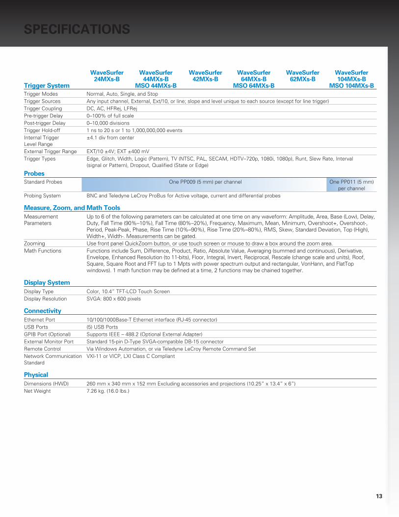
SPeCIFICATIONS
WaveSurfer WaveSurfer WaveSurfer WaveSurfer WaveSurfer WaveSurfer Analog Channels 24MXs-B 44MXs-B 42MXs-B 64MXs-B 62MXs-B 104MXs-B – Vertical MSO 44MXs-B MSO 64MXs-B MSO 104MXs-BBandwidth (@ 50 Ω) 200 MHz 400 MHz 400 MHz 600 MHz 600 MHz 1 GHzRise Time 1.75 ns 875 ps 875 ps 525 ps 525 ps 350 psInput Channels 4 4 2 4 2 4Vertical Resolution 8 bitsVertical Sensitivity (V/div) 2 mV/div–10 V/div (1 MΩ); 2 mV/div–1 V/div (50 Ω)Vertical (DC Gain) ±1.0% of full scale (typical); ±1.5% of full scale ≥ 10 mV/div (warranted) AccuracyBW Limit 20 MHz 20 MHz, 200 MHzMaximum Input Voltage 50 Ω: 5 Vrms, 1 MΩ: 400 V max. (DC + Peak AC ≤ 5 kHz) 50 Ω: 5 Vrms 1 MΩ: 250 V max. (DC + Peak AC ≤10 kHz)Input Coupling AC, DC, GND (DC and GND for 50 Ω)Input Impedance 1 MΩ || 16 pF, or 50 Ω
Analog Channels – AcquisitionSample Rate 2.5 GS/s 5 GS/s 5 GS/s (Single-shot) (10 GS/s Interleaved)Sample Rate 50 GS/s (Repetitive)Record Length 16 Mpts/Ch (all channels), 32 Mpts (interleaved)Capture Time Up to 3.2 ms at full sample rate on all four channelsAcquisition Modes Real Time, Roll, RIS (Random Interleaved Sampling), WaveStream (Fast Viewing Mode), Sequence (Segmented Memory
up to 5,000 segments with 1μ s intersegment time)Time Base Range 200 ps/div–1000 s/div (roll mode from 500 ms/div–1000 s/div)Time Base Accuracy ≤ 5 ppm @ 25 °C (typical) (≤ 10 ppm @ 5–40 °C)
Digital Channels – VerticalInput Channels 18 (D0–D17) 18 (D0–D17) 18 (D0–D17)Input Impedance 100 kΩ || 5.0 pF 100 kΩ || 5.0 pF 100 kΩ || 5.0 pFMaximum Input Voltage ±30 V non-destruct ±30 V non-destruct ±30 V non-destructThreshold Groupings D0–D8, D9–D17 D0–D8, D9–D17 D0–D8, D9–D17Threshold Selections TTL, ECL, CMOS, TTL, ECL, CMOS, TTL, ECL, CMOS, PECL, LVDS, PECL, LVDS, PECL, LVDS, User Defined User Defined User Defined
Digital Channels – AcquisitionSample Rate 1 GS/s 1 GS/s 1 GS/sRecord Length 10 Mpts/Ch 10 Mpts/Ch 10 Mpts/ChMinimum Detectable 2 ns 2 ns 2 ns Pulse WidthMaximum Input 250 MHz 250 MHz 250 MHz Frequency
13
SPeCIFICATIONS
WaveSurfer WaveSurfer WaveSurfer WaveSurfer WaveSurfer WaveSurfer 24MXs-B 44MXs-B 42MXs-B 64MXs-B 62MXs-B 104MXs-B Trigger System MSO 44MXs-B MSO 64MXs-B MSO 104MXs-BTrigger Modes Normal, Auto, Single, and StopTrigger Sources Any input channel, External, Ext/10, or line; slope and level unique to each source (except for line trigger)Trigger Coupling DC, AC, HFRej, LFRejPre-trigger Delay 0–100% of full scalePost-trigger Delay 0–10,000 divisionsTrigger Hold-off 1 ns to 20 s or 1 to 1,000,000,000 eventsInternal Trigger ±4.1 div from center Level RangeExternal Trigger Range EXT/10 ±4V; EXT ±400 mVTrigger Types Edge, Glitch, Width, Logic (Pattern), TV (NTSC, PAL, SECAM, HDTV–720p, 1080i, 1080p), Runt, Slew Rate, Interval
(signal or Pattern), Dropout, Qualified (State or Edge)
Probes Standard Probes One PP009 (5 mm) per channel One PP011 (5 mm) per channelProbing System BNC and Teledyne LeCroy ProBus for Active voltage, current and differential probes
Measure, Zoom, and Math ToolsMeasurement Up to 6 of the following parameters can be calculated at one time on any waveform: Amplitude, Area, Base (Low), Delay, Parameters Duty, Fall Time (90%–10%), Fall Time (80%–20%), Frequency, Maximum, Mean, Minimum, Overshoot+, Overshoot-,
Period, Peak-Peak, Phase, Rise Time (10%–90%), Rise Time (20%–80%), RMS, Skew, Standard Deviation, Top (High), Width+, Width-. Measurements can be gated.
Zooming Use front panel QuickZoom button, or use touch screen or mouse to draw a box around the zoom area.Math Functions Functions include Sum, Difference, Product, Ratio, Absolute Value, Averaging (summed and continuous), Derivative,
Envelope, Enhanced Resolution (to 11-bits), Floor, Integral, Invert, Reciprocal, Rescale (change scale and units), Roof, Square, Square Root and FFT (up to 1 Mpts with power spectrum output and rectangular, VonHann, and FlatTop windows). 1 math function may be defined at a time, 2 functions may be chained together.
Display SystemDisplay Type Color, 10.4” TFT-LCD Touch ScreenDisplay Resolution SVGA: 800 x 600 pixels
ConnectivityEthernet Port 10/100/1000Base-T Ethernet interface (RJ-45 connector)USB Ports (5) USB PortsGPIB Port (Optional) Supports IEEE – 488.2 (Optional External Adapter)External Monitor Port Standard 15-pin D-Type SVGA-compatible DB-15 connectorRemote Control Via Windows Automation, or via Teledyne LeCroy Remote Command SetNetwork Communication VXI-11 or VICP, LXI Class C Compliant Standard
PhysicalDimensions (HWD) 260 mm x 340 mm x 152 mm Excluding accessories and projections (10.25” x 13.4” x 6”)Net Weight 7.26 kg. (16.0 lbs.)

14
ORDeRING INFORMATION
Product Description Product Code
WaveSurfer MXs-B Oscilloscopes200 MHz, 2.5 GS/s, 4 Ch, 16 Mpts/Ch DSO WaveSurfer 24MXs-B with 10.4” Color Touch Screen Display. 32 Mpts Interleaved
400 MHz, 5 GS/s, 2 Ch, 16 Mpts/Ch DSO WaveSurfer 42MXs-B with 10.4” Color Touch Screen Display. 32 Mpts Interleaved 400 MHz, 5 GS/s, 4 Ch, 16 Mpts/Ch DSO WaveSurfer 44MXs-B with 10.4” Color Touch Screen Display. 32 Mpts Interleaved 600 MHz,5 GS/s, 2 Ch, 16 Mpts/Ch DSO WaveSurfer 62MXs-B with 10.4” Color Touch Screen Display. 10 GS/s, 32 Mpts Interleaved 600 MHz,5 GS/s, 4 Ch, 16 Mpts/Ch DSO WaveSurfer 64MXs-B with 10.4” Color Touch Screen Display. 10 GS/s, 32 Mpts Interleaved1 GHz, 5 GS/s, 4 Ch, 16 Mpts/Ch DSO WaveSurfer 104MXs-B with 10.4” Color Touch Screen Display. 10 GS/s, 32 Mpts Interleaved
MSO MXs-B Mixed Signal Oscilloscopes400 MHz, 5 GS/s, 4+18 Ch, 16 Mpts/Ch MSO with MSO 44MXs-B 10.4” Color Touch Screen Display. 32 Mpts Interleaved
600 MHz, 5 GS/s, 4+18 Ch, 16 Mpts/Ch MSO MSO 64MXs-B with 10.4” Color Touch Screen Display. 10 GS/s, 32 Mpts Interleaved 1 GHz, 5 GS/s, 4+18 Ch, 16 Mpts/Ch MSO MSO 104MXs-B with 10.4” Color Touch Screen Display. 10 GS/s, 32 Mpts Interleaved
Included with Standard Configuration (WaveSurfer MXs-B and MSO MXs-B)÷10, 500 MHz, 10 MΩ Passive Probe (Total of 1 Per Channel), Getting Started Manual and Quick Reference Guide, Standard Ports: Ethernet, USB 2.0 (5), SVGA Video Out, Audio In/Out, Protective Front Cover, Anti-virus Software (Trial Version), Standard Commercial Calibration and Performance Certificate, 3-year Warranty Included with MSO MXs-B MS-250 Mixed Signal Oscilloscope Module, 18 Channel Digital Lead Set, Teledyne LeCroy Bus and USB2.0 Cables (1.3 m), Ground Extenders (Qty. 20), Flexible Ground Leads (Qty. 5), Carrying Case, Operator’s Manual and Quick Reference Guide
Product Description Product Code
General AccessoriesKeyboard Accessory WSXs-KYBD
Optical Mouse Accessory WSXs-MOUSEExternal GPIB Accessory USB2-GPIBHard Carrying Case WSXs-HARDCASESoft Carrying Case WSXs-SOFTCASERack Mount Accessory WSXs-RACKAccessory Pouch WSXs-POUCH
Mounting AccessoryClamp Mounting Stand WSXs-MS-CLAMP
Local Language OverlaysGerman Front Panel Overlay WSXs-A-FP-GERMAN
French Front Panel Overlay WSXs-A-FP-FRENCHItalian Front Panel Overlay WSXs-A-FP-ITALIANSpanish Front Panel Overlay WSXs-A-FP-SPANISHJapanese Front Panel Overlay WSXs-A-FP-JAPANESEKorean Front Panel Overlay WSXs-A-FP-KOREANChinese (Tr) Front Panel Overlay WSXs-A-FP-CHNES-TRChinese (Simp) Front Panel Overlay WSXs-A-FP-CHNES-SIRussian Front Panel Overlay WSXs-A-FP-RUSSIAN
Serial Data OptionsARINC 429 Symbolic Decode Option WSXs-ARINC429bus DSymbolicAudiobus Trigger and Decode Option WSXs-Audiobus TD for I2S, LJ, RJ, and TDMCAN, LIN and FlexRay Trigger and Decode Option WSXs-AUTOCAN TD Trigger and Decode Option WSXs-CANbus TDD-PHY Decode Option WSXs-DPHYbus DDigRF 3G Decode Option WSXs-DigRF3Gbus DDigRF v4 Decode Option WSXs-DigRFv4bus DENET Decode Option WSXs-ENETbus DFlexRay Trigger and Decode Option WSXs-FlexRaybus TDI2C, SPI and UART Trigger and Decode Option WSXs-EMBI2C Bus Trigger and Decode Option WSXs-I2Cbus TD
LIN Trigger and Decode Option WSXs-LINbus TD
Manchester Decode Option WSXs-Manchesterbus DMIL-STD-1553 Trigger and Decode Option WSXs-1553 TDNRZ Decode Option WSXs-NRZbus DSENT Decode Option WSXs-SENTbus DSPI Bus Trigger and Decode Option WSXs-SPIbus TDUART and RS-232 Trigger and Decode Option WSXs-UART-RS232bus TDUSB 2.0 Decode Option WSXs-USB2bus DUSB2-HSIC Decode Option WSXs-USB2-HSICbus D
15
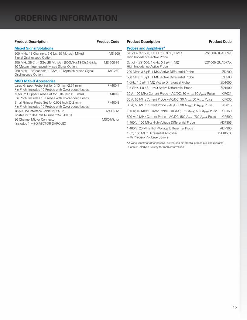
ORDeRING INFORMATION
Product Description Product Code
Mixed Signal Solutions500 MHz, 18 Channels, 2 GS/s, 50 Mpts/ch Mixed MS-500 Signal Oscilloscope Option
250 MHz,36 Ch,1 GS/s,25 Mpts/ch (500MHz,18 Ch,2 GS/s, MS-500-36 50 Mpts/ch Interleaved) Mixed Signal Option 250 MHz, 18 Channels, 1 GS/s, 10 Mpts/ch Mixed Signal MS-250 Oscilloscope Option
MSO MXs-B AccessoriesLarge Gripper Probe Set for 0.10 Inch (2.54 mm) PK400-1 Pin Pitch. Includes 10 Probes with Color-coded Leads Medium Gripper Probe Set for 0.04 Inch (1.0 mm) PK400-2 Pin Pitch. Includes 10 Probes with Color-coded LeadsSmall Gripper Probe Set for 0.008 Inch (0.2 mm) PK400-3 Pin Pitch. Includes 10 Probes with Color-coded Leads 18-pin 3M Interface Cable MSO-3M MSO-3M (Mates with 3M Part Number 2520-6002)36 Channel Mictor Connector MSO-Mictor (Includes 1 MSO-MICTOR-SHROUD)
Product Description Product Code
Probes and Amplifiers*Set of 4 ZS1500, 1.5 GHz, 0.9 pF, 1 MΩ ZS1500-QUADPAK High Impedance Active Probe
Set of 4 ZS1000, 1 GHz, 0.9 pF, 1 MΩ ZS1000-QUADPAK High Impedance Active Probe
200 MHz, 3.5 pF, 1 MΩ Active Differential Probe ZD200
500 MHz, 1.0 pF, 1 MΩ Active Differential Probe ZD500
1 GHz, 1.0 pF, 1 MΩ Active Differential Probe ZD1000
1.5 GHz, 1.0 pF, 1 MΩ Active Differential Probe ZD1500
30 A; 100 MHz Current Probe – AC/DC; 30 Arms; 50 Apeak Pulse CP031
30 A; 50 MHz Current Probe – AC/DC; 30 Arms; 50 Apeak Pulse CP030
30 A; 50 MHz Current Probe – AC/DC; 30 Arms; 50 Apeak Pulse AP015
150 A; 10 MHz Current Probe – AC/DC; 150 Arms; 500 Apeak Pulse CP150
500 A; 2 MHz Current Probe – AC/DC; 500 Arms; 700 Apeak Pulse CP500
1,400 V, 100 MHz High-Voltage Differential Probe ADP305
1,400 V, 20 MHz High-Voltage Differential Probe ADP300
1 Ch, 100 MHz Differential Amplifier DA1855A with Precision Voltage Source
* A wide variety of other passive, active, and differential probes are also available. Consult Teledyne LeCroy for more information.
WSMXs-B-MSO-MXs-B-DS-29jul13
Customer Service
Teledyne LeCroy oscilloscopes and probes are designed, built, and tested to ensure high reliability. In the unlikely event you experience difficulties, our digital oscilloscopes are fully warranted for three years, and our probes are warranted for one year.
This warranty includes:
• No charge for return shipping
• Long-term 7-year support • Upgrade to latest software at no charge
© 2011 Teledyne LeCroy, Inc. All rights reserved. Specifications, prices, availability, and delivery subject to change without notice. Product or brand names are trademarks or requested trademarks of their respective holders.
Local sales offices are located throughout the world. Visit our website to find the most convenient location.
1-800-5-LeCroy teledynelecroy.com