Embed Size (px)
Citation preview

WAVE-DISK ENGINE CONTROL, SYSTEM DESIGN AND IMPLEMENTATION
By
Eric Tarkleson
A THESIS
Submitted to Michigan State University
in partial fulfillment for the requirements of the degree of
MASTER OF SCIENCE
Electrical Engineering
2013

ABSTRACT
WAVE DISK ENGINE CONTROL, SYSTEM DESIGN AND IMPLEMENTATION
By
Eric Tarkleson
The wave disk engine is a type of internal combustion gas turbine engine invented by Dr.
Norbert Mueller, and Dr. Janusz Piechna and patented in 2009. Unlike a typical automobile
engine which operates as an Otto cycle engine, the wave disk engine operates under the
Atkinson cycle. This can lead to a higher theoretical maximum efficiency. Further the wave disk
engine can be realized with only a single moving part, which can minimize system parasitic
losses. Michigan State University received an Arpa-E grant in 2010 that financed the first major
push in the advancement of the underlying principles and the building of a modest engine
testing facility at Michigan State University’s East Lansing campus.
The test facility features state of the art data acquisition and control equipment. It has
over 500 channels available for monitoring and control. The Test Cell is a blast safe,
environmental controlled room, it has industry standard 3 level E-stop system and has
complete video and audio feedback and recording. The remote control room allows all engine
parameters to be monitored, recorded and controlled. The engine can even be controlled by a
wireless tablet for easy sub-system verification. The intent of this paper is to show the reader
the design and implementation of the wave disk engine control systems. This will cover all
electrical and electromechanical systems from ignition systems to gas flow monitoring and
control, to motor/generator control.

Copyright By ERIC TARKLESON
2013

iv
To my parents, Scott and Jonie. To my grandparents, Beverly and Arlene.
v
ACKNOWLEDGEMENTS
I would like to thank my family first and foremost, for it was their hard work that
allowed me to choose my own path and find and follow my dreams. I would like to thank my
brother Tommy for both being a little brother but also for becoming a best friend. I want to
thank my old roommates and band members, Danny, Brett, and Keith for giving me an outlet
outside of school which allowed me to continue this far and maintain some sort of life outside
of engineering.
Of course I have many professors at MSU to thank. Dr. Mueller, Dr. Peng, Dr. Strengas,
Dr. Wierzba, Dr. Goodman, Dr. Olson, Dr L. Udpa and Dr. S Udpa; you all believed in me and
allowed me to have the amazing experiences that I had through MSU. Also all members of the
turbomachinery lab should be thanked for their help and patience in teaching me about
mechanical engineering and turbomachinery. TJ, Quallman, Blake Gower, Jeremy Phillips, Mike
Varney, Guangwei Sun, Pablo Parraga, Dewashish Prasad, Ashwin Hariban, Raul Quispe,
Rohitashwa Kiran. You all made my work possible through your own hard work.

vi
PREFACE
“Out there things can happen
And frequently do To people as brainy And footsy as you”
Dr. Seuss

vii
TABLE OF CONTENTS
LIST OF TABLES ........................................................................................................................................... viii
LIST OF FIGURES ........................................................................................................................................... ix
1 INTRODUCTION TO THE WAVE-DISK ENGINE PROJECT ........................................................................ 1
1.1 THE CHALLENGE ................................................................................................................................ 3
1.2 WAVE DISK SUBSYSTEMS .................................................................................................................. 4
2 TURBOMACHINERY BACKGROUND ....................................................................................................... 9
2.1 BASIC SHOCKWAVE THEORY ........................................................................................................... 10
2.2 WAVE ROTORS ................................................................................................................................ 11
2.3 POWER EXTRACTION PRINCIPLE ..................................................................................................... 14
3 INITIAL TESTS AND FACILITY DESIGN .................................................................................................. 16
3.1 THE TEST CELL ................................................................................................................................. 18
3.2 THE CONTROL ROOM ...................................................................................................................... 20
3.3 IGNITION ......................................................................................................................................... 22
3.4 MEDIUM SPEED MOTOR/GENERATOR ........................................................................................... 27
3.5 CUSTOM HIGH SPEED PMDC MOTOR ............................................................................................. 34
3.6 ELECTRO/MECHANICAL ACTUATORS AND SENSORS ...................................................................... 38
3.7 ANALOG TO DIGITAL CONVERSION................................................................................................. 40
3.8 HIGH SPEED ACQUISITION SYSTEM ................................................................................................ 42
3.9 VIDEO MONITORING ....................................................................................................................... 47
3.10 SAFETY ............................................................................................................................................. 48
3.11 LABVIEW BASED CONTROL ............................................................................................................. 49
4 OPTICAL WAVE DISK ENGINE TEST CELL ............................................................................................. 52
5 CONCLUSION ....................................................................................................................................... 54
REFERENCES ........................................................................................................................................ 56

viii
LIST OF TABLES
Table 1: Motor properties………………………………………………………………………………………………………..25

ix
LIST OF FIGURES
Figure 1: Wave Disk schematic illustration. (For interpretation of the references to color in this and all other figures, the reader is referred to the electronic version of this thesis) .............................................. 2 Figure 2: Wave-disk control block diagram (from (12)) ................................................................................ 4
Figure 3: Wave Disk Engine Showing multiple spark plugs, temperature and pressure sensors ................. 5
Figure 4: Thingap Motor mounted underneath the wave disk engine ........................................................ 6
Figure 5: fuel and air system ......................................................................................................................... 7
Figure 6: shockwave illustration from sonic aircraft (source wiki) ............................................................. 11
Figure 7: model of comprex wave rotor ..................................................................................................... 12
Figure 8: DAQ block diagram (from (12)) .................................................................................................... 17
Figure 9: test cell pictures south wall showing boxes 1 through 4 ............................................................. 19
Figure 10: Test cell picture of north wall .................................................................................................... 19
Figure 11: Control room computers and test viewing screen .................................................................... 20
Figure 12: Control room electronics workbench ........................................................................................ 21
Figure 13: test cell control and feedback hardware inside the control room ............................................ 22
Figure 14: Ignition system box showing MSD modules and high current power supply ........................... 23
Figure 15: Ignition system schematic ......................................................................................................... 23
Figure 16: 3d model of a 24 channel timing disk sensor ............................................................................ 24
Figure 17: Timing disk rotor and sensor underneath wave-disk engine .................................................... 25
Figure 18: Timing disk rotor coupled to wave-disk shaft ............................................................................ 25
Figure 19: Thingap motor mounted on plate ready for install ................................................................... 31
Figure 20: Thingap physical structure (picture from (10)) .......................................................................... 31
Figure 21: Thigpen rotary subwoofer with voice coil driven adjustable blade angles (from (11)) ............ 33
Figure 22: Motor on dynamometer ............................................................................................................ 35

x
Figure 23: Simulated torque vs. speed curve ............................................................................................. 36
Figure 24: Data acquisition and control cabinet ......................................................................................... 41
Figure 25: Custom pressure transducer assemblies ................................................................................... 43
Figure 26: Transient performance test ....................................................................................................... 44
Figure 27: Motor off, air flow 1000 slm, approx 1000 rpm. ....................................................................... 44
Figure 28: Motor 1000 rpm, air flow 1000 slm, ignition off. ...................................................................... 45
Figure 29: Test with combustion, 900 rpm, transient pressure on left, DC pressure on right ................... 46
Figure 30: Temperature sensors. ................................................................................................................ 47
Figure 31: Temperature profile during ignition event ................................................................................ 47
Figure 32: Labview Control Screen ............................................................................................................. 49
Figure 33: DAQ block diagram .................................................................................................................... 50
Figure 34: Labview VI on I-pad, sitting on wave disk engine ...................................................................... 51
Figure 35: Second WDE test facility with optical access. ............................................................................ 52

1
1 INTRODUCTION TO THE WAVE-DISK ENGINE PROJECT
Michigan State University received a 2.5 million dollar ARPA-E grant in 2010 that
financed the first major push in the advancement of the underlying principles and the building
of a state of the art facility at Michigan State University to test the wave disk engine. The
project was initially scheduled to last two years and planned to build a complete test facility
and develop a 10kW first generation prototype engine.
The wave disk engine is a high speed internal combustion gas turbine engine. It is a
torque producing axial turbo-machine designed to produce torque for conversion to electricity.
This type of engine could provide generated electricity as a range extender or fuel powered
backup for an electric vehicles drive system by generating power to recharge the battery while
at rest, or during operation.
The test engines used during this project are very small, less than .5x.5meters including
the wave disk engine itself and the electric motor/generator used for startup, control, and
power extraction. While our first generation test engines don’t measure up to the full potential,
an engine this small eventually could provide up to 20kW continuously. This type of generator
system would provide a higher power density (output power/ unit size) than is commercially
available.
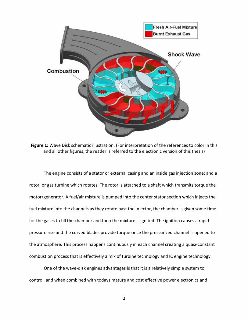
A wave disk engine can be described as a constant volume combustion machine,
utilizing turbomachinery principles. The mini-turbine, compressor and combustor are achieved
in a single rotating turbine/fan blade structure to generate torque. Figure 1 shows a simple
wave disk engine design and describes its combustion process.
2
Figure 1: Wave Disk schematic illustration. (For interpretation of the references to color in this and all other figures, the reader is referred to the electronic version of this thesis)
The engine consists of a stator or external casing and an inside gas injection zone; and a
rotor, or gas turbine which rotates. The rotor is attached to a shaft which transmits torque the
motor/generator. A fuel/air mixture is pumped into the center stator section which injects the
fuel mixture into the channels as they rotate past the injector, the chamber is given some time
for the gases to fill the chamber and then the mixture is ignited. The ignition causes a rapid
pressure rise and the curved blades provide torque once the pressurized channel is opened to
the atmosphere. This process happens continuously in each channel creating a quasi-constant
combustion process that is effectively a mix of turbine technology and IC engine technology.
One of the wave-disk engines advantages is that it is a relatively simple system to
control, and when combined with todays mature and cost effective power electronics and

3
automotive technology, results in an integrated generation system with many advantages over
traditional technologies. In fact it may benefit from reduced cost and cheaper control than
traditional automotive engines because the design inherently has a low number of rotating
parts, which significantly reduces machining and production costs.
1.1 THE CHALLENGE
While the first prototype of a wave-disk engine was being designed and manufactured, a
complete test cell needed to be designed and built to allow testing this brand new technology.
Since this was a relatively short term project, two years, and low budget, 2.5 million USD, it was
imperative to be able to begin testing the prototypes as soon as possible.
The test cell was designed and built in under six months. The facility features state of
the art data acquisition and control equipment. It has a virtually unlimited number of input and
output channels available for monitoring and control, due partially to its highly reconfigurable
nature. The completed wave-disk test facility consists of a gas storage room, a test cell, a
control room, and an outside courtyard housing exhaust fan and cooler compressors. The test
cell is a blast safe, environmental controlled room, it has a 3 level E-stop system and controls
designed to protect the operators. Both test cell and control room have complete video and
audio feedback and recording. The remote control room allows all engine parameters to be
monitored, recorded and controlled simultaneously in real time. The engine can even be
controlled by a wireless tablet for easy sub-system testing and verification. The intent of this
paper is to show the reader the design and implementation of the wave disk engine control
systems as well as the implementation of the entire project. This will cover all electrical and

4
electromechanical systems from ignition systems to gas flow monitoring and control, to
motor/generator control. Figure 2 describes the overall system layout.
Figure 2: Wave-disk control block diagram (from (1))
1.2 WAVE DISK SUBSYSTEMS
The wavedisk engine is completely controlled via electric control systems controlling
electro-mechanical actuators and sensors. There is an ignition system, fuel and airflow systems,
motor/generator and their associated controllers, environmental feedback such as temperature
sensors, speed sensors and pressure sensors and. All of this is controlled via National
Instruments Compaq DAQ series data acquisition systems. All programming is in Labview, a
PC
Ethernet
CompactDAQSystem
2x NI-9188
EIP VFD
PMDC Motor Controller
Pressure Transducers
Temperature Sensors
Ignition Control Relay
Mass Flow Controllers

5
visual programming environment which excels in parallel data processing such as is required
when many variables must be monitored and controlled simultaneously.
Figure 3: Wave Disk Engine Showing multiple spark plugs, temperature and pressure sensors
Proper Ignition of fuels in the wave disk engine was a large obstacle in running the first
prototype. Several design iterations have produced several highly reliable and well controlled
systems that have very good ignition characteristics. See Figure 3.
A motor/generator is a critical component in the wave disk engine. The motor will first
act as a starter, spinning the engine up to its intended operating speed. After combustion
begins the engine starts producing torque and the motor begins acting as a generator as the
motor torque becomes negative. The two components are coupled directly to each other by a

6
stiff shaft. Two workhorse PMDC motors are used to fulfill all of these requirements. See figure
4.
Figure 4: Thingap Motor mounted underneath the wave disk engine
In order to achieve fine control of all system parameters in the wave-disk engine a wide
array of sensors were purchased according to the type of tests that needed to be performed.
This posed a challenge because the test cell needed to be able to accommodate a huge array of
different tests, under different wave-disk designs. All of this while still providing test and sensor
flexibility has resulted in an extremely capable and reconfigurable test environment while still
being safe and easy to learn and operate.

7
All gas, air and fluid flow in and out of the engine is controlled and monitored to allow
testing the engine under a wide variety of operating conditions. The system has the ability to
use virtually any type of compressed gas including ethane, methane, and hydrogen and only
small modification are needed if liquid fuels were to be tested in the engine. See figure 5.
Figure 5: fuel and air system
High quality pressure data is important in virtually every engine or turbine test
environment and the wave-disk engine is no different. The prototype design allows for pressure
taps to be located directly on the engine housing and can be moved to an almost unlimited
number of locations due to the top stator plates design. This data gives us important insights
into the combustion process inside the engine and helps to provide data to match with
simulated engines also developed at MSUs turbomachinery laboratory.

8
Like pressure data, temperatures inside the engine are important for proper engine
characterization and validation and the test cell features a large array of different technologies
to match any test requirement.
The environment of the engine and test cell provided a challenging environment to
obtain accurate electrical measurements from the various sensors. The motors are high voltage
PMDC motors which can cause significant EMF interference near their windings which can
couple into the engine housing and from there onto the instrumentation. The ignition system is
designed to provide over 40k Volts during a very short intervals. This makes for extremely
energy dense EMC pulses that have actually been measured outside of the room. However,
proper wiring and labview programming practices have effectively mitigated these artifacts in
most of the sensing equipment.
The following chapters will describe the mechanical operating principles and well as
electronic control and data acquisition in more detail. Further, actual test results will prove the
power and flexibility of this system.

9
2 TURBOMACHINERY BACKGROUND
The wave disk engine is a high speed internal combustion gas turbine engine. It is a
torque producing axial turbo-machine designed to produce torque for conversion to electricity.
A wave disk engine can be described as a constant volume combustion machine, utilizing
turbomachinery principles. The mini-turbine, compressor and combustion chamber are
achieved in a single rotating part to generate torque for transmission to power (2) . Unlike a
typical an automobile engine which operates as an Otto cycle engine, the wave disk engine
operates under the Brayton cycle. This can lead to a higher theoretical maximum efficiency.
Further since the wave-disk engine can be realized with only a single moving part, instead of
hundreds as a modern IC engine has, the design inherently minimizes system parasitic losses (3)
due to mechanical friction. The wave disk engine can be described as a axial, interior inlet
configuration of a wave rotor, where the rotor is designed to produce torque instead of
compression, which is typically used as a 2 or 4 port compression device. Wave rotors will be
explained in the next section
A unique feature of the wave disk engine, especially compared to traditional IC engines
is that it is designed to run only at its most efficient operating point. A traditional IC engine is
designed to produce usable torque over a large range of speeds. The wave disk engine,
however, is easily configured as a constant power generator, meaning that its output power
does not depend on the total system load. The engine would be turned on for battery charging
in a serial hybrid car and generate maximum power, and then turned off once the batteries are
fully charged. This means fuel is never wasted during idling. In a traditional IC engine the power
output is constantly changing depending on the torque and speed required by the user,
10
because of this the engine almost never runs at its most efficient operating point. Also the
maximum efficiency the engine could be designed for must be compromised in order for the
engine to be reasonably efficient over its entire speed range. This is also the same scenario as in
a typical IC engine generator, such as used for emergency backup power in homes and
businesses. The load and power requirement depend on the current which must be supplied in
order to maintain the AC voltage. These IC generators typically have an output power
proportional to the load of the electrical side.
2.1 BASIC SHOCKWAVE THEORY
The wave disk engine is designed to take advantage of unsteady flow phenomoma in
order to enjoy increased efficiencies in its thermodynamic cycle. Unsteady flow phenomena has
historically been viewed as a detriment to turbomachinery. Shock waves and other transient
effects cause unwanted and unpredictable vibrations, decreasing the life of most rotating
machinery. However some have studied this effect and found ways to use shockwaves as an
added advantage (4). A wave rotor is a type of compression device which caused pressure
increase by utilizing shockwave principles.
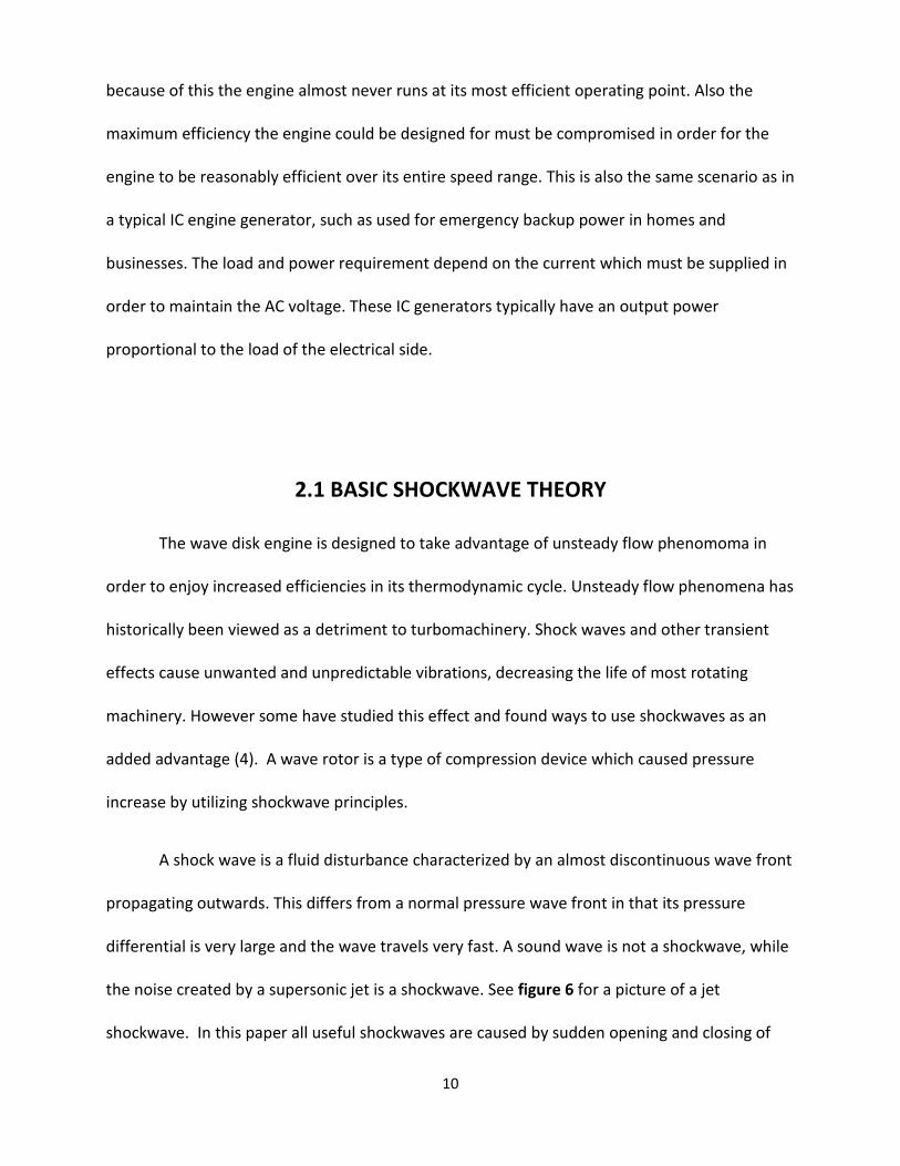
A shock wave is a fluid disturbance characterized by an almost discontinuous wave front
propagating outwards. This differs from a normal pressure wave front in that its pressure
differential is very large and the wave travels very fast. A sound wave is not a shockwave, while
the noise created by a supersonic jet is a shockwave. See figure 6 for a picture of a jet
shockwave. In this paper all useful shockwaves are caused by sudden opening and closing of
11
the channels inlet and outlet ports of the wavedisk engine. Since a shockwave travels much
faster than a traditional pressure wave-front and has a very high pressure differential between
ambient pressure and the wave-front, this phenomenon may be used for compression of fluids
(5).
Figure 6: Shockwave illustration from sonic aircraft (from Wikipedia)
2.2 WAVE ROTORS
Wave Rotors use rapid openings and/or closings of ported channels to generate
shockwaves which propagate away from the port. The Wave rotor is typically constructed as an
axial flow device with many small channels in a cylindrical tube as seen in figure 7. The inlet and

12
outlet ports are seen before and after the rotor and are timed to allow the wave to travel the
port length exactly when the port is opened. The channel is closed immediately after the wave
passes through. This leaves a high pressure area in the outlet port of the wave rotor and a low
pressure zone in the rotating port.
Figure 7: model of comprex wave rotor
The wave-disk engine is like a wave rotor with several important differences. First it is
configured as an axial-turbo machine with inlet in the interior and outlet on the outside. This
orientation is advantageous because scavenging, compression and aspiration is helped by the
centrifugal forces created from the disks rotation. Further the wave disk engine has curved
interior channels which are optimized for torque production instead of compression. Finally the
current wave disk engine uses the interior channels for the combustion chamber as well as the
turbo-fan, this makes the whole engine smaller (less a separate combustion chamber) and has
some of the advantages gained by a constant volume combustion, as in a traditional IC engine
(6). This leads to a higher power to weight ratio than turbine engines.
13
The engine is tuned so that the opening of the inlet port creates a shockwave which
travels towards the outside of the engine. This can pre-compress the fuel mixture before
combustion, leading to more powerful and faster combustion. It is even possible that a very
large shockwave could compress and ignite the fuels if the engine casing was hot enough. This
would mean that a traditional ignition system may not be needed after the engine is heated.
This eliminates all losses stemming from the ignition system.
The only current commercially available shock wave compressor is called the “Comprex
wave rotor”. The comprex has been successfully used in the Mazda 626 Cappela model in place
of a turbocharger. Michigan State University has been working with unsteady flow devices since
1991. The Turbomachinery lab built several test rigs to examine wave rotor technology
between 2006 and 2008. This research is what led to the invention of a new wave rotor
configuration designed for torque production instead of compression, the Wave-Disk Engine.
Michigan State University has built two test rigs for the comprex wave rotor. The author
built the data acquisition and test sequences for both test rigs. Dr Piechna and Dr. Mueller did
an investigation into new uses for wave rotor technology (4) and found several interesting
design topologies which promise unique and exciting advantages over current unsteady flow
devices as well as applications in modern IC engine. This led to the invention of the “wave-disk
engine”, which successfully combines the separate components of a traditional multi-stage
turbo-machine, as well as integrating some components of IC engines, leading to a combustion
engine with only 1 moving part. In addition the motor may be tuned carefully to utilize
shockwaves to enhance the engine efficiency even further by aiding in pre-compression before
combustion. (6)

14
2.3 POWER EXTRACTION PRINCIPLE
The wave-disk engines thermal cycle may be described by the Brayton cycle. A standard
Brayton cycle engine has three main components; a compressor, a combustor, and a turbine.
The wave disk engine combines these components into a single part. It can also be argued to
operate under the Aktinson cycle, because instead of having constant combustion such as in a
Brayton cycle engine the wave-disk has quasi-confined combustion if it is tuned to burn
completely before the chamber is open to exhaust. In order for this to be true the engine must
have very tight tolerances and low airgaps once it is heated up to operating temperature. A gas
and air mixture is injected directly into the turbine, the large centrifugal forces from inertia help
to compress the mixture, and then the mixture is ignited causing rapid pressure and
temperature rise, the turbine is able to extract this energy in the form of rotational torque.
Equations 1-3 describe the power extraction principle. As the turbine generates torque the total
mechanical power generated depends on the rotational speed and the torque developed by the
combustion process.
𝑃𝑚𝑒𝑐ℎ = 𝜔 ∗ 𝜏 Equation 1
The speed is dependent on the relationship between the torque produced by the engine
and the motor. The power the motor is able to convert from mechanical to electrical power
depends on its efficiency at that operating point (speed, current).
𝑃𝑒𝑙𝑒𝑐 = 𝑉 ∗ 𝑖 Equation 2

15
𝑃𝑒𝑙𝑒 = 𝑃𝑚𝑒𝑐ℎ ∗ 𝐸𝑚𝑜𝑡𝑜𝑟𝐸𝑓𝑓𝑖𝑐𝑖𝑒𝑛𝑐𝑦 Equation 3
This shows how the electrical power generated depends on a relationship between the
torque produced by the engine and the negative torque produced by the electric motor. The
balance that insures maximum power transfer is discussed in detail in following chapters.
A wave disk engine operates most efficiently at high speeds and temperatures. The
torque produced by a wave disk engine is relatively small and its speed very high when
compared to today’s IC automobile engines. This makes it difficult to couple the engine to
traditional mechanical systems in vehicles, ie wheels. Therefor this engine is suitable for
conversion from mechanical to electrical power using a high speed PMDC or reluctance motor.
Modern high speed motors have a high efficiency, currently up to 90%. In a vehicle the
electrical power can charge batteries for an electrical drivetrain. Also this design could be used
for small to medium scale power generation.
When compared to todays IC engines like those used in automobiles and small scale
power generation; the wave disk engine has many advantages. It is small (high power to weight
ratio) meaning that it can be cheaper and use less space than a similar power output IC engine;
it has a single moving part making it easier to build, troubleshoot and fix, and it can easily be
modified for small scale power generation as well as automobile power trains.

16
3 INITIAL TESTS AND FACILITY DESIGN
Initially wave disk testing was performed at the engine research lab (ERL) @ MSUs
research facility. But it was apparent there was a need for a separate test cell designed
specifically for the wave-disks unique design. So in October 2010 the turbomachinery
laboratory was given two small unused rooms, part of a compressed gas storage area, and an
exterior courtyard in the engineering building. One room was designated as a control room, the
other was turned into a combustion safe test cell. The test cell consists of a blast door; designed
to vent an explosion and gases into the locked courtyard in the case of a massive fault, two air
exchange systems, 4500 and 600 CFM used for exchanging exhaust gases with fresh air, a fluid
cooling system, gas and air supplies and an environmental monitoring system with fully
automatic shutdown in the case of dangerous levels of C02, hydrogen ethane or methane.
Emergency stop switches were installed both inside and outside the area. This work insured the
room was safe and to code before the turbo lab began installing its own equipment. The
outside courtyard also hosts the large fans and cooler equipment.
The author was in charge of the system design and implementation of the test cell and
control room hardware, software, implementation and management. The MSU physical plant
installed the room piping, fans, coolers, gas lines and some of the safety instrumentation
systems under the supervision of the author. During this time the initial acquisition and control
wiring was being built, tested and installed in the turbomachinery work area.
17
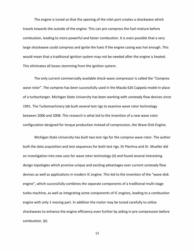
As with any electromechanical system the wave disk engine must be controlled
properly. This includes controlling all inputs and outputs of the entire system including air flow,
gas flow, speed, torque, power output, temperature, internal pressures and ignition among
others. The wave-disk engine test cell monitors, records, calculates and controls all data being
used for any test in real-time. The system is designed so that all data is recorded so none is ever
lost. The system is fast enough that there is almost instantaneous feedback from the data
acquisition system if any variables are changed. Figure 8 shows a simplified diagram of the
Wave Disk System and its input/output scheme.
Figure 8: DAQ block diagram (from (1))

18
3.1 THE TEST CELL
The test cell is designed for safely testing the wave-disk engine while lending itself
towards quick changes and ease of equipment access to facilitate numerous types of testing.
Even though it is a small area compared to many engine testing facilities it houses everything
needed for every type of test the lab could conceive and also has room for future expansion.
6 enclosures were installed in order to safely house the various electrical and
mechanical systems needed for running the prototype wave-disk engines. These are shown in
Figures 9 - 10. Box 1 is a power box allowing power supplies to be mounted away from sensitive
sensors and data acquisition and control equipment, box 2 houses all ignition equipment, box 3
is the data acquisition box, it is a DC power only box to prevent unnecessary noise, and box 4 is
available for future expansion. On the opposite wall, a smaller box, 5, houses different pressure
sensors for various purposes and larger box 6 houses flow controllers for the various air and gas
lines.

19
Figure 9: test cell pictures south wall showing boxes 1 through 4
Figure 10: Test cell picture of north wall
20
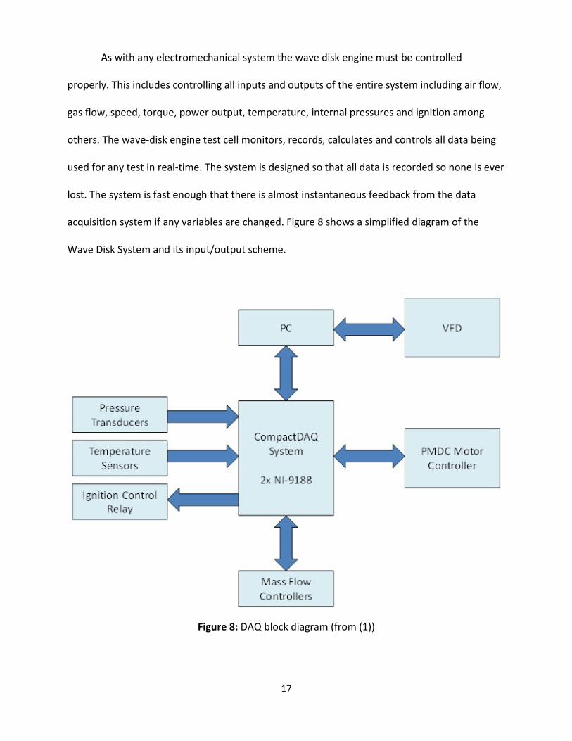
3.2 THE CONTROL ROOM
The control room is located a short distance away from the test cell. It houses several
computers for control and storage, a large TV to view tests in action, VFD and control hardware
for the test cells climate control, air evac, and water chiller systems as well as a small
electronics work bench. See figures 11 and 12.
Figure 11: Control room computers and test viewing screen

21
Figure 12: Control room electronics workbench
A small Ethernet network connects all labview hardware, motor controllers, video and
audio feedback between the two rooms. The network is isolated for safety and speed, insuring
no outside network traffic impedes the data flow between the various systems. Hardwired
Estop controls have dedicated and redundant controls for maximum safety.
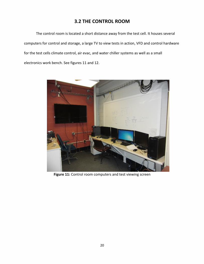
All controls for the air exchangers, fluid cooling system, environmental safety and test
cell power are located in the control room for quick access and control. Figure 13 shows the
components situated along the wall behind the data acquisition computers.
22
Figure 13: test cell control and feedback hardware inside the control room
3.3 IGNITION
The ignition system must be controlled to have the ability to spark at exactly the same
position in each channel as the individual channels rotate inside the engine casing. This allows
for the consistent combustion therefor leading to the most efficient and continuous
combustion.
The electric ignition system is composed of a low voltage, 13.5V, high current, 100 amp
power supply, a boost converter, a medium voltage bus and a triggering circuit connected to a
high voltage transformer. See figure 14 for a view of the actual system and figure 15 for a
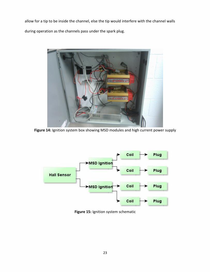
simplified schematic. The spark plugs themselves are tip-less because the channel walls don’t
23
allow for a tip to be inside the channel, else the tip would interfere with the channel walls
during operation as the channels pass under the spark plug.
Figure 14: Ignition system box showing MSD modules and high current power supply
Figure 15: Ignition system schematic
24
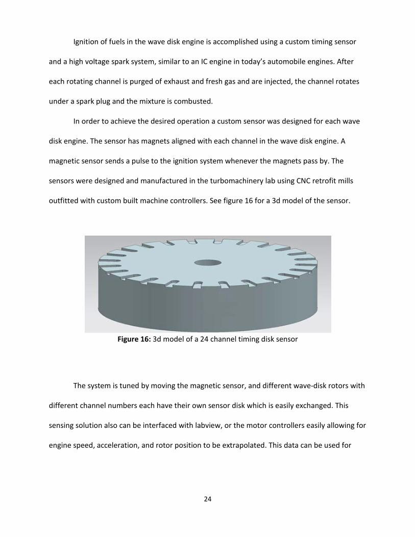
Ignition of fuels in the wave disk engine is accomplished using a custom timing sensor
and a high voltage spark system, similar to an IC engine in today’s automobile engines. After
each rotating channel is purged of exhaust and fresh gas and are injected, the channel rotates
under a spark plug and the mixture is combusted.
In order to achieve the desired operation a custom sensor was designed for each wave
disk engine. The sensor has magnets aligned with each channel in the wave disk engine. A
magnetic sensor sends a pulse to the ignition system whenever the magnets pass by. The
sensors were designed and manufactured in the turbomachinery lab using CNC retrofit mills
outfitted with custom built machine controllers. See figure 16 for a 3d model of the sensor.
Figure 16: 3d model of a 24 channel timing disk sensor
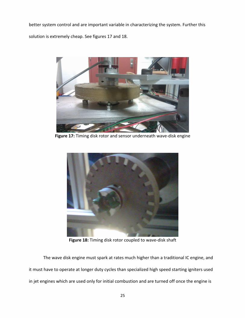
The system is tuned by moving the magnetic sensor, and different wave-disk rotors with
different channel numbers each have their own sensor disk which is easily exchanged. This
sensing solution also can be interfaced with labview, or the motor controllers easily allowing for
engine speed, acceleration, and rotor position to be extrapolated. This data can be used for
25
better system control and are important variable in characterizing the system. Further this
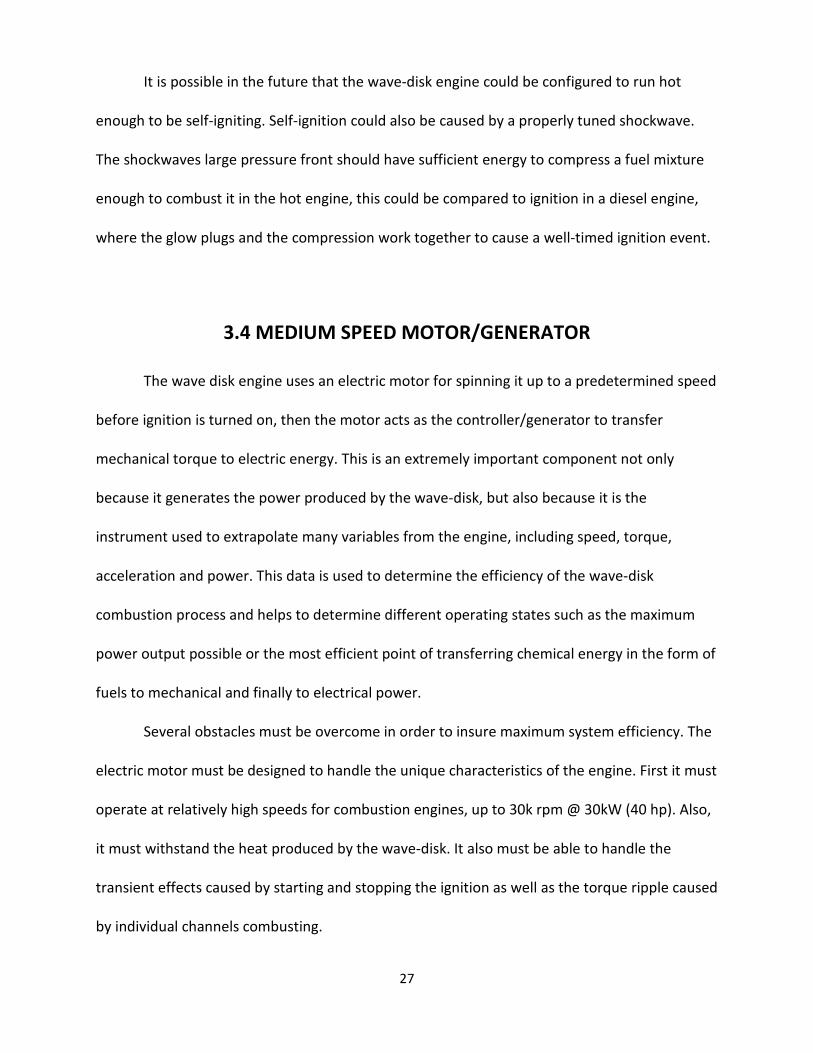
solution is extremely cheap. See figures 17 and 18.
Figure 17: Timing disk rotor and sensor underneath wave-disk engine
Figure 18: Timing disk rotor coupled to wave-disk shaft
The wave disk engine must spark at rates much higher than a traditional IC engine, and
it must have to operate at longer duty cycles than specialized high speed starting igniters used
in jet engines which are used only for initial combustion and are turned off once the engine is

26
self-igniting. The timing and ignition system is a mix between traditional ignition technology
and variations on other types of control systems to realize.
In a traditional IC engine or generator a timing belt or disk controls each cylinders spark
plug telling it when to fire. The sparking rate (x) is related to the speed of the engine.
𝑥 (ℎ𝑧) =2 ∗ 𝑅𝑃𝑀
60 Equation 4
A wave disk engine operates much faster, a relationship between its rotational speed
(ω), channels(c), and firing rate(x) is
𝑥 (ℎ𝑧) =𝜔 ∗ 𝑐
60 Equation 5
For instance, for a WDE with 32 channels rotating at a speed of 10,000 rpm, a spark plug
must fire at a rate of 5.33 kHz to fire once per channel. This represents a large departure from
current technology where a typical 4 cylinder 4 stroke automobile engine runs around 4000
rpm, or sparks at a rate of only 8000 sparks/minute or 133 Hz.
As the speed of a commercially available ignition continues past its maximum
specifications, the energy in the spark decreases because the capacitor (and/or inductor)
cannot fully charge before the next spark.
High-speed, high-voltage ignitions are well within our current capabilities to design but
cannot be easily purchased because there is no market for this type of ignition. Therefor the
wavedisk engine uses a top of the line MSD ignition which works up to approximately 10k RPM.
For speeds higher than this a new custom ignition must be designed and built.
27
It is possible in the future that the wave-disk engine could be configured to run hot
enough to be self-igniting. Self-ignition could also be caused by a properly tuned shockwave.
The shockwaves large pressure front should have sufficient energy to compress a fuel mixture
enough to combust it in the hot engine, this could be compared to ignition in a diesel engine,
where the glow plugs and the compression work together to cause a well-timed ignition event.
3.4 MEDIUM SPEED MOTOR/GENERATOR
The wave disk engine uses an electric motor for spinning it up to a predetermined speed
before ignition is turned on, then the motor acts as the controller/generator to transfer
mechanical torque to electric energy. This is an extremely important component not only
because it generates the power produced by the wave-disk, but also because it is the
instrument used to extrapolate many variables from the engine, including speed, torque,
acceleration and power. This data is used to determine the efficiency of the wave-disk
combustion process and helps to determine different operating states such as the maximum
power output possible or the most efficient point of transferring chemical energy in the form of
fuels to mechanical and finally to electrical power.
Several obstacles must be overcome in order to insure maximum system efficiency. The
electric motor must be designed to handle the unique characteristics of the engine. First it must
operate at relatively high speeds for combustion engines, up to 30k rpm @ 30kW (40 hp). Also,
it must withstand the heat produced by the wave-disk. It also must be able to handle the
transient effects caused by starting and stopping the ignition as well as the torque ripple caused
by individual channels combusting.

28
The motors chosen for wave disk control are both permanent magnet Direct Current
(PMDC) motors. This type of motor uses a 3-phase stator winding and high strength permanent
magnets in the rotor for torque production. This type of electric motor is becoming more
common despite its usually higher price due to its high power density, reliability, and ability to
achieve very good control.
For comparison purposes with traditional IC engines, an equation which describes the
relationship between horsepower and kilowatts is.
1ℎ𝑝 = 746𝑊𝑎𝑡𝑡𝑠 Equation 6
The electric motor should have its efficiency peak at the engines rated speed and torque
to insure maximum power transfer from mechanical to electrical power. The equations below
explain the relationship between torque and motor voltage inside of a PMDC motor such as
used for both electrical motor/generators in the wave disk engine. V is terminal to terminal
voltage between any two phase legs, R is stator resistance, L and M are terminal and mutual
inductance, respectively; p is # of pole pairs, I is current, and E is the back EMF created by the
machine during operation.
𝑉𝑥𝑠 = 𝑅𝑠 ∗ 𝐼𝑥𝑠 + (𝐿 −𝑀)𝑝 ∗ 𝐼𝑥𝑠 + 𝐸𝑥𝑠 Equation 7
The next equation shows torque created where T is torque, I is current w is speed and e
is an equation that relates the voltage waveform supplied by the controller.

29
𝑇𝑒(𝑁𝑚) = (𝑒𝑎𝑠𝑖𝑎𝑠 + 𝑒𝑏𝑠𝑖𝑏𝑠 + 𝑒𝑐𝑠𝑖𝑐𝑠)1𝜔𝑚
Equation 8
The motors electrical control system (motor drive, vfd, inverter) needs also to be
matched for maximum power transfer at the intended operating speed. For this it is imperative
to understand the mechanical losses and system behavior when the PMDC motor is coupled
directly to the wave disk engine. Here J is system inertia, wm is speed, B is the friction
coefficient, and B*wm represents the power lost due to mechanical friction, Tl is load torque,
or the torque produced by the wave-disk engine, Te is electromagnetic torque which may be
positive or negative depending on whether the system is in motoring or generation mode.
𝐽𝑑𝜔𝑚𝑑𝑡
+ 𝐵𝜔𝑚 = (𝑇𝑒 − 𝑇𝑙) Equation 9
Accurately recording power transfer was a challenge during testing the wave disk
engine. First, between disciplines there can be ambiguity as to where the power is measured
and what type (electrical or mechanical) of power it represents. Consider the following
example. The motor is 90% eff, the VFD (variable frequency drive) is 90% and the power the
motor is generating from the wave-disk engine is 100 watts. Only the 100 watts obtained from
the VFD is useful for power generation. The actual mechanical power produced by the system is
below.
𝑃𝑚𝑒𝑐ℎ =100𝑊. 9 ∗ .9
= 123.4𝑊 Equation 10
This example shows how important power transfer between components is. Even when
operating near todays limits for well-designed systems almost ¼ of the power produced is lost

30
during transfer. This is why it is important to insure that the motor is designed to be most
efficient at the same speed and torque as the wave-disk engine. Further this example does not
take into account losses stemming from the combustion process, such as heat losses, unburned
fuel, and losses from non-ideal sealing inside the engine.
A last critical design variable that must be taken into account is the temperature of the
motor and its environment. The permanent magnets in PMDC motors (or any magnets) can be
demagnetized if they are heated past their demagnification point. To reduce total wave-disk
system size it is desirable to place the motor close as close as possible to the engine, this also
leads to a shorter shaft, better power transfer, less shaft vibrations, and ultimately better
control. However, the wave-disk engine is designed to have case temperatures in excess of 300
degrees Celsius. This temperature is detrimental to any motor, especially modern DC motors,
whose magnetic materials tend to be very susceptible to heat.
Together these challenging requirements fit a specific type of motor design well. It is
called a “ducted fan motor” or a “ring motor” and has been developed, by Thingap Corporation
(7). See figures 19 and 20. In theory a ring motor is a permanent magnet Brushless DC machine
but its construction is so novel this is not immediately apparent. A ducted fan motor has a very
unique mechanical design where the motor structure itself is a large diameter ring and it is
attached to a shaft in the center. This design is low loss because the magnetic circuit is low loss,
it consists of a U shaped steel ring that wraps around the magnets making for a short magnetic
path and small air-gap; it is self-cooling because there is little bulk iron to build up heat and the
air turbulence near the copper quickly removes heat buildup from the winding structures (7),
finally the physical separation from the shaft isolates the hot engine from heating up the
electric motor while still taking up less vertical space than a typical motor. A motor like this also
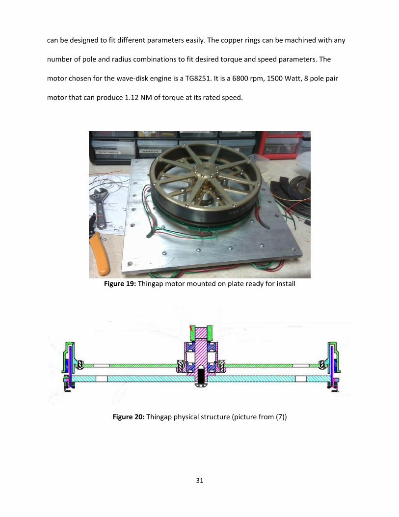
31
can be designed to fit different parameters easily. The copper rings can be machined with any
number of pole and radius combinations to fit desired torque and speed parameters. The
motor chosen for the wave-disk engine is a TG8251. It is a 6800 rpm, 1500 Watt, 8 pole pair
motor that can produce 1.12 NM of torque at its rated speed.
Figure 19: Thingap motor mounted on plate ready for install
Figure 20: Thingap physical structure (picture from (7))

32
This motor is controlled using an Advanced Motion Control B100A40AC analog motion
control drive. Because it is an analog drive it has a very fast transient response when tuned
properly. This type of motor controller is good for use in a testing environment because it is
very versatile, however a knowledge of PID loops and analog controls is required to get
maximum performance from this controller.
The wave-disk engine coupled with a thingap or other type of ring motor is a unique
configuration which leads to a novel method for integrating multiple system components into
the motor/generator assembly. For example, instead of straight stator rings from the outside of
the motor to the shaft, a fan structure could be inserted. This could be a cooling feature for the
engine, an inlet airflow supercharger or both!
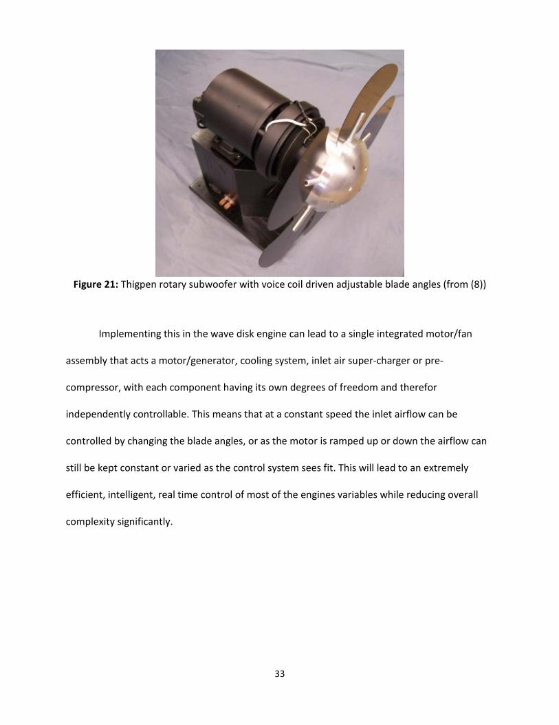
Several novel designs exist for motors with blades whose angle can be electrically
controlled during operation (8), See figure 21. The Thigpen rotary subwoofer is a motor
controller fan whose blades angles are controller via a voice coil, like in a speaker cone.
33
Figure 21: Thigpen rotary subwoofer with voice coil driven adjustable blade angles (from (8))
Implementing this in the wave disk engine can lead to a single integrated motor/fan
assembly that acts a motor/generator, cooling system, inlet air super-charger or pre-
compressor, with each component having its own degrees of freedom and therefor
independently controllable. This means that at a constant speed the inlet airflow can be
controlled by changing the blade angles, or as the motor is ramped up or down the airflow can
still be kept constant or varied as the control system sees fit. This will lead to an extremely
efficient, intelligent, real time control of most of the engines variables while reducing overall
complexity significantly.

34
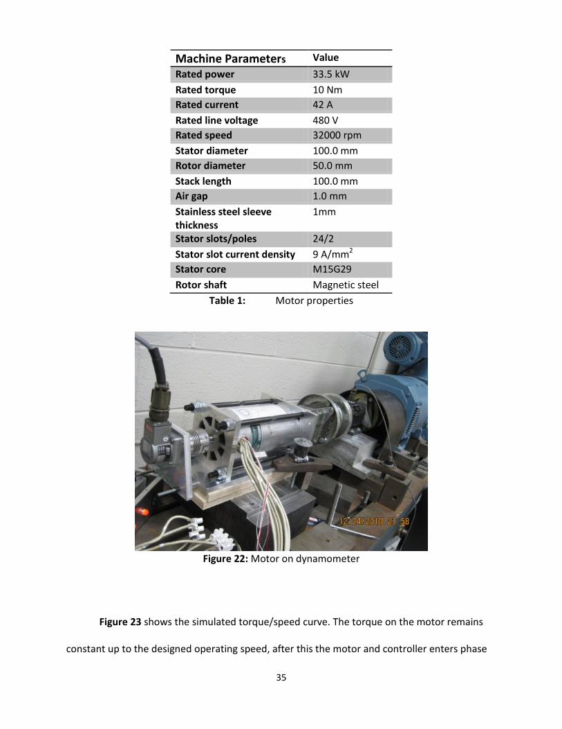
3.5 CUSTOM HIGH SPEED PMDC MOTOR
The Thingap TG8251 motor is very suitable for low speed testing under 10k rpm,
however the wave disk engine may operate at speeds up to 30k rpm. For this purpose the
Electrical Machines and Drives research group @ Michigan State University designed and built a
2 pole high speed 30kW permanent magnet machine to drive the engine to speeds up to 30k
rpm. Table 1 shows machine parameters, Figure 22 shows a picture of the motor on a
dynamometer. Samarium Cobalt was chosen as the permanent magnet material instead of the
more often used neodymium because samarium cobalt can withstand higher temperatures
before demagnification.
35
Machine Parameters Value Rated power 33.5 kW Rated torque 10 Nm Rated current 42 A Rated line voltage 480 V Rated speed 32000 rpm Stator diameter 100.0 mm Rotor diameter 50.0 mm Stack length 100.0 mm Air gap 1.0 mm Stainless steel sleeve thickness
1mm
Stator slots/poles 24/2 Stator slot current density 9 A/mm2 Stator core M15G29 Rotor shaft Magnetic steel
Table 1: Motor properties
Figure 22: Motor on dynamometer
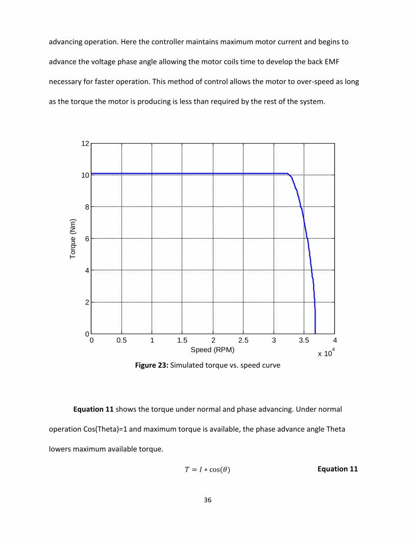
Figure 23 shows the simulated torque/speed curve. The torque on the motor remains
constant up to the designed operating speed, after this the motor and controller enters phase
36
advancing operation. Here the controller maintains maximum motor current and begins to
advance the voltage phase angle allowing the motor coils time to develop the back EMF
necessary for faster operation. This method of control allows the motor to over-speed as long
as the torque the motor is producing is less than required by the rest of the system.
Figure 23: Simulated torque vs. speed curve
Equation 11 shows the torque under normal and phase advancing. Under normal
operation Cos(Theta)=1 and maximum torque is available, the phase advance angle Theta
lowers maximum available torque.
𝑇 = 𝐼 ∗ cos (𝜃) Equation 11
0 0.5 1 1.5 2 2.5 3 3.5 4
x 104
0
2
4
6
8
10
12
Speed (RPM)
Torq
ue (N
m)

37
Phase advancing on the wave disk engine would only be used during testing and design
because phase advancing limits the torque and therefor the power the motor is capable of
producing and generating. A production wave-disk/motor/generator would be designed to
produce maximum power without the motor moving into phase advancing operation.
This motor was designed, by Tariq Abdul under the direction of Dr Strangas. However
the control system for the motor had to be custom designed for the motor and the wave disk
engine. To accomplish this task a Yaskawa A1000 drive was purchased. This drive can operate
up to 400hz, significantly higher than standard digital servo drives, in fact higher speed drives
require goverment approval because of their possible use in uranium enrichment. This insures
that high speeds can be reached even if another motor with higher pole count, such as the
Thingap TG8251 is used. This drive is a robust digital drive designed for industry applications.
The high speed digital control insures better transient response at normal operating speeds,
however, the PID loops and motor parameters must be tuned carefully to insure short settling
time and rapid response as the wave disk begins generating torque. The drive can operate the
motor under sensorless control algorithms built into the drive. However the motor also was
tested with a position sensor for better transient control. This motor has allowed some high
speed testing of the Wave disk engine assembly allowing testing for structural stability.

38
3.6 ELECTRO/MECHANICAL ACTUATORS AND SENSORS
Electro-mechanical actuators, controls, and sensors are a mature technology that has
found wide use throughout all aspects of industry and especially in the automotive industry.
However, in a new engine design it still is pertinent to point out the specific uses and design
considerations for the necessary actuators and controls.
All gas/fluid flow in and out of the engine is controlled and monitored to allow testing
the engine under a wide variety of operating conditions. This starts with the inlet, both air and
fuel must be controlled precisely. This is accomplished with several 500 and 1500 CFM air flow
controllers. Several controllers with different ranges were purchased in order to accomplish
well-tuned control over the whole operating range.
The fuel system operates similar to the air inlet system. The fuel may be liquid, but the current
wave disk engines operate on compressed gaseous fuels, such as ethane, methane, and
hydrogen. For liquid fuels a gas pump will be necessary, for current gaseous fuels, a flow
controller regulates the fuel flow between the engine and the compressed tank. Both the gas
and air systems work together to maintain a constant mix of gas/air into the intake of the
engine. The ratio can be computer controlled and adjusted for maximum power or maximum
efficiency. The air and gas is injected into the inlet at the center after being mixed in a mixing
tube. Gas can also be injected directly into the channels if desired to achieve a more controlled
injection right before combustion.
The Gas is controlled by smaller 20CFM and 50CFM flow controllers. They were chosen
to fit the flow ranges required by the wavedisk engine, taking into account the different types

39
of fuels being tested. They are all controlled via the labview interface and also have a feedback
signal to check for actual vs, controlled flow. Each controller can be turned off and bypassed if it
is not being used. Each of these controllers has independent PID controls and digital logic
allowing the user to select the gas and tune the controller for the accurate response. This
allows for quick gas changover because the PID systems built into labview do not need to be
changed for different controllers or gases. They are controlled and monitored via a labview
programming insuring consistent air/fuel ratios, which can be changed at the touch of a button.
The resulting gas/air delivery system is both intuitive and powerful.
Several pressure transducers monitor the pressure to record pressure variations as well
as pressure loss throughout the system.
Outlet pressure and flow is not currently monitored because the wave disk is operated
without an exhaust system, ie, the exhaust is ported directly into the environment. This reduces
pressure buildup at the outlet and allows visual confirmation of some flame characteristics.
However the system has extra channels available for pressure measurements wherever is
needed. No additional programming or setup is necessary. The extra sensors needed for outlet
pressure and flow measurements are already installed and only need to be attached to the
measurement point using the supplied tubing. The necessary programming inside of labview is
already finished.

40
3.7 ANALOG TO DIGITAL CONVERSION
The environment of the engine and test cell provided a challenging environment to
obtain accurate electrical measurements from the various sensors. The motors are high voltage
PMDC motors which can cause significant EMF interference near their windings which couple
into the engine housing and from there onto the instrumentation. The ignition system is
designed to provide over 40k Volts during very short firing intervals. This system is also coupled
directly to the engine housing. In addition to this the wave-disk engine itself induces eddy
currents in the housing due to the movement of the rotor with relation to the stator. Together
this makes for an inherently high noise environment that demands careful wiring and sensor
choices, not only to reduce interference but also to insure safety, especially concerning the
ignition system. The interference from this environment is so extreme that a multimeter
hooked up to nothing will read random voltages from outside the room during the wave-disks
operation.
In order to reduce interference most sensors are isolated and run as 4-20mA signals.
Signals of this type have a 4mA excitation voltage and the signal is between 4mA for minimum
reading and 20mA for full scale reading. Current signals of this sort are common in industry and
have the inherent benefit of high noise rejection due to their low effective resistance. In
addition many signals can be chained off of a single power supply, and small power supply
fluctuations don’t have a large impact on sensor performance. Lastly 4-20mA signals have an
inherent fault detection because an unpowered sensor will read 0mA whereas a powered
sensor will always read at least 4mA. All signals that are not 4-20ma are collected as differential
voltage measurements, which have a high noise immunity if wired and grounded properly as

41
well as shielded. After the analog to digital conversion the signals are averaged and sampled as
necessary in the labview program to provide a highly accurate and low noise signal.
All input and output hardware is mounted in a separate DC only acquisition and control
box, this helps to isolate the low level instrumentation control and feedback signals from the
high voltage/high EMF environment of the motor, rotating machinery and ignition systems.
Several ethernet based NI Compaq Daq systems connect to the control room and signal
conditioning equipment is built into most of the DAQ modules, allowing for quick set up and
troubleshooting see figure 25.
Figure 24: Data acquisition and control cabinet

42
3.9 HIGH SPEED ACQUISITION SYSTEM
Many custom sensors were built in order to capture data that was not available using
typical technology. This allowed gas temperature, differential and absolute pressure inside and
between channels to be monitored during operation.
There was a need to watch, in real time, the pressure and temperatures inside the
engine during combustion. This data is needed in order to monitor the rate and completion of
combustion events. Combustion between channels should be the same for each radial location
in the engine. This can be monitored using sensitive pressure transducers placed on the top
plate measuring into the engine. Specifically we wanted to watch the pressure variations both
between channels, and before and after combustion. This allows actual inlet to outlet pressure,
it also allows us to see how non-ideal sealing leads to some pressure transfer between
channels. Further this data can be used to construct a reliable combustion map (like figure 1),
showing how the combustion process expands over time and radial position as the channels
rotate from the inlet position to the exhaust, where excess pressure is converted to usable
torque for power generation.
In addition, Isolated, high temperature, high speed thermocouple elements can be used
to monitor the temperature inside the combustion chamber. These can also be used to track
flame propagation. These measurements must be made using special thermocouple or RTD
elements that respond quickly to changes in environment temperature. In order to achieve this
very low mass thermocouple elements must be used so that they have a small heat capacity,
meaning they heat up and cool down as quickly as possible. Further they must be isolated well
from surrounding objects such as the engine housing which has a substantial heat capacity. In

43
order to achieve this, the sensors have very small elements and are exposed in a recess in the
engine chassis. They are mounted using ceramic tubing, which has a low heat capacity. This
allows the sensing elements to measure the air temperature during every combustion event
and stays isolated from the engine chassis temperature.
Figure 25 shows the custom pressure transducer assemblies, they consist of a small, low
cost Honeywell transducer, which can be easily configured to give absolute or differential
pressure. Sensor assemblies with ranges of + 5 and +1 psi were built. They are calibrated using a
homemade manometer gauge. This consists of a large u shaped clear tube with colored water
in it. A slight pressure is applied to the tube and the sensors simultaneously, the resulting water
displacement can be measured and used to find the exact pressure exerted. This data is used to
create a scale for the sensors. These sensors are carefully shielded from the high harmonics
created by the ignition system and the thingap motor. The temperature sensor is shown in
figure 26. Both sensors can be mounted in a M10 thread whole, allowing it to fit in place of a
standard spark plug hole.
Figure 25: Custom pressure transducer assemblies

44
The sensors work as promised delivering low noise, high speed profiles of pressure and
temperature inside the engine. The following tests prove the sensors performance and than
compare the performance to a commercially available Kistler tranducer purchased for the same
purpose. Figure 26 shows a transient test, showing how the sensors adjust to a rapid change,
figure 27 shows pressure fluctuations created as the channel walls pass over the sensor placed
on the engine top-plate. The airflow is causing the rotor to rotate so there is no electrical
interference, notice the third graph which shows the commercially available Kistler transducer.
Figure 26: Transient performance test (the x axis represents time and the y-axis represents
pressure.)
Figure 27: Motor off, air flow 1000 slm, approx 1000 rpm. (the x axis represents time and the y-
axis represents pressure.)
45
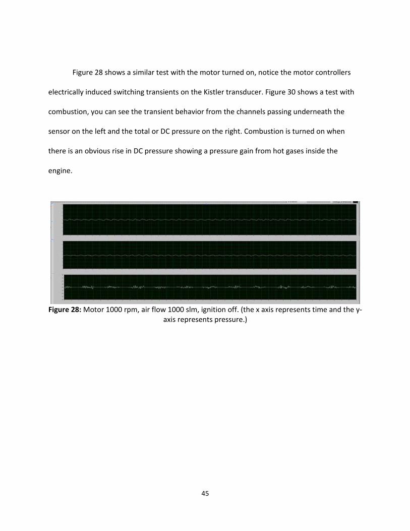
Figure 28 shows a similar test with the motor turned on, notice the motor controllers
electrically induced switching transients on the Kistler transducer. Figure 30 shows a test with
combustion, you can see the transient behavior from the channels passing underneath the
sensor on the left and the total or DC pressure on the right. Combustion is turned on when
there is an obvious rise in DC pressure showing a pressure gain from hot gases inside the
engine.
Figure 28: Motor 1000 rpm, air flow 1000 slm, ignition off. (the x axis represents time and the y-
axis represents pressure.)

46
Figure 29: Test with combustion, 900 rpm, transient pressure on left, DC pressure on right. (the
x axis represents time and the y-axis represents pressure. Leftmost is transient response, rightmost is absolute or amplitude.)
It is apparent that the sensors work as expected; they are very resistant to noise and
perform much better than the Kistler sensor. Notice the very clear switching harmonics created
by the thingap motor that the Kistler is picking up in figure 28. These are not changes in
pressure but are electromagnetic fields that are being induced onto the Kistler. This can cause
problems if the source of the induced signal is not identified and is mistakenly thought to be
actual pressure variations inside the engine.
The temperature Sensors are small footprint k or j type thermocouples with a custom
housing that fits the standard M10 threads used in all wave disk engines for instrumentation.
They are isolated from the chassis by a ceramic casing. See figure 30. The small size and
isolation insures high speed temperature profiles to be measured. See figure 31 for a
temperature profile during combustion.

47
Figure 30: Temperature sensors.
Figure 31: Temperature profile during ignition event (the x axis represents time and the y-axis
represents temperature. The different lines are separate sensors.)
3.10 VIDEO MONITORING
Due to the layout and location of the test cell and control room a direct viewing window
between the two spaces was not possible. This poses more than just an inconvenience, it is
important to be able to view the test at all times to insure proper operation and to see if
something goes wrong. To get around this problem, a four channel, 4 camera DVR system has
been installed in the test cell. The DVR can be backed up or monitored through the control
computer or the Ethernet network, consequently allowing a live view of a test anywhere in the
world, using the assigned IP address. There is also always between two and four HD USB based
48
video cameras used that allow high resolution video feedback of each test, and since they are
small and portable they can be positioned almost anywhere inside the cell.
For audio feedback and recording there is an Audio Technica USB condenser
microphone installed in the test cell. This allows high quality audio capture, which have be used
to perform FFTs to monitor combustion or ignition discrepancies. It also allows for high quality
audio feedback in the control room, making it easier for human based engine control and
testing. Simple hearing the engine rev, as any mechanic can attest to, helps to gain insight into
the operation of the wave-disk engine.
3.11 SAFETY
The system has been well designed and tested to insure safe operation. Room
environmental controls monitor gas levels and temperature and several high speed fans allow
the air in the room to be evacuated quickly. The engine controls include a keyed start box as
well as several layers of E-stop.
An on screen E-stop stops the motor but leaves all peripherals running. A manual E-stop,
forces all controls to zero to insure gas controls stop and ignition is disabled. A room E-stop
shuts off all power to the test cell in the event of a major malfunction where uncombusted
gases may be in the room or leaking. The environmental controls are built into the “major” E-
stop so the system will trip without human interaction any time certain percentages of ethane,
methane or hydrogen are detected.
49
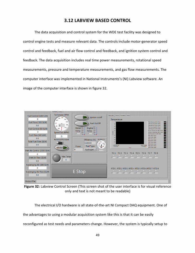
3.12 LABVIEW BASED CONTROL
The data acquisition and control system for the WDE test facility was designed to
control engine tests and measure relevant data. The controls include motor-generator speed
control and feedback, fuel and air flow control and feedback, and ignition system control and
feedback. The data acquisition includes real time power measurements, rotational speed
measurements, pressure and temperature measurements, and gas flow measurements. The
computer interface was implemented in National Instruments’s (NI) Labview software. An
image of the computer interface is shown in figure 32.
Figure 32: Labview Control Screen (This screen shot of the user interface is for visual reference
only and text is not meant to be readable)
The electrical I/O hardware is all state-of-the-art NI Compact DAQ equipment. One of
the advantages to using a modular acquisition system like this is that it can be easily
reconfigured as test needs and parameters change. However, the system is typically setup to

50
accommodate 8 pressure measurements, 16 temperature measurements, 4 mass flow
controller interfaces, 1 motor controller interface, 1 ignition control relay, 1 tachometer input
as well as all safety monitoring and feedback instruments. In addition to the Compact DAQ
system, one of the motor drives is directly controlled by Labview via Ethernet Industrial
Protocol. A block diagram of the DAQ is illustrated in figure 34.
Figure 33: DAQ block diagram
An Ipad is used for system maintenance, setup and testing. A remote log on application
allows the entire Labview interface, and consequently, the whole test cell to be run from the I-
pad. This helps greatly in debugging before a test, because each aspect of the system can be
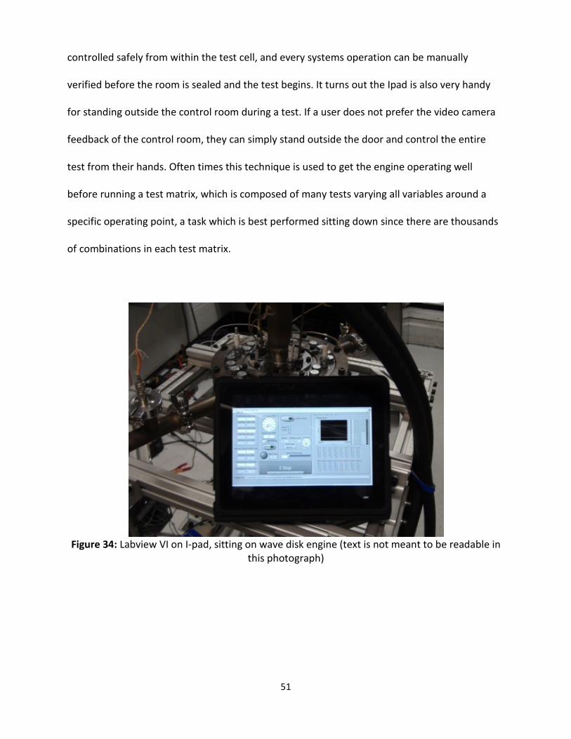
51
controlled safely from within the test cell, and every systems operation can be manually
verified before the room is sealed and the test begins. It turns out the Ipad is also very handy
for standing outside the control room during a test. If a user does not prefer the video camera
feedback of the control room, they can simply stand outside the door and control the entire
test from their hands. Often times this technique is used to get the engine operating well
before running a test matrix, which is composed of many tests varying all variables around a
specific operating point, a task which is best performed sitting down since there are thousands
of combinations in each test matrix.
Figure 34: Labview VI on I-pad, sitting on wave disk engine (text is not meant to be readable in
this photograph)

52
4 OPTICAL WAVE DISK ENGINE TEST CELL
A second Wave Disk Engine was set up in the Laser Diagnostics laboratory at MSUs EARL
(Energy and Automotive Research Laboratory). The engine was designed with quartz viewing
windows installed so high speed imaging and laser diagnostics could be performed to study the
propagation of the flame front in the curved, rotating channels of the wave disk engine. A high
speed camera was purchased for the task. An 8020 rig was constructed to provide safety from
the engine and provide a sturdy stand which to house the Wave Disk and its associated
electronics. See figure 35 for a view of the test cell.
Figure 35: Second WDE test facility with optical access.
The entire system consists of an ignition system, a motor/generator fuel and air control
and complete data acquisition system. This test cell, while using a much smaller footprint, still

53
has full control and feedback functionality. Like the larger test cell, a National Instruments
Compaq daq data acquisition unit controls and monitors fuel and airflow into the engine,
several temperatures, ignition, and motor control. The system has been very successful in
studying flame propagation patterns and has helped to tune the other wave disk engines to
have complete combustion inside the channels.

54
5 CONCLUSION
A new prototype engine design and a custom test environment was designed, built and
the prototype was tested In only 30 months. The system uses modern data acquisition
hardware and is able to control and monitor hundreds of analog and digital signals in order to
complete test sequences on an engine prototype. This feat is possible because advances in
technology allow larger data acquisition and control systems to be designed and implemented
in a shorter period than previously possible. Advanced simulation and design programs allow
fewer prototypes to be tested before a suitable real design is finished. Also todays engineers
and scientists are as captivated as ever at the idea of inventing, designing, and developing
something new. More than ever the need for more efficient, cheaper power generation
systems are needed in order to curb current fossil fuel use and pave the way for a future with
cheap limitless energy.
When compared to todays IC engines like those used in automobiles and small scale
power generation; the wave disk engine has many advantages. It is small (high power to weight
ratio) meaning that it can be cheaper and use less space than a similar power output IC engine;
it has a single moving part making it easier to build, troubleshoot and fix, and it can easily be
modified for small scale power generation as well as automobile power trains.
This small but efficient engine design promises to hold exciting potential for serial hybrid
vehicles and small scale power generation. The team at MSU has been solving each obstacle as
it is encountered. The wave disk engine pushes the state of the art in many mechanical and
electrical systems.

55
REFERENCES

56
REFERENCES
1. P. Parraga-Ramirez, M. Varney, E. Tarkleson, N. Müller , P. Akbari , J. Piechna. Development of a Wave Disk Engine Experimental Facility. 2012.
2. Mueller, Norbert, et al., et al. 7,555,891 East Lansing MI USA, 2009.
3. Development of a Wave Disk Engine Experimental Facility. P. Parraga-Ramirez, M. Varney, E. Tarkleson, N. Mueller, P. Akbari, J. Piechna. Atlanta, Georgia : AIAA/ASME/SAE/ASEE Joint Propulsion Conference and Exhibit, 2012. AIAA 2012-3703.
4. Radial-Flow Wave Rotor Concepts, Unconventional Designs and Applications. Piechna, Janusz, et al., et al. Anaheim, California : ASME, 2004. ASME International Mechanical Engineering Congress.
5. A Review of Wave Rotor Technology and Its Applications. Akbari, Pejman, Nalim, Razi and Mueller, Norbert. 2006, Journal of Engineering for Gas Turbines and Power.
6. Thermodynamics of the Wave Disk Engine. Sun, G., et al., et al. Atlanta Geogia : AIAA/ASME/SAE/ASEE Joint Propulsion Conference and Exhibit, 2012.
7. Thingap Corporation. [Online] 2012. [Cited: Aug 20, 2012.] http://www.thingap.com.
8. Eminent Technologies. [Online] 2011. [Cited: September 9, 2012.] http://www.rotarywoofer.com/.