Embed Size (px)
Citation preview
APRIL 14th, 1934
RE6, UaS.PAT. OFI?
The First and Only National Radio Weekly
629th Consecutive Issue Thirteenth Year
ULTRA -FREQUENCY 1, 5 fi
OSCILLATORS Per Copy
PICTURE DIAGRAM OF 2 -TUBE SET
FOR SHORT WAVES R
-MYI11111-.
le/IULTI-RANGE DIAL SYSTEMS
ALL -WAVE 11 -TUBE SKY -RAIDER
A Super for Broadcasts, a Doable Super for Short Waves. For Alan Mannion's Article on His Excellent Receiver, See Pages 12 and 13.
www.americanradiohistory.com
RADIO WORLD _April 14, 1934
LINE -BLOCKED UNIVERSAL TEST OSCILLATOR
THIS Test Oscillator, Model 30 -NB, is service- able for all intermediate frequencies from 135
k.c. up, and all broadcast frequencies, for lining up the receiver channels. It is constantly modula- ted and the same instrutßent works on 90-120 volts a.c. (any line frequency), line d.c. or bat- teries. A new improvement is line blocking, so the only feed to the receiver is through a wire from output post of Test Oscillator. Frequencies are direct -reading and never more than 1% off. Model 30 -NB is contained in shield cabinet. Etched metal scale is non -warping. Oscillator sent free (complete with 30 -tube, ready to operate) on receipt of $12 for a 2 -year subscription for Radio World (104 issues, one each week). Order Cat.
30 -NB.
RADIO WORLD, 145 West 45th Street, New York, N. Y.
You Can't Beat -this price-
4G.%0 COMPLETE
T isn't often that such an opportunity presents
itself. Take advantage of this low price. We cannot guarantee that we will have these pickups long because they will go fast at this low price.
for a genuine Stromberg=Carlson MagneticPickup
Outfit - ` vj?'il-Pltlt¡j'lé iE"i1tTiEitiliE :-=ï=-- +
_ ..._
.römbër: =.Clarlsöri -rt f
INPUT
TRANSFORME R
e
- rsctrnnn
A- RELIABLE RADIO Co. 145 West 45th Street, New York City
f PICKUP HERO
PICKUP PLUG
VOLUME CONTROL KNOB
The outfit is abso- lutely complete, packed neatly in compartments of original Stromberg - Carlson box.
Selected Quality Tubes FREE With Subscriptions for Radio World Here is your opportunity to subscribe
for RADIO WORLD and get just the tube or tubes you want, made by a very large, reliable, licensed tube manufac- turer; picked tubes you'll appreciate. On this offer you have five days after receipt to put the tube to any logical test, and if not entirely satisfied with its performance, return it for replacement.
For an 8 -week subscription (8 issues, one each week), at the regular price, $1.00, you may select any one of the fol- lowing tubes as free premium, or more at the same rate ($2, 16 -weeks subscrip- tion for two tubes, etc.), from this par- ticular list: OlA, 01AA, IV, 12Z3, 112A, 24A, 26, 27, 30, 31, 35, 36, 37, 38, 39, 45,
47, 51, 56, 71A, 80, 82. With a 13 -week subscription (13 is -
RADIO WORLD, 145 West
sues), at the regular price, $1.50, any one of the following tubes, or more at the same rate, from this particular list (two for a 26 -week $3.00 subscription, three for 39 -week $4.50 subscription, four for 52 -weekly, yearly $6.00 sub- scription, etc.), 1A6, 5Z3, 2A5, 2A6, 2A7, 2B7, 6A4, 6A7, 6B7, 6F7, 25Z5, 22, 32, 33, 34, 41, 42, 44, 46, 49, 53, 55, 57, 58, 59, 67, 75, 77, 78, 83, 83V, 84, (6Z4), 85, 89, 483, 485.
For a $4.00 subscription, 34 weeks (34 issues), one No. 10 tube or one No. 50 tube may be obtained.
You may select any assortment of tubes desired and send in a subscrip- tion amount for the total required un- der the above classifications.
45th Street, New York, N. Y.
SPEAKER REPAIRS Free edge cone and voice coil assembly. Field coils for all Dynamic Speakers.
We take care of all your speaker troubles. THE MOST COMPLETE ORGANIZATION OF ITS KIND IN THE UNITED STATES
Cleartone Speaker Service Fourth Floor
72 Cortlandt Street New York City
For information about the
"SKY -RAIDER" 11 -tube all -wave receiver
Write to
MANNION LABORATORIES 135 Liberty St., New York City This laboratory will gladly furnish estimates or designs on special receivers or other
electronic equipment.
UNIVERSAL Stretched -Protected
Diaphragm Type 1934 Model "BB"
Now with stretched diaphragm fuly protected against damage. Superlative Quality of reproduc- tion makes Model 'BB" the general all purpose microphone for both- voice and music. No increase in price. Sold by Job- bers everywhere. Universal Microphone Co.. Ltd..
Inglewood, Cal.. U. S. A.
HENLEY'S "TWENTIETH CENTURY BOOK OF RECIPES, FORMULAS & PROCESSES." New 1933 Edition. Ten thousand procese.., recipes, trade secrets and money -making formulas. For the laboratory, workshop, factory and home. Some subjects fully covered: Dyes, Inks, Waterproofing, Perfumes, Cement, Plating, Glass, Dentifrices, Varnishes, Soaps, Glues, Paints, Adhesives, Ea- amelling, Hairdressings, Cosmetics, Oils. Price, $4.00. Book Dept., Radio World, 145 W. 45th St., New York City.
RADIO WORLD AND RADIO NEWS. Both for one year, $7.00. Foreign, $8.50. Radio World, 145 W. 45th St.. N. Y. City.
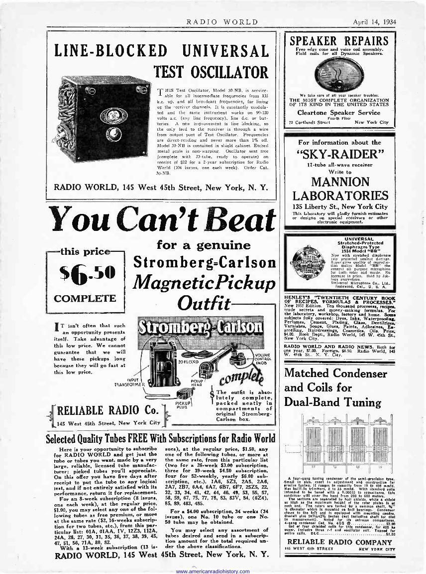
Matched Condenser and Coils for Dual -Band Tuning
1111111
1 Lai Km A four -gang tuning condenser of the seml-preelston type.
Small in size, exact In adlustment and construction for precise tuning. it ranges In capacity from 18 to 100 mmfd. Has built -In trimmers. 8 to 35 mmfd. With standard cells Intended to be tuned with a 0.00035 to capacitance. this condenser will cover the band from 200 to 000 meters.
The sections are separated by half shields. while shield as high as the maximum height of the rotor plates Is at each end. The rotors are turned by a common shaft, a/a" n diameter which is mounted on ball hearings. Condenser
closes to the left and Is soul Aped with mounting spades. Overall size 5x31/4x23/4 Inches (not Including shaft for dial in measurement). Noted for its extreme compactness. 4 -gang condenser Cat. No. 4GO # 52.95
Set of four shielded coils for this condenser, for 460 ks super, includes three r -f and oscillator coll. Tapped for police calls. D LC $1.50
RELIABLE RADIO COMPANY 145 WEST 45th STREET NEW YORK CITY
www.americanradiohistory.com
April 14, 1934 RADIO WORLD 3
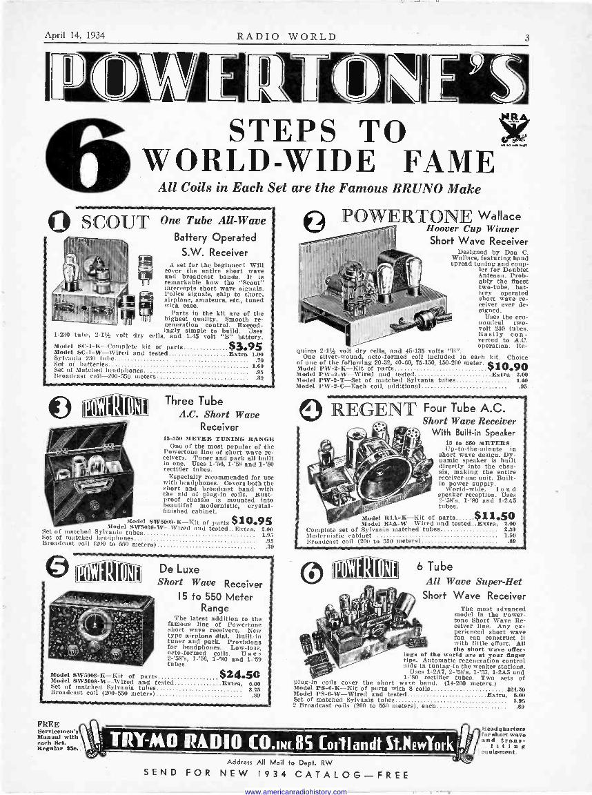
i ITIVI ttlIZI 6 STEPS TO WORLD-WIDE FAME
All Coils in Each Set are the Famous BRUNO Make
O scot
1-230 tube, 2-1% volt dry
T One Tube All -Wave Battery Operated
S.W. Receiver A set for the beginner! Will
cover the entire short wave and broadcast bands. It is remarkable how the "Scout" Intercepts short wave signals. Police signals, ship to shore, airplane, amateurs, etc., tuned with ease.
Parts in the kit are of the highest quality. Smooth re- generation control. Exceed- ingly simple to build. Uses
cells, and 1-45 volt "B" battery. Model SC-1-K-Complete kit of parts Model SC-1-W-Wired and tested Extra 1.00 Sylvania 230 tube .40 Set of batteries 1.80 Set of Matched headphones ,98 Broadcast coil -200-550 meters .39
$3.95
ff..) 111\1111[11N Three Tube
I K11 l J A.C. Short Wave Receiver
15-550 METER TUNING RANGE One of the most popular of the
Powertone line of short wave re- ceivers. Tuner and pack all built in one. Uses 1-'56, 1-'68 and 1-'80 rectifier tubes.
Especially recommended for nee with headphones. Covers both the short and broadcast band with the aid of plug-in coils. Rust- proof chassis is mounted into beautiful modernistic, crystal - finished cabinet.
Q .Model SW5009-K--Kit of parts $10.95 Model SW5009-W-Wired and tested.. Extra, 2.00 Set of matched Sylvania tubes 1.95 Set of matched headphones .95 Broadcast coil (200 to 550 meters) .39
® . I I , C lI I De Luxe
Short Wave Receiver 15 to 550 Meter
Range The latest addition to the
famous line of Powertone short wave receivers. New type airplane dial. Built-in tuner and pack. Provisions for headphones. Low -loss, octo-formed coils. Uses 2-'58's, 1-'58, 1-'80 and 1-"59 tubes.
Model SW5008-K-Kit of parts $24.50 Model - - Extra. 5.00 3.75
.89 Set of matched Sylvania tubes - Broadcast coil (200-550 meters) i
FREE Servicemen'. Manual with each Set. Regular 25e.
quires 2-1% volt dry cells, and 45-135 volts "B". One silver -wound, octo-formed coil included in each kit. Choice
of one of the following 20-32, 40-60, 75-150, 150-200 meter. Model PW-2-K-Kit of parts $10.90 Model PW-2-W-Wired and tested Extra 2.00 Model PW-2-T-Set of matched Sylvania tubes 1.40 Model PW-2-C-Each coil, additional .95
POW'PATON J; Wallace Hoover Cup Winner Short Wave Receiver
Designed by Don C. Wallace, featuring band spread tuning and coup-
ler for Doublet Antenna. Prob- ably the finest two -tube, bat- tery operated short wave re- ceiver ever de- signed.
Uses the eco- nomical two - volt 230 tubes. Easily con- verted to A.C. operation. Re-
R Four Tube A.C. Short Wave Receiver'
With Built-in Speaker 15 to 550 METERS Up-to-the-minute in
short wave design. Dy- namic speaker is built directly into the chas- sis, making the entire receiver one unit. Built- in power supply.
World-wide, loud speaker reception. Uses 2-'58's, 1-'80 and 1-2A5 tubes.
$11.50 Model R4A-W-Wired and tested ..Extra, 2.00
Complete set of Sylvania matched tubes 2.50 Modernistic cabinet 1.50 Broadcast coil (200 to 550 meters) .89
Model R4A-K-Kit of parts
6 Tube All Wave Super -Het
Short Wave Receiver The most advanced
model in the Power - tone Short Wave Re- ceiver line. Any ex- perienced short wave fan can construct it with little effort. All the short wave offer-
ings of the world are at your finger tips. Automatic regeneration control aids in tuning -in the weaker stations.
Uses 1-2A7, 2-'58's, 1-'55, 1-2A5 and 1-'80 rectifier tubes. Two sets of plug-in coils cover the short wave band. (14-200 meters.)
Model PS-6-K-Kit of parts with 8 coils $24.50 Model PS-6-W-Wired and tested Extra, 5.00 Set of matched Sylvania tubes 3.95 2 Broadcast coils (200 to 550 meters), each .89
ç= TRY-MO RADIO RI,DI0 CO.Dac.85 [oillandt StNewl'ork-ji :I Address All Mail to Dept. RW
SEND FOR NEW 1 9 3 4 CATALOG-FREE
Headquarters for short wave and trans- mitting equipment.
www.americanradiohistory.com

[SHORT-WAVE TOPICS ON PAGES 4, 5, 6, 7, 8, 9, 10, 11, 12 and 13.]
OFFICERS: Roland Burke Hennessy, President and Treasurer.
M. B. Hennessy, Vice. President.
Herman Bernard, Secre- tary.
ROLAND BURKE HENNESSY Editor
HERMAN BERNARD Managing Editor
REG. U. S.PAT.OF F.
n L D The First and Only National Radio Weekly
THIRTEENTH YEAR
J. E. ANDERSON Technical Editor
J. MURRAY BARRON Advertising Manager
Vol. XXV APRIL 14th, 1934 No. 5. Whole No. 629
Published Weekly by Hennessy Radio Publications Corporation, 145 West 45th Street, New York, N. Y.
Editorial and Executive Offices : 145 West 45th Street, New York Telephone: BR-yant 9.0558
Entered as second-class matter March, 1922, at the Post Office at New York, N. Y., under Act of March 3, 1879. Title registered in U. S. Patent Office. Printed in the United States of America. We do not assume any responsibility for unsolicited manuscripts, photographs, drawings, etc., although we are careful with them.
Price 15c per Copy; $6.00 per Year by mail. $1.00 extra per year in foreign countries. Subscribers' change of ad- dress becomes effective two weeks after receipt of notice.
Ultra -Frequency Oscillators Offer a Limitless Chance for Profitable
Experimenting By J. E. Anderson
C,
FIG. 1
The equivalent network of an ultraudion oscillator showing the three tube capacities, Cp, Cg, and Cm, the grid condenser C, and the inductance L. This applies to ultra-
high frequencies.
J
#5 FIG. 2
The circuit of a short-wave oscil- lator often used. It is doubly peri- odic but is converted to a Colpitts by putting a radio -frequency choke
in the B supply lead.
THE radio experimenter who has ceased to find much excite- ment in the reception of broadcast and short-wave stations but who still wishes to indulge in his hobby can get an end-
less amount of interest and pleasure out of the ultra -short waves, which he himself can generate and receive.
The advantage of working with ultra -short waves is that the apparatus costs practically nothing and no antennas of large di- mensions are required. The generation and reception of ultra -short waves is a game which any one can play, and the main prize is the generation of the shortest wave. There is comparatively little trouble in getting down to 3 meters, but to get down below one meter is a harder nut to crack. Yet anybody who has a few radio apparatuses has as good chance as any one else getting down. The utilization of the ultra -short waves after they have been generated and detected is another problem, but that, too, is in the same game.
Short -Wave Circuits The problem of generating ultra -short waves is mainly one of
reducing the distributed capacities, mainly those pertaining to the tube. Of course, the inductance can also be reduced, and must be if the generated waves are to be very short, but if the inductance is made too low, the circuit will not oscillate because it does not have enough fly -wheel effect. In an effort to reach the ultra -short
C,
FIG. 3 The equivalent network of the cir- cuit in Fig. 2 before the choke has been put in. Cl is the grid stopping condenser, which may be used for tuning if condensers C are omitted.
waves many experimenters have resorted to push-pull circuits, but little is gained in that direction, for as more tubes are added, ca- pacities are also added.
As an aid in understanding what capacities enter into the problem and in what way they affect the frequency generated, let us look at Fig. 1. This represents the a -c portion of an oscillating circuit of the ultra-audion type. There is supposed to be a radio -frequency choke in the grid circuit and another in the plate circuit, but the reactances of these are assumed to be so large that they do not affect the operation of the oscillator, that is, in respect to fre- quency. Cp is the plate to cathode capacity, Cg the grid to cathode capacity, Cm the plate to grid capacity, C the grid condenser, and L the inductor. The internal resistances are represented by rg and rp.
Now in most practical cases the internal resistances are so high their effects on the frequency can be neglected. Therefore the oscillating circuit is the network remaining when these resistances are removed, and the frequency of oscillation can be computed in terms of the capacities and the inductance. First of all, Cp and Cg are in series. Therefore their capacity is CpCg/(Cp+Cg). For short, let us call this K. Across this capacity is the grid to plate capacity Cm. Therefore we have K+Cm. This in turn is in series with C, and therefore the total effect capacity in the
www.americanradiohistory.com
April 14, 1934 RADIO WORLD 5
Ch
Ch
+B A -A
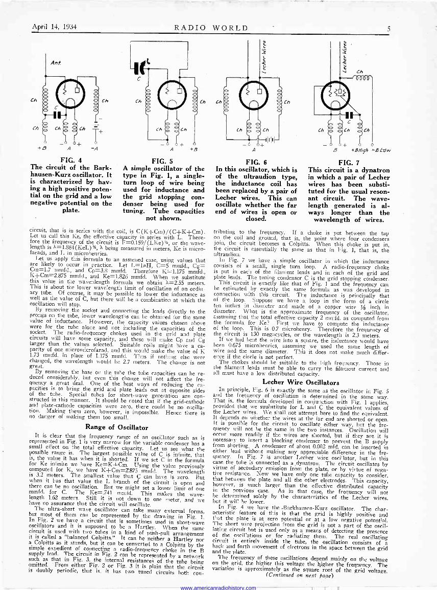
FIG. 4 The circuit of the Bark - hausen -Kurz oscillator. It is characterized by hav- ing a high positive poten- tial on the grid and a low negative potential on the
plate.
Ch
Ch
A +B
FIG. 5 A simple oscillator of the type in Fig. 1, a single - turn loop of wire being used for inductance and the grid stopping con- denser being used for tuning. Tube capacities
not shown.
Ch
circuit, that is in series with the coil, is C (K+Cm) / (C-FK+Cm). Let us call this Ke, the effective capacity in series with L. There- fore the frequency of the circuit is F=0.159/(LKe)%, or the wave- length is X=1.884 (KeL) %, X being measured in meters, Ke is micro - farads, and L in microhenries.
Let us apply this formula to an assumed case, using values that are likely to occur in practice. Let L=14H, C=5 mmfd., Cg= Cm=1.7 mmfd., and Cp=3.8 mmfd. Therefore K=1.175 mmfd., K+Cm=2.875 mmfd., and Ke=1.826 mmfd. When we substitute this value in the wavenlength formula we obtain X=2.55 meters. This is about the lower wavelength limit of oscillation of an ordin- ary tube. Of course, it may be possible to lower the inductance as well as the value of C, but there will be a combination at which the oscillation will stop.
By removing the socket and connecting the leads directly to the prongs on the tube, lower wavelengths can be obtained for the same value of inductance. However, the capacity values chosen above were for the tube alone and not including the capacities of the socket. The radio -frequency chokes used in the grid and plate circuits will have some capacity, and these will make Cp and Cg larger than the values selected. Suitable coils might have a ca- pacity of one micromicrofarad, and this would make the value of K 1.73 mmfd. in place of 1.175 mmfd. Thus if nothing else were changed, the wavelength would be 2.7 meters. The change is not great.
By removing the base on the tube the tube capacities can be re- duced considerably, but even this change will not affect the fre- quency a great deal. One of the best ways of reducing the ca- pacities is to bring the grid and plate leads out at opposite sides of the tube. Special tubes for short-wave generation are con- structed in this manner. It should be noted that if the grid -cathode and plate -cathode capacities were zero, there could be no oscilla- tion. Making them zero, however, is impossible. Hence there is no danger of making them too small.
Range of Oscillator It is clear that the frequency range of an oscillator such as is represented in Fig. 1 is very narrow for the variable condenser has a small effect on the total effective capacity. Let us see what the possible range is. The largest possible value of C is infinite, that is, the value it has when it is shorted. If we set C in the formula for Ke infinite we have Ke=K+Cm. Using the value previously computed for K, we have K--Cm=2.875 mmfd. The wavelength is 3.2 meters. The smallest value that C can have is zero. But when it has that value the L branch of the circuit is open and there can be no oscillation. But we might set a lower limit of one mmfd. for C. The Ke=.741 mmfd. This makes the wave- length 1.62 meters. Still it is not down to one meter, and we have no assurance that the circuit will oscillate. The ultra -short wave oscillator can take many external forms, but most of them can be represented by the drawing in Fig. 1. In Fig. 2 we have a circuit that is sometimes used in short-wave oscillators and it is supposed to be a Hartley. When the same circuit is used with two tubes in a kind of push-pull arrangement
it is called a "balanced Colpitts." It can be neither a Hartley nor a Colpitts as it stands, but it can be converted to a Colpitts by the simple expedient of connecting a radio -frequency choke in the B supply lead. The circuit in Fig. 2 can be represented by a network such as that in Fig. 3, the internal resistances of the tube being omitted. From either Fig. 2 or Fig. 3 it is plain that the circuit is doubly periodic, that is, it has two tuned circuits both con -
Ch Ch
FIG. 6 In this oscillator, which is of the ultraudion type, the inductance coil has been replaced by a pair of Lecher wires. This can oscillate whether the far end of wires is open or
closed.
B +BHigh *B Lew
FIG. 7 This circuit is a dynatron in which a pair of Lecher wires has been substi- tuted for the usual reson- ant circuit. The wave- length generated is al- ways longer than the
wavelength of wires.
tributing to the frequency. If a choke is put between the tap on the coil and ground, that is, the point where four condensers join, the circuit becomes a Colpitts. When this choke is put in, the circuit is essentially the same as that in Fig. 1, that is, the ultraudion.
In Fig. 7 we have a simple oscillator in which the inductance consists of a small, single turn loop. A radio -frequency choke is put in each of the filament leads and in each of the grid and plate leads. The tuning condenser C is the grid stopping condenser. This circuit is exactly like that of Fig. 1 and the frequency can
be estimated by exactly the same formula as was developed in connection with this circuit. The inductance is principally that of the loop. Suppose we have a loop in the form of a circle ten inches in diameter and made of a copper wire % inch in diameter. What is the approximate frequency of the oscillator, assuming that the total effective capacity 2 mmfd. as computed from the formula for Ke? First we have to compute the inductance of the loop. This is 0.7 microhenry. Therefore the frequency of the circuit is 130 megacycles, or the wavelength is 2.3 meters.
If we had bent the wire into a square, the inductance would have been 0.675 microhenries, assuming we used the same length of wire and the same diameter. This it does not make much differ- ence if the circle is not perfect.
The chokes should be suitable to the high frequency. Those in the filament leads must be able to carry the filament current and all must have a low distributed capacity.
Lecher Wire Oscillators In principle, Fig. 6 is exactly the same as the oscillator in Fig. 5
and the frequency of oscillation is determined in the same way. That is, the formula developed in conjunction with Fig. 1 applies, provided that we suubstitute for L and C the equivalent values of the Lecher wires. We shall not attempt here to find the equivalent. It depends on whether the wires at the far end are shorted or open. It is possible for the circuit to oscillate either way, but the fre- quency will not be the same in the two instances. Oscillation will occur more readily if the wires are shorted, but if they are it is necessary to insert a blocking condenser to prevent the B supply from shorting. A condenser of about 0.002 mfd. can be inserted in either lead without making any appreciable difference in the fre- quency. In Fig. 7 is another Lecher wire oscillator, but in this case the tube is connected as a dynatron. The circuit oscillates by virtue of secondary emission from the plate, or by virtue of nega- tive resistance. Now we have only one tube capacity to consider, that between the plate and all the other electrodes. This capacity, however, is much larger than the effective distributed capacity in the previous case. As in that case, the frequency will not be determined solely by the characteristics of the Lecher wires, but it will be lower.
In Fig. 4 we have the -Barkhausen-Kurz oscillator. The char- acteristic feature of this is that the grid is highly positive and that the plate is at zero potential or at a low negative potential. The short wire projection from the grid is not a part of the oscil- lating circuit but is used only as a means of detecting the presence of the oscillations or for radiating them. The real oscillating circuit is entirely inside the tube, the oscillation consists of a back and forth movement of electrons in the space between the grid and the plate.
The frequency of these oscillations depend mainly on the voltage on the grid, the higher this voltage the higher the frequency. The variation is approximately as the square root of the grid voltage.
(Continued on next Page)
www.americanradiohistory.com
6 RADIO WORLD April 14, 1934
Segregating the Duo -Diode of the 55 for Independent Second
Detection and A. V. C. By Roger Braddock
i JB
aarnn
-.000, ,IlAr- - 001» lli.rti
.1000,
1.274 r C
C aaTnll.
Ma
C c
0
36 2Ad
MAL
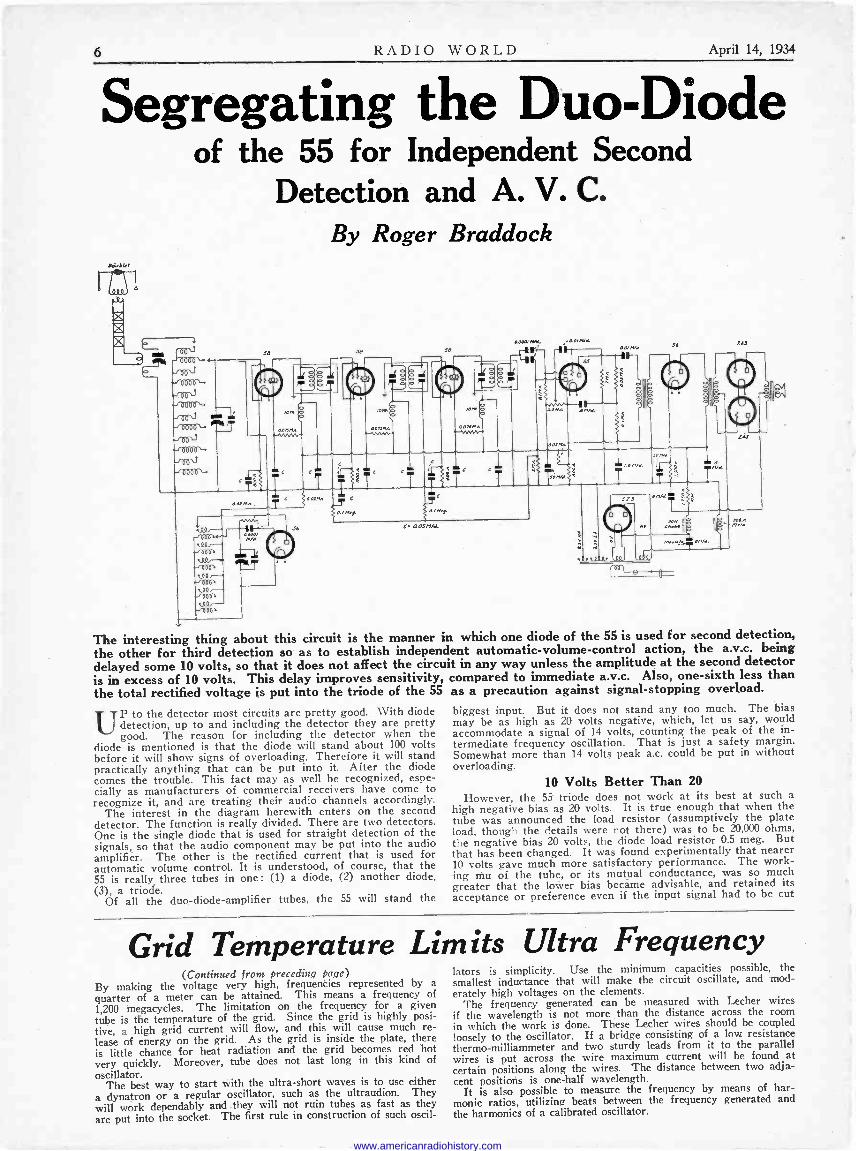
The interesting thing about this circuit is the manner in which one diode of the 55 is used for second detection, the other for third detection so as to establish independent automatic -volume -control action, the a.v.c. being delayed some 10 volts, so that it does not affect the circuit in any way unless the amplitude at the second detector is in excess of 10 volts. This delay improves sensitivity, compared to immediate a.v.c. Also, one -sixth less than the total rectified voltage is put into the triode of the 55 as a precaution against signal -stopping overload.
UP to the detector most circuits are pretty good. With diode detection, up to and including the detector they are pretty good. The reason for including the detector when the
diode is mentioned is that the diode will stand about 100 volts before it will show signs of overloading. Therefore it will stand practically anything that can be put into it. After the diode comes the trouble. This fact may as well be recognized, espe- cially as manufacturers of commercial receivers have come to recognize it, and are treating their audio channels accordingly.
The interest in the diagram herewith enters on the second detector. The function is really divided. There are two detectors. One is the single diode that is used for straight detection of the signals, so that the audio component may be put into the audio amplifier. The other is the rectified current that is used for automatic volume control. It is understood, of course, that the 55 is really three tubes in one: (1) a diode, (2) another diode, (3), a triode.
Of all the duo -diode -amplifier tubes, the 55 will stand the
biggest input. But it does not stand any too much. The bias may be as high as 20 volts negative, which, let us say, would accommodate a signal of 14 volts, counting the peak of the in- termediate frequency oscillation. That is just a safety margin. Somewhat more than 14 volts peak a.c. could be put in without overloading.
10 Volts Better Than 20 However, the 55 triode does not work at its best at such a
high negative bias as 20 volts. It is true enough that when the tube was announced the load resistor (assumptively the plate load, though the details were not there) was to be 20,000 ohms, the negative bias 20 volts, the diode load resistor 0.5 meg. But that has been changed. It was found experimentally that nearer 10 volts gave much more satisfactory performance. The work- ing mu of the tube, or its mutual conductance, was so much greater that the lower bias became advisable, and retained its acceptance or preference even if the input signal had to be cut
Grid Temperature Limits Ultra Frequency (Continued from preceding page)
By making the voltage very high, frequencies represented by a
quarter of a meter can be attained. This means a frequency of
1,200 megacycles. The limitation on the frequency for a given tube is the temperature of the grid. Since the grid is highly posi- tive, a high grid current will flow, and this will cause much re- lease of energy on the grid. As the grid is inside the plate, there is little chance for heat radiation and the grid becomes red hot very quickly. Moreover, tube does not last long in this kind of
oscillator. The best way to start with the ultra -short waves is to use either
a dynatron or a regular oscillator, such as the ultraudion. They will work dependably and they will not ruin tubes as fast as they
are put into the socket. The first rule in construction of such oscil-
lators is simplicity. Use the minimum capacities possible, the smallest inductance that will make the circuit oscillate, and mod- erately high voltages on the elements.
The frequency generated can be measured with Lecher wires if the wavelength is not more than the distance across the room in which the work is done. These Lecher wires should be coupled loosely to the oscillator. If a bridge consisting of a low resistance thermo-milliammeter and two sturdy leads from it to the parallel wires is put across the wire maximum current will be found at certain positions along the wires. The distance between two adja- cent positions is one-half wavelength.
It is also possible to measure the frequency by means of har- monic ratios, utilizing beats between the frequency generated and the harmonics of a calibrated oscillator.
www.americanradiohistory.com
April 14, 1934 RADIO WORLD 7
down to avoid overloading the triode, for it was found that more could be taken out, due to the higher gain, when the lower bias prevailed and signal was reduced accordingly, than when the higher bias existed, and the signal was permitted to enter the audio channel at maximum.
Also, the plate load resistor is now recommended to be much higher, the total resistance being in excess of 100,000 ohms, almost invariably. In the circuit herewith the effective plate load resistor is 50,000 ohms, but there is an additional resistor of 100,000 ohms, from which the signal is removed by a large capacity (8 mfd.), and besides this combination of 0.1 meg. and 8 mfd. constitutes an important hum filter. One of the worst places for hum trouble is at the detector, and this filter prevents the hum from backing into the detector through the plate circuit that is otherwise open to the reception of hum with a vengeance.
One -Sixth of Amplitude Omitted Let us examine the input to the two diodes. The usual in-
termediate -frequency transformer is present, and its secondary will be considered. From the upper or high side, looking into the 55 duo -diode, there are two condensers. The capacities are the same, 0.0001 mfd. One condenser, the upper one, connects directly to the upper diode plate, and then there is a resistor of 0.1 meg. that continues from that point in the direction of the cathode. However, a resistor of 0.5 meg. goes to the cathode, and therefore the total resistance, looking from the condenser just mentioned, to the cathode, is 600,000 ohms, or 0.6 meg. This total expresses the load used for the detector itself, the so-called second detector or demodulator, and the tube depended on for the audio frequencies to feed the follow- ing channel.
But we must realize that the rectification affects the total 600,000 ohms, and since a slider moves across the 500,000 ohms (0.5 meg.) to grid of the triode in the 55, reached through a condenser, it is obvious that not all of the rectified voltage is delivered to the triode. In fact, the total voltage is represented by 600,000 ohms, and that taken off is represented by 500,000 ohms at "full -on" position of the manual volume control, there- fore one -sixth of the rectified voltage is not utilized at all. The reason is plain enough. If that other sixth were added to the in- put to the audio amplifier there would be premature overload of the audio channel. Besides there might be some inter- mediate -frequency oscillation, because the amplitude at the detector affects the oscillatory tendency of the intermediate channel, always dangerously high unless special safeguards are taken.
Delay Voltage From the pointer through a condenser to the grid, with grid
return through 2 meg. to ground, represents the input, while the output is effectively that developed across the 50,000 ohms, being fed to the primary of the interstage audio transformer.
Thus have we accounted for the second detector. Perhaps as good a name as any for the purpose to which the
other diode is put is third detector, though the service rendered is automatic volume control. What is the advantage of this severance? Are not the functions usually combined? Why not stick to the simpler method of using the same detection for second and third detection, that is, for demodulation and also for automatic volume control?
Answer: If the functions are separated it is possible to in- troduce a delay voltage quite easily, of such a type that the automatic volume control will not start functioning prematurely, but will be ineffective until the signal itself has risen to a certain amplitude, when the service that a.v.c. offers is most important. In other words, while it is true that the considera- tions just put forward, that too much could be delivered to the triode, whereby that tube would overload, do prevail, a.v.c. may be introduced to check that tendency, but when a.v.c. is the rule, and is untamed, the danger is there will be too much of it.
While a.v.c. is never effective unless and until there is a signal of some ratable amplitude, yet it may become effective at a signal amplitude too low for the intentions. In other words, the drain on sensitivity may be too great.
It is a fact that one of the attributes of a.v.c. is that it tends to correct for fading, but in practice this benefit is not as great as some imagine, and therefore steps are taken not to permit a.v.c. to constitute too much of a drain on the sensitivity of the receiver to serve a largely theoretical no -fading purpose. That means of checking a.v.c. is developed through delay voltage, or time lag, or holding back the a.c.v. action until the amplitude for detection proper is of a sufficiently high level. All these views or aspects of the situation paint the same picture. A.v.c. is made to trail after detection, and is not introduced until con- siderable detecting amplitude is reached.
How the Bias Arises Suppose, then, that the negative bias on the triode of the
55 is made 10 volts. Then there is no danger of overloading the 55 until the signal exceeds 7 volts (an assumption that again is over -cautious). At this point, however, the a.v.c. is made to function, and when the signal itself tends to raise its head above 7 volts, a.v.c. comes along and bows that head as if with a yoke on the neck, reducing the i -f amplification until no more than 7 volts ever get into the triode. Therefore the circuit
is protected at the triode of the 55, the most vulnerable point, and though overload may occur subsequently, still it is not of the signal -stopping tyne, and besides one always has the manual volume control at his command in the event the signal is heard too loudly and too roughly for comfort.
It has been stated that the 55 triode is negatively biased. This is true because there are a resistor of 800 ohms between cathode and ground, and another resistor from B plus to cathode (50,000 ohms) that sends B current through the biasing resistor independent of the plate current of the tube, and thus the 10 volts are developed, the grid being returned to grounded B minus. Moreover, the bias does not depend entirely on the plate current of the 55 triode but strongly on the bleeder, which thus acts as a stabilizing agent, since the bias is steadied. Bias dependent on signal alone is unsteady.
Input to Third Detector We have discussed the input to one triode, the true detector,
but not the input to the other diode, the a.v.c. section or unit. We found that the resistance network between the 0.0001 mfd. stopping condenser and the detector wound up at cathode for the demodulator or straight detector. Therefore whatever recti- fied voltage was developed was put into the triode, except one - sixth of the total which never could get into the audio amplifier.
With the a -v -c section it is quite different. Assuming a negative bias of 10 volts, measured between cathode and ground, we know from our familiarity with rectifiers that there is no possibility of rectification unless the anode goes positive. It is made positive by the signal. If the return is to a negative point, in respect to cathode, must not the signal overcome this bias before there is any rectification? Of course. Therefore we have lifted the a -v -c tube 10 volts above ground or B minus potential, and required that the signal itself be more than 10 volts before a.v.c. is introduced at all. We find that out by examining the 2.0-meg. load resistor of the a -v -c diode. It is returned to B minus, which is 10 volts negative in respect to cathode. The second detector resistor network was returned to cathode for immediate effect of detection, but the a -v -c- load resistor is returned to ground, for a delayed voltage equal to the bias.
The method is similar to that used in Atwater -Kent receivers. It is more or less standard with this manufacturer, although the A -K circuit is quite different from the one illustrated. The prin- ciple of delay is there; however.
Antenna and Coupling It is only in respect to the 55 tube that the commercial receiver
is somewhat similar, but by no means identical. The rest of the circuit differs entirely from the commercial model just men- tioned.
The circuit herewith portrays an all -wave receiver, using a built-in matching transformer of the step-up type, with primary rotatable for alteration of coupling, and with a condenser in series with the split secondary. Ahead of this primary is a transposition line of the standard type, leading to the stepped - down secondary of a transformer that is situated at or near the doublet antenna. The doublet may consist of a total of 40 feet or so of wire as high as possible, supported by masts, with an insulator at center separating the two severed stretches. The theory and practice of the installation of such a transmission line, with step-down transformer theory and purposes at the antenna and step-up transformer purposes at the feed to set were explained in detail in last week's issue, dated April 7th.
If the coupling is loose, as it will or should be, then one may escape with merely one tuning stage associated with the pre - selector tube proper, for the tuning of the input transformer is the equivalent of another tuned circuit, at short waves at least, hence the coil problem is solved more easily.
The Output Stage The coupling between 56 oscillator and 58 modulator is made
by a condenser effect resulting from a piece of insulated wire held close to one grid wire by spaghetti and close to the other grid wire by the same means.
The intermediate channel is standard, and the values will be found on the diagram.
Passing to the driver, we find the 56 feeding 2A3 push-pull tubes. Care should be taken to adjust the biases independently on the 2A3's, if need be, to adjust the plate voltage through series resistance, until the plate current through one tube is exactly the same as that through the other, to avoid hum.
Something of a novelty is the inclusion of the speaker field, only 300 ohms, in the negative leg of the rectifier, and con- nection of the power tubes' return so that the potential differ- ence across this field supplies the negative bias of around 55 volts or so, while the main filter choke is an independent unit, marked 30 henries, the d -c resistance of which is not very material, except that in the interest of good regulation of the B system, the d -c- resistance of this choke should not be more than 1,000 ohms.
A circuit of this type will be found to yield excellent results, and may be adopted, from first intermediate on, for almost any a -c receiver. The coil problems for all -wave coverage, and how to obtain a satisfactory switch, are other considerations. They are important, but they are beyond the scope of the present article, which deals mainly with splitting up the diode uses of the 55 and establishing a safeguarded input to the audio amplifier.
www.americanradiohistory.com

8 RADIO WORLD April 14, 1934
SHORT-WAVE OSCILLATORS Single -Pole Switching for Five Bands
Station Finder By Leonard Hopkins
O a O
d pO a o o b ma1 3 ó O 9 á e 7rr11 1
B-
0.OSP1.a.
rÌ
To Modalalor
0.02MA
r
O.lMfd.
For use in a receiver having switch -operated coil systems, the oscillator switching may be reduced to a
single pole by using the method outlined.
THE Hartley oscillator is a popular one for short waves. If this type of oscillator is used with a heater tube, such as the 56, then it is possible to switch to various bands by using a
single -pole switch. The number of throws or positions of the switch of course will depend on the number of bands to be covered, in this instance five. The upper diagrams show how this is done.
The lowest -frequency coil has a tap about one -quarter the total number of turns from the return end, and this tap is connected to cathode. If successive coils are paralleled with the low -frequency inductance, one at a time, the frequencies generated will be higher, and the inductances are selected on the basis of Ohm's law, or may be done experimentally.
The formula for the parallel inductances is the same as that for parallel resistors, assuming there is no mutual inductive coupling between the two coils. This formula, in words, is that the resultant hr
v ` O.05MJt
1/4 ..._J 1 34
O.OSMJL
SW.
V. 22.5V.
II{ 111111I1-- + - +
/. 0 Mfd.
SO Mmfd.
A test oscillator, using plug-in coils, may be con- structed from this pattern. The A battery voltage is 3 volts, and the designation "2 volts" should be read
as applying to the filament of the 34 tube.
1 d i0 , O i0
á r r rz i
O.OSMA.
56
O./ Mid.
B
0.01 M..1
0.02MA
For test oscillator service the same single -pole switch- ing arrangement may be used by following this dia-
gram. The oscillator is not modulated.
is the reciprocal of the sum of the reciprocals. Let the low -frequency coil be L and let the coil next to it in either diagram above be Ll, then the resultant inductance Lx is
1
1 1
L1 L To ascertain the necessary parallel inductance for reduction to
cover the next highest frequency band, with a bit of overlap, we obtain the frequency ratio for the low -frequency band. Say it is 2.1. We square that and get 4.61. The required inductance for no over- lap is 1/4.61 of the low -frequency inductance, which must be known. The usual commercial plug-in coil for the low -frequency band (200 to 85 meters) (0.00014 mfd. tuning) has an inductance of 70 mi- crohenries, approximately. Therefore the required inductance for the next band would be 70/4.61. To attain overlap we reduce the denominator to 4.6 and get the required inductance as 15.2 micro - henries, approximately. Therefore we must ascertain what induc- tance must be paralleled with 70 microhenries to yield a resultant of 15.2 microhenries. The simplified formula for this is :
LXLl Lx -
L-Ll where Lx is the unknown parallel inductance, L is the known in- ductance of 70 microhenries and Ll is the known inductance of 15.2 microhenries. Hence Lx = 17.6 microhenries.
Output Measurement The same procedure is applied to the next band, 70 microhenries
retained, the required net resultant inductance being 15.2/4.6, or 3.3 microhenries, the value of Lx being 3.6 microhenries.
The oscillator at upper left is intended for service in a receiver, and the method of coupling is to run a wire from close to the grid wire of the oscillator to close to the grid wire of the modulator A piece of spaghetti into which the two wires at each grid are in- serted, without touching metallically, will do nicely for holding.
The oscillator at upper right is for testing. It is not modulated. However, an output meter may be used on the device being tested, say, a receiver, and the deflection will show up all right. Modula- tion is necessary mainly for audibility, but a meter dispenses with any requirement of audibility for lining up.
Bands Covered The diagram below is for a test oscillator, also unmodulated, using
plug-in coils. It may be used as a station finder by loose coupling to areial, as may the diagram at upper right. The 2 -volt designa- tion near the A battery should be read as applying to the filament, that is, between the upper end of the 16.7 -ohm resistor and the filament point where the switch makes contact. The battery voltage is 3 volts, not 2 volts. The difference of one volt is dropped in the filament limiting resistor.
Standard plug-in coils, with a condenser of the proper capacity (usually 0.00014 mfd.) will cover the necessary bands, and no con- struction or calculation of coils is necessary.
www.americanradiohistory.com
April 14, 1934 RADIO WORLD 9
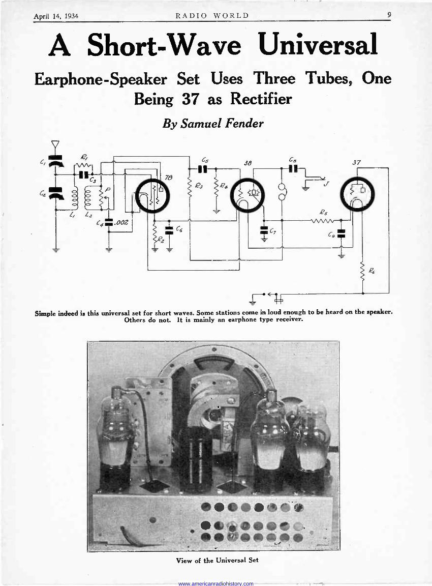
A Short -Wave Universal Earphone -Speaker Set Uses Three Tubes, One
Being 37 as Rectifier By Samuel Fender
Simple indeed is this universal set for short waves. Some stations come in loud enough to be heard on the speaker. Others do not. It is mainly an earphone type receiver.
View of the Universal Set
www.americanradiohistory.com

10 RADIO WORLD April 14, 1934
,
A Breadboard Set For Short Waves, Using Two Tubes
By Edwin Stannard Supertone Products Corporation
ANT. A- B-GND.
) + +45 +90Y YP
PHOÑES
A- F
F- G
®
® ® F+ P
o
o
,
20-d0o MMFD
COI L
SOCKET -e P F.+
© '®
- G ®
i 300T
/ .' , --
<' e
REVERSE IF REGENERATION FAILS
o
To 5W.
.000i4 M FD. I ff/,
1
.00025 MFD
e-\ SWITCH 1m
THE breadboard type of layout is popular with short-wave beginners, as they have a freedom of choice in placement of parts, allowing leeway in case of some miscalculation. The
plan presented herewith is for the construction of the conventional two -tube short-wave set, 200 to 15 meters, using plug-in coils, one coil for each band, and only a two -winding coil at that. The plan is about two-thirds scale.
This type of receiver or circuit is popular because it does bring results, at small outlay, and also provides facilities for such ex-
perimenting as the builder may desire to do, after he has got the set working.
Reversing One Winding There is only one possible difficulty, and that is that the coils
have not reverse -wound primaries or ticklers, but whichever way the coils are wound, they will provide oscillation only when connected properly, so make the reversal as indicated in the drawing, in case oscillation fails.
It has been deemed worth while to use separate filament resistors, 16.7 ohms, rather than to put two tubes on one resistor, because then if one tube filament burns out the other burns out due to the excessive voltage. While the two resistors are shown as appearing differently, in fact both will be of the wire -wound type, as one of them is depicted, and their purpose is to drop the 3 volts of the A battery to 2 volts for the filaments.
Use No. 6 Dry Cells The A cells should consist of two No. 6 dry cells series -connected,
central positive of one to edge negative of the other, the remaining or free positive of one and negative of the other for feed to the circuit as drawn.
The ratio of the audio transformer is not vastly important, but somewhat greater volume will result if the ratio is 5 to 1 rather than lower ratio, and of course the sensitivity of the earphones should be as high as you can afford.
The circuit consists of a regenerative detector and a stage of transformer -coupled audio -frequency amplification. Both fubes are of the 30 type.
The central socket is the coil receptacle.
www.americanradiohistory.com

April 14, 1934 RADIO WORLD 11
DIALLING FOR ALL WAVES By Frequency -Calibrated Methods
By Herman Bernard
Disc dial with traveling light, circular movement,
translucent scale.
Cam mechanism to move the pointer over a wide arc, instead of in a circle.
THE illustrations show four types of dials, and the question is as to their application to frequency -calibrated short-wave or all -wave receivers.
The first type, at left, is the disc dial of the traveling light type. Obviously there is not enough room on the illustrated model for the imprinting of four or more tiers representing the scales for as many bands of tuning. However, if the size of the scale as shown is representative of the broadcast band, the scale could be enlarged to accommodate other bands, it being preferable to have the higher frequencies calibrated nearer the periphery, although the opposite is the practice in commercial all -wave receivers, where the broad- cast band no doubt is deemed the most important.
The transparency or translucency used as scale is not very satis- factory for retaining calibration, and as it is subject to warpage, and an etched metal scale would be preferable. That would rule out the traveling light at rear and require that it be at front to illuminate the scale, and, preferably, to illuminate only the particular scale representative of the band in which the tuning is then being done.
Serving Convenience
So the illumination would have to be associated with the coil - switch, for it is assumed that switching would be a necessary coun- terpart to any system using frequency calibration that is direct - reading. In other words, if convenience is to be served, it must be served consistently.
The second dial from the left represents an easier solution, in that the pointer moves over a wide arc, and by some enlargement of the scale there would be plenty of room for extra bands. How- ever, the pointer is not of the accurate type, being subject to con- siderable parallax, but the scale could be etched metal, and the danger of warpage then would be eliminated. Since there is no necessity for the indication appearing through the scale, the metallic method becomes entirely practical.
The pointer does not move along a horizontal line in the dial illustrated, although there is a pulley -drive dial, made by National Company, that performs the same general service, extends over a
much wider area, and does move on a horizontal line. Notice in the illustration that the bars tip over, representing the
effect of the arc described by the pointer. The dial is popular in
inexpensive short-wave receivers, using plug-in coils, but frequency calibration invariably is omitted, as requiring a higher degree of
skill in preparation and manufacture of the tuning parts than is to be expected from such an inexpensive device. The dial itself has excellent action.
Drum is the Thing
The drum comes closer to a solution than any other system, because no matter how many bands there are, the same scale space is afforded to each band. Thus as there are eight inches for imprint -
The drum dial offers the best advantages for multi -wave calibrations because the same linear distance applies to all
bands.
A true vernier dial, serviceable if the tuning is linear and
the ratio 2 to 1.
ing the broadcast band, there are eight inches for imprinting the 10 to 20 meter band, or a lower wave band, or any other band. This is because the tiers are not disposed concentrically.
The precision type dial shown at right is of the true vernier type, meaning that there are the usual gradations on the scale, and a device that permits reading fractional parts of one division. The dial is National Company's and has 100 divisions for a condenser rotation of 180 degrees, the vernier enabling reading any one division in tenths, so that for 100 divisions thus subdivided the 180 -degree rotation is dissected into 1,000 parts.
This method applies to a short-wave or all -wave receiver of the frequency- or wavelength -calibrated type, only if the condenser used is truly straight frequency line, or truly straight wavelength line. The meaning of these terms is that for a given distance anywhere on the dial the difference in frequency or wavelength is the same as for the same displacement anywhere else on the dial, or, that the change is linear.
Really SFL Condenser Coming
Up to the moment of writing there is no strictly straight fre- quency line condenser on the market, although one is in preparation. The trouble has been that the theoretical plate shapes do not work out strictly in practice. Usually there is serious divergence at the low -capacity tuning end, due perhaps to inadequate allowance for a definite minimum or distributed capacity in the circuit, external to the condenser, as well as perhaps to ignoring also the condenser's own minimum.
However, by the work -and -trial method, the straight frequency line can be established, at least for a particular circuit, and then the true vernier could be worked, and if the frequency ratio is 2 -to -1, then the same bars could be used for all bands, only num- bered by multiples, e.g., 540 to 1,080 kc, 1,080 to 2,160 kc, etc.
The present almost general method in commercial all -wave re- ceivers of having the broadcast band covered entirely without switch- ing would have to be abandoned in such an instance, and there is no reason why it should not be abandoned, as the general principle of establishing a certain frequency ratio as suitable for the highest - frequency band, applying this necessarily to all lower frequencies, dispenses with padding condensers that, unless expensively consti- tuted of air -dielectric condensers, will not hold their settings. Fixed condensers selected of suitable accuracy at the time of testing do not hold their capacity, even the quantity -moulded type, due to com- - pression and expansion of mica, and to shifting of the plates in a space into which the plates were put with non -uniform pressure.
The compression type condensers change their capacity very seriously.
When a frequency -calibrated dial is used it is customary to adopt some scheme of automatically exposing the correct scale for any given switch position. This automatic feature highly serves con- venience.
www.americanradiohistory.com
12 RADIO WORLD April 14. 1934
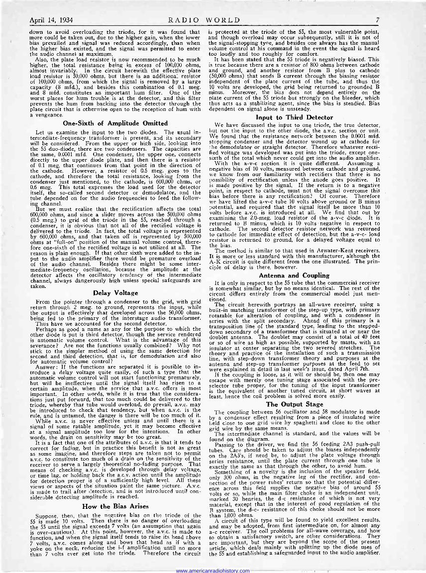
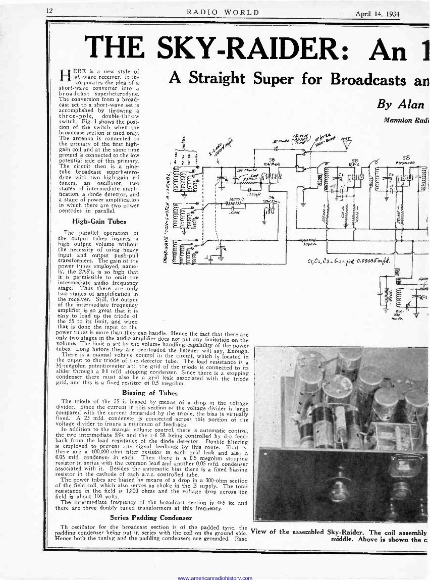
THE SKY -RAIDER: An l HERE is a new style of
all -wave receiver. It in- corporates the idea of a
short-wave converter into a broadcast superheterodyne. The conversion from a broad- cast set to a short-wave set is accomplished by throwing a three -pole, double -throw switch. Fig. 1 shows the posi- tion of the switch when the broadcast section is used only. The antenna is connected to the primary of the first high - gain coil and at the same time ground is connected to the low potential side of this primary. The circuit then is a nine - tube broadcast superhetero- dyne with two high -gain r -f tuners, an oscillator, two stages of intermediate ampli- fication, a diode detector, and a stage of power amplification in which there are two power pentodes in parallel.
High -Gain Tubes
The parallel operation of the output tubes insures a high output volume without the necessity of using heavy input and output push-pull transformers. The gain of the power tubes employed, name- ly, the 2A5's, is so high that it is permissible to omit the intermediate audio frequency stage. Thus there are only two stages of amplification in the receiver. Still, the output of the intermediate frequency amplifier is so great that it is easy to load up the triode of the 55 to its limit, and when that is done the input to the power tubes is more than they can handle. Hence the fact that there are only two stages in the audio amplifier does not put any limitation on the volume. The limit is set by the volume handling capability of the power tubes. Long before they are overloaded the listener will say, Enough. There is a manual volume control in the circuit, which is located in the onput to the triode of the detector tube. The load resistance is a -megohm potentiometer and the grid of the triode is connected to its slider through a 0.1 mfd. stopping condenser. Since there is a stopping condenser there must also be a grid leak associated with the triode grid, and this is a fixed resistor of 0.5 megohm.
Biasing of Tubes The triode of the 55 is biased by means of a drop in the voltage
divider. Since the current in this section of the voltage divider is large compared with the current demanded by the triode, the bias is virtually fixed. A 25 mfd. condenser is connected across this portion of the voltage divider to insure a minimum of feedback.
In addition to the manual volume control, there is automatic control, the two intermediate 58's and the r -f 58 being controlled by d -c feed- back from the load resistance of the diode detector. Double filtering is employed to prevent any signal feedback by this route. That is, there are a 100,000 -ohm filter resistor in each grid leak and also a 0.05 mfd. condenser in each. Then there is a 0.5 megohm stopping resistor in series with the common lead and another 0.05 mfd. condenser associated with it. Besides the automatic bias there is a fixed biasing resistor in the cathode of each a.v.c. controlled tube.
The power tubes are biased by means of a drop in a 300 -ohm section of the field coil, which also serves as choke in the B supply. The total resistance in the field is 1,800 ohms and the voltage drop across the field is about 100 volts.
The intermediate frequency of the broadcast section is 465 kc and there are three doubly tuned transformers at this frequency.
Series Padding Condenser
A Straight Super for Broadcasts an
By Alan
-- a"1 f !
i4
g! n,.sr.
58 SW Mod
Th oscillator for the broadcast section is of the padded type, the View of padding condenser being put in series with the coil on the ground side. Hence both the tuning and the padding condensers are grounded. Ease
/I% d'CRF/d 6,(5.46,(5.4lADJ4
QP7 ;wi5e AMF
Mannion Radi
513 MODuuIEß IzF i
e3 z. N n/ed (1:00o9e7.0P.
58
5
the assembled Sky -Raider. The coil assembly middle. Above is shown the c
www.americanradiohistory.com
April 14, 1934 RADIO WORLD 13
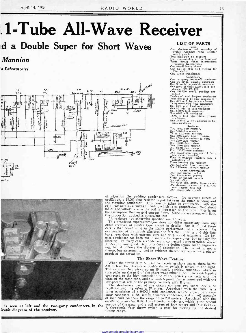
.1 -Tube All -Wave Receiver Ld a Double Super for Short Waves Mannion 'o Laboratories
58
2..5 el? 25Y
is seen at left and the two -gang condensers in ircuit diagram of the receiver.
the
4
aewF co' 2,45 .2A5
LIST OF PARTS Coils
One short-wave coil assembly of twelve windings with selector switch attached
Two high -gain r -f couplers One three -winding r -f oscillator coil Three doubly tuned intermediate
frequency transformers One 80 -millihenry choke One 300-1500 ohm field winding for
filter choke One power transformer
Condensers One two -gang 140 mmfd. condenser One 100 mmfd. variable condenser One 80 mmfd. adjustable condenser One gang of three 0.00035 mfd. con-
densers (Cl, C2, C3) One 800-1350 mmfd. padding con-
denser Twelve 0.1 mfd, by-pass condensers Four 0.05 mfd. by-pass condensers One 0.25 mfd. by-pass condenser Three 0.0001 mfd, fixed condensers One 0.001 mfd. fixed condenser One 0.5 mid. by-pass condenser One 0.00025 mfd. condenser One 0.002 mfd. condenser Three 8 mfd. electrolytic by-pass
condensers One 25 mfd. 25 volt electrolytic by-
pass condenser Resistors
Two 10,000 -ohm resistors One 1,000 -ohm resistor Three 2,000 -ohm resistors One 2,000 -ohm, 2 -watt resistor One 2,500 -ohm resistor (1 watt) One 5,000 -ohm resistor One 40,000 -ohm resistor One 25,000 -ohm resistor One 50,000 -ohm resistor Four 100,000 -ohm resistors One 100,000 -ohm tone control (with
line switch attached) Four %-megohm resistors (one a
potentiometer) Three 500 -ohm bias resistors One 8,000 -ohm, 3 -watt resistor One 7,500 -ohm, 10 -watt resistor
Other Requirements One four -contact socket Two five -contact sockets Eight six -contact sockets Six grid clips One three -pole, double throw switch One dynamic speaker with 300-1500
ohm tapped field coil One eleven -tube chassis
of adjusting the padding condensers follows. To prevent excessive oscillation, a 10,000 -ohm resistor is put between the tuned winding and the stopping condenser. This resistor taken in conjunction with the grid leak acts as a voltage divider, which is so proportioned that about 0.8 of the voltage across the coil is impressed on the tube. This is on the assumption that no grid current flows. Since some current will flow, the proportion applied is somewhat less. All resistors not otherwise specified are 0.5 watt. This broadcast superheterodyne does not differ essentially from any other receiver of similar type except in details. But it is just these details that count most in the stable performance of a receiver. An examination of the circuit discloses the fact that filtering and shielding have been done with extreme care and with sound judgment. No by- pass condenser has been put in merely for appearance, but actually for filtering. In every case a condenser is connected between points where
it does the most good. Not only does the design follow sound engineer- ing, but it follows the dictates of experience. The circuit is not a theory, but an actuality, and in evidence thereof we reproduce a photo- graph of the actual set.
The Short -Wave Feature When the circuit is to be used for receiving short waves, those below
200 meters, the three -pole double throw switch is moved to the right. The antenna then picks tip an 80 mmfd. variable condenser which in turn picks up the grid of the short-wave mixer tube. The switch point connected to the high potential side of the primary connects with the plate of the same tube, and the switch point that is connected with the low -potential side of the primary connects with B plus.
The short-wave part of the circuit contains two tubes, one a 56 oscillator and the other a 58 mixer. Associated with the mixer is a tuner consisting of a 0.00014 mfd. condenser, which is part of a two - gang condenser, a 100 mmfd. trimmer condenser, and a coil assembly of four coils covering the range 10 to 200 meters. Associated with the oscillator is another 0.00014 mfd. tuning condenser, which is the second portion of the gang, and a coil system of four tuners and four ticklers. A three -pole, four throw switch is used for picking up the desired tuning range.
www.americanradiohistory.com
14 RADIO WORLD April 14, 1934
Selected Radio Terms Often Used but Seldom Explained
By Arnold Schaefer
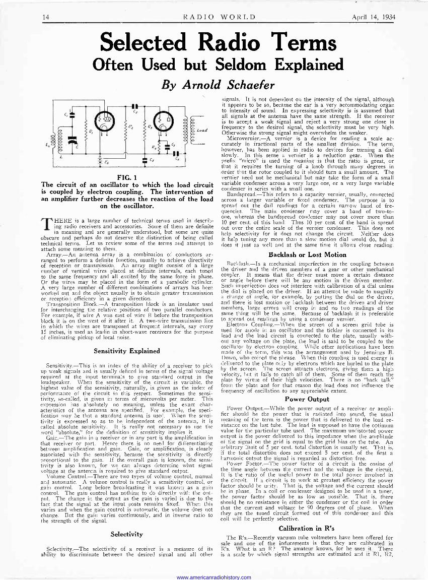
Load
FIG. 1
The circuit of an oscillator to which the load circuit is coupled by electron coupling. The intervention of an amplifier further decreases the reaction of the load
on the oscillator.
THERE is a large number of technical terms used in describ- ing radio receivers and accessories. Some of them are definite in meaning and are generally understood, but some are quite
obscure and perhaps do not deserve the distinction of being called technical terms. Let us review some of the terms and attempt to attach some meaning to them.
Array.-An antenna array is a combination of conductors ar- ranged to perform a definite function, usually to achieve directivity of reception or transmission. An array might consist of a lárge number of vertical wires placed at definite intervals, each tuned to the same frequency and all excited by the same force in phase. Or the wires may be placed in the form of a parabolic cylinder. A very large number of different combinations of arrays has been worked out and the object usually is to obtaiñ greater transmission or reception efficiency in a given direction.
Transposition Block.-A transposition block is an insulator used for interchanging the relative positions of two parallel conductors. For example, if wire A was east of wire B before the transposition block it is on the west of it after it. A two -wire transmission line in which the wires are transposed at frequent intervals, say every 15 inches, is used as leadin in short-wave receivers for the purpose of eliminating pickup of local noise.
Sensitivity Explained
Sensitivity.-This is an index of the ability of a receiver to pick up weak signals and is usually defined in terms of the signal voltage required at the input terminals to give standard output in the loudspeaker. When the sensitivity of the circuit is variable, the highest value of the sensitivity, naturally, is given as the index of performance of the circuit in this respect. Sometimes the sensi- tivity, so-called, is given in terms of microvolts per meter. This expression has absolutely no meaning, unless the exact char- acteristics of the antenna are specified. For example, the speci- fication may be that a standard antenna is used. When the sensi- tivity is expressed so as to be independent of the antenna, it is called absolute sensitivity. It is really not necessary to use the word "absolute," for the definition of sensitivity implies it.
Gain.-The gain in a receiver or in any part is the amplification in that receiver or part. Hence there is no need for differentiating between amplification and gain. Gain, or amplification, is closely associated with the sensitivity, because the sensitivity is directly proportional to the gain. If the overall gain is known, the sensi- tivity is also known, for we can always determine what signal voltage at the antenna is required to give standard output.
Volume Control.-There are two types of volume control, manual and automatic. A volume control is really a sensitivity control, or gain control. Long before broadcasting it was known as a gain control. The gain control has nothing to do directly with the out- put. The change in the output as the gain is varied is due to the fact that the signal at the input posts remains fixed. When this varies and when the gain control is automatic, the volume does not change. But the gain varies continuously, and in inverse ratio to the strength of the signal.
Selectivity
Selectivity.-The selectivity of a receiver is a measure of its ability to discriminate between the desired signal and all other
signals. It is not dependent on the intensity of the signal, although it appears to be so, because the ear is a very accommodating organ to intensity of sound. In expressing selectivity is is assumed that all signals at the antenna have the same strength. If the receiver is to accept a weak signal and reject a very strong one close in frequency to the desired signal, the selectivity must be very high. Otherwise the strong signal might overwhelm the weaker.
Microvernier.-A vernier is a device for reading a scale ac- curately in fractional parts of the smallest division. The term, however, has been applied in radio to devices for turning a dial slowly. In this sense a vernier is a reduction gear. When the prefix "micro" is used the meaning is that the ratio is great, or that it requires the turning of a knob through many degrees in order that the rotor coupled to it should turn a small amount. The vernier need not be mechanical but may take the form of a small variable condenser across a very large one, or a very large variable condenser in series with a small one.
Bandspread.-This refers to a capacity vernier, usually, connected across a larger variable or fixed condenser. The purpose is to spread out the dail readings for a certain narrow band of fre- quencies. The main condenser may cover a band of two -to - one, whereas the bandspread condenser may not cover more than 10 per cent. of this band. Thus 10 per cent. of the band is spread out over the entire scale of the vernier condenser. This does not help selectivity for it does not change the circuit. Neither does it help tuning any more than a slow motion dial would do, but it does it just as well and at the same time it allows close reading.
Backlash or Lost Motion Backlash.-Is a mechanical imperfection in the coupling between
the driver and the driven members of a gear or other mechanical coupler. It means that the driver must move a certain distance or angle before there will be any motion in the driven member. Such imperfection does not interfere with calibration of a dial unless the dial is placed on the driver. If an attempt be made to magnify a change of angle, for example, by putting the dial on the driver, and there is lost motion or backlash between the driven and driver members, large errors will creep in and no two readings of the same thing will be the same. Because of backlash it is preferable to spread out readings by using a condenser vernier.
Electron Coupling.-When the screen of a screen grid tube is used for anode in an oscillator and the tickler is connected in its lead and the load circuit is connected to the plate, usually with- out any voltage on the plate, the load is said to be coupled to the oscillator by electron coupling. While other applications have been made of the term, this was the arrangement used by Jennings B. Down, who coined the phrase. When this coupling is used energy is delivered to the plate only by electrons which are hurled to the plate by the screen. The screen attracts electrons, giving them a high velocity, but it fails to catch all of them. Some of them reach the plate by virtue of their high velocities. There is no "back talk" from the plate and for that reason the load does not influence the frequency of oscillation to any appreciable extent.
Power Output Power Output.-While the power output of a receiver or ampli-
fier should be the power that is radiated into sound, the usual meaning of the term is the power that is delivered to the load re- sistance on the last tube. The load is supposed to have the optimum value for the particular tube used. The maximum undistorted power output is the power delivered to this impedance when the amplitude of the signal on the grid is equal to the grid bias on the tube. An arbitrary limit of 5 per cent. total distortion is usually set. That is, if the total distortion does not exceed 5 per cent. of the first a harmonic output the signal is regarded as distortion free.
Power Factor.-The power factor of a circuit is the cosine of the time angle between the current and the voltage in the circuit. It is the ratio of the useful power to the total power involved in the circuit. If a circuit is to work at greatest efficiency the power factor should be unity. That is, the voltage and the current should be in phase. In a coil or condenser designed to be used in a tuner, the power factor should be as low as possible. That is, there should be no resistance in either the condenser or the coil in order that the current and voltage be 90 degrees out of phase. When they are the tuned circuit formed out of this condenser and this coil will be perfectly selective.
Calibration in R's The R's.-Recently vacuum tube voltmeters have been offered for
sale and one of the inducements is that they are calibrated in R's. What is an R? The amateur knows, for he uses it. There is a scale by which signal strengths are estimated and it R1, R2,
www.americanradiohistory.com
April 14, 1934 RADIO WORLD 15
One c yc/e One period
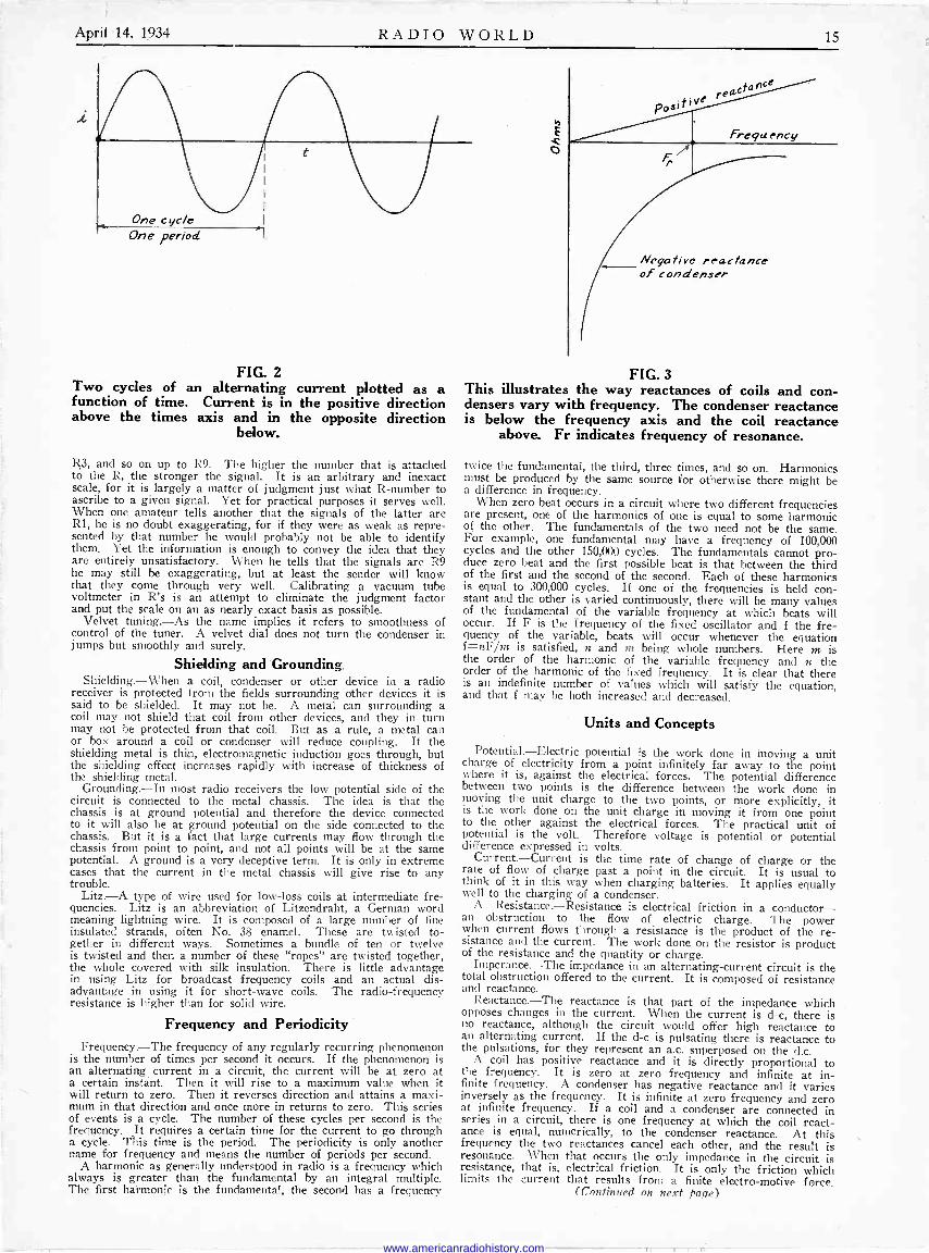
FIG. 2 Two cycles of an alternating current plotted as a function of time. Current is in the positive direction above the times axis and in the opposite direction
below.
R3, and so on up to R9. The higher the number that is attached to the R, the stronger the signal. It is an arbitrary and inexact scale, for it is largely a matter of judgment just what R -number to ascribe to a given signal. Yet for practical purposes it serves well. When one amateur tells another that the signals of the latter are R1, he is no doubt exaggerating, for if they were as weak as repre- sented by that number he would probably not be able to identify them. Yet the information is enough to convey the idea that they are entirely unsatisfactory. When he tells that the signals are R9 he may still be exaggerating, but at least the sender will know that they come through very well. Calibrating a vacuum tube voltmeter in R's is an attempt to eliminate the judgment factor and put the scale on an as nearly exact basis as possible.
Velvet tuning.-As the name implies it refers to smoothness of control of the tuner. A velvet dial does not turn the condenser in jumps but smoothly and surely.
Shielding and Grounding Shielding.-When a coil, condenser or other device in a radio
receiver is protected from the fields surrounding other devices it is said to be shielded. It may not be. A metal can surrounding a coil may not shield that coil from other devices, and they in turn may not be protected from that coil. But as a rule, a metal can or box around a coil or condenser will reduce coupling. If the shielding metal is thin, electromagnetic induction goes through, but the shielding effect increases rapidly with increase of thickness of the shielding metal.
Grounding.-In most radio receivers the low potential side of the circuit is connected to the metal chassis. The idea is that the chassis is at ground potential and therefore the device connected to it will also be at ground potential on the side connected to the chassis. But it is a fact that large currents may flow through the chassis from point to point, and not all points will be at the same potential. A ground is a very deceptive term. It is only in extreme cases that the current in the metal chassis will give rise to any trouble.
Litz.-A type of wire used for low -loss coils at intermediate fre- quencies. Litz is an abbreviation of Litzendraht, a German word meaning lightning wire. It is composed of a large number of fine insulated strands, often No. 38 enamel. These are twisted to- gether in different ways. Sometimes a bundle of ten or twelve is twisted and then a number of these "ropes" are twisted together, the whole covered with silk insulation. There is little advantage in using Litz for broadcast frequency coils and an actual dis- advantage in using it for short-wave coils. The radio -frequency resistance is higher than for solid wire.
Frequency and Periodicity Frequency.-The frequency of any regularly recurring phenomenon
is the number of times per second it occurs. If the phenomenon is an alternating current in a circuit, the current will be at zero at a certain instant. Then it will rise to a maximum value when it will return to zero. Then it reverses direction and attains a maxi- mum in that direction and once more in returns to zero. This series of events is a cycle. The number of these cycles per second is the frequency. It requires a certain time for the current to go through a cycle. This time is the period. The periodicity is only another name for frequency and means the number of periods per second.
A harmonic as generally understood in radio is a frequency which always is greater than the fundamental by an integral multiple. The first harmonic is the fundamental, the second has a frequency
rea,eta nce
Pos¡tiv t
Frequency
Negative reactance of condenser
FIG. 3 This illustrates the way reactances of coils and con- densers vary with frequency. The condenser reactance is below the frequency axis and the coil reactance
above. Fr indicates frequency of resonance.
twice the fundamental, the third, three times, and so on. Harmonics must be produced by the same source for otherwise there might be a difference in frequency.
When zero beat occurs in a circuit where two different frequencies are present, one of the harmonics of one is equal to some harmonic of the other. The fundamentals of the two need not be the same. For example, one fundamental may have a frequency of 100,000 cycles and the other 150,000 cycles. The fundamentals cannot pro- duce zero beat and the first possible beat is that between the third of the first and the second of the second. Each of these harmonics is equal to 300,000 cycles. If one of the frequencies is held con- stant and the other is varied continuously, there will be many values of the fundamental of the variable frequency at which beats will occur. If F is the frequency of the fixed oscillator and f the fre- quency of the variable, beats will occur whenever the equation f=nF/m is satisfied, n and in being whole numbers. Here m is the order of the harmonic of the variable frequency and n the order of the harmonic of the fixed frequency. It is clear that there is an indefinite number of values which will satisfy the equation, and that f may be both increased and decreased.
Units and Concepts
Potential.-Electric potential is the work done in moving a unit charge of electricity from a point infinitely far away to the point where it is, against the electrical forces. The potential difference between two points is the difference between the work done in moving the unit charge to the two points, or more explicitly, it is the work done on the unit charge in moving it from one point to the other against the electrical forces. The practical unit of potential is the volt. Therefore voltage is potential or potential difference expressed in volts.
Current.-Current is the time rate of change of charge or the rate of flow of charge past a point in the circuit. It is usual to think of it in this way when charging batteries. It applies equally well to the charging of a condenser.
A Resistance.-Resistance is electrical friction in a conductor- an obstruction to the flow of electric charge. The power when current flows through a resistance is the product of the re- sistance and the current. The work done on the resistor is product of the resistance and the quantity or charge.
Imperance.-The impedance in an alternating -current circuit is the total obstruction offered to the current. It is composed of resistance and reactance.
Reactance.-The reactance is that part of the impedance which opposes changes in the current. When the current is d -c, there is no reactance, although the circuit would offer high reactance to an alternating current. If the d -c is pulsating there is reactance to the pulsations, for they represent an a.c. superposed on the d.c.
A coil has positive reactance and it is directly proportional to the frequency. It is zero at zero frequency and infinite at in- finite frequency. A condenser has negative reactance and it varies inversely as the frequency. It is infinite at zero frequency and zero at infinite frequency. If a coil and a condenser are connected in series in a circuit, there is one frequency at which the coil react- ance is equal, numerically, to the condenser reactance. At this frequency the two reactances cancel each other, and the result is resonance. When that occurs the only impedance in the circuit is resistance, that is, electrical friction. It is only the friction which limits the current that results from a finite electro -motive force.
(Continued on next page)
www.americanradiohistory.com

16 RADIO WORLD April 14, 1934
A Slide -Back Type Vacuum Tube Voltmeter I. l`lfd
o rah Input
Any Frey. 9
By John C. H. Worcester S6
FIG. 1
The circuit of a slide -back vacuum -tube voltmeter with its own power supply. Voltages are measured in terms of the drop across a potentiometer.
ASLIDE -BACK vacuum -tube voltmeter is a handy device to have around the radio laboratory. A device of this kind to be real handy should have its own B supply so that to
get it ready for use all that is necessary is to plug in the cord into the nearest outlet. When the circuit is arranged in that manner the vacuum tube voltmeter becomes just as convenient as any other voltmeter.
There are several types of vacuum tube voltmeter. One is the so-called slide -back meter, which measures peaks of alternating voltages and as well as d -c voltages. Another type is the direct reading instrument, which may be calibrated either to read r.m.s. alternating voltages or peak values. Then we may have current -drawing instruments as well as non -current drawing meters. For precise work, the meter should be non -current drawing. However, for practical purposes it is all right to per- mit some current to flow, provided this current is very small. It is only when measuring the voltage across highly selective cir- cuits that small currents affect the voltage measured. This does not apply to oscillators, that is, to measurement of - voltages across oscillator tuners. There may be a high voltage across the circuit notwithstanding that there is a comparatively low resistance in parallel with. Therefore if a very high resistance is added in parallel with the resistance already across the circuit, the voltage will not be changed appreciably. But when the voltage is measured across a passive circuit, such as a resonator used in a receiver, even a small current through a shunt re- sistance might change the voltage considerably.
The Slide -Back Meter In Fig. 1 we have a convenient slide -back vacuum -tube volt-
meter designed and built by Alan Mannion. For rectifier a 280 is used and this is fed by the usual power transformer. Also, the usual B supply filter is provided. This part of the circuit is of no particular interest just so it is present in the device and supplies the required filtered voltages.
The vacuum tube employed in the voltmeter is a 56. It has a fixed, or nearly fixed, plate voltage of 75 volts, determined by resistance R6, which should have a value of 7,500 ohms. In the grid circuit is a variable resistance R5 of 2,500 ohms which serves to provide an adjustable grid bias. The maximum drop in this resistance is 25 volts, which biases the tube nearly to the cut-off point.
In series with the voltage divider R5, R6 is a 25,000 -ohm po- tentiometer R4. The maximum drop in this will be 250 volts, and this is the limit of the voltages that can be measured with the instrument without resorting to accessories.
Manipulation of Circuit In the grid circuit of the 56 is a press -button switch P.B.
When this is pressed down the unknown voltage is removed from the grid circuit and the bias provided by R5 alone is on the grid. With the button down R5 is adjusted until the milli - ammeter in the plate circuit reads some low value-the lowest that can be read with certainty and a value that can be duplicated with precision. That is, a division point on the scale should be selected.
When the press -button switch is released, an additional volt- age is impressed on the grid, assuming that the switch across the grid condenser is closed. The value of the added voltage depends on the setting of the slider on R4 and also on what
Definitions of Recurrent Terms (Continued from Preceding Page)
Susceptance.-The susceptance is the reciprocal of the reactance. Therefore the susceptance of a condenser varies directly as the _frequency and the susceptance of a coil varies inversely as the frequency.
Magnetic Ideas Magneto -motive force.-When a current flows through a wire
wound around an iron core, the core is magnetized, and the mag- netization depends on the intensity of the current. The force that produces the magnetic flux in the core is called magneto -motive. The power engineer speaks of magneto -motive force as ampere - turns.
Magnetic flux corresponds to current. Reluctance is the re- sistance equivalent, that is, reluctance opposes the flow of magnetism. The relation among magneto -motive force, magnetic flux, and re- luctance is the same as that among electro -motive force, current,
and resistance. It is an Ohm's law for magnetic circuits. Permeability.-Some materials, especially those containing iron,
nickel, and cobalt, are more easily magnetized than other materials. That is, for a given magneto -motive force a greater flux will result. The reluctance of the magnetic circuit is lower by a certain factor when the core consists of one of these magnetic materials. This factor is the permeability of the substance. If the reluctance of a magnetic circuit is R when the coil is wound on air, it becomes R/µ when the entire core is made of a material having a permeability µ. The permeability for any given magnetic material is not a constant, but depends on the flux. If there is an air gap in the magnetic circuit, this gap reduces the effective permeability of the circuit for even a short gap will have a very high reluctance compared with the reluctance of the magnetic material, especially if that material is soft iron and certain alloys of iron and nickel, the so- called permalloys.
www.americanradiohistory.com
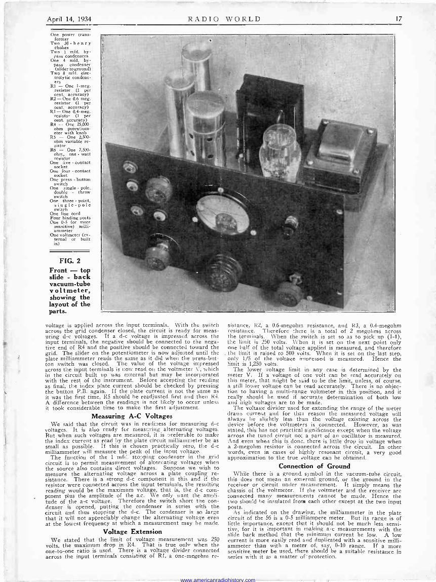
April 14, 1934 RADIO WORLD 17
One power trans- former
Two 30 -henry chokes
Two 1 mfd. by- pass condensers
One 4 mfd. by- pass condenser (slider to ground)
Two 8 mfd. elec- trolytic condens- ers
Rl - One 1-meg. resistor (1 per cent. accuracy)
R2 - One 0.6 meg. resistor (1 per cent. accuracy)
R3 - One 0.4-meg. resistor (1 per cent. accuracy)
R4 - One 25,000 - ohm potentiom- eter with knob
RS - One 2,500 - ohm variable re- sistor
R6 - One 7,500 - ohm, one - watt resistor
One five - contact socket
One four - contact socket
One press - button switch
One single - pole. double - throw switch
One three - point, single -pole switch
One line cord Four binding posts One 0-5 (or more
sensitive) milli - ammeter
One voltmeter (ex- ternal or built in)
FIG. 2
Front - top slide - back vacuum -tube voltmeter, showing the layout of the parts.
voltage is applied across the input terminals. With the switch across the grid condenser closed, the circuit is ready far meas- uring d -c voltages. If a d -c voltage is impressed across the input terminals, the negative should be connected to the nega- tive end of R4 and the positive should be connected toward the grid. The slider on the potentiometer is now adjusted until the plate milliammeter reads the same as it did when the press -but- ton switch was closed. The value of the voltage impressed across the input terminals is now read on the voltmeter V, which in the circuit built up was external but may be incorporated with the rest of the instrument. Before accepting the reading as final, the index plate current should be checked by pressing the button P.B. again. If the plate current is not the same as it was the first time, R5 should be readjusted first and then R4. A difference between the readings is not likely to occur unless it took considerable time to make the first adjustment..
Measuring A -C Voltages We said that the circuit was in readiness for measuring d -c
voltages. It is also ready for measuring alternating voltages. But when such voltages are measured, it is preferable to make the index current as read by the plate circuit milliammeter be as small as possible. If this is chosen practically zero, the d -c milliammeter will measure the peak of the input voltage.
The function of the 1 mfd. stopping condenser in the grid circuit is to permit measurement of alternating voltages when the source also contains direct voltages. Suppose we wish to measure the alternating voltage across a plate coupling re- sistance. There is a strong d -c component in this and if the resistor were connected across the input terminals, the resulting reading would be the maximum voltage, that is, the d -c com- ponent plus the amplitude of the a.c. We only want the ampli- tude of the a -c voltage. Therefore the switch short the con- denser is opened, putting the condenser in series with the circuit and thus stopping the d -c. The condenser is so large that it will not appreciably change the alternating voltage even at the lowest frequency at which a measurement may be made.
Voltage Extension We stated that the limit of voltage measurement was 250
volts, the maximum drop in R4. That is true only when the one-to-one ratio is used. There is a voltage divider connected across the input terminals consisting of R1, a one-megohm re-
sistance, R2, a 0.6-megohm resistance, and R3, a 0.4-megohm resistance. Therefore there is a total of 2 megohms across the terminals. When the switch is set so as to pick up (1-1), the limit is 250 volts. When it is set on the next point only one half of the total voltage applied is measured, and therefore the limit is raised to 500 volts. When it is set on the last step, only 1/5 of the voltage impressed is measured. Hence the limit is 1,250 volts.
The lower voltage limit in any case is determined by the meter V. If a voltage of one volt can be read accurately on this meter, that might be said to be the limit, unless, of course, a still lower voltage can be read accurately. There is no objec- tion to having a multi -range voltmeter in this position, and it really should be used if accurate determination of both low and high voltages are to be made.
The voltage divider used for extending the range of the meter draws current and for that reason the measured voltage will always be slightly less than the voltage existing across the device before the voltmeters is connected. However, as was stated, this has not practical significance except when the voltage across the tuned circuit not a part of an oscillator is measured. And even when this is done, there is little drop in voltage when a 2-megohm resistor is connected across the circuit. In other words, even in cases of highly resonant circuit, a very good approximation to the true voltage can be obtained.
Connection of Ground While there is a ground symbol in the vacuum -tube circuit,
this does not mean an external ground, or the ground in the receiver or circuit under measurement. It simply means the chassis of the voltmeter. If the voltmeter and the receiver are connected many measurements cannot be made. Hence the two should be insulated from each other except at the two input posts.
As indicated on the drawing, the milliammeter in the plate circuit of the 56 is a 0-5 milliampere "meter. But its range is of Iittle importance, except that it should not be much less sensi- tive, for it is important in making a -c measurements with the slide back method that the minimum current be low. A low current is more easily read and duplicated with a sensitive milli - ammeter than with a meter of, say, 0-10 range. If a more sensitive meter be used, there should be a suitable resistance in series with it as a matter off -protection.
www.americanradiohistory.com

18 RADIO WORLD April 14, 1934
A Neon Audio Oscillator Connections for Modulating an R -F Oscillator
A neon oscillator modulating an r -f In this circuit the connection from oscillator, by connection of the neon the neon oscillator circuit is made
circuit to the grid of the triode. to the plate of the triode. THE neon tube as an audio oscillator serves admirably the
purposes of modulation in a test oscillator. That object is fully achieved even with the smallest -powered neon lamp
commercially made, a small fraction of a watt. The oscillation intensity is sufficient, there is no danger of overmodulation if the correct connections are made to the radio -frequency oscilla- tor, and the nuisance of having a high -resistance leak as a blocking device to cause the r -f oscillator also to generate audio frequencies is avoided.
The introduction of a separate modulator tube is advantageous because then the selectivity may be practically uniform over the tuning range or ranges, and zero beating always is possible. While the actual value of zero beating may be small, especially to those who use the modulated oscillator to measure and peak r -f and i -f channels, nevertheless the fact that it can zero beat at all and any settings is a compliment to the oscillator. It means that the damping is not so high as to drown the zero beat, which is actually present though not heard.
How Shall Introduction Be Made? While zero beating is mentioned, all audio beating is really
meant, for when the circuit is properly proportioned there will be audio frequencies heard when the test oscillator is worked in conjunction with a receiver which is bringing in a broadcast- ing station, whether beating is with the carrier of the station itself, the local oscillator or with the intermediate frequency, which is also an oscillating frequency, although not particularly so regarded by many.
The problem is to introduce the modulation from the neon lamp in such a manner as to avoid over -modulation, avoid absence of audio oscillation, avoid detuning effects on the tuned circuit, and avoid the tuning condenser changing the pitch of the audio oscillation.
But before three is any trouble of this type first there must be audio oscillation so let us state that values will produce it nicely.
The neon tube will strike at around 76 volts or so, and any voltage applied in excess of this simply produces more glow, greater current through the lamp and small frequency change! However, the oscillation is present by virtue of the interrup- tion of the current flow, and there must be a charging current which does not exceed the minimum discharge current. Various combinations will effectuate this, but then the frequencies of oscillation will differ. For instance, the frequency may be as low as 1 cycle per second, which is entirely too low for modu- lating purposes. The frequency may be raised either by raising the series resistor or decreasing the capacity across the lamp.
Access to Lamp Itself Many of the lamps now used have a series resistor built in,
around 100,000 ohms, hence access to the lamp terminals proper is not possible, without removing the resistor. If a condenser is put across the base into which the lamp fits, the condenser will be across the series circuit consisting of the neon lamp and the limiting resistor. Audio oscillation may not be reliable under J. B. Bryson, 924 - 7th St., West, Birmingham, Ala. Walter J. Tyczka, 814 Clinton St., Buffalo, N. Y. George Gasoarini, 1436 Hollywood Ave., Chicago,
Ill. Edward Choy, 801 - 18th St., Bakersfield, Calif. Sanger Radio, A. D. S. Goldsman, Mossbury
Works, Mossbury Road, Clapham Junction, Lon- don, S.W. 11, England.
Victor De Ziel, 170 Lafond Street, St. Paul, Minn. Peter Lorino, Lorino Radio Co., 36 Lindsey Court,
Hialeah, Fla. Don Seliga, 250 North Heights, Youngstown, Ohio. John Jarrett, 222 High Street, Lowell, Mass. Geo. B. Thompson, M.D., 2400 West Pico Street,
Los Angeles, Calif. G. R. Hill, Radios and Radio Repairing, Route 1,
Galva, Kans.
NL
Here the modulating frequency is unaffected by tuning and modulation
is always present. such circumstances. It may be present at times, but the audio oscillation may not be always self-starting. However, small devices using pigtail lamps about as long as a thumbnail may be taken apart, particularly a neon -equipped fuse, and the small lamp's resistor removed. Then a condenser of 0.00039 mfd. is put across the lamp, and a limiting resistor of 4.0 meg. is used. The audio frequency thus generated will be around 3,000 cycles, and makes a nice -sounding and distinctive note, which one appreciates for modulation purposes. Moreover, the oscillation intensity of the neon lamp has a steady average that enables output meter readings being taken without confusion due to jumpiness of the needle. The grid -blocking method, that is, high resistance in the leak -condenser circuit of the r -f oscil- lator, produces decidedly wobbly output.
The Shifting Spot With the constants properly chosen, R being 4.0 meg. in the
diagrams, and C being 0.00039 mfd., the neon lamp may be of any wattage. The oscillation amplitude will depend on the dif- ference between the striking and the extinguishing voltages, hence partly on the amount of the voltage applied for any given value of R. However, if not enough is applied, there will be no striking. The resistance of 4.0 meg. is suitable for voltages around 100 volts.
If the tube glows brightly it will not oscillate at an audio frequency, that is, the limiting resistor is entirely too low or voltage applied is too high. Usually the glow concentrates in one corner as a sort of spot, when audio frequency oscillation occurs, although as the capacity or resistance is changed, the spot travels in a spiral course. This denotes a phase shift and might be used by the ingenious experimenter for phase -angle displacement measurement.
It is confessedly hard to find a suitable method of connection for the lamp, especially if a triode is used. If the total voltage available is something around 100 volts, as from the line in a universal type test oscillator, then if the method shown at left is used there will be too high a direct -current voltage on the grid during the conducting period in the neon circuit, and indeed this voltage is itself fluctuating at the audio frequency of oscil- lation, and produces an unsteadiness.
Use With a 34 Tube If the connection is made to the plate from the other side
of the line, as in the central diagram, then too much capacity is introduced in the plate circuit, where it is even more serious than its identical quantity in the preceding example of the grid circuit, because in the plate circuit it might stop oscillation at all radio and certain audio frequencies, or may start parasitic oscil- lations, with confounding results.
The best method found for a universal test oscillator is that used in the commercial model 30 -AB, and is diagramed at right. Here the control grid of a 34 tube is used in the familiar fashion, the screen is used as the effective plate, for feedback, and the erstwhile plate is connected through a low resistance to the negative side of the line. It is called negative because whn a.c.
(Continued on page 20)
Literature Wanted Readers desiring radio literature from manufacturers and jobbers should send a request for publication of their name and address. Address Literature Editor, RADIO WORLD, 145 West 45th Street, New York, N. Y.
Otto Krause, 59 W. Forest Ave., Detroit, Mich. Robert F. Graham, 1461 Carmen Ave., Chicago, Ill.
Eleon M. Shuman, 89 Western Avenue, Waterville, Maine.
Russell Roach, Absaraka, No. Dak. Jose de Paz, Hudson Radio Store, 531 West 145th
St., New York, N. Y. F. R. Bryant, 3948 West End Ave., Chicago, Ill. H. R. Hanson, 701 Bradley St., St. Paul, Minn. Pvt. Luther D. Wilkerson, Veterinary Station
Detachment, Fcrt Sam Houston, San Antonio, Texas.
R. W. Stupp, 231 Hummel Ave., Lemoyne, Penna. S. D. Eilenberg, 14 Reeser Ct., Phillipsburg, N. J. L. H. Veach, c/o Sou. R.R., Union Station, Colum-
bia, S. C. R. L. Stitzel, 529 N. Sunnyside Ave., South Bend,
Ind.
www.americanradiohistory.com

April 14, 1934 RADIO WORLD 19
Remedies for Motorboating Two B Supplies and Individual Filtering of Circuits
Are Aids By Einar Andrews
C3
o
o d
o O o dq
FIG. 1
This is a skeleton form of a five -stage, six -tube, high -gain audio amplifier which illustrates how motorboating occurs in a sensitive amplifier. Two separate B supplies are suggested to stop oscillation.
MOTORBOATING is loose again. For a while we did not have much trouble with it because audio amplifiers used in receivers did not have much gain, or only two stages were
used, one of which was resistance coupled. But high -gain ampli- fiers for public address purposes and other applications are being constructed, amplifiers having as many as five stages. Motorboating is an almost unavoidable consequence of multiplying the number of stages in the amplifier. Let us review the subject in connection with a five -stage amplifier. It might be well to say that we are not describing an amplifier to be built.
The first two tubes in the circuit are screen grid tubes in re- sistance capacity settings. They are capable of high gain and for that reason motorboating is likely to be encountered in the circuit. In a certain amplier built along this line violent motorboating oc- curred when the first tube was in the socket without anything con- nected across the input terminals. When the terminals were shorted, the difficulty was intensified. When a high negative bias was ap- plied to the grid of the first tube, the trouble stopped.
The Way of Feedback These facts point to the way in which the feedback occurs. When
the tube is out of the socket there is no conductive path to ground through R2. Therefore any signal voltage existing across the B supply terminals (B2 and ground) will send a current through R2 This will affect the voltage across the grid resistance R4 and the voltage across this resistance due to the feedback will be amplified by the succeeding tubes. It only requires an infinitesimal amount of feedback to cause sustained oscillation when there is so much amplification as in this circuit.
With tube out of the socket current can flow through R2 but only through C3 and R4. The feedback current through the grid leak will now be out of phase and it will not build up by continued regeneration. The same thing happens when the grid of the first tube is given a high negative bias, for then the plate current in that tube is cut off, and if any feedback current is to flow through R2 it must first go through C3 and then down to ground through R4. That is, when there is a conductive path through the tube there will be a voltage fluctuation across R2 due to the feedback and this will be in correct phase for oscilla- tion, but when the first tube is open for any reason no in -phase feed- back can occur.
First Part Unstable If we consider only the first three tubes in the amplifier, including
the plate circuit of the third tube, we have an unstable amplifier. It is so unstable that it is practically impossible to stop motor - boating. This is especially true when the first two tubes have a high gain.
If we consider only that part of the circuit which contains the two low -mu tubes, that is, the two in the plate circuits of which are primaries of transformers, we have a possible motorboating ampli- fier. But oscillation in this part of the circuit is not like unless the plate circuit of the second tube is affected. Signal current re- sulting from audio voltages across the B supply will back up through the first transformer primary and through the third tube.
If the windings of the transformer are connected in one way there is a possibility of motorboating but if they are connected the op- posite way there will be degeneration in place of regeneration.
When we have four tubes in the amplifier, there is still a greater chance of oscillation, and there is little chance of stopping the racket by reversing leads or by filtering. With the power stage added, one might almost say without roservation that motor - boating cannot be prevented by filtering. While the push-pull stage should not alter the conditions in any way, the fact is that no push-pull amplifier is so well balanced that there will not be some feedback.
Standard Remedies The standard remedy for motorboating is to filter the individual
plate circuits. This is indicated in the plate circuits of the first two tubes. A resistor R3 is connected in series with each coupling resistor R2 between that resistor and the B supply. Then a con- denser C2 is connected between the junction and ground. Unfor- tunately these filters are not effective in all instances, and in this particular case they had no noticeable effect. The gain in the tubes was too high. Of course, it is theoretically possible to use condensers large enough to make the filter effective at even the lowest audio frequency, but when the gain is high, the values of capacity required are so high that it is practically impossible to provide them.
The two filter resistors could be replaced by chokes, and they would be much more effective at the higher frequencies, but it is rarely at the high frequencies that the trouble occurs, for at these it is effectively prevented by the condensers in the B supply filter.
Treatment of Power Stage When the power stage contributes much of the feedback, and
it is always safe to say that it does, some improvement results when the circuit is connected as in this diagram. The plates are fed through high inductance chokes and the primary of the output transformed is connected between the two plates. If there is no ground connection to the primary no stopping condensers are needed. This is advantageous for the low audio frequencies can circulate through the winding without causing any feedback. When the middle of the primary is grounded stopping condensers are needed and when they are used they should be large. Large ca- pacity is not needed so much to insure good quality as to prevent feedback. It is only the feedback that goes through the plate chokes to be B supply that causes any trouble.
These are standard remedies, which are no remedies at all in a circuit as sensitive as this one is. A few tests on the circuit made this clear.
Other Remedies If filtering will not stop motorboating in a circuit, is it necessary
then to avoid high -gain audio amplifiers or are there other means for stopping the trouble? If the difficulty occurs at a very low audio frequency, there is a very simple remedy, and it is about the only one that is effective, for chokes and resistance in the B is on the plate there is conduction only when the plate is posi-
(CQntinued on next page)
www.americanradiohistory.com
20 RADIO WORLD April 14, 1934 (Continued from preceding page)
press noise. I must say that I have tried transposition without any supply leads and by-pass condensers are of little use. That simple remedy is to use smaller stopping condensers in the plate -grid cir- cuits, represented by C3 in Fig. 1.
What do these condensers do? First they stop the d -c from going on to the grid, and second they stop the low frequencies. The lower frequency the more effective is a condenser in stopping the signal, and the smaller the condenser, for a given frequency, the more effective it is in stopping the signal. Therefore if the oscillation occurs on a very low frequency, reducing the size of the stopping condensers will stop the trouble.
Reducing the size of the condensers naturally introduces fre- quency distortion, for they will reduce the gain not on one fre- quency but on all. The reduction is only greater at the lower frequencies. The cut-off is rather sharp so that if the oscillation occurs at a frequency of, say 5 cycles per second, there need not be much reduction of the amplification on the essential audio fre quencies, say those in excess of 25 cycles per second.
This reduction does not necessarily introduce a great deal of distortion, for if the circuit motorboats on a low frequency, the gain at that frequency is excessive and it is also high on neigh- boring frequencies. By just stopping the oscillation it is possible that the gain on the low notes is as high as it ought to be. Whether it is or not cannof be determined except by experiment.
In severe cases of motorboating the only practical way of stopping the trouble is to use separate B supplies for the different parts of the circuit. This does not mean, of course, that there should be one for each tube in the circuit. That would hardly be practical, even though it is desirable. But can use two B supplies to good advantage. One should serve the first two tubes in the circuit, meaning the circuit in Fig. 1 or one like it. There can be no motor - boating in this part of the circuit if that is done, for a two -stage resistance -coupled amplifier is stable.
If a separate B supply is used for the first two tubes, the series resistors R3 are not needed. Neither are the by-pass condensers C2, for there will be sufficient by-pass capacity in the B supply filter.
Should the plate return of the third tube be connected to the same in B supply, it would be very difficult to stop motorboating. Hence that should be connected to the supply of the remaining tubes. Stabilization of the transformer coupled circuit is compara- tively easy.
Since the auxiliary B supply serves only two tubes, and the total current drawn by these tubes is very small, it requires only a small rectifier and small filter chokes. Even the capacities in the filter can be comparatively small. For a rectifier a general purpose tube like the 56 could be used. For a transformer any small power transformer giving a rather high voltage should be employed. For chokes, the secondary or primary windings of an audio trans- former would be all right. However, whether these would be suit- able would depen l on the total current they are required to pass. There may be a bleeder current in the voltage divider that draws as much as the two tubes together. But even so, the total current need not exceed 5 milliamperes. Almost any audio transformer primary would be suitable in that case. A heavy-duty B supply, of course, is needed for the transformer coupled amplifier, especially if 2A3s are used in the output stage. Sometimes motorboating is eliminated by using separate voltage dividers for the different tubes in the circuit. But this is no more effective than the method of using individual filters, for the two are identical, except that when individual voltage dividers are used there is a bleeder for each tube as well as a series resistor or choke. It may be that if separate filters in the B supply are used greater stability will result. But this, too, is equivalent to using individual filters using larger chokes and larger condensers. If this is done and the rectifier employed has a constant voltage drop across it, there should be complete stability. The simplest way of attaining stability, it appears, is to use a separate power supply for a couple of the tubes, especially two
Radio University Answers to Questions of General Interest to Readers. Only Selected Questions are Answered and Only by Publication in These Columns. No Correspondence Can be Un- dertaken.
resistance coupled tubes of high gain to each other, or as in Fig. 1.
* * *
Altering Frequency Changer CAN A FREQUENCY CHANGER consisting of an inter- mediate transformer and a radio -frequency transformer and designed for use with a 57 or a 24 be used, in conjunction with a 2A7? What changes will have to be made if it is practical?-G. F. The condenser that tunes the primary of the i -f transformer is now connected to a tap on the oscillator coil. Remove it and make two independent transformers. That is, connect the condenser directly across the primary. Bring out the eight leads separately. After that has been done the two transformers can be used in any circuit. * * *
Effect of Transposition JUST HOW does transposition of conductors in a leadin sup- press noise? I must say that I have tried transposition without any appreciable improvement in the signal-to-noise ratio.-F.G.K. The transposed leadin does not help against noise that is picked up by the antenna. It only prevents additional pick-up in the leadin. Suppose that in order to get a good signal pick-up you have to run a long leadin past several floors where there are many electrical appliances. All of these appliances are noise transmitters. Not much of the noise gets up to the antenna but considerable of it gets to the leadin. Hence if the leadin is transposed at frequent intervals, the net pick-up by that leadin is practically zero. If the noise originates at a point a long distance away from the antenna the noise will get in to the set regardless of the type of antenna that is used, assuming that it is not sharply directional.
* * *
Microphones WHAT is the difference between a pressure and a velocity microphone? What pressure and what velocity are involved? In what respect is one superior to the other ?-R.H.L. The pressure and velocity are those of the air due to the passage of a sound wave. There is always a certain barometric pressure.
As a sound wave passes there is a change in this pressure. One moment it is higher than the barometric pressure, the next moment it is lower than that pressure. The pressure microphone responds to the variation. Since there is a change in the air pressure, there is also a flow of air from one point to another, a back and forth flow. The rate at which an air particle moves is the velocity. It really amounts to a wind, but instead of direction it is alternating. The velocity microphone responds to the movement of thé air, which means that the responsive element in the microphone must move with the air. The responsive element in a pressure microphone should not move. Yet it is necessary that it move in order that there be any effective. The case is similar to a voltmeter and a current meter. The voltmeter is pressure responsive whereas the current meter is velocity responsive, for voltage is electrical pres- sure and current is electrical velocity. Ordinary direct -reading (Continued on next page)
when they are placed next
Neon Tube Coupling to R -F Oscillator (Continued from page 18)
tive, and during that alteration the side called negative of the line is negative in respect to plate. There is current through this low resistance, even though the element, the conventional plate, is seemingly grounded. The current flow is due of course to the existence of a potential difference across the resistor from plate to line. The plate is associated with the space stream inside the tube and catches some electrons to return them to cathode through this resistor. That they are few is proved by the fact that the voltage drop across this resistance is not sufficient to lower the effective
voltage on the neon lamp to that point where oscillation stops. If the plate were connected to the positive side of the line the neon tube would neither oscillate nor light, because of too much drop in this resistance. Say 10,000 ohms are used. Ai 5 milliamp- eres the drop would be 50 volts, and this would be enough to prevent oscillation.
In practice the resistance from plate to negative line is 10,000 ohms, and it is a potentiometer, so that the output is varied by moving the slider. The frequency generated by the r -f oscillator is not changed, especially as the coupling is elec-
ti on, nor is the frequency of audio oscillation shifted by the rotation of the r -f tuning condenser, because the two oscillators separated by the equivalent high resistance of the electron stream, in fact, by a higher resistance than that, since only a tiny part of the stream runs through this resistor . Considerable experimenting was doen with the model that in- corporates the neon tube, using the values specified, and the results were so compltely satisfactory that they made pos- sible the improvement of the accuracy of the oscillator, besides adding the undeniable advantage of an attenuator, provided the line was blocked. The total circuit of the Model 30 -AB Test Oscillator has been tested and drawn up, with the expectation that it will be printed
in next week's issue, so that .the method of line -blocking, and other interesting facts, will be presented. Also a picture -diagram of the wirink is in preparation and it is hoped this will be ready in a month. At least, it is being prepared for publication, and those interested in test oscillators, especially of the frequency - stabilized type (meaning highly accurate models will want to follow this circuit, which they can built themselves, if they so desire.-Herman Bernard.
www.americanradiohistory.com

April 14, 1934 RADIO WORLD 21
(Continued from preceding page) voltmeters must draw some current. The best voltmeter draws no current and then it is a true pressure -operated device. The velocity microphone has the advantage that it is practically independ- ent of the frequency and one of its disadvantages is that it is not nearly as sensitive as some pressure -operated microphones. But the pressure -operated microphones are not independent of the fre- quency.
* * *
Class B Amplification WHEREIN does Class B amplification differ from push-pull
amplification? It seems to me that the circuits for the two are identical. There must be some distinguishing feature that charac- terizes each type of amplifier.-T.R.M.
In Class A push-pull, both tubes work all the type but in oppo- site phase, one relaxing while the other takes hold. The grids of the two tubes must be biased so that the plate current in each tube can increase as well as decrease, by about the same amount, and so that at no signal both draw about the same plate current. In Class B, on the other hand, only one tube works at a time. One tube handles one side of the signal and the other tube the other side. Each of the tubes in a Class B amplifier is a grid bias de- tector biased to the cut-off or very near that point. The output consists of two current pulses per cycle. These are combined in the output transformer so as to produce a regular wave. In the Class B amplifier no plate current flows in either tube when there is no signal. It is for this reason that the Class B amplifier is
much more efficient than the Class A. * * *
U. S. Standard Frequency WHAT KIND of receiver is required for picking up the 5,000 -
cycle standard transmitted by the Bureau of Standards? How can it be identified? If this cannot be picked up, can the broadcast stations be relied on as standards of frequency?-W.E.j.
Any short-wave receiver should be sensitive enough to pick up the Government transmission, provided that receiver reasonably sensitive. Get an approximate calibration of the receiver and then try to receive the standard frequency on the dial setting where it is
supposed to come in. It will not be far off. Remember that the standard frequency is only on the air at certain times, Tuesdays from 12 noon to 2 p.m. and from 8 p.m. to 10 p.m. Announcements are made in code. Locate it by the approximate calibration and the time of day if you cannot read code. Broadcast stations can be relied on for all practical purpose of calibration, especially the larger stations below 1,000 kc. They are held very closely to the frequencies assigned them.
* * *
Precision Voltmeter RECENTLY I acquired a wall type galvanometer provided with
a long scale and a telescope. It is extremely sensitive as I can detect current through 100 megohms. I have wondered if this galvanometer could not be used for a precision voltmeter, one that draws practically no current. If so, how can it be done?-W.E.C.
Yes, it can be used as a voltmeter as well as a current meter. If you use it as a voltmeter it is necessary to calibrate it against known voltages, using series resistors that do not change with current or with temperature. You might calibrate it against a voltmeter that does draw current, for if the two are across the same voltage at the same time, the current drawn does not make any difference. The calibration will be no better than the accuracy of the instrument you use for calibrating against. Moreover, it is
difficult to get good high resistances at reasonable cost. It is quite likely that the resistances will cost more than the galvanometer.
* *
Swamping Small Stations WILL THERE not be danger of swamping all the small broad-
cast stations as well as some of the larger ones when the 500 -kw station WLW gets going? This is a power ten times higher than any station now operating and even now some of the larger stations interfere with the small stations.-L.H.Y.
It is only those who live close to the super -power stations that are likely to have much trouble of this nature. Experience has
shown that increase of power does not greatly increase the inter- ference range, although it does increase the reliable coverage range. This fact, of course, is directly due to the fact that modern receivers are extremely selective. A few years ago a 500 -kw station would have blanketed nearly all other stations over a wide area and a
wide frequency range. The station will never go on the air with 500 kilowatts if there is much interference from it. The Federal Radio Commission will see to that.*
*
Capacity and Inductance Measurements AS I DESIRE to have some measuring equipment, not necessar-
ily 'of the precision type, but good enough for a conscientious ex- perimenter, what would you advise in respect to measurements of
inductance and capacity ?-R. W. It is highly advisable that you have a calibrated condenser. This
type is usually of the straight line capacity type, so that equal dif-
ferences on the dial always will represent equal differences in capac- ity. If you can not afford a calibrated condenser you could calibrate your own, using a 56 tube as oscillator, grid -leak fashion. With values of 500,000 ohms for series leak, 0.00005 mfd. for grid con-
denser. plate voltage around 100, and grid returned to cathode, a
commercially -obtainable honeycomb coil, costing about 60 cents,
will give you a closely accurate inductance of 25 millihenries. The distributed capacity of this universal -wound inductance may be ne- glected, since it is around 1.0 mmfd. Provide a tickler. The sec- ondary coil is used in conjunction with the unknown condenser. By keeping wiring leads short the circuit capacity amounts to 10 mmfd. By the relationship of frequency to capacity for the stated induc- tance the total capacities are ascertained. Deduct 10 mmfd. for the circuit capacity alone, leaving the net as the condenser capacity. The total capacities, related to frequencies for this inductance, include 50 kc=410 mmfd., 60 kc=285 mmfd., 70 kc=210 mmfd., 80 kc= 160 mmfd., 100 kc=105 mmfd., 120 kc=70 mmfd,, 140 kc=52 mmfd., and 170 kc=29 mmfd. For the condenser alone the values would be 400 mmfd., 275 mmfd., etc. The frequencies may be identified by beating with a t -r -f receiver that brings in broadcasting stations, as harmonics will be generated by the oscillator. By substituting other coils, once the capacity settings are known, the unknown inductance may be determined from the formula for inductance. We recently published a simplification of the inductance -determining method, ap- plied to the capacities at two settings, one representing twice the frequency of the other. Let F be the lower frequency, then the inductance in henries is 0.019/(C1-Cs) Fs For microhenries move the decimal point six places to the left. Cl and C2 are obtained from the calibrated condenser by adding 10 mmfd. to the condenser calibration alone. Also, the minimum capacity of the total circuit, including condenser, may be verified from the formula Co=(CI.- 4C2)/3, where, again C1 and C2 are the two capacities present at any two frequencies thus harmonically related. The answer is in farads. Move the decimal point six places to the left for micro- microfarads.
* * *
Oscillator Suppressor THE GRID SUPPRESSOR has been used in the past for
squelching oscillations, but I find now that it is included also in os- cillators, where, it would seem, oscillations should not be squelched. Please explain.-K. D.
The reason for the grid suppressor in test oscillators, or local oscillators in superheterodynes, is to increase the capacity reactance at the higher frequencies, where otherwise the oscillation intensity would be too strong, because the coupling of tickler makes it so. If the coupling is made looser it may be too loose for the lower fre- quencies. Therefore the coupling is selected for the low -frequency value, and in the grid -leak type oscillator the result will be a uni- form amplitude over most of the scale, until high frequencies of the tuning range are reached or approached, when the damping effect of the series resistor becomes strong. Thus the amplitude may be flat- tened, that is, the intensity of oscillation is uniform, which is desirable.
* * *
Choice of Coupling Condenser WHEN A STOPPING condenser is used in an audio -frequency
circuit in series with a transformer winding for the purpose of keep- ing the d.c. out of that winding, what should its value be? Is it suf- ficient to use one of the order or 0.01 mfd. or should it be 100 times as large ?-G. H. L.
What size the condenser should be depends first on the lowest fre- quency that should be amplified fully and second on the impedance with which that condenser is in series. Suppose the transformer winding has an impedance of 100,000 ohms at 50 cycles per second. At this frequency the condenser reactance should not be more than, say, 1 per cent. as large as the transformer winding impedance. This would require a condenser of 3.18 mfd. If the impedance of the transformer winding is less than the specified value the conden- ser would have to be larger in proportion. If it is not necessary to amplify the 50 -cycle frequency to such a high degree, the con- denser may be smaller. If the transformer delivers power to a loud- speaker or to a driver stage, the impedance will not be nearly as high as the value specified above, and then the condenser would have to be much larger. Otherwise, the low notes would suffer a great reduction in amplification.
* * *
About a Cage Aerial WHAT ADVANTAGE has a cage antenna over a straight wire
antenna? If all the wires are joined at their ends, I cannot see how the length of this antenna becomes, say, 100 feet if five wires of 20 feet each are used. I have tried one of these cag atnennas and find reception better at certain wavelengths but not the same at different wavelengths. Can you account for the above?-A. J. Vitale, East Rutherford, N. J.
If each wire is 20 feet long, any number of equal wires connected in parallel will make a conductor 20 feet long. But five wires will have much less radio -frequency resistance than one wire of the same diameter. That is one advantage. The inductance of the antenna will also be different. If the individual wires are far enough apart, the inductance of the combination will be about one -fifth, since that is the law by which non -coupled inductances combine. This does not change the inductance of the lead-in of course. Another differ- ence is that the capacity of the antenna will be increased in about the ratio of the increase in the number of the wires. This makes the current in the lead-in more nearly uniform, which is supposed to make the antenna a much better radiator. By reciprocity it would also make it a better receiver. Any antenna, of course, is best at one particular frequency. Changing from one to five wires would only change the frequency at which it is best.
www.americanradiohistory.com
2.% RADIO WORLD April 14, 1934
Station Sparks By Alice Remsen
SPRING CHANGES ON THE MICROPHONE With the Spring come changes in radio schedules. Horlick's Adventures in Health, featuring Doctor Herman N. Bundeson, president of the Chicago Board of Health and
nationally known public health authority, has started a new schedule, and will be heard only once a week, on Sundays at 9:45 p.m., NBC-WJZ net work.... Several new pro- grams have opened over NBC. Lulu Vollmer, whose "Moonshine and Honeysuckle" series was such a favorite for two years, is back again with a new series called "Grits and Gravy." Robert Strauss, a native of the Tennessee mountains, will have the leading role of Cabe Crump, a happy-go-lucky mountaineer who gets the call to be a preacher. Antony Stanford will direct this series which will be heard each Thursday at 8:00 p.m.... The new Terra- plane Travelcade made its debut on March 31st, over WEAF, at 10:00 p.m. Al Trahane was the new star. He brought a fresh personality and amusing laugh to the microphone. The Saxon Sisters harmonized, as did the Terraplaniacs, male quartet; Graham McNamee and Lennie Hayton's orchestra completed the set-up for the Saturday evening show. The other Terraplane half-hour program features Conrad Thibault, noted baritone, Lous Ben- net, popular soprano, and Harry Salter's orchestra and choir, each Tuesday night over WJZ, 8:30 p.m.... Clara, Lu and Em, have changed networks. They are now heard over WEAF and the red network, every week -day except Saturday at 10:15 a.m.. . .
"Castles in the Air," written, directed and played in by "yours truly," has also switched networks, and may now be heard each Tuesday and Thursday morning at 10:15 a.m. on an NBC-WJZ network.
AL JOLSON, BABE RUTH AND OTHERS
Al Jolson is busy writing his autobiog- raphy.... Alice Joy has returned to NBC microphones in Chicago, after a series of personal appearances. Alice will be heard each Monday at 4:15 p.m. with Harry Kogen's orchestra, over an NBC-WJZ net- work... Irene Rich, heard over NBC on the Welch's Grape Juice program, is look- ing for a new play in which to return to the speaking stage. Babe Ruth is the newest star for radio. He opens for Quaker Oats, over WJZ on April 16th, at 8:45 p.m., and each Monday, Wednesday and Friday thereafter at the same time.... Gene and Glenn have postponed their opening, in order to double the network over which they will be heard. The final date is April 23rd, every week -day evening except Saturday, at 7:15 p.m., over a nation-wide network. They will repeat the program for the West- ern half of the country at 11:15 p.m. . .
Another new NBC series is a dramatic his- tory of the United States, each Sunday at 4.00 p.m., under the sponsorship of the Amer- ican Meat Packers, with the rather blatant title, "Romance of Meat." Robert E. Mac- Alarney, former managing editor of the Ladies Home Journal, will write and direct the new air series, and a cast of veteran radio performers will enact the events... .
Frank Parker was to have joined Benny on the new General Tire program, but I under- stand that the Cities Service raised his sal- ary in order to keep him on their program, and so the General Tires will have to do without their little Frankie. . Carolyn Rich, blonde songstress, opened on a new NBC sustaining series with Johnny Russell, one of The Sizzlers, on April 3rd; each Tuesday at 7:30 p.m. over an NBC-WEAF network... .
A CASE OF HARD-BOILED The Don Hall Trio, early morning seran-
aders over NBC networks, ruined a lot of perfectly good breakfasts the other morning, simply because they changed their routine. Their first song is usually timed three or three and half minutes. One day, recently, their first number ran a minute and a half longer than usual. The net day their mail contained over twenty letters complaining their listeners had to eat hard-boiled eggs, all on account of the trio-this particular set of listeners had formed the habit of timing eggs by that first song each morn- ing! . The worst has happened! Phil Baker has turned author. He has written a volume called "Wit and Wittles" under the pen name of Eugene O'Baker. He gives
the books away to his NBC admirers... .
Harry Reser, who is master of more than fifteen different musical instruments, pre- fers the banjo, because it reminds him of his boyhood and youthful minstrel ambitions.
. If you ask Muriel Pollock who is the best composer -pianist -singer on the air, she'll promptly answer "Vee Lawnhurst"; and if you ask Vee the same question she'll retali- ate with "Murial Pollock." They have been partners for more than eight years, and get just as much fun out of working together now as they did at the start. A couple of swell gals and fine artists.... Lew White, NBC organist, is a collector of rare manu- scripts; in fact, his collection of Gregorian music of the 16th and 17th centuries is con- sidered one of the finest in the world... .
FOGARTY, TENOR COWHAND John Fogarty, NBC tenor, was born in
Sioux Falls, South Dakota, and brought up on a ranch in Montana. He earned his first money as a cowhand, and can still ride and rope with the best of 'em.... The "Blub- ber" Bergman program on WOR has been extended to a half hour, and Billy Smith, singer a la Crosby, has been signed, together with Harold Stern's orchestra and his trio of vocalists; Fridays, 9 :30 p.m. . An- other newcomer to WOR is Helen Ward, who has been added to the Roxanne pro- gram, each Monday at 9:00 p.m. . The sponsors of John Charles Thomas and his Vince program, over an NBC-WJZ net- work each Wednesday at 9:30 p.m., deserve a whole lot of credit for limiting their com- mercial blurb to the opening and closing of the broadcasts.... Emily S. Nathan, who was formerly in the publicity department of WOR, and later assistant to Bob Wilder of the program department, has opened for herself. She is publicity adviser for a num- ber of business organizations. A very capa- ble young woman ; if you need a press agent, consult her at 505 Fifth Avenue... .
CO-OPERATING WITH NEWSPAPER WOMEN'S CLUB
Both the Columbia and National networks, and WOR are cooperating with the New York Newspaper Women's Club, in publi- cizing the Front Page Ball to be held at the Hotel Astor on Friday, April 13th, for the benefit of the Club's Relief Fund. WOR has arranged to broadcast a half-hour period from the Astor on the night of the ball. Among the radio celebrities who will be present as guests of honor are Uncle Don, Harry Hershfield, Eddie Dowling and Ray- mond Knight.... Johnny Green, whose re- markable record as composer, arranger,
A THOUGHT FOR THE WEEK
SOMEONE we know has just dramatized
short waves. He has taken the case of a globe wanderer who is stuck in the wilds of Africa and who reaches his pal on Park Avenue through his short wave set. The pal gets the location of his friend, who is in a devil of a fix, and goes to Africa and ---well, the plot is something of a secret and that's as far as we can go. We mention the matter merely to indicate that short waves influence the drama even as they influence the radio habits and ambitions of millions of set own- ers.
pianist, and conductor has placed him in the forefront of young American musicians, has been signed by the Columbia Broadcasting System as musical adviser to the network's program department. . . . "Forty-five Min- utes in Hollywood" has increased its net- work to thirty-nine stations, adding nine Southern and one Canadian CBS outlets.
The Glee Club and Choir of Hampton Institute, in Virginia, is presenting a series of recitals over CBS. Each Sunday at 6:00 p.m. . . T. S. Stribling, renowned author of such novels as "Teeftallow" and "The Store," has just finished his first radio serial. It is entitled "The Conflict" and will be broadcast over the Columbia network each Tuesday at 10:30 p.m.... Charles Barnet and his orchestra began a series of Tuesday and Thursday night dance programs over CBS on April 3rd, from the Coconut Grove of the Park Central Hotel in New York, replacing Ozzie Nelson, who is booked for a vaudeville tour. . Ford Frick, radio sports commentator, has ben signed as an- nouncer for the new thrice -weekly Chester- field series starring Rosa Ponselle, Nino Martini and Grete Stueckgold.... Everett Marshall is the new star of the "Broadway Melodies" series over CBS; he replaces Helen Morgan. Heard his initial broad- cast, and, as usual, he did a fine job... .
"THEATRE OF THE AIR" PASSES WMCA's "Theatre of the Air"-which,
by the way, was really the first "air -theatre" -has been given up by that astute radio station. The powers -that -be feel that studio audiences ire resented by the stay-at-home listeners who are not present in the "theatre" to view antics of the artists, and artists for- get their unseen audience in the presence of a "live" audience, and resort to clowning which does not go out well over the air.
Al L. Alexander, chief announcer of WMCA, is writing a book on radio. . . Peter Dixon wrote a radio book several years ago, but Peter says he could write a better one now; he has learned more about the intricacies of radio since then.... Jack Foster was heard from last week. He's due . back in New York in June. That will be a great re -union for his army friends !
CORPORATE ACTIVITIES
General Electric Company-Previously reported net income after charges and taxes, $13,429,738, as compared with net income in 1932 of $14,404,110; net sales, $136,637,268, compared with $147,162,290; depreciation, $6,179,511, compared with $6,580,575. A deduction for revaluation of investments in and advances to associated companies was made from surplus to the amount of $3,920,209. In 1932 a similar deduction amounted to $19,498,309. Cash, $60,901,643, against $107,804,164; securities, $50,976,864, against $8,303,852; customers' accounts receivable $11,509,047, against $10.692,707; asso- ciated companies' accounts, $3,573,368, against $3,727,331; inventories, $45,467,409, compared with $41,686,432; current liabilities, $13,302,576, com- pared with $12,869,542.
Acme Wire Company and Subsidiaries-Net income for the year 1933, after depreciation and other charges, $6,915, which equals 12 cents a share on 57.750 capital shares, contrasted with net loss of $167,982 for the year 1932.
United Radio Products Company-Net loss for the year 1933, after depreciation, development ex- penses, interest, loss on investments, minority interest and other charges, but before subsidiary preferred dividend requirements, $34,174. For the year 1932 the net loss 'was $312,948.
www.americanradiohistory.com
April 14, 1934 RADIO WORLD
TUNING UNIT FOR TEST OSCILLATOR JUST OUT!
John F. Rider's Vol. IV
Perpetual Trouble Shooter SERVICING during 1934 will be more com-
plicated than at any time during the past 14 years of radio activity. Volume IV is your means of combating the numerous highly scien-
tific problems of design introduced by the receivers sold during 1933.
"I do not hesitate to say that Volume IV is the most important of all the manuals I have issued. Volumes I, Il and Ill found their place in the serv- icing world as important aids to the service man....
"Volume IV is destined to be more than just an important aid. It will be a vital necessity. .
I am firm in the belief that because the contents of Volume IV cover the most scientific and complicated radio receivers ever produced in the history of the radio industry -its ownership will mean the differ- ence between success and failure when servicing the 1933 crop of radio receivers.
"You will witness a new era in radio servicing during 1934. . and it is only the start of com- plex radio service problems. . . . Research labora- tories in contact with receiver manufacturers fore- cast increased science applied to radio receiver de- sign. . . . We are passing out of the three and four tube receiver stage -back into the 8, 10 and 12 tube stage with highly complicated electrical networks.... Hourly use of radio service data will be impera- tive. . . John F. Rider.
Volume IV has in it 1040 pages in the loose leaf binder; about 20 pages in a separate supplement and the index, covering all of the manuals, totals about 40 pages, making a grand total of approxi- mately 1100 pages.
The binder used in Volume IV is identical to that employed for Volume III. It is loose leaf employing the finest of materials. Aligner bar "in- stant removal" mechanism is employed.
Volume IV, Price $7.50, postpaid Also: Volume I, Rider's Perpetual Trouble Shooters
Manual $7.50 Volume II -Does not duplicate Vol. I 6.50 Volume III 7.50 Rider's Combination "3 in 1" Manual, now
ready (Vols. I, II and III) 21.50 Rider's Combination "3 in 1" Manual, with
carrying handles 25.00
Address: BOOK DEPT.
RADIO WORLD 145 W. 45th St., New York, N. Y.
Quick -Action Classified
Advertisements 7c a Word --31.00 Minimum
STAMMERERS' Home remedy -587 Saylor, Elm- hurst, Illinois.
lc EACH, MONEY MAKING IDEAS; free infor- mation, Cronin, 144 Flint, Rochester, N. Y.
YOUNG MAN WOULD LIKE POSITION as assistant in Radio or Electrical Laboratory or Radio Service Shop. Two years electrical school education. Attended Milwaukee School of Engi- neering. E. Reckentine, 703 Union St., Rome, N. Y.
YOUNG MAN 26 YEARS OF AGE, R.C.A. Institutes, Inc., and Capitol Radio Engineering Institute, Inc., graduate, desires moderate position as assistant in either Radio Laboratory or Radio Service Shop; has done some experimental work at home and speaks and writes Spanish correc- tively. Write Michael A. Alvarado, 322 W. 113th St., New York City.
"RADIO AND TELEVISION," by James R. Cameron. Over 540 pages, 275 illustrations; cloth bound. The subject of radio and television covered in such a manner that it is easily understood even by a beginner. Price $4.00. RADIO WORLD, 145
West 45th St.. New York City.
"THE RADIO HANDBOOK," including Tele- vision and Sound Motion Pictures. By James A. Moyer and John F. Wostrel, both of the Massa- chusetts Department of Education. For engi- neers, designers, operators, service men, experi- menters. 886 pages, 650 illustrations, flexible. Price. $5.00. RADIO WORLD, 143 West 45th
St., New York City.
"DRAKE'S CYCLOPEDIA OF RADIO AND ELECTRONICS-" The Standard Reference Book for Radio Men. A 5th Edition of the famous Drake's Cyclopedia covering the whole field of
radio and the allied arts in one handy volume. 1048 pages, 1178 illustrations, 130 tables, 105 graphs. Price, $5.00 net. RADIO WORLD. 143 West 45th St., New York City.
HERE is your very first opportunity to get the Darts for constructing a universal, modulated test oscillator to cover fundamentals from 135 to 380 kg, and read
higher intermediate frequencies and the entire broadcast band, by harmonics, all imprinted right on the dial. That is, the oscillator will be direct frequency -reading. The parts consist of one metal -etched scale. one metal escutheon. one 0.000408 tuning condenser with trimmer built in. one oscillation transformer (secondary inductance accurate to 0.1 per cent.), and one knob for condenser. Circuit diagram
supplied for universal model modulated test oscillator (90-130 volts a.c., d.c. or batteries, same oscillator work, on
all three). Instruction sheet for lining up at broadcast and intermediate frequencies included. Line up the oscillator with one adjustment on broadcast band, beating with some station on 1,200 to 1.400 kc. Whole dial then will track. Order PRE-TUTO and send $6.00 for one-year subscription for (52 issues). Sent postage prepaid.
MICA -DIELECTRIC Intermediate Transformers
For 965 kc sr 175 kc 1.f. we offer doubly - tuned transformers. with mica -dielectric condensers built in. all enclosed In 4 -loch high aluminum shield. 2 -1/16 -inch di- ameter. Quantity is at left. Sent post- paid.
Single Transformer
(1) PRE -MD -485...1 $2.00 subscription. (1) PRE -MD -175...1 16 issues (2) PRE-MDD-455.. } $4.00 subscription. (2) PRE-MDD-175.. 34 Issues (3) PRE-MDDD-465
, $6.00 subscription.
(3) PRE-MDDD-175 52 issues
The following highest -grade. licensed. brand - now, 10 -day -replacement -guarantee tubes are offered as premiums.
One Tube for $1.00 Subscription, 8 Issues. OlA, OIAA, 1V, 12Z3, 112.4. 24A. 26. 27. 30, 31. 35. 38. 37, 38, 39. 45. 47, 51.
56. 71A. 80, 82.
Any two of above tubes for $2.00 Subscrip- tion (18 Issues), any three for $3.00 Sub- scription (26 issues), any six for one-year Subscription (52 issues).
Complete Selection
of Tubes
AIR -DIELECTRIC Intermediate Transformers
For unequalled maintenance of the fre- quency to which the intermediate channel to adjusted, air -dielectric tuning con- densers must be provided. These are sup- plied on Isolantite forms. and are made by one of America's premier recision radio parts manufacturers. Quantity at left.
(1) PRE -AD -485.... }
$6.00 subscription. (1) PRE -AD -176.... I 52 Issues (2) PRE -ADD -485.. } $12.00 subscription. (2) PRE -ADD -175.. 104 issues (3) PRE-ADDD-465. $18.00 subscription. (3) PRE-ADDD-175.1 156 issues
One Tube for $1.50 Subscription. 13 Issues. 1A8, 5Z3, 2A5, 2A6, 2A7. 2B7. 6A4. 6A7. 6B7, 617. 2525, 22, 32, 33, 34, 41. 42, 44, 46. 49, 53, 55, 57, 58, 59. 67. 75. 77. 78. 83, 83V, 84, (6Z4). 85. 89. 488. 485. Any two of the $1.50 group for $3.00 Sub- scription (2(1 issues), any four for $6.00 Subscription (52 issues).
TUBES SENT POSTAGE COLLECT.
SPECIAL SHORT-WAVE A new dielectric has been Introduced that shows most remarkable properties for high frequencies. The heat losses are not discernible at 75 centimeters. The losses decrease as the frequencies increase, contrary to what hold for all other known dielectrics. The new material Is called Victron. It was developed by the United States Rubber Company, although it is not rubber. Special processing is necessary to work this material, hence cost of production runs high, but the results are most astonishing. particularly as tubes that otherwise stop oscillating at 10 meters or so oscillate at lower than 5 meters when victron is used as tube base.
RADIO
The biggest help any one can get who desires to wind radio - frequency coils for any frequency from lust below the audio range to the fringe of ultra fre- quencies 1e to have a book that tells just what in- ductance is required for the condenser one possesses, and just how many turns of any kind of wire on any sensible M diameter are needed to pro- duce
1 that inductance. "The I '
Inductance Authority." by Edward M. Shie»e, gives you just that Information. to an accuracy of 0.1 per cent. Send $3 for a eta - months subscription (26 is- sues) and order PRE -IA sent postpaid. POWER TRANSFORMER Primary -105-130 volte. Secondary A-2.5 volta. cen-
ter -tapped. Secondary B-110 Volta. DO
center tap. Splendid for powering a -e
test oscillator or any other rectifier for not more than
three small tubes. Order PRE-SPTR and send $1.50 for three-month subscription (13 weeks) postpaid.
WORLD, 145 WEST 45th STREET, NEW YORK, N. Y.
TUBES AND SOCKETS Send $2 for 16 -weeks subscription and select one of
the following Victron-base tubes: 30, 56, 57. 58. or any two for $4 subscription (34 weeks) or any three for one- year subscription (52 issues) or all four for $8 subscrip- tion (60 issues).
Four and Ove -hole sockets, made of Victron. are for use with Victron-base tubes for preservation of gain. and for use as precision, low -loss coil receptacles. Select one socket for $1 subscription (8 weeks), two sockets for $2 subscription (16 weeks), three sockets for $3 subscription (26 issues).
(Victron base tubes and socket sent postage prepaid.)
VITAL BOOK Small Power Transformer
'm t, edy , S
A7 2.51'.
RED 2.5Cr
.\GtllN .
IfOK.trC S00..
3¢.
B
40K. LINE
as,.
cet
SOLDERING IRON FREE Works on 110-120 volts AC or DC, power, 50 watts. A serviceable iron, with copper tip, 3 ft. cable and male plug. Send $1.$$ for 13 week,' subscription for Radio World and get these free! Please state if you are renewing existing subscription.
RADIO WORLD 141 West 46th St. N. T. at,
Subscribers! Important! Note subscription expiration date on
wrapper containing your copy of RADIO WORLD. If nearing expiration date, please send in renewal so that you will not miss any copies. Subscription Dept., RADIO WORLD, 145 W. 45th St., New York City.
LAPEL MICROPHONE A single -button car- bon -granule lapel mi- crophone, impedance 200 ohms, re9uiring 4.5 -volt excitation, of good frequency char- acteristics and both handy and inconspicu- ous. Outside diameter, 1$4 inches. The case is chromium -plated brass. The excitation may be provided by introducing the micro-
phone in a cathode circuit carrying around 20 to 25 milliamperes, or a 4.5 -volt C biasing battery may be used. Net price, $2./L
RELIABLE RADIO COMPANY 14$ West 45th Street, New York, N. Y.
www.americanradiohistory.com

RADIO WORLD April 14, 1934
Reliable Radio l' ' r \ ' 1
` l 0-iex", \O/, O , /,ce - , / , (
,
SPECIAL - SALE - FEATURE Farrand INDUCTOR DYNAMIC
The Ideal Short Wave Receiver Speaker: Absolutely Genuine Farrand:
Eliminates Hum and Line Noise: Compact in Size:
Draws Less Current: Brings in the Very Weak Short Wave Stations:
Do not confuse this model with the various similar types on the market, posing as Farrands. This is the true Farrand Inductor Dynamic. Its adap- tion to Short Wave Radio Receivers has proven a popular step. The most inaudible stations are brought in with remarkable clearness without the customary hum of regular dynamic speakers. Has two magnets parallel to each other with placed between them to facilitate mounting. Overall 9",
BOSCH SPEAKER CABINET
Dimensions 125
Price $1.75
Will accommodate any magnetic or dynamif chassis up to 10" in diameter. A beautiful walnut cabinet artistic- ally and expensively finished. It was built by one of the foremost manufacturers of cabi- nets. Grill contains a gold bronze cloth for contrasting 'color scheme.
nigh, 12" wide, 10" deep.
JENSEN Model D-7,A.C. DYNAMIC Widely used as an ad- ditional speaker In many homes, as well as on public address sys- tems. Will handle an enormous amount of volume without distort- ing or rattling. Equip- ped with a 280 rectifier tube. The speaker mea-
sures 121/2" high. 111/2" wide, and 7 7/32" deep. Baffle opening required, 10". Supplied complete A.C. Model with tube.
$ 9.95 D.C. Model $7095
PEERLESS A.C. and D.C.
DYNAMIC SPEAKER
CHASSIS Adaptable for the most powerful ampli- fier. Equally suited foi use with any re- ceiver employing the average type of audio amplification system
using as low as 90 volts "B" current. D.C. model has a 1,000 ohm field and a Dushpull output trans- former: A.C. model used a dry rectifier system with a hum condenser for minimum. A.C. hum.
Dimensions -12" high, 8" deep. Só.95 A.C. Model. t'rice.$8,95il.C, model. Price. V 6 Volt. Price $7.95
Limited Quantity!
R. C. A. MAGNETIC CHASSIS
This chassis is the identical one used in the R.C.A. 100A- 1008 and 103 Speakers which list for as high as $35.00. Note built-in output transformer which permite use of 450
volts without distortion, rat- tling or blasting. Generous oversized magnet. The thick armature is accurately centered, the sturdy metal frame is lined with a special self - baffling fabric, greatly improving acoustic prop- erties of this sensational speaker. Note the cor- rugated surface of the cone, an exclusive feature- enhances perfectional reproduction qualities con- siderably; most compactly made; 9" outside di- ameter, 4%" deep cverall.
$ Price
Baldwin A.C. and D.C. Dynamic Speaker Chassis
T h e tremendous power handling ca- pacity of this sneaker makes it suitable far use in modern con- sole receiving sets or for power amplifiers. The A.C. models are equipped with a 280 rectifier tube and an 8 mfd. dry electroly- tic condenser to re- duce A.C. hum. D.C. models are avail- able with or without output transformera. Field resistance of the n r. model is 2600 ohms.
(A.C. Model, complete. with tube.) Prize _.._ (D.C. Model with out- put transformer.) Price
$5.95 -S4.25
noise and a bracket
53.95
FARRAND 12 MODEL INDUCTOR DYNAMIC The 12" models have two magnets standing upright, with a bracket on the bot- tom to ease mounting. Di- mensions of the 12" model: 12" high and 61/2" deep.
(12" Model)
Our Price
OXFORD A.C. and D.C. CONCERT 11%" concert model. Three point suspension balanced cone types. A.C. uses 280 rectifier. D.C. models have a field resistance of 2,500 ohms. Output trans- former may be had for sllsgle or push pull output tubes.
A.C. with Tube $5.75 D.C. Model $4.50
OXFORD A.C. or D.C. Auditorium DYNAMIC 14" auditorium model. Takes a baffle with a 121" opening. Oversize frames with ex- tra gauge wire in the field coll. which gives the speaker higher field strength and permits greater energlzation. D.C. model has a 4,000 ohm field which can be energized from the power packs of amplifiers or from 110 volt D.C. line. c A.C. with 280 Tube 59.95 D.C. Model $7.95
All orders are F. O. B. New York, and subject to prior sale. Terms: A deposit of 20% is required with every order. Bal- ance may be paid on delivery. Deduct 2% if full amount is sent with. order.
DO NOT SEND FOR CATALOG
RELIABLE RADIO COMPANY 143 West 45th Street. New York City
www.americanradiohistory.com