Embed Size (px)
Citation preview

Offer Offer

Watertight control boxes
331 2
5
6
5
4
AdaptabilityModularitySafetyReliability
1

Cable outlets and connection- Mafelec offers a wide selection of standard, metal or plastic sealing glands, for all types of cables.But a number of other solutions can be envisaged on request, such as specifi c connectors.
Choice of colour- In principle the box colours are standardised according to the model selected, however, special manufacture is possible depending on the quantities requested.
Silk-screen printing- All our control boxes can be fi tted on request with labels, silk-screened front panels, logotypes, either proposed by the customer or designed by us.
Mounting and wiring- Our control boxes are delivred empty or fi tted with control components selected from our ranges or fully equipped and wired to the customer specifi cation.
Sealing and robustness- The water-tightness of the control boxes varies from IP55 to IP66, depending on the model selected.They withstand operating temperatures ranging from -30 to +70°C (depending on the model).Some versions have particularly high shock-resistance.
2
3
4
5
6
MAFELEC's service extends to the design of complete solutions using standard commercial elements or items designed specially for the Customer's application.
The modular design of MAFELEC'scontrol boxes provides for a multitude of combinations andadaptationsThe examples illustrated in this catalogue only represent a fraction of the designs produced by our Design Offi ce every day four our customers.
Our equipment complies with the European RoHS directive, restricting the use of certain dagerous substances in electrical equipment.
The range of possibilities :A wide choice- Select your box from the numerous ranges developed by MAFELEC. Metal or plastic cases.
1
Creating Control and Signalling Solutions for Harsh Environments
2

53,5
27
78,5
72
65,5
58,5
C
A
BD
70,5
100
Ø 22,5
64,5
38
14
7 m
m
11
3,5
mm
80
mm
64,5
38
38
C
A
BD
71,5
4
Watertight control boxesPlastic bases and covers
22 BE 0.125
1 DP 52 0.110
One ø 22.5 hole2 integrated sealing glands for cables from ø6 to ø12 mm (at C)
Useful depth: 41 mm
Possibility of sealing gland (at A and C)
Useful depth: 52 mm
22 BE - 1 DP52
Environmental characteristics
Temperature resistance
Degree of protection
100° C
IP 55 per IEC and NF EN 60529
Mechanical characteristics
Material
Colour
Useful depth
For control and signalling components from cat. C22 (see our catalogue "Auxiliaries")
Cover attachment
Polycarbonate
Grey
22 BE : 41 mm, 1 DP 52 : 52 mm
- Pilot lights with direct supply or via a resistance- 2-contact pushbuttons- 2-contact selector switches
2 cylindrical-head screws
Part numbers
Dimensions Part number Weight Kg

5
Housings
Gasket
Cable entry
Attachment to support
Base / cover attachment
Colours
Storage temperature
Operating temperature
Degree of protection
Fire-resistance
Protection against mechanical shock
-30°C to +60°C
-25°C to +60°C
IP 65 per IEC & NF EN 60 529
HB per UL94
IK08 per IEC & NF EN 62 262
PolypropyleneStandards colours : yellow base, grey cover (contact us for other colours)
Available in 3 versions With integrated fl anges : 1, 2, 3 or 4 holes.Without fl anges : 1, 2, 3 or 4 holes, ø 22 mm.Combination: 1, 2 or 3 holes with fl anges + 1 hole, ø 22 mm, without a fl ange at one end.
Foam, cord, ø 2 mm
4 knockouts (2 on the base, 2 on the cover)Sealing gland (optional)
2 M4 screws
4 captive M3 screws. Standard : stainless steel. Optionnal : steel
Yellow, grey (contact us for other colours, depending on the quantity)
Nominal thermal current
Rated insulation voltage
Rated surge voltage
Dielectric strength
Insulation category
Mechanical life expectancy
Connection
Contact operating mode
Operating power
Ith 10 A
Ui = 500 V
6 kV
2.5 kV
C per IEC & NF EN 60 664
Pushbuttons : 1 x 10⁶ operationsRotary switches : 0.3 x 10⁶ operations
Screw and clamp plate : min. 1 x 0.5 mm2 / max. : 2 x 2.5 mm2
One or two-speed contact block with dependent-action; positive breaking type.Sef-cleaning contacts.
AC 15: 230 / 400V - 8 / 4ADC 13: 24 V / 10 A
Watertight control boxesPlastic bases and covers
Environmental characteristics
Mechanical characteristics
Characteristics of the electrical stack
6
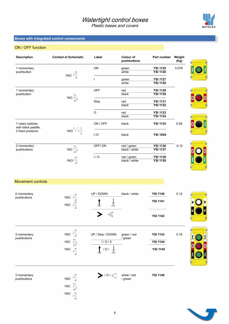
Description Contact et Schematic Label Colour of Part number Weight pushbuttons (Kg)
1 momentary ON green YSI 1125 0.076pushbutton white YSI 1126 1NO I green YSI 1127 white YSI 1128 1 momentary OFF red YSI 1129pushbutton black YSI 1130 1NC Stop red YSI 1131 black YSI 1132
O red YSI 1133 black YSI 1134
1 rotary switche ON / OFF black YSI 1135 0.08with black paddle,2 fi xed positions 1NO I /O black YSI 1854
2 momentary OFF/ ON red / green YSI 1136 0.12pushbuttons 1NC black / white YSI 1137
I / O red / green YSI 1138 1NO black / white YSI 1139
ON / OFF function
2 momentary UP / DOWN black / white YSI 1140 0.12pushbuttons 1NO YSI 1141 1NO
YSI 1142
3 momentary 1NO UP / Stop / DOWN green / red YSI 1143 0.16pushbuttons / green 1NC I / O / II YSI 1144
1NO / O / YSI 1145
3 momentary / O / white / red YSI 1146pushbuttons 1NO / green
1NC
1NO
Watertight control boxesPlastic bases and covers
Boxes with integrated control components
Movement controls
13
14
21
22
10 1
2
21
22
13
14
13
1413
14
13
14
13
14
21
22
13
14
13
14
21
22

AR
RE
T
MA
RC
HE
10 1
2
13
14
21
22
13
14
21
22
21
22 13
14
22
21
12
11
21
22
21
22
21
22
7
Description Contact & Schematic Label Colour of Part number Weight pushbuttons (Kg)
1 momentary ON green YSI 1147 0.14pushbutton 1NO white YSI 1148Chrome metal fl ange I green YSI 1149 white YSI 1150 1 momentary OFF red YSI 1151pushbutton black YSI 1152Chrome metal fl ange 1NC Stop red YSI 1153 black YSI 1154
O red YSI 1155 black YSI 1156
1 rotary switche ON / OFF black YSI 1157 0.16with black paddle, 1NO2 fi xed positions I /O black YSI 1847Chrome metal fl ange
2 momentary ON / OFF red / green YSI 1160 0.25pushbuttons 1NC black / white YSI 1161Chrome metal fl ange I / O red / green YSI 1845 1NO black / white YSI 1846
Stop function
1 latch mushroom 1NC 1NO None red YSI 1162pushbutton, ø40Released using No.620 keyChrome metal fl ange
2NC None red YSI 1163
1 push-pull mushroom 1NC None red YSI 1158 0.16pushbutton, ø40
1 push-pull mushroom 1NC None red YSI 1159 0.23pushbutton, ø70
1 latch mushroom 1NC None red YSI 1346pushbutton, ø30Rotate 1/4 turn to release
ON / OFF function
Watertight control boxesPlastic bases and covers
Boxes fi tted with Ø 22 control components
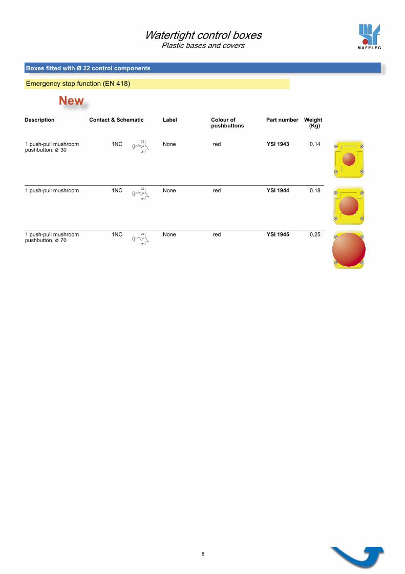
1 push-pull mushroom 1NC None red YSI 1943 0.14pushbutton, ø 30
1 push-pull mushroom 1NC None red YSI 1944 0.18
1 push-pull mushroom 1NC None red YSI 1945 0.25pushbutton, ø 70
21
22
21
22
21
22
New
8
Watertight control boxesPlastic bases and covers
Boxes fi tted with Ø 22 control components
Emergency stop function (EN 418)
Description Contact & Schematic Label Colour of Part number Weight pushbuttons (Kg)

STOP
STOP
13
14
13
14
13
14
13
14
13
14
13
14
21
22
21
22
x1
x2
13
14
21
22
21
22 13
14
21
2213
14
13
14
21
22
13
14
21
22
21
22
9
1 red latch mushroom 1NC 1NO ON / OFF red / green YSI 1172 0.33pushbutton, ø40, black / white YSI 1173Released by No. 620 key
2 momentarypushbuttons 1NC I / O red / green YSI 1843 black / white YSI 1844
1NO
1 red latch mushroom Stop / / white / black YSI 1249 0.25pushbutton, ø30,Released by turning 1/4 turn 1NCOverlapping contacts
1NC 1NO2 interlockedpushbuttons 1NC 1NO
ON / OFF function and signalling
Stop / OFF / ON function
Description Contact & Schematic Label Colour of Part number Weight pushbuttons (Kg)
2 momentary UP / DOWN black / white YSI 1164 0.25pushbuttons 1NOChrome metal fl ange
1NO YSI 1165
YSI 1166
3 momentary 1NO UP / Stop / DOWN green / red YSI 1167 0.36pushbuttons / greenChrome metal fl ange 1NC / O / YSI 1168
1NO
3 momentary white / red YSI 1169pushbuttons 1NO / O / / greenChrome metal fl ange
1NC
1NO
Watertight control boxesPlastic bases and covers
Boxes fi tted with Ø 22 control components
1 red pilot light ON / OFF red / green YSI 1170 0.2110X28 Ba9S bulb, max. 3W black / white YSI 1171power supply : 130V/50Hz.Chrome metal fl ange I / O red / green YSI 1841 1NC black / white YSI 1842
2 momentary pushbuttons 1NO
Movement control
Control boxes fi tted with 2 integrated control components + 1 Ø 22 control component

62 mm46 mm
54,5 mm
35 mm
A
30 m
m
16
mm
45 mm
B
Ø 4,5 mm
79 67 110 98 141 129
172 160
A B
5
9
2
5
10
1
3
4
6
7
8
5
5
10
Dimensions in mm
Distances between attachment holes for mounting on the support
Dimensions Cutouts
BTH CI (with integrated fl anges)for 1 to 4 integrated control components
BTH SC (without fl anges)for 1 to 4 control components, ø22
BTH 1 CIBTH 2 CIBTH 3 CIBTH 4 CI
BTH 1 SCBTH 2 SCBTH 3 SCBTH 4 SC
Combination BTH for 1 to 3 integrated components + 1 control component, ø 22 at one end
BTH 2 mixte BTH 3 mixte BTH 4 mixte
0.050.070.090.11
Description Part number Weight kg
0.050.070.090.11
0.070.090.11
3 - Recess for customer's logo4 - Recess for function labels5 - Knockoutsfor sealing gland (PG13)
6 - Holes, ø22SC versions (without fl anges) orCombination versions7 - FlangesCI versions (with integrated fl anges) orCombination versions
8 - 4 M3 screws9 - Gasket10- Hook(optional)
1 - Base2 - Cover
Watertight control boxesPlastic bases and covers
Empty boxes

2
4
5
7
9
8
STOP
STOP
3
5
6
1
4
11
Soft-touch pushbuttons
1- Head for soft-touch pushbuttons2- Electrical stack and screws (max. 1 tier) 1 speed : 1 - 2 or 3 contacts 2 speeds : 2 or 3 contacts
Rotary selector ON/OFF switches and inverters3- Head4- Electrical stack (max. 1 tier) with stable positions or automatic return
Interlock and screws (for 1-speed tier)Prevent two adjacent pushbuttonsfrom being activated simultaneously.
Specifi c control components for BTH CI and Combination BTH
3 4Assembly items for soft-touch pushbuttons - HeadsDescription Insert colour Part number
blackredyellowlight bluegreengreywhite
MAI 869 A00MAI 869 A20MAI 869 A40MAI 869 A60MAI 869 A50MAI 869 A80MAI 869 A90
(special for very low temperatures, contact us)
4 - Control components,ø 22 mm 5 - Integrated control components6 - Polycarbonate, adhesive labels on either side of the base.Standard or customised pictograms (contact us) 7 - Hook (optional)
3 - Sealing gland (P.E) StandardPG 13 with support clamps (pendant boxes) PG 13 without support clamps (fi xed boxes) On requestPG 13 spiral cable-guide, with support Material : POLYAMIDEStandards : NFC 63 021 and NFC 68 311
Soft-touch pushbutton head
Tighteningcapacity
Refer to control components in catalogue A6 and E1(A6: non-illuminated pushbuttons - Latch mushroom pushbuttons - selector switches - E1: Pilot lights )
ø 22 control components for BTH SC and Combination BTH
Max. 1 tier, with 1 or 2 contacts
1 2
1 - Base2 - Cover
Standard labels
BTH labels (3 components) PAI 210 A 005PAI 210 A 008PAI 210 A 016
Description Part number
BTH labels (2 components) PAI 209 A 001PAI 209 A 003
BTH labels (1 component) PAI 208 A 002PAI 208 A 003PAI 208 A 004PAI 208 A 005PAI 208 A 009
2
Watertight control boxesPlastic bases and covers
Complete control boxes
1
8 - 13 mm IP 6610 - 12 mm IP 66
6 - 12 mm IP 66

12
Description Contact Part number
Electrical stack 1 speedConstituent parts :-Contact block-attachment parts (screw and clamp plate)
YSI 1114
YSI 1115
YSI 1116
YSI 1117
YSI 1118
YSI 1119
Interlock for two pushbuttonswith 1 electrical tier and 1 speedCan be used on :BTH 2,3 and 4 CI (integrated fl anges)BTH 3 and 4 mixteConstituent parts :-Mechanism-Attachment parts
YSI 1122
YSI 1120
YSI 1121
2 speeds
Description Positions Colour Part number
1NO
1NC
1NO 1NC
2NO
2NC
2NO EB(single push with early-break contact)
1NO + 1NO(double push)
1NO + 1NO EB(double push withearly-break contact)
Assembly items for rotary selectors
Watertight control boxes Plastic bases and covers
Assembly items for soft-touch pushbuttons
For BTH CI (with integrated fl anges):Rotary switche headComposition : black YSI 1123-Paddle (Contact us-Adapter for other colours)-Gasket-Screw
For BTH SC (without fl anges):Rotary switche headComposition : black LSND BTH- Paddle (Contact us- Chrome metal fl ange for other colours)- Adapter - Screw
Accessory for BTH
Description Colour Part number
Holster for box Black MAI1083A8
1 2
1 2

0 1
0 1
12
43
0 1
8101
8102 81
01 b
is
8102
bis
0 1
0 1
12
43
0 1
RA
8101
8102 81
01 b
is
8102
bis
1 2
1 2
12
43 8951
1 2
1 2
12
43
RA
8951
1 2
1 0 2
12
43
0
8901
1 2
1 0 2
12
43
0RARA
8901
1 2
1 0 2
12
43
0RA
8901
0
1
1 2
1 0 2
12
43
0RA
8901
1
2
0
21
13
One-pole ON/OFF switch BTH 8101 BTH 8101 bis
BTH 8102 BTH 8102 bis
BTH 8101/2
2 stable positions
One-pole ON/OFF switch BTH 8101 RA BTH 8101 RA bis
Two-pole ON/OFF switch BTH 8102 RA BTH 8102 RA bis
2 positions, 1 with automatic return from right to left
One-pole inverter BTH 8951
BTH 8951/2
2 stable positions
One-pole inverter BTH 8951 RA
2 positions, 1 with automatic return from right to left
Standardised schematic Function Part number
One-pole inverter BTH 8901
BTH 8901/4
3 positions, OFF in the centre
One-pole inverter BTH 8901 RA
3 positions, 2 with automatic return to centre
One-pole inverter BTH 8901 RA 1-0
3 positions, 1 with automatic return from left to centre
3 positions, 1 with automatic return from right to centre
One-pole inverter BTH 8901 RA 2-0
Electrical subassembly for BTH CI or Combination BTH Constituent parts : - Contact block - 4 or 8 positions mechanism - Attachment parts (screw and clamp plate)
positions at 90°
Two-pole ON/OFF switch
positions at 90°
positions at 90°
Watertight control boxesPlastic bases and covers
Assembly items for rotary switches

14
Choose the ø 22 components (From our A6 and E1 catalogues) Standard pictograms (see list for P/N)
123
4
position Left RightElectrical stack P/N + Head P/N
Conpose your own product
Photocopy this page and complete the charts
Check the boxes corresponding to the options you want.
position 1
Cover Base Select sealing gland Attachment parts
Hook at A or B 1 hole (ø 21) for sealing gland (PG 13)
Leave blank if you do not want Leave blank if you do not want any hook any hole
with support clamp PG 13 A B C D
with cable-guide (without support clamps)
Interlock Choose de components Standard pictograms (see list for P/N)
BTH without fl anges
A
B
C
D
Cover(inside view)
Base
BTH
1
BTH
2
BTH
3
BTH
4
BTH with integrate fl anges
other (specify)
Combination BTH
Body / Electrical stack P/N + Head P/N
1
2
34
position
Boxes without fl anges
Contact us for customised pictograms and company logos.
Standard Stailess steel
Watertight control boxesBTH spécifi ques
Defi nition chartDefi nition chart
Boxes with integrated fl anges or Combination boxes
without support clamp
Left Right
38,5
45
30,5
30,5
Ø 22,5
==
38,5
45
30
,53
0,5
Ø 22,5
==
L
C
d90
53
H
h
d
15
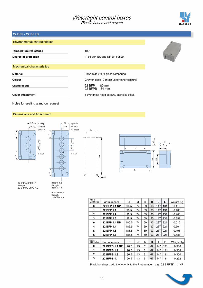
Holes for sealing gland on request
74
ø 5.5
specify centred or offset
22 BFP or BFPB 1.1 through 22 BFP OU BFPB 1.3
22 BFP 1.4through 22 BFP 1.6
or 22 BFPB 1.1through 22 BFPB 1.3
specify centred or offset
Black housings : add the letter N to the Part number, e.g.: 22 BFP"N" 1.1 NP
Part numbers c d h H L E Weight Kg22 BFPB 1.1 NP 96.5 43 51 67 147 131 0.31622 BFPB 1.1 96.5 43 51 67 147 131 0.30822 BFPB 1.2 96.5 43 51 67 147 131 0.30022 BFPB 1. 96.5 43 51 67 147 131 0.292
Part numbers c d h H L E Weight Kg22 BFP 1.1 NP 96.5 74 69 93 147 131 0.41622 BFP 1.1 96.5 74 69 93 147 131 0.40822 BFP 1.2 96.5 74 69 93 147 131 0.40022 BFP 1.3 96.5 74 69 93 147 131 0.39222 BFP 1.4 NP 186.5 74 69 93 237 221 0.51222 BFP 1.4 186.5 74 69 93 237 221 0.50422 BFP 1.5 186.5 74 69 93 237 221 0.49622 BFP 1.6 186.5 74 69 93 237 221 0.488
Nbr of ø22 holes
01230456
Nbr of ø22 holes
0123
E
Watertight control boxesPlastic bases and covers
22 BFP - 22 BFPB
Environmental characteristics
Material Polyamide / fi bre-glass compound
Colour Grey or black (Contact us for other colours)
Useful depth 22 BFP - 80 mm 22 BFPB - 54 mm
Cover attachment 4 cylindrical-head screws, stainless steel.
Temperature resistance 100°
Degree of protection IP 66 per IEC and NF EN 60529
Mechanical characteristics
Dimensions and Attachment

A
A
B B
1
2
3
4
5
6
1
2
3
16
Tighteningcapacity
Select sealing gland
PG 9
PG 11
PG 13
PG 16
Other (specify)
OutputsA B
Housing P/N Choose your Ø 22 items Choose your labels Type of screws
123456
position
Holes
Centred Offset
Photocopy this page and complete the charts
Check the boxes corresponding to the options you want.
6 - 10 mm
8 - 13 mm
10 - 15 mm
Nbr of glands
BFP only
1 2
5 - 8 mm
(refer to catalogue A6 and E1 for P/Ns)
Watertight control boxesPlastic bases and covers
22 BFP - 22 BFPB
Composing your own control box
Std. St. steel

START
STOP
6
5
4
3
1
2
7
56.5
20
17
1- Housing
2 - Sealing glandP/N Tightening capacity
PG 11 7-10 mmPG 13 10-12 mmPG 16 12-14 mmPG 21 14-19 mm
Material : nickel-plate brassSealing : IP 66Standards : NFC 63021 and NFC 68312
Contact us for the other sealing gland typee.g.: Plastic gland with cable guide
3 - Customer logo
4 - LC 22 control componentsRefer to catalogue A6 and E1 for the P/Ns for Ø22 components
5 - Polycarbonate labels, adhesive, on the either side of the front panel.Standard or customised pictograms(contact us)
6 - Guard
7 - Blanking plug
Storage temperature
Operating temperature
Degree of protection
Resistance to chemicals
Fire resistance
- 40°C to +70°C
- 25°C to +70°C
IP 667 per IEC & NF EN 60 529
Highly resistance to acids, chemical bases and to petroleum products.
HB per UL 94
Mechanical characteristics
Material
Gasket
Cable entry
Attachment for support
Base / cover attachment
Weight ( kg )
Polyamide / fi bre-glass compound, coloured in the moulding. Standard colour : black, contact us for other colours. 4, 5, 6, 8, 10, or 12 holes, ø 22 mm
Foam, cord, ø 3 mm
Sealing gland
2 possibilities : four H M5 srews and nuts or four C M5 screws and tapped hexagonal shims Tightening torque not more than 0.5 m. Kg
Captive screws, hex. socket heads (CHC), ARCOR treated steel or cylindrical slotted head (CS). Standard : stainless steel Option: steel. Max. tightening torque : 2.5 Nm
See dimensions chart
Environmental characteristics
Complete boxes
When selecting your components, allow for the useful depth between the base and caver (56.5 mm)
Watertight control boxesPlastic bases and covers
BBE

6
5
4
3
1
2
7
D
857.
564 1882
80100
40
ABC
5050
50=
=
= =
18
2 alternatives for attachment :
4 tapped M5 hexagonal shimsdichromate galvanised steel, Mounting: Complete box, mounting accessible from outside the box.
four HM5 screwsMounting : rear cover attached fi rst, then the complete front panel (base)
(tightening torque: 0.5m. kg )
Dimensions Attachment
Housing A B C D Weight (Kg)
BBE 4 270 230 190 257.5 0.465BBE 5 320 280 240 307.5 0.535BBE 6 370 330 290 358 0.615BBE 8 470 430 390 459 0.740BBE 10 570 530 490 560 0.810BBE 12 670 630 590 661 0.960
BBE 4 BBE 5 BBE 6 BBE 8 BBE 10 BBE 12
Empty boxes
Watertight control boxesPlastic bases and covers
BBE
- Recess for Labels
- Customer logos
- Captive attachment parts
- Front panel : Base
- Holes for sealing gland, to order
- Gasket
- Rear Cover
1 2
1
2

START STOP STOP
MANU. AUTO.
AUTOMATIC
CYCLE
AUTOMATIC
CYCLE STARTCYCLE
RETRACT
0 1
+
1 2 3 4 5 6 7 8 9
10 11 12 13 14 15 16 17 18
19 20 21 22 23 24 25 26 27
28 29 30 31 32 33 34 35 36
19
Select sealing gland
PG 11
PG 13
PG 16
PG 21
Other (specify)
Housing type Choose your Ø 22 items Accessories Standard pictograms (refer to catalogue A6 and E1 for P/N) (P/N: list on request)
123456789101112
position Guard PlugP/N for body / electrical stack + Head P/N Left Right
Contact us for Company logos and customised pictograms
OutputsA B
Photocopy this page and complete the charts (Check the boxes corresponding to the options you want)
B
Guards are only available for ø 40 pushbuttons
BBE
4 BBE
5 BBE
6BBE
8BBE
10BBE
12
Std. St. steelType of screws
position 1
Standard labels
A
Watertight control boxesPlastic bases and covers
BBE
Composing your own Box with recessed controls
7
12
0
159
21
0
117
146
190
25
0
6 X M4x8
78
62
20
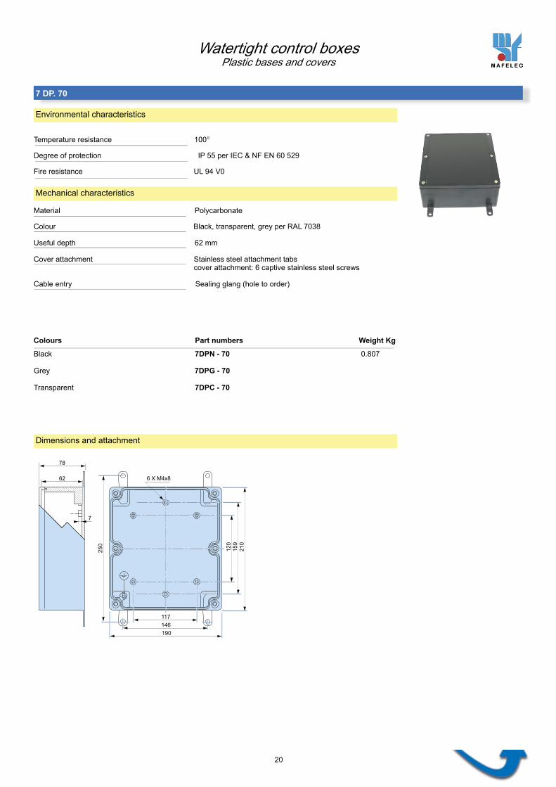
Colours Part numbers Weight Kg
Black 7DPN - 70 0.807
Grey 7DPG - 70
Transparent 7DPC - 70
Watertight control boxesPlastic bases and covers
7 DP. 70
Environmental characteristics
Temperature resistance 100°
Degree of protection IP 55 per IEC & NF EN 60 529
Fire resistance UL 94 V0
Material Polycarbonate
Colour Black, transparent, grey per RAL 7038
Useful depth 62 mm
Cover attachment Stainless steel attachment tabs cover attachment: 6 captive stainless steel screws
Cable entry Sealing glang (hole to order)
Mechanical characteristics
Dimensions and attachment

73 76
APe
rçag
es Ø
22,5
au
pas
de 3
0,5m
m
21
Housing delivered with threaded hole for PE 13 sealing gland.
Part numbers A B Weight Kg22 BF 1.1 NP 120 85 1 0.56022 BF 1.1 120 85 1 0.54022 BF 1.2 120 85 1 0.52022 BF 1.3 NP 180 145 1 0.74022 BF 1.3 180 145 1 0.72022 BF 1.4 180 145 1 0.70022 BF 1.5 NP 270 235 2 0.94522 BF 1.5 270 235 2 0.92522 BF 1.6 270 235 2 0.90522 BF 1.7 270 235 2 0.885
Nbr of glands per side
Nbr of ø22holes
0120340567
ø 6,5
B
Watertight control boxesLight Alloy bases and covers
22BF.
Environmental characteristics
Degree of protection IP 55 IP 55 per IEC & NF EN 60 529
Material Aluminium alloy
Colour Blue (Contact us for other colours)
Useful depth 65 mm
Cover attachment 4 cylindrical-head screws
Mechanical characteristics
Dimensions and attachment
Hol
es: Ø
22.5
at a
pitc
h of
30.
5 m
m

212
C
197
137 x 64 122 x 64Zones
presse étoupes
149
A
BD Emplacements
étiquettes
352
C
212
277 x 64 137 x 64Zones presse étoupes
149
A
BD Emplacements étiquettes
22
Part numbers Weight Kg
3.325
Dimensions and attachment Part numbers
Part numbers Weight Kg
I 6 D 145 CHPC (Hinge on short side) 1.750 1.750 I 6 D 145 CHGC (Hinge on long side)
I 12 D 145 CHPC (Hinge on short side) I 12 D 145 CHGC (Hinge on long side) 3.325
Watertight control boxesLight alloy bases and covers
I 6 D 145 - I 12 D 145
Environmental characteristics
Degree of protection IP 55 per IEC & NF EN 60529
Material Sheet steel
Colour Bare steel (not painted)
Useful depth 145 mm
Cover attachment 2 hinges 4 cylindrical-head screws
Mechanical characteristics
Dimensions and attachment Part numbers
Sealing gland zone
Locations for labels
Locations for labels
Sealing gland zone