Embed Size (px)
Citation preview

OM-05169October 18, 2000Rev. J 11‐10‐17
GORMAN‐RUPP PUMPSwww.grpumps.com
�2000 Gorman‐Rupp Pumps Printed in U.S.A.
INSTALLATION AND
OPERATION MANUALWITH PARTS LISTS
SINGLE PHASE CONTROL BOXES
MODELS
27511-101 27511-10527511-102 27511-10627511-103 27511-10727511-104

TABLE OF CONTENTS
i
INTRODUCTION PAGE I - 1. . . . . . . . . . . . . . . . . . . . . . . . . . . . . . . . . . . . . . . . . . . . . . . . . . . . . .WARRANTY INFORMATION PAGE I - 1. . . . . . . . . . . . . . . . . . . . . . . . . . . . . . . . . . . . . . . . . . . . . . . . . . . . . . . .
SAFETY - SECTION A PAGE A - 1. . . . . . . . . . . . . . . . . . . . . . . . . . . . . . . . . . . . . . . . . . . . . . .
INSTALLATION - SECTION B PAGE B - 1. . . . . . . . . . . . . . . . . . . . . . . . . . . . . . . . . . . . . . . .GENERAL INFORMATION PAGE B - 1. . . . . . . . . . . . . . . . . . . . . . . . . . . . . . . . . . . . . . . . . . . . . . . . . . . . . . . . .
PREINSTALLATION INSPECTION PAGE B - 1. . . . . . . . . . . . . . . . . . . . . . . . . . . . . . . . . . . . . . . . . . . . . . . . . .
CONTROL BOX INSTALLATION PAGE B - 1. . . . . . . . . . . . . . . . . . . . . . . . . . . . . . . . . . . . . . . . . . . . . . . . . . . .
Enclosure PAGE B - 1. . . . . . . . . . . . . . . . . . . . . . . . . . . . . . . . . . . . . . . . . . . . . . . . . . . . . . . . . . . . . . . . . . . . .
27511-101, 102, 103, 104, 106 And 107 CONTROL BOX DIMENSIONS PAGE B - 1. . . . . . . . . . . . . . . .
27511-101, 102, 103, 104, 106 And 107 CONTROL BOX PARTS LIST PAGE B - 3. . . . . . . . . . . . . . . . . .
27511-105 CONTROL BOX DIMENSIONS PAGE B - 5. . . . . . . . . . . . . . . . . . . . . . . . . . . . . . . . . . . . . . . . . .
27511-105 CONTROL BOX PARTS LIST PAGE B - 5. . . . . . . . . . . . . . . . . . . . . . . . . . . . . . . . . . . . . . . . . . . .
ELECTRICAL CONNECTIONS PAGE B - 6. . . . . . . . . . . . . . . . . . . . . . . . . . . . . . . . . . . . . . . . . . . . . . . . . . . . .
Grounding Methods PAGE B - 6. . . . . . . . . . . . . . . . . . . . . . . . . . . . . . . . . . . . . . . . . . . . . . . . . . . . . . . . . . . .
Field Wiring Connections (Incoming Power) PAGE B - 7. . . . . . . . . . . . . . . . . . . . . . . . . . . . . . . . . . . . . . .
Pump Motor Voltage Limits PAGE B - 7. . . . . . . . . . . . . . . . . . . . . . . . . . . . . . . . . . . . . . . . . . . . . . . . . . . . . .
Power Cable Connections PAGE B - 7. . . . . . . . . . . . . . . . . . . . . . . . . . . . . . . . . . . . . . . . . . . . . . . . . . . . . . .
Control Box Specifications PAGE B - 7. . . . . . . . . . . . . . . . . . . . . . . . . . . . . . . . . . . . . . . . . . . . . . . . . . . . . .
27511-101, 102, 103, 104, 106 And 107 Control Box Pictorial Wiring Diagram PAGE B - 8. . . . . . . .
27511-101, 102, 103, 104, 106 And 107 Elementary Wiring Diagram PAGE B - 9. . . . . . . . . . . . . . . . .
27511-105 Control Box Pictorial Wiring Diagram PAGE B - 10. . . . . . . . . . . . . . . . . . . . . . . . . . . . . . . . .
27511-105 Elementary Wiring Diagram PAGE B - 11. . . . . . . . . . . . . . . . . . . . . . . . . . . . . . . . . . . . . . . . .
OPERATION - SECTION C PAGE C - 1. . . . . . . . . . . . . . . . . . . . . . . . . . . . . . . . . . . . . . . . . .CONTROL BOX FUNCTION PAGE C - 1. . . . . . . . . . . . . . . . . . . . . . . . . . . . . . . . . . . . . . . . . . . . . . . . . . . . . . .
Component Function PAGE C - 1. . . . . . . . . . . . . . . . . . . . . . . . . . . . . . . . . . . . . . . . . . . . . . . . . . . . . . . . . . .
TROUBLESHOOTING - SECTION D PAGE D - 1. . . . . . . . . . . . . . . . . . . . . . . . . . . . . . . . . .TROUBLESHOOTING CHART PAGE D - 1. . . . . . . . . . . . . . . . . . . . . . . . . . . . . . . . . . . . . . . . . . . . . . . . . . .
ELECTRICAL TESTING PAGE D - 2. . . . . . . . . . . . . . . . . . . . . . . . . . . . . . . . . . . . . . . . . . . . . . . . . . . . . . . . . . .
Test Equipment PAGE D - 2. . . . . . . . . . . . . . . . . . . . . . . . . . . . . . . . . . . . . . . . . . . . . . . . . . . . . . . . . . . . . . . .
Voltage Imbalance PAGE D - 2. . . . . . . . . . . . . . . . . . . . . . . . . . . . . . . . . . . . . . . . . . . . . . . . . . . . . . . . . . . . .
Capacitors PAGE D - 2. . . . . . . . . . . . . . . . . . . . . . . . . . . . . . . . . . . . . . . . . . . . . . . . . . . . . . . . . . . . . . . . . . . .
Start Relay PAGE D - 2. . . . . . . . . . . . . . . . . . . . . . . . . . . . . . . . . . . . . . . . . . . . . . . . . . . . . . . . . . . . . . . . . . . .

OM-05169CONTROL BOXES
PAGE I - 1INTRODUCTION
INTRODUCTION
Read this manual carefully to learn how to safely
install and operate your control box. Failure to do
so could result in personal injury or damage to the
control box or the pump.
This manual does not include maintenance in
structions. Have a qualified electrician perform all
maintenance. Be sure to follow all safety precau
tions as outlined by the National Electric Code and
all local codes.
These control boxes are Nema Type 3R rainproof
enclosures with padlockable front covers. The en
closures are not designed to be watertight, and
should not be submerged. They are designed for
use with 110, 115, 220 and 230 volt, single phase
Gorman‐Rupp submersible pumps. The integral
electric motor of the submersible pump must be
operated through the control box. The control box
is not explosion‐proof and should not be operated
in a hazardous atmosphere.
Because pump installations are seldom identical,
this manual cannot possibly provide detailed in
structions and precautions for every aspect of
each specific application. Therefore, it is the re
sponsibility of the owner/installer of the pump to
ensure that applications not addressed in this
manual are performed only after establishing that
neither operator safety nor pump integrity are com
promised by the installation. Pumps and related
equipment must be installed and operated ac
cording to all national, local and industry stan
dards.
If there are any questions regarding the control box
which are not covered in this manual or in other lit
erature accompanying the unit, please contact
your Gorman‐Rupp distributor or the Gorman‐
Rupp Company:
The Gorman‐Rupp Company
P.O. Box 1217
Mansfield, Ohio 44901-1217
or:
Gorman‐Rupp of Canada Limited
70 Burwell Road
St. Thomas, Ontario N5P 3R7
RECORD CONTROL BOX NUMBER
Please record the control box number, voltage,
phase, and pump model in the spaces provided
below. Your Gorman‐Rupp distributor needs this
information when you require parts or service.
Control Box:
Voltage:
Phase:
Pump Model:
WARRANTY INFORMATION
The warranty provided with your control box is part
of Gorman‐Rupp's support program for customers
who operate and maintain their equipment as de
scribed in this and the other accompanying litera
ture. Please note that should the equipment be
abused or modified to change its performance be
yond the original factory specifications, the war
ranty will become void and any claim will be de
nied.
The following are used to alert personnel to proce
dures which require special attention, to those
which could damage equipment, and to those
which could be dangerous to personnel:
Immediate hazards which WILL result insevere personal injury or death. Theseinstructions describe the procedure required and the injury which will resultfrom failure to follow the procedure.
Hazards or unsafe practices whichCOULD result in severe personal injuryor death. These instructions describethe procedure required and the injurywhich could result from failure to followthe procedure.

OM-05169 CONTROL BOXES
PAGE I - 2 INTRODUCTION
Hazards or unsafe practices which COULDresult in minor personal injury or product orproperty damage. These instructions describe the requirements and the possible
damage which could result from failure tofollow the procedure.
NOTEInstructions to aid in installation, operation, and
maintenance or which clarify a procedure.

CONTROL BOXES OM-05169
SAFETY PAGE A - 1
SAFETY - SECTION A
The following information appliesthroughout this manual to Gorman‐Rupp Control Boxes.
Because pump installations are seldomidentical, this manual cannot possiblyprovide detailed instructions and precautions for each specific application.Therefore, it is the owner/installer's responsibility to ensure that applicationsnot addressed in this manual are performed only after establishing that neither operator safety nor pump integrityare compromised by the installation.
Before attempting to install, operate, orwire this control box, familiarize yourself with this manual, and with all otherliterature shipped with the control box.Unfamiliarity with all aspects of controloperation covered in this manual couldlead to destruction of equipment, injury,or death to personnel.
Before connecting any cable to the control box, be sure to ground the controlbox. See Section B for suggestedgrounding methods.
The control box provides overload protection and power control. Do not connect the pump motor directly to the incoming power lines. If the power circuitbreaker or overload relay is tripped dur
ing operation, correct the problem before resetting or replacing.
The electrical power used to operatethis control box is high enough to causeinjury or death. Obtain the services of aqualified electrician to make all electrical connections. Make certain that theenclosure is properly grounded; neveruse gas pipe as an electrical ground. Besure that the incoming power matchesthe voltage and phase of the control before connecting the power source. Donot make electrical connections if thevoltage is not within the limits. If theoverload unit is tripped during operation, correct the problem before restarting.
The electrical power used to operatethis control box is high enough to causeinjury or death. Make certain that thecontrol handle on the control box is inthe OFF position and locked out, or thatthe power supply to the control box hasbeen otherwise cut off and locked out,before attempting to open or service thecontrol box. Tag electrical circuits toprevent accidental start‐up.
Obtain the services of a qualified electrician to troubleshoot, test and/or service the electrical components of thiscontrol box.

OM-05169 CONTROL BOXES
PAGE A - 2 SAFETY
Do not attempt to repair individual components of the control box. Any component which fails should be replaced.
CONTROL BOXES OM-05169
PAGE B - 1INSTALLATION
INSTALLATION - SECTION B
GENERAL INFORMATION
Review all SAFETY information in Section A.
This section is intended only to summarize recom
mended installation practices for the control box. If
there are any questions concerning your specific
application, contact your Gorman‐Rupp distributor
or the Gorman‐Rupp Company.
PREINSTALLATION INSPECTION
The control box was inspected before shipment
from the factory. Before installation, inspect the
control for damage which may have occurred dur
ing shipment. Check as follows:
a. Inspect the control box for cracks, dents, and
other obvious damage.
b. Check that all control box components are se
curely attached to their mounting surfaces,
and that the electrical connections are tight
and free of corrosion.
c. Compare the amperes, phase, voltage and
hertz indicated on the pump motor nameplate
to the ratings indicated for the control box.
d. Carefully read all tags, decals, and markings
on the control box.
If anything appears to be abnormal, contact your
Gorman‐Rupp distributor or the factory to deter
mine the repair policy. Do not put the control box
into service until appropriate action has been
taken.
CONTROL BOX INSTALLATION
The control box furnished with thepump is designed to operate the pump.The control box provides overload protection and power control. Do not connect the pump motor directly to the incoming power lines.
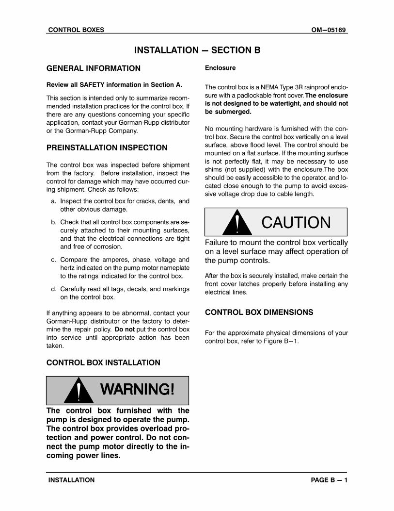
Enclosure
The control box is a NEMA Type 3R rainproof enclo
sure with a padlockable front cover. The enclosure
is not designed to be watertight, and should not
be submerged.
No mounting hardware is furnished with the con
trol box. Secure the control box vertically on a level
surface, above flood level. The control should be
mounted on a flat surface. If the mounting surface
is not perfectly flat, it may be necessary to use
shims (not supplied) with the enclosure.The box
should be easily accessible to the operator, and lo
cated close enough to the pump to avoid exces
sive voltage drop due to cable length.
Failure to mount the control box verticallyon a level surface may affect operation ofthe pump controls.
After the box is securely installed, make certain the
front cover latches properly before installing any
electrical lines.
CONTROL BOX DIMENSIONS
For the approximate physical dimensions of your
control box, refer to Figure B-1.
OM-05169 CONTROL BOXES
PAGE B - 2 INSTALLATION
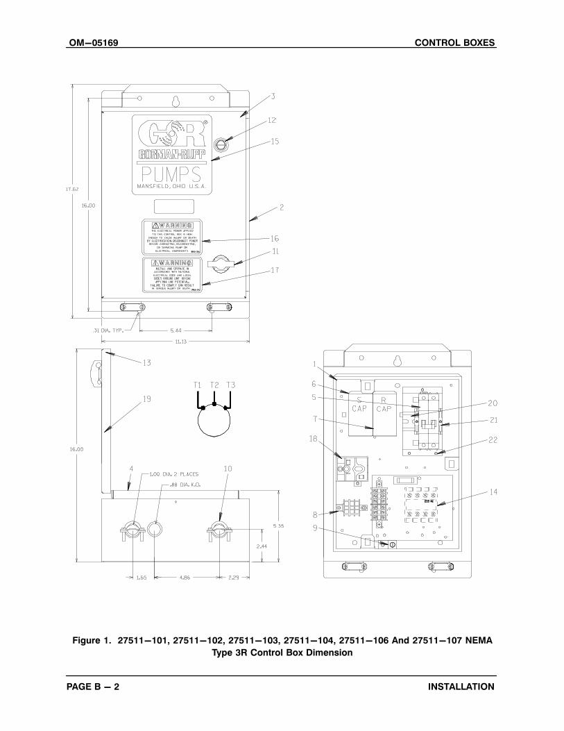
Figure 1. 27511-101, 27511-102, 27511-103, 27511-104, 27511-106 And 27511-107 NEMA
Type 3R Control Box Dimension
CONTROL BOXES OM-05169
PAGE B - 3INSTALLATION
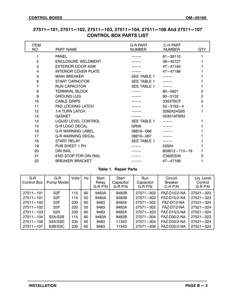
27511-101, 27511-102, 27511-103, 27511-104, 27511-106 And 27511-107
CONTROL BOX PARTS LIST
ITEM NO. PART NAME
G‐R PART NUMBER QTY
C‐H PART NUMBER
1 PANEL --- 81-26110 1
2 ENCLOSURE WELDMENT --- 39-45727 1
3 EXTERIOR DOOR ASM --- 47-47184 1
4 INTERIOR COVER PLATE --- 47-47186 1
5 MAIN BREAKER SEE TABLE 1 --- 1
6 START CAPACITOR SEE TABLE 1 --- 1
7 RUN CAPACITOR SEE TABLE 1 --- 1
8 TERMINAL BLOCK --- 80-5821 2
9 GROUND LUG --- 80-3132 2
10 CABLE GRIPS --- 3303TBCF 2
11 PAD LOCKING LATCH --- 52-3182-4 1
12 1/4 TURN LATCH --- 2092A24G05 1
13 GASKET --- 45301AFBR3
14 LIQUID LEVEL CONTROL SEE TABLE 1 --- 1
15 G‐R LOGO DECAL GR06 --- 1
16 G‐R WARNING LABEL 38816-066 --- 1
17 G‐R WARNING DECAL 38816-067 --- 1
18 START RELAY SEE TABLE 1 --- 1
19 PUB SHEET 1 PH --- 52924 1
20 DIN RAIL --- 800612-113-19 1
21 END STOP FOR DIN RAIL --- C383ES35 2
22 BREAKER BRACKET --- 47-47188 1
Table 1. Repair Parts
27511-101 S2F 115 60 9483A 9482B 27571-303 FAZ‐D15/2‐NA 27521-323
27511-101 S2F 110 50 9483A 9482B 27571-303 FAZ‐D15/2‐NA 27521-323
27511-102 S2F 230 60 9483 9482A 27571-302 FAZ‐D7/2‐NA 27521-324
27511-102 S2F 220 50 9483 9482A 27571-302 FAZ‐D7/2‐NA 27521-324
27511-103 S2A 230 60 9483 9482A 27571-323 FAZ‐D15/2‐NA 27521-324
27511-104 S2A/S2B 115 60 9483A 9482B 27571-304 FAZ‐D30/2‐NA 27521-323
27511-106 S3A/S3D 230 60 9483 11343 27571-304 FAZ‐D30/2‐NA 27521-324
27511-107 S3B/S3C 230 60 9483 11343 27571-306 FAZ‐D35/2‐NA 27521-324
G‐RControl Box
G‐RPump Model
Volts Hz StartRelay
G‐R P/N
StartCapacitorG‐R P/N
RunCapacitorG‐R P/N
CircuitBreakerC‐H P/N
Liq. LevelControlG‐R P/N

OM-05169 CONTROL BOXES
PAGE B - 4 INSTALLATION
Figure 2. 27511-105 NEMA Type 3R Control Box Dimension
CONTROL BOXES OM-05169
PAGE B - 5INSTALLATION
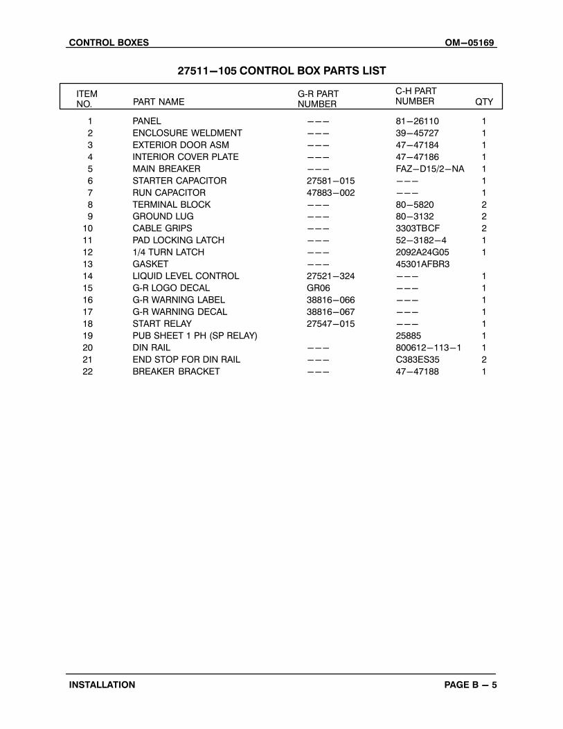
27511-105 CONTROL BOX PARTS LIST
ITEM NO. PART NAME
G‐R PART NUMBER QTY
C‐H PART NUMBER
1 PANEL --- 81-26110 1
2 ENCLOSURE WELDMENT --- 39-45727 1
3 EXTERIOR DOOR ASM --- 47-47184 1
4 INTERIOR COVER PLATE --- 47-47186 1
5 MAIN BREAKER --- FAZ-D15/2-NA 1
6 STARTER CAPACITOR 27581-015 --- 1
7 RUN CAPACITOR 47883-002 --- 1
8 TERMINAL BLOCK --- 80-5820 2
9 GROUND LUG --- 80-3132 2
10 CABLE GRIPS --- 3303TBCF 2
11 PAD LOCKING LATCH --- 52-3182-4 1
12 1/4 TURN LATCH --- 2092A24G05 1
13 GASKET --- 45301AFBR3
14 LIQUID LEVEL CONTROL 27521-324 --- 1
15 G‐R LOGO DECAL GR06 --- 1
16 G‐R WARNING LABEL 38816-066 --- 1
17 G‐R WARNING DECAL 38816-067 --- 1
18 START RELAY 27547-015 --- 1
19 PUB SHEET 1 PH (SP RELAY) 25885 1
20 DIN RAIL --- 800612-113-1 1
21 END STOP FOR DIN RAIL --- C383ES35 2
22 BREAKER BRACKET --- 47-47188 1
OM-05169 CONTROL BOXES
PAGE B - 6 INSTALLATION
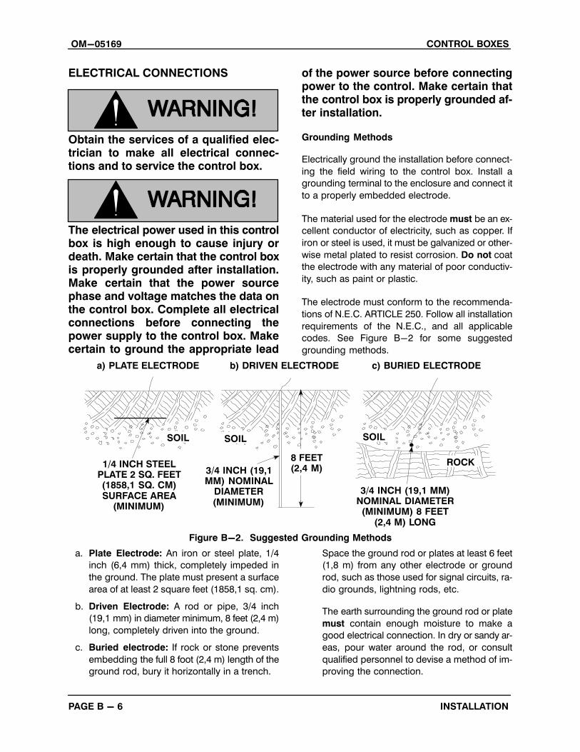
ELECTRICAL CONNECTIONS
Obtain the services of a qualified electrician to make all electrical connections and to service the control box.
The electrical power used in this controlbox is high enough to cause injury ordeath. Make certain that the control boxis properly grounded after installation.Make certain that the power sourcephase and voltage matches the data onthe control box. Complete all electricalconnections before connecting thepower supply to the control box. Makecertain to ground the appropriate lead
of the power source before connectingpower to the control. Make certain thatthe control box is properly grounded after installation.
Grounding Methods
Electrically ground the installation before connect
ing the field wiring to the control box. Install a
grounding terminal to the enclosure and connect it
to a properly embedded electrode.
The material used for the electrode must be an ex
cellent conductor of electricity, such as copper. If
iron or steel is used, it must be galvanized or other
wise metal plated to resist corrosion. Do not coat
the electrode with any material of poor conductiv
ity, such as paint or plastic.
The electrode must conform to the recommenda
tions of N.E.C. ARTICLE 250. Follow all installation
requirements of the N.E.C., and all applicable
codes. See Figure B-2 for some suggested
grounding methods.
ROCK8 FEET(2,4 M)3/4 INCH (19,1
MM) NOMINALDIAMETER(MINIMUM)
SOILSOILSOIL
1/4 INCH STEELPLATE 2 SQ. FEET(1858,1 SQ. CM)SURFACE AREA
(MINIMUM)
a) PLATE ELECTRODE b) DRIVEN ELECTRODE c) BURIED ELECTRODE
3/4 INCH (19,1 MM)NOMINAL DIAMETER(MINIMUM) 8 FEET
(2,4 M) LONG
Figure B-2. Suggested Grounding Methods
a. Plate Electrode: An iron or steel plate, 1/4
inch (6,4 mm) thick, completely impeded in
the ground. The plate must present a surface
area of at least 2 square feet (1858,1 sq. cm).
b. Driven Electrode: A rod or pipe, 3/4 inch
(19,1 mm) in diameter minimum, 8 feet (2,4 m)
long, completely driven into the ground.
c. Buried electrode: If rock or stone prevents
embedding the full 8 foot (2,4 m) length of the
ground rod, bury it horizontally in a trench.
Space the ground rod or plates at least 6 feet
(1,8 m) from any other electrode or ground
rod, such as those used for signal circuits, ra
dio grounds, lightning rods, etc.
The earth surrounding the ground rod or plate
must contain enough moisture to make a
good electrical connection. In dry or sandy ar
eas, pour water around the rod, or consult
qualified personnel to devise a method of im
proving the connection.

CONTROL BOXES OM-05169
PAGE B - 7INSTALLATION
Field Wiring Connections (Incoming Power)
The electrical power used to operatethis pump is high enough to cause injury or death. Obtain the services of a qualified electrician to make all electricalconnections. Make certain that thepump and enclosure are properlygrounded; never use gas pipe as anelectrical ground. Be sure that the incoming power matches the voltage andphase of the pump and control beforeconnecting the power source. Do notrun the pump if the voltage is not withinthe limits.
The control is designed to regulate the power sup
ply. The field wiring must be properly sized to en
sure an adequate voltage supply. The voltage
available at the pump motor must be within the in
dicated range.
Table 3. Pump Motor Voltage Limits
NominalVoltage
MinimumVoltage
MaximumVoltagePhase
200 1 190 210
115 1 110 120
230 1 220 240
220 (50 Hz) 1 209 230
If the voltage is not within the recommended limits,
obtain the services of a qualified electrician to de
termine the correct field wiring size and other de
tails to ensure an adequate voltage supply.
Make certain all connections are tight and that ca
ble entry points are rainproof. Support the cable
weight, if required, to prevent excessive strain on
cable clamps and cable.
NOTEAfter the power cables have been connected to the
control box, make certain the connection is water
proof.
Power Cable Connections
The electrical power used to operate thecontrol box is high enough to cause injury or death. Obtain the services of aqualified electrician to make all electrical connections. Make certain that incoming power to the control box is in theoff position and locked out, or that thepower supply to the control box hasbeen otherwise cut off and locked out,before connecting power or accessorycables.
When necessary to change or connect power
cables to the control box, make certain the incom
ing power is OFF and LOCKED OUT. Make certain
the control box is properly grounded and that the
electrical data on the control matches the pump
motor name plate data.
Connect the power cable to the control box as
shown in the wiring diagrams in this section. Use
conduit or cable clamps to secure the power and
accessory cables to the control box. Make certain
that all connections are tight and that cable entry
points are rainproof.
Control Box Specifications
Overload relays are provided to protect the pump
motor.
If burnout of the overload protection occurs, the complete overload protectionmust be replaced.
OM-05169 CONTROL BOXES
PAGE B - 8 INSTALLATION
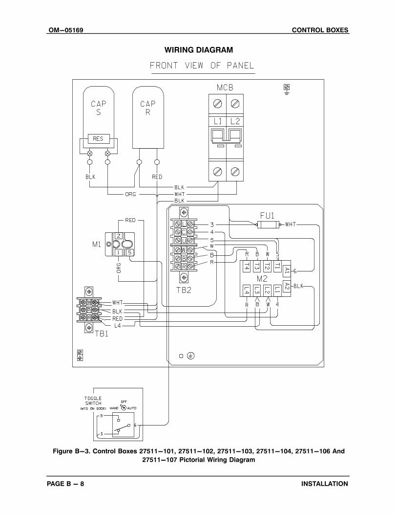
WIRING DIAGRAM
Figure B-3. Control Boxes 27511-101, 27511-102, 27511-103, 27511-104, 27511-106 And
27511-107 Pictorial Wiring Diagram
CONTROL BOXES OM-05169
PAGE B - 9INSTALLATION
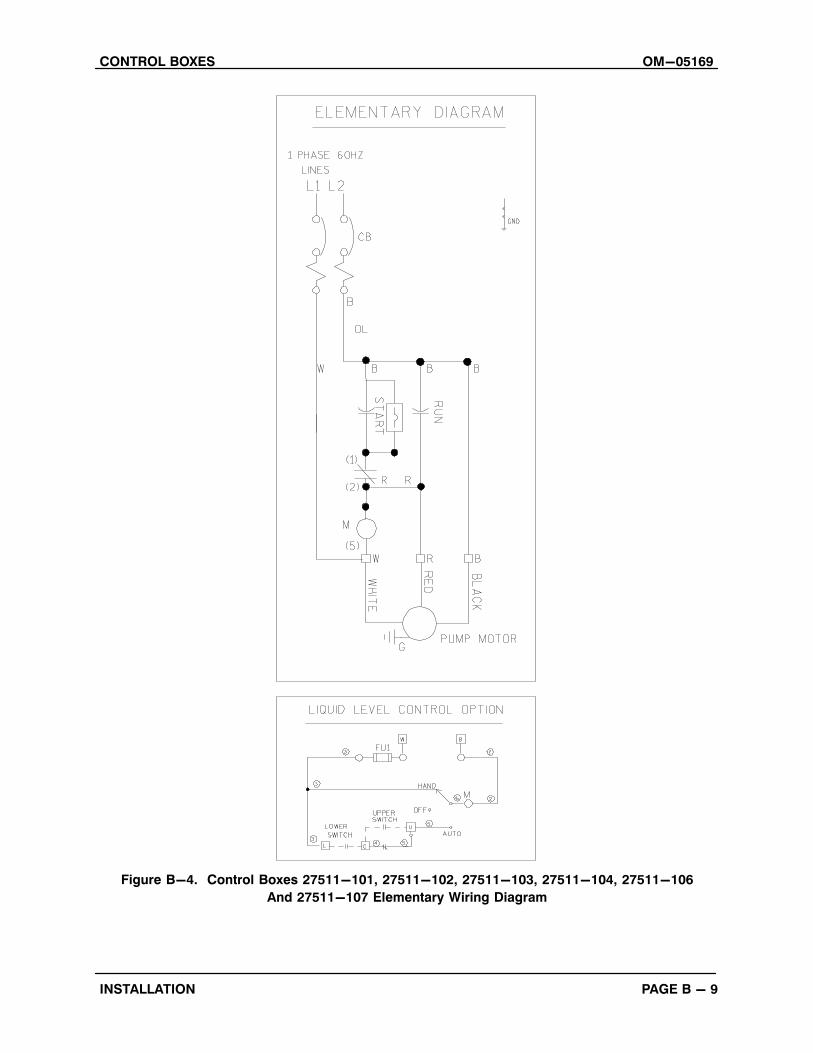
Figure B-4. Control Boxes 27511-101, 27511-102, 27511-103, 27511-104, 27511-106
And 27511-107 Elementary Wiring Diagram

OM-05169 CONTROL BOXES
PAGE B - 10 INSTALLATION
WIRING DIAGRAM
Figure B-5. Control Box 27511-105 Pictorial Wiring Diagram

CONTROL BOXES OM-05169
PAGE B - 11INSTALLATION
Figure B-6. Control Box 27511-105 Elementary Wiring Diagram
CONTROL BOXES OM-05169
OPERATION PAGE C - 1
OPERATION - SECTION C
Review all SAFETY information in Section A.
Follow the instructions on all tags, labels and
decals attached to the control box.
The electrical power used to operatethis control box is high enough to causeinjury or death. Make certain that the tiehandle in the control box is in the OFFposition and locked out, or that the power supply to the control box has beenotherwise cut off and locked out, beforeattempting to open or service the control box. Tag electrical circuits to prevent accidental start‐up.
Obtain the services of a qualified electrician to make all electrical connections, and to troubleshoot, test and/orservice the electrical components of thecontrol box.
CONTROL BOX FUNCTION
The control box is not designed to be explosion‐proof. Do not operate in an explosive atmosphere.
The control box is provided to facilitate operation of
the pump. It contains controls for starting and stop
ping the pump, and provides overload protection
for the pump motor. The pump control is equipped
with an automatic liquid level sensing device, also
contained within the control box.
The control box provides overload protection and power control. Do not connect the pump motor directly to the incoming power lines.
Since operation of the pump motor is dependent upon the quality and performanceof the electrical controls, the pump warranty is valid only when controls have beenspecified or provided by The Gorman‐Rupp Company.
Component Function
The control box contains the following hand‐oper
ated switches and controls:
� The tie handle operates the control box cir
cuit breakers. In the OFF position, the tie
handle opens the circuit breakers to inter
rupt incoming power through the control
box and prevent pump operation. In the ON
position, it closes the circuit breakers to per
mit pump operation. The circuit breakers will
open or “trip” automatically in the event of a
short circuit overload current. When tripped,
move the tie handle to OFF and back to ON
to reset the circuit breakers.
� The circuit breaker also provides
over‐current protection. The breaker will trip
automatically if the current drawn by the mo
tor exceeds design specifications. Allow 10
seconds for the unit to cool after tripping be
fore resetting.
NOTEIf the circuit breaker trips, do not reset it immedi
ately. Wait at least ten minutes before resetting the
tie handle back to the ON position. If the overload
unit continues to trip, operational problems exist.
CONTROL BOXESOM-05169
OPERATIONPAGE C - 2
� A Hand‐Off‐Auto switch is provided as part
of the liquid level device. This switch is to be
used as follows. In the HAND position, the
switch closes the circuit to permit pump op
eration until the switch is moved to the OFF
position. In the OFF position, the switch in
terrupts incoming power through the control
box and prevents pump operation. In the
AUTO position, sensors will automatically
turn the pump on or off depending on the
level of the liquid being pumped. Use only
the Hand‐Off‐Auto switch to turn pump on
and off. Do not use the circuit breaker toggle
switch to manually turn the pump on and off.
Always terminate incoming power to the control
box before investigating control box circuitry prob
lems.
Always terminate power to the controlbox before performing service functions.
Power through the control box may be terminated
by moving the tie handle to the OFF position, there
by opening the circuit breakers. This stops the
pump, but does not terminate incoming power
through the field wiring connected to the control
box.

CONTROL BOXES OM-05169
TROUBLESHOOTING PAGE D - 1
TROUBLESHOOTING - SECTION D
Review all SAFETY information in Section A.
The electrical power used to operatethis control box is high enough to causeinjury or death. Obtain the services of aqualified electrician to troubleshoot,test and/or service the electrical components.
Many of the probable remedies listed in the troubleshooting chart below require use of electrical test instru
ments; for specific procedures, see Electrical Testing at the end of the troubleshooting chart.
When troubleshooting, also refer to the technical information accompanying the pump and optional equip
ment.
TROUBLESHOOTING CHART
TROUBLE POSSIBLE CAUSE PROBABLE REMEDY
PUMP FAILS TOSTART, OVERLOADUNIT NOT TRIPPED(MANUAL MODE)
Power source incompatiblewith control box.
No voltage at line side of circuit breaker.
No voltage at line terminalson bottom of overload unit incontrol box.
Correct power source.
Check power source for blown fuse, openoverload unit, broken lead, or loose connection.
Check power source for blown fuse, opendisconnect, broken wire, or loose connection.
OVERLOAD UNITTRIPS
Low or high voltage, or excessive voltage drop betweenpump and control box.
Power input phases not balanced.
Control box not compatiblewith pump.
Foreign object locking impeller or bearing frozen.
Motor windings short‐circuited.
Measure voltage at control box. Check thatwiring is correct type, size, and length. (SeeField Wiring Connections, Section B).
If imbalance exceeds 1 percent, notify powercompany.
Electrical data on control box and pumpname plate must agree. Replace control box ifnot in agreement.
Remove foreign material or replace damagedbearing. If bearing is damaged, check for water in motor housing.
Check motor windings with ohmmeter.

OM-05169 CONTROL BOXES
TROUBLESHOOTINGPAGE D - 2
ELECTRICAL TESTING
Be certain to refer to the wiring diagram(s)in the Installation Section of this manual before reconnecting any electrical components which have been disconnected.
Test Equipment
A volt/amp/ohmmeter and megohmeter of ade
quate range and quality will be required to conduct
the electrical tests. The suggested equipment indi
cated below is commercially available, or an equiv
alent substitute may be used.
Equipment Use
Ammeter/Voltmeter
To check AC Voltageand current (amperage)
Ohmmeter To measure resistance(ohms) to ground
Voltage Imbalance
Each phase of the incoming three‐phase power
must be balanced with the other two as accurately
as a commercial voltmeter will read. If the phases
are out of balance, contact your power company
and request that they correct the condition.
Capacitors
The start capacitor is designed to split the electrical
phase during the initial power surge at motor start
up. The start capacitor is controlled by the start
relay at motor startup. When the motor reaches
load speed, the start relay cuts out and permits the
run capacitor to maintain operation. Both the start
and run capacitors are located in the control box.
Before disconnecting the capacitor leads,discharge the capacitors; use a screwdriver with an insulated handle, and place theblade across the two terminals of each capacitor to short the terminals.
Zero‐balance the ohmmeter set to read RX100K,
and test the capacitors as follows:
a. Disconnect the capacitor leads, and remove
the resistor from the start capacitor.
b. Place a test lead against each of the termi
nals of the start capacitor for a few seconds.
If the ohmmeter needle moves toward zero
then slowly drifts back to the left, the capaci
tor is good. If the needle remains at infinity
(∞) the capacitor is open; if the needle re
mains at zero, the capacitor is shorted. In ei
ther case, the capacitor must be replaced.
c. Test the run capacitor as in b. In addition,
test the metal run capacitor for shorts to
ground by touching one test lead to the ca
pacitor case and the other lead to each of
the capacitor terminals in turn. The ohmme
ter should read infinity (∞); if it does not, the
capacitor is grounded and must be re
placed.
Start Relay
The start relay is located in the control box.
Disconnect the two wires from relay terminal 2. Use
a zero‐balanced ohmmeter set to read RX100K,
and touch one lead to relay terminal 2 and the other
to relay terminal 5. The resistance reading should
be between 4000 to 6000 ohms; if the reading is
not in this range, the start relay is defective and
should be replaced.
NOTERepair of individual electrical components is not
recommended. Replace defective and/or malfunc
tioning components.