Embed Size (px)
Citation preview

1
The Islamic University of GazaFaculty of Engineering
Civil Engineering Department
Environmental Engineering(ECIV 4324)
Instructor: Dr. Abdelmajid NassarLect. 24-25
Waste Water treatment

Composition of WW
Suspended Solids
Biodegradable Organics
Pathogens
Body waste, food waste rags,
paper, biological cells
Soluble organics
Bacteria, virus
etc.
Protein (40-60%) –
amino acids
Carbohydrates 25-50% -
sugars starch, cellulose
Lipids (10%)- fats,
oils and grease
Contain Carbon – exert an oxygen demand


Wastewater Treatment Plants
Municipal treatment is divided into: Primary, Secondary and Tertiary
Primary Treatment – removes solid materials from stream-Large debris may be removed by screens or reduced in size by grinding device.
Inorganic solids are removed by the grit chamber
Much of the organic suspended solids are removed by sedimentation
Primary treatment removes 50% SS and 30% BOD

Wastewater Treatment Plants
• Secondary Treatment
Consist of the biological conversion of colloidal organics into biomass – this is then removed by sedimentation
Contact is maintained between the MO and the organics by:
1. Suspending biomass in a reactor – Activated Sludge System
2. Passing the wastewater over a film of biomass attached to a solid - Trickling Filter

Type 2 Settling –Flocculating particles in dilute suspension
Stokes law cannot be used as size, shape and SG are changing. Settling velocity is determined by experimentation using a column of approx. depth 2m
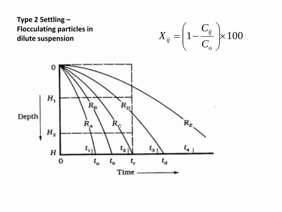
Type 2 Settling –Flocculating particles in dilute suspension 1001
o
ij
ijC
CX

ExampleSetting column analysis of flocculatingparticles A column analysis of flocculatingsuspension is run in the apparatus shownbelow. The initial solids concentration is 250mg/L. the resulting matrix is shown below.What will be the overall removal efficiency of asetting basin which is 3 m deep with adetention time of 1 h and 45 min?

Time of sampling, min
Depth,
m
30 60 90 120 150 180
0.5 133* 83 50 38 30 23
1.0 180 125 93 65 55 43
1.5 203 150 118 93 70 58
2.0 213 168 135 110 90 70
2.5 220 180 145 123 103 80
3.0 225 188 155 133 113 95
*Results of suspended solids test on sample Ci mg/L
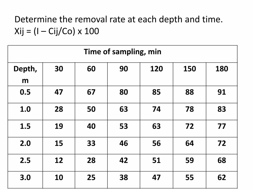
Determine the removal rate at each depth and time.Xij = (I – Cij/Co) x 100
Time of sampling, min
Depth,
m
30 60 90 120 150 180
0.5 47 67 80 85 88 91
1.0 28 50 63 74 78 83
1.5 19 40 53 63 72 77
2.0 15 33 46 56 64 72
2.5 12 28 42 51 59 68
3.0 10 25 38 47 55 62
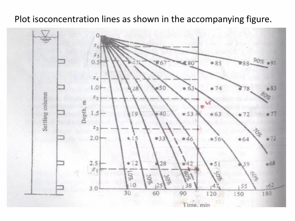
Plot isoconcentration lines as shown in the accompanying figure.

Construct vertical line at t0 = 105 min.
From the figure, approximately 43 percent of the solidswill reach the 3-m depth in t0, they will be 100 percentremoved. Some percentage of the remaining particleswill be removed. Working upward along the to line,determine increments of removal and depths to themidpoint of these increments.

R Zi r. Zi
0.07 2.6 0.18
0.1 1.8 0.18
0.1 1.2 0.12
0.1 0.8 0.08
0.1 0.45 0.04
0.1 0.15 0.01
Ʃ r Zi = 0.61
•Determine the removal efficiency, R = ro +
= 0.43 +
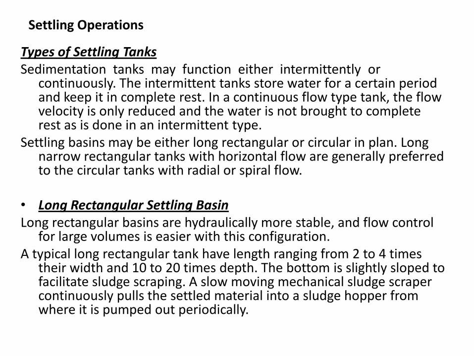
Types of Settling TanksSedimentation tanks may function either intermittently or
continuously. The intermittent tanks store water for a certain period and keep it in complete rest. In a continuous flow type tank, the flow velocity is only reduced and the water is not brought to complete rest as is done in an intermittent type.
Settling basins may be either long rectangular or circular in plan. Long narrow rectangular tanks with horizontal flow are generally preferred to the circular tanks with radial or spiral flow.
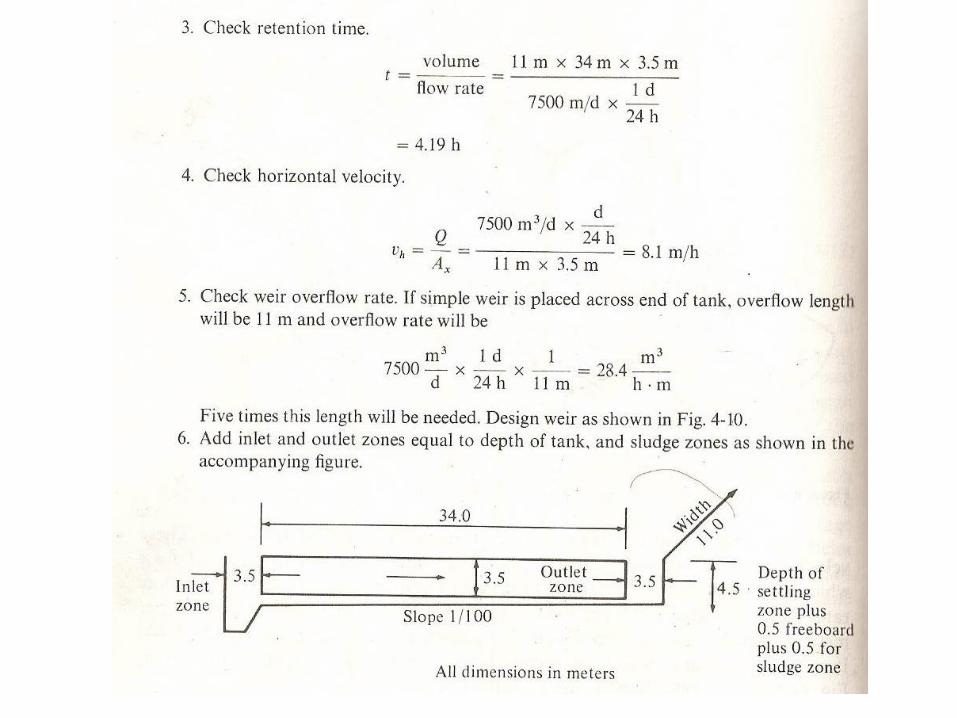
• Long Rectangular Settling BasinLong rectangular basins are hydraulically more stable, and flow control
for large volumes is easier with this configuration. A typical long rectangular tank have length ranging from 2 to 4 times
their width and 10 to 20 times depth. The bottom is slightly sloped to facilitate sludge scraping. A slow moving mechanical sludge scraper continuously pulls the settled material into a sludge hopper from where it is pumped out periodically.
Settling Operations

Long Rectangular Settling Basin

• A long rectangular settling tank can be divided into four different functional zones:Inlet zone: Region in which the flow is uniformly distributed over the cross section such that the flow through settling zone follows horizontal path.Settling zone: Settling occurs under quiescent conditions.Outlet zone: Clarified effluent is collected and discharge through outlet weir.Sludge zone: For collection of sludge below settling zone.
• Inlet and Outlet Arrangement• Inlet devices: Inlets shall be designed to distribute the water equally
and at uniform velocities. A baffle should be constructed across the basin close to the inlet and should project several feet below the water surface to dissipate inlet velocities and provide uniform flow;
• Outlet Devices: Outlet weirs or submerged orifices shall be designed to maintain velocities suitable for settling in the basin and to minimize short-circuiting. Weirs shall be adjustable, and at least equivalent in length to the perimeter of the tank. However, peripheral weirs are not acceptable as they tend to cause excessive short-circuiting.

Weir Overflow Rates
Large weir overflow rates result in excessive velocities at the outlet. These velocities extend backward into the settling zone, causing particles and flocs to be drawn into the outlet. Weir loadings are generally used up to 300 m3/d/m. It may be necessary to provide special inboard weir designs as shown to lower the weir overflow rates.
Inboard Weir Arrangement to Increase Weir Length
http://www.nptel.iitm.ac.in/courses/Webcourse-contents/IIT-KANPUR/wasteWater/Lecture%206.htm
Sedimentation in Water Treatment
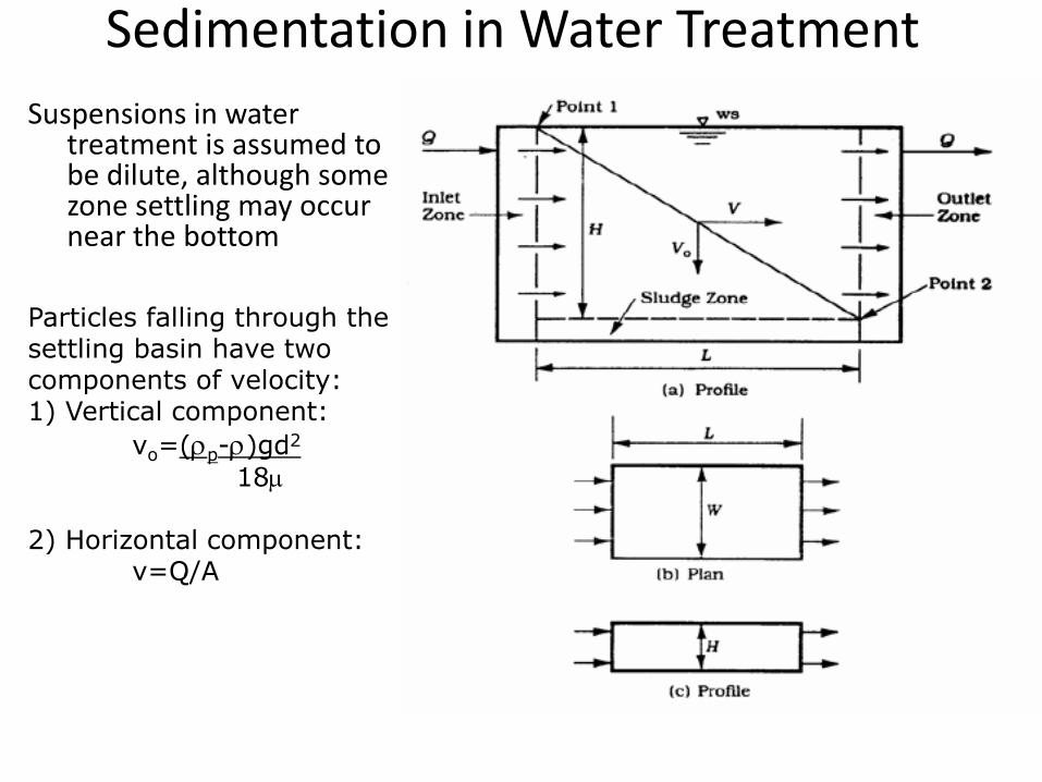
Suspensions in water treatment is assumed to be dilute, although some zone settling may occur near the bottom
Particles falling through the settling basin have two components of velocity:1) Vertical component:
vo=(rp-r)gd2
18m
2) Horizontal component: v=Q/A
Sedimentation in Water Treatment
Sedimentation in Water Treatment

• Design Details• The depth is not a factor in determining the size of particles that can be removed
completely• The determining factor is Q/Ap = overflow rate, (m3/m2-h), V0 or q0,
• Depth is a factor in flocculent settling• Depth of basin for discrete particles = 2.5 to 3m (3 to 4 for Flocculent particles)• Overflow rate - discrete (1.0 to 2.5 m/h) Flocculent (0.6 to 1 m/h)• Detention time – discrete 2 to 4 hrs and flocculent 4 to 6 hrs• Horizontal flow velocity light flocculent – not be greater than 9 m/h• Horizontal flow velocity -Heavier discrete - 36m/h• Weir overflow rate – 6 m3/h /meter of weir (light floc) & 14 for discrete particles• Tank dimensions: L:B = 3 to 5:1. Generally L= 30 m (common) maximum 100 m.
Breadth= 6 m to 10 m. Circular: Diameter not greater than 60 m. generally 20 to 40 m.
• Slopes: Rectangular 1% towards inlet and circular 8%.
Sedimentation in Water Treatment

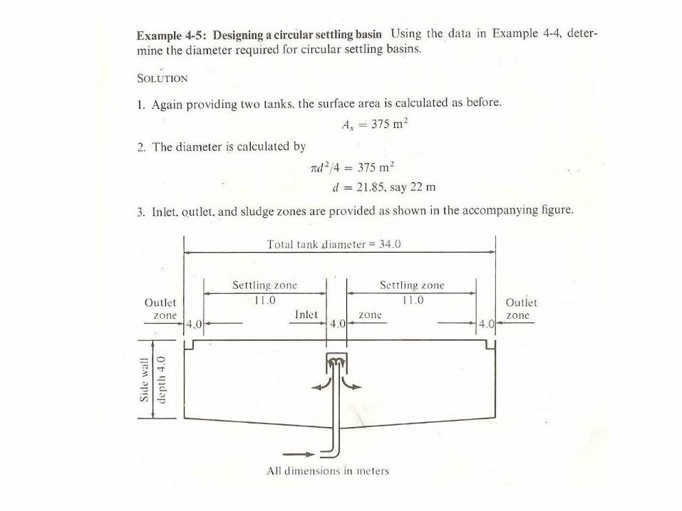
Work Example
Circular TanksFunctions similar to a rectangular tank but flow regime is
different. Flow enters at the center and is baffled to flow radially to the perimeter. The horizontal velocity is continually decreasing as distance from center increases. Thus the path of a particle is parabola rather than a straight line.
Main advantage:-Sludge removal mechanisms are simpler and less
maintenance. -Entire circumference is used for overflow.-Tanks should be limited to 30m for flow control
Circular Tank