Embed Size (px)
Citation preview

VULCAN Pool HeaterInstallation & Operating Manual
1
ENG
LISH
Important Notes!
Thank you for purchasing the VULCAN direct electric swimming pool heater manufactured in England to the highest standards.
To ensure your new heater will give years of trouble free service please carefully read the following instructions. Incorrect installation will aff ect your warranty.
Do not discard this manual, please retain for future reference.
Product Overview
Fig 1.
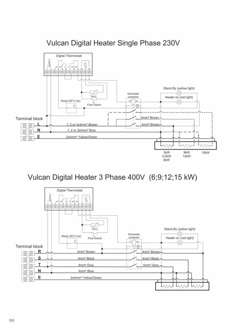
DIGITAL Version
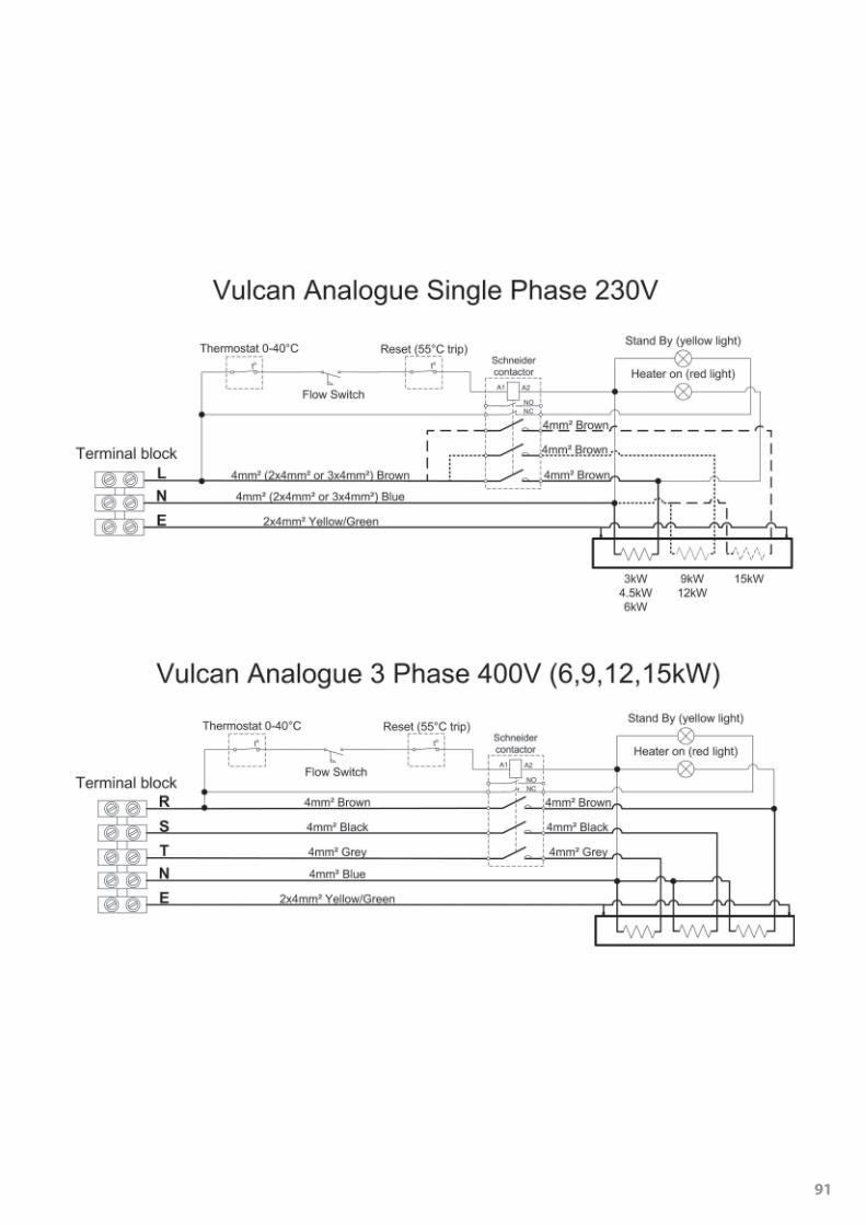
ANALOGUE Version
2
Positioning
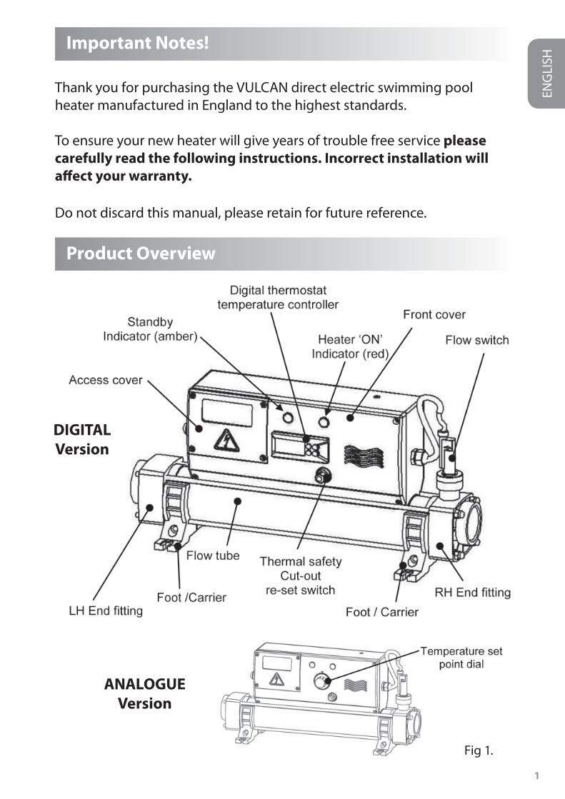
Your heater must be horizontally or vertically sited allowing suffi cient space for pipe connections and wiring, it should be screw fi xed securely to a fi rm base or wall.
NOTE: See fi gure 2 for details of the foot arrangement when securing to the wall or fl oor.
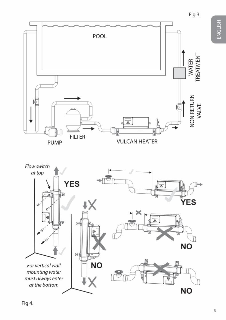
The heater should be installed at a low point in the fi ltration system.It should be positioned downstream (after) of the fi lter and upstream (before) of any dosing or other water treatment plant. (see fi g.3)
NOTE : If the fl ow direction is reversed (explained later in thisbooklet) the heater must remain sited after the fi lter.
Factory set fl oor mount ‘Foot position’
To reset for wall mount option,
undo the bolts and re-assemble in the vertical position as
shown.
Floor mount ‘Foot position’
Wall mount ‘Foot position’
Fig 2.
ENG
LISH
3
ENG
LISH
Flow switchat top
For vertical wallmounting water
must always enterat the bottom
Fig 3.
Fig 4.
PUMPFILTER
POOL
VULCAN HEATER
NO
N R
ETU
RNVA
LVE
WAT
ERTR
EATM
ENT

4
Pipe Work
It is essential that the pipe work connecting to and from the heaterhas a minimum bore (internal diameter) of 1¼” (32mm). To assist correct air purging and to ensure the heater remains completely full of water during operation, the return pipe which carries the water back to the pool must incorporate a safety loop or ‘kick-up’ in the pipe as close as possible to the heater (see fi g 4)
NOTE: When coupling to a fl exible pipe a safety loop can simply be created by routing the pipe up and over an obstacle.Remember to use pipe clips to securely fasten all hose connections.
Weather Protection
The heater must be installed within a dry weather proof enclosure.
Caution! If the heater is not used during winter months it must be drained toprevent frost damage.
Electrical Connection
The heater must be installed in accordance with the country / regional requirements & regulations. In any event the work must be carried out by a qualifi ed electrician, who will provide a certifi cate of conformity upon completion of the work. The power supply must be fi tted with a RCD. If required your electrician may replace the supplied cable entry gland with a larger size to secure the cable powering the heater, this will not aff ect your warranty if carried out by a qualifi ed electrician.
Cable section: This should be calculated at 5-amp / mm2 for distances up to 20 metres (these sections are indicative and should be checked and adapted if necessary for cable lengths over 20 metres.
ENG
LISH
Remove Access Coverto make the electrical
connections(Qualifi ed electricians only)
Fig 5.
5
ENG
LISH
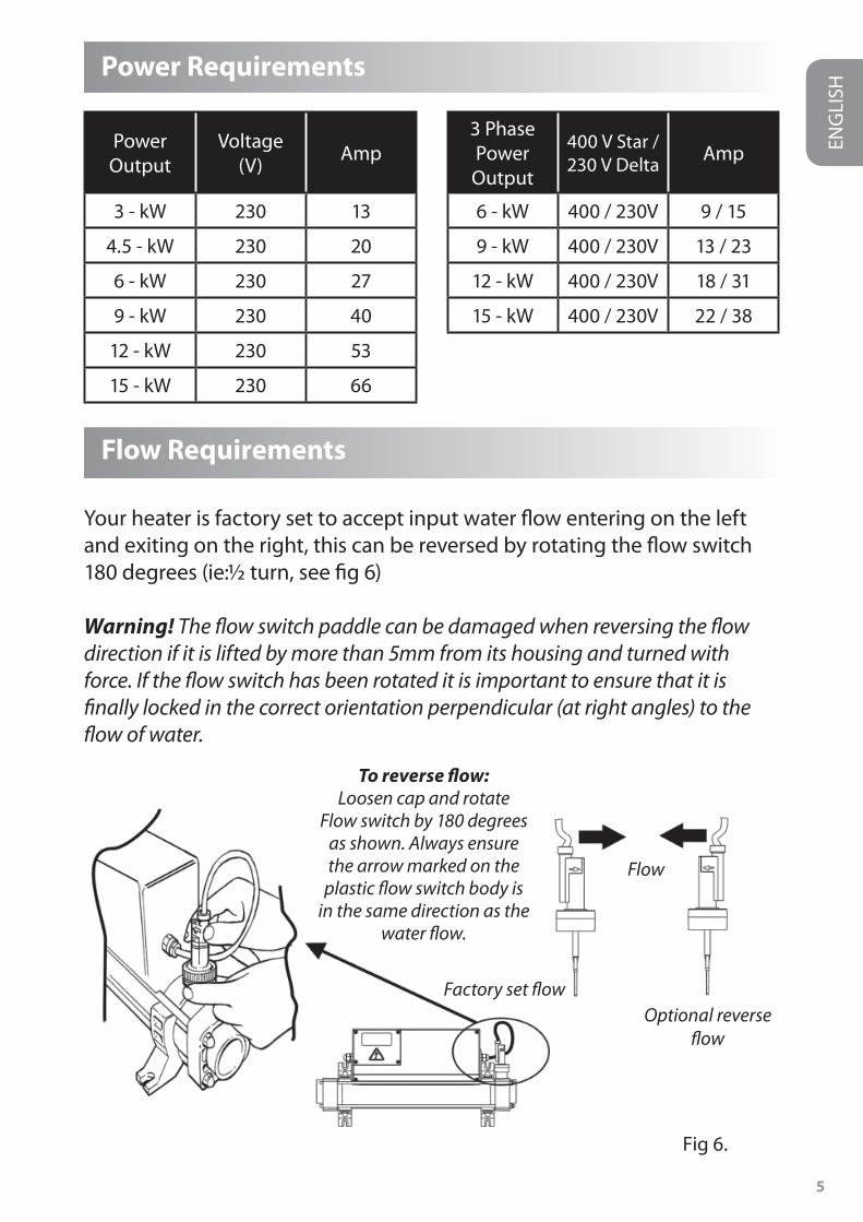
Power Requirements
Flow Requirements
Your heater is factory set to accept input water fl ow entering on the left and exiting on the right, this can be reversed by rotating the fl ow switch 180 degrees (ie:½ turn, see fi g 6)
Warning! The fl ow switch paddle can be damaged when reversing the fl ow direction if it is lifted by more than 5mm from its housing and turned with force. If the fl ow switch has been rotated it is important to ensure that it is fi nally locked in the correct orientation perpendicular (at right angles) to the fl ow of water.
PowerOutput
Voltage(V) Amp
3 - kW 230 13
4.5 - kW 230 20
6 - kW 230 27
9 - kW 230 40
12 - kW 230 53
15 - kW 230 66
3 Phase PowerOutput
400 V Star /230 V Delta Amp
6 - kW 400 / 230V 9 / 15
9 - kW 400 / 230V 13 / 23
12 - kW 400 / 230V 18 / 31
15 - kW 400 / 230V 22 / 38
To reverse fl ow: Loosen cap and rotate
Flow switch by 180 degrees as shown. Always ensure the arrow marked on the
plastic fl ow switch body is in the same direction as the
water fl ow.
Factory set fl owOptional reverse
fl ow
Flow
Fig 6.
6
The fl ow rate of water into the heater must not exceed 17,000 litres per hour (3,740 UK gallons/hour) A higher fl ow rate will require the installation of a bypass to prevent damage to the heater elements. The heater will not operate unless the following minimum fl ow rates are achieved ie:
1,000 litres / hour (220 UK gallons/hour) for 3 ~ 6-kW heaters and4,000 litres / hour (880 UK gallons/hour) for 9 ~ 15-kW heaters.
Water Quality
The water quality must be within the following limits:PH 6.8 - 8.0TA (Total alkalinity) 80—140ppm (parts per million)Chloride Content MAX: 150 mg/litreFree Chlorine: 2.0 mg/litreTotal Bromine: Max 4.5 mg/litreTDS (Total Dissolved Solids) / Calcium hardness 200— 1,000ppm
Water chemistry is complicated if in doubt seek expert advise.
Operating Your Heater
Upon completion of the installation, run the water-circulating pump to purge the system & heater of air (i.e. Remove any trapped air in thesystem & heater). TIP: You can encourage air out of the heater fl ow tube by gently elevating the exit port of the heater when the pump is running.On initial power up of the heater the amber light should illuminate.
The heater will only switch ‘On’ (red light indicator illuminated) and the amber light switching ‘Off ’ when the following criteria are met ie:
Water circulating pump is ‘On’ delivering in excess of the minimum fl ow • rate of water (see fl ow requirement information)
Water temperature set point (required temperature) is set to a higher • value than that of the water.
ENG
LISH
7
Analogue set-up
Rotate the Temperature ’Set point’ dial located on the front of the unit (see fi g 1) to the required water temperature.
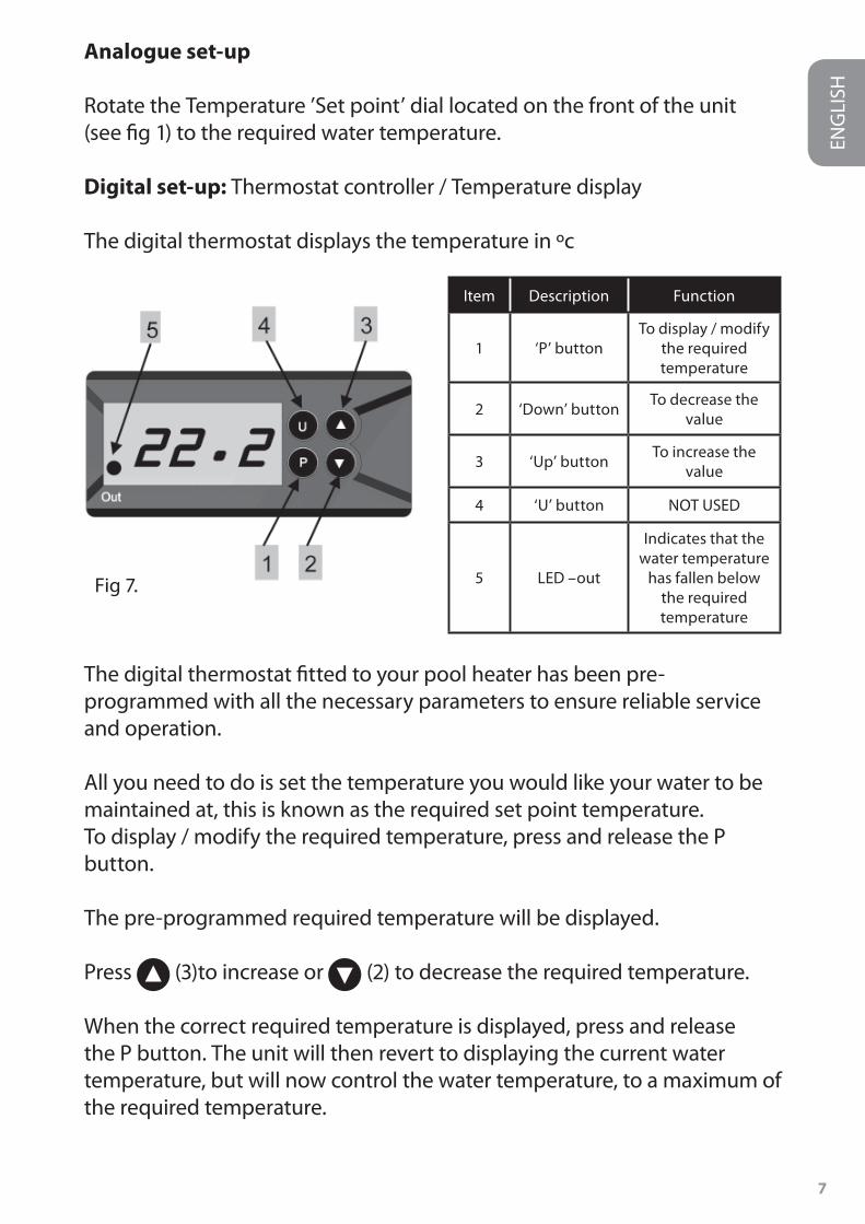
Digital set-up: Thermostat controller / Temperature display
The digital thermostat displays the temperature in ºc
The digital thermostat fi tted to your pool heater has been pre-programmed with all the necessary parameters to ensure reliable service and operation.
All you need to do is set the temperature you would like your water to be maintained at, this is known as the required set point temperature.To display / modify the required temperature, press and release the P button.
The pre-programmed required temperature will be displayed.
Press (3)to increase or (2) to decrease the required temperature.
When the correct required temperature is displayed, press and release the P button. The unit will then revert to displaying the current water temperature, but will now control the water temperature, to a maximum of the required temperature.
ENG
LISH
Item Description Function
1 ‘P’ buttonTo display / modify
the required temperature
2 ‘Down’ button To decrease the value
3 ‘Up’ button To increase the value
4 ‘U’ button NOT USED
5 LED –out
Indicates that the water temperature
has fallen below the requiredtemperature
Fig 7.
8
ENG
LISH
Time switching delay
To prevent overheating of the components within the heater caused by frequent ’On’ and ’Off ’ switching (cycling) the digital thermostat has been pre-programmed with a time delay function. This prevents rapid fl uctua-tions in water temperature from switching the heater ’On’ and ’Off ’ more than once in a two minute period. The time delay mode is indicated by the fl ashing of the Red indicator (5) on the digital thermostat (see fi g.7)
Diff erential: When the water has reached the required temperature the heater will switch ’Off ’ and will not switch back ’On’ until the water temperature has dropped by 0.6º C. This value is known as the diff erential and is also in place to prevent overheating to the switch components caused by cycling.
High temperature alarm
Your heater has a high temperature fail-safe relay linked to a visual high tem-perature alarm display. This alarm is shown as ‘HI’ fl ashing within the temperature display window. This alarm is activated if the water temperature is 2º C (or more) above the required temperature. As soon as the water temperature falls back to the required temperature the alarm will stop fl ashing and the heater will automatically reset and operate as normal.
Please note: If you decrease the required temperature by 2º C (or more) below the current water temperature this will also result in the high temperature alarm being displayed.
Function Testing
Q: How long will it take to heat my pool?A: Assuming no heat losses, and a heater sized in the ratio 1.5-kW per 1,000 UK gallons of water (4,545-litres): it will take 2 days of continuous running to raise the temperature of a pool from tap temperature to swimming temperature. Heat loss will slow the heating process, particularly during periods of cold weather, hence the higher the water temperature is to be maintained above average ambient air temperature, the slower the heating process will become.

9
ENG
LISH
The only infl uencing factors are the level of insulation and the location of the pool with regard to wind shelter.
Useful advice: To reduce running costs and speed up the heating process; Insulate the pool wherever possible. A fl oating solar cover is an essential minimum to retain heat.
Quick Function Test
Observe the main electricity meter when the heater is on (ie: red light ‘On’) and then observe it again when the heater is in the standby mode (ie: amber light ‘On’) The test should show that the meter is recording more electricity being used by the heater when the red light is ‘On’. It is impossible for an electric heater to waste energy, if it is drawing power then that power will be turned into heat that will be trans-ferred to the water.
Accurate Function Test
If a more accurate test is required to confi rm that your heater is delivering the specifi ed heat output, two electricity meter readings will need to be taken from the properties main electricity meter, with an exact one hour interval (ie: take one meter reading and then a second reading exactly one hour later) then by subtracting the fi rst reading from the second reading the number of units (kilo watts kW) consumed can be calculated. Note that your heater is also rated in kW hours.
The pool pump and heater will need to be running continuously during the test (ie: with the heater red light ’On’) To avoid inaccurate results when performing this test, it is important to refrain from using other high current consuming appliances in the property (such as tumble dryer, showers, cookers etc).
A large domestic pool pump of 1 horsepower will draw less than 1kW in a one hour period. The conclusion of the test should prove that for example a 6kW heater and a ½ horsepower pump will draw between6.3-kW ~ 6.5-kW in one hour. It is impossible for an electric heater to waste energy, if it is drawing power then that power will be turned into heat that will be transferred to the water.

10
ENG
LISH
Trouble Shooting – Analogue
HEATER WILL NOT SWITCH FROM STANDBY (AMBER LIGHT ) TO ON (RED LIGHT)
In most cases this will be the result of one of the following points notbeing met.
Possible cause 1: The set point temperature has been achieved. To confi rm increase the set point value by turning the temperature set point dial to a value greater than the current water temperature.
Possible cause 2: The high limiting thermostat has tripped.Remedy: Remove button cover and press red button to re-set (see fi g 8) If a positive click is felt, the cause of the tripping must be investigated and could be caused by a debris build-up or air pocket trapped inside the fl ow tube of the heater.
Possible cause 3: Insuffi cient fl ow.If using a cartridge fi lter: Confi rm this by running the system with thecartridge removed from your pump & fi lter unit, this will supply the heater with the maximum fl ow rate your unit is capable of. If the heater then switches ’On’ (ie: red light ’On’) a blocked cartridge can be confi rmed to be the cause. The cartridge should be cleaned or replaced.
If using a sand fi lter: Check the pressure indicator on your sand fi lter and back wash if necessary.
Fig 8.
11
ENG
LISH
Note: In some cases the high limit thermostat tripping and a low fl ow rate can be linked ie: when a fi lter becomes choked air can be drawn into the fi ltration system and become trapped inside the heater so causing the thermostat to trip.
Trouble Shooting – Digital
HEATER WILL NOT SWITCH FROM STANDBY (AMBER LIGHT ) TO ON (RED LIGHT)
In most cases this will be the result of one of the following points notbeing met.
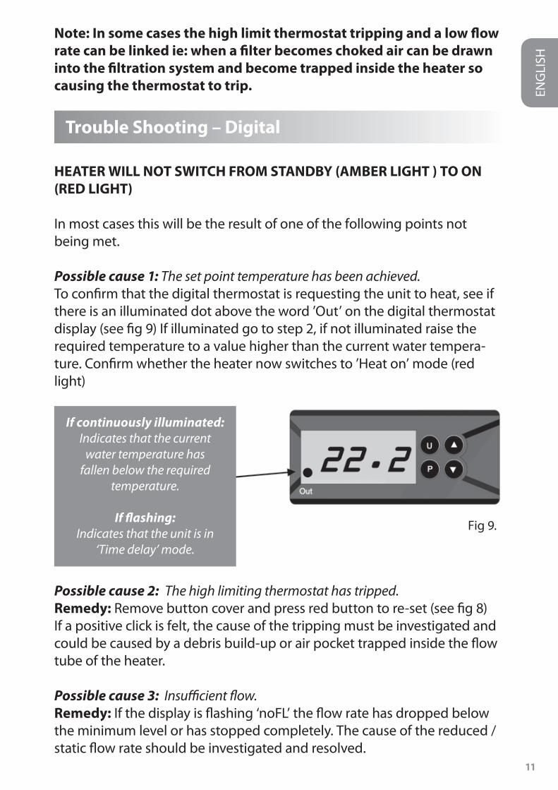
Possible cause 1: The set point temperature has been achieved.To confi rm that the digital thermostat is requesting the unit to heat, see if there is an illuminated dot above the word ’Out’ on the digital thermostat display (see fi g 9) If illuminated go to step 2, if not illuminated raise the required temperature to a value higher than the current water tempera-ture. Confi rm whether the heater now switches to ’Heat on’ mode (red light)
Possible cause 2: The high limiting thermostat has tripped.Remedy: Remove button cover and press red button to re-set (see fi g 8)If a positive click is felt, the cause of the tripping must be investigated and could be caused by a debris build-up or air pocket trapped inside the fl ow tube of the heater.
Possible cause 3: Insuffi cient fl ow.Remedy: If the display is fl ashing ‘noFL’ the fl ow rate has dropped below the minimum level or has stopped completely. The cause of the reduced / static fl ow rate should be investigated and resolved.
Fig 9.
If continuously illuminated:Indicates that the current
water temperature has fallen below the required
temperature.
If fl ashing:Indicates that the unit is in
‘Time delay’ mode.
12
General Trouble Shooting
NO LIGHT APPEARS ON THE HEATER WHEN IT IS SWITCHED ’ON’
Possible cause: Power failure external to the heaterRemedy: Check any fuses, RCD or other switch components installed in the supply cable. Note: the heater is not fi tted with a fuse.
THE FLOW TUBE DOES NOT FEEL WARM
Due to the high effi ciency of your electric heater no warmth should be detectable from the fl ow tube of the heater.
The most likely causes of the fl ow tube feeling warm are:-Possible cause 1: The heater has been positioned in direct sunlight.Possible cause 2: An air pocket is trapped inside the heater particularly if the tank feels warmer at the highest point of the tank (as air rises).
THE WATER ENTERING MY POOL DOES NOT FEEL MUCH WARMER
The temperature gain of the water after it has passed through the heater will be directly proportional to the volume of water being pumped inrelationship to the power output of the heater.
For example: A 6-kW heater, when connected to a 4,000 litre / hour pump, will produce a lift in temperature of approximately 1.2 C (almost undetectable to the human hand) however, as the water being heated is re-circulated from a single body of water, the time required to heat itremains unaff ected by the volume of fl ow. A popular misconception is that slowing down the fl ow rate will speed up the heating process.
ENG
LISH

13
ENG
LISH
RoHS Compliance Statement
Elecro Engineering Limited certify that our Electric Swimming Pool Heater Range complies in accordance with RoHS Directive 2002/95/EC on the
restriction of hazardous substances.
Waste Of Electrical / Electronic Equipment
This product complies with EU directive 2002/96/ECDo Not dispose of this product as unsorted municipal waste.
This symbol on the product or on it’s packaging indicates that this product should not be treated as household waste. Instead it should be handed over to the applicable collection point for the recycling of electrical and electronic equipment.
By ensuring this product is disposed of correctly you will help prevent potential negative consequences for the environment and human health, which could otherwise be caused by inappropriate waste handling of this product. The recycling of materials will help to conserve natural resources.
For more information please contact your local Civic offi ce, your household waste disposal service or the retailer where you purchased the product.
Product Overview
14
Guarantee
Your heater is guaranteed from the date of purchase against faulty workmanship and materials ie: 2 years guarantee for incoloy heating element products and 3 years guarantee for titanium heating element products.
The manufacturer will replace or repair, at it’s discretion, any faulty units or components returned to the company for inspection.Proof of purchase may be required.
The manufacturer will not be liable in cases of incorrect installation of the heater, inapropriate use or neglect of the heater.
CE Declaration Of ConformityThe manufacturer declares that the herewith products or ranges
ELECTRIC SWIMMING POOL HEATER RANGE
Are in conformity with the provisions:of the ELECTROMAGNETIC COMPATIBILITY directive 89/336/EEC, as amended 93/068/EEC. Controlled by AEMC Measures laboratory—
technical report no P96045T
The harmonised standards have been applied: EN 55014—EN 55104EN 55011EN 55022CEI 801-4CEI 801-2CEI 801-3
of the LOW VOLTAGE directive 73/23/EEC.The harmonised standards have been applied
EN 60335-2-35
Product Overview
ENG
LISH
90
91

11 Gunnels Wood Park | Stevenage | Hertfordshire | SG1 2BH | United Kingdomt: +44 (0) 1438 749 474 | f: +44 (0) 1438 361 329 | e: [email protected]
© Copyright 2011 Z-INS-VULC-EVO