Embed Size (px)
Citation preview

V.S.B. ENGINEERING COLLEGE, KARUR
Department of Mechanical Engineering
III year Question Bank
ME 8595 – THERMAL ENGINEERING - II
UNIT I
STEAM NOZZLE
Part A
1. What is meant by super saturation in steam nozzles?
Owing to the high velocity, the residence time of steam in the steam nozzle is small, and there may
not be sufficient time for necessary heat transfer and the formation of liquid droplet. Consequently the
condensation of the steam may be delayed for a little while. This phenomenon is known as super
saturation.
2. Define stagnation enthalpy.
Stagnation enthalpy is the enthalpy of a flow at a stagnation point. It is the enthalpy at
a stagnation point (zero velocity) if the flow is brought to a stop from velocity. Total enthalpy is defined at
every point in a flow field.
3. What are the different forms of steam nozzles?
Convergent nozzles
Divergent nozzles
Convergent divergent nozzles
4. Define coefficient of nozzle or nozzle efficiency.
(Actual enthalpy drop) h1 – h3
Nozzle efficiency = ----------------------------- = ------------
(Isentropic enthalpy drop) h1 – h2
5. What is the effect of friction on the flow through a steam nozzle? (May/June 2014)
The expansion will not be isentropic and enthalpy drop is reduced
The dryness fraction of the steam is increased
The specific volume of steam is increased
6. What are the differences between super saturated flow and isentropic flow in steam
nozzles?
Entropy is not constant, Entropy is constant
Reduction in enthalpy drop, No reduction in enthalpy drop
Mollier diagram could not be used, Mollier diagram can be used to solve the problem.
7. What are the reasons for the drop in velocity of the steam for a given pressure drop in steam nozzle?
Friction between the surface of the nozzle and steam
Due to internal fluid friction in the steam
Due to shock losses
8. What are the effects of super saturation in nozzles?
The dryness fraction of the steam is increased
Entropy and specific volume of the steam are increased
Exit velocity of the steam is reduced
Mass of the steam discharged is increased

9. What are the limits for super saturation in steam nozzles?
The super saturation occurs upto above 0.94 dryness fraction and beyond that the condensation of steam
occurs suddenly and irreversibly at constant enthalpy and then remains in stable condition.
10. What are the main functions of steam nozzles?
To supply high velocity jet of steam in steam turbine
To inject feed water in to the boiler in a steam injector
11. Define indicated pressure ratio in steam nozzles.
There is only one value of the ratio (P2/P1), which produces maximum discharge from the nozzle.
That ratio is called Critical Pressure Ratio.
12. What are the factors those change the fluid properties while a fluid flows through a nozzle with no
work or heat transfer?
Change in flow area
Frictional forces
13. Explain super saturated flow (or) metastable flow in steam nozzle.
When super heated steam is expanded isentropically, it starts condensing at its meet with dry saturated
line. But in nozzles, the velocity of steam is high and hence the time available is very less So, the
condensation phenomenon does not start. As a result of this, the steam continues to expand in dry
condition. The steam is said to be supersaturated or metastable state.
14. What are the effects of super saturation?
The super saturation increases the specific volume and entropy of the steam.
Super saturation reduces the heat drop. Thus exit velocity of the steam is reduced.
Super saturation increases the dryness fraction of the steam.
15. What is internal efficiency?
The ratio of total useful heat drop to the total isentropic heat drop is called internal efficiency.
16. Differentiate super saturated flow and isentropic flow.
Entropy is not constant Entropy remains constant Super saturation reduces the heat drop therefore exit
velocity is reduced No reduction in enthalpy drop.
17. Mention the applications of nozzle.
To inject feed water into the boiler in steam injectors.
To maintain, high vacuum in power plant condensers.
To supply, high velocity jet of steam jet in steam turbines.
To remove, air in condenser
18. What are the advantages of convergent divergent nozzle?
The steam enters the nozzle at high pressure with negligible velocity and leaves at high velocity with
low pressure.
Convergent-divergent nozzles are used in back pressure turbine.
19. What is the purpose of divergent portion after the throat section of nozzle?
It accelerates the steam leaving the nozzle.
It does not affect the discharge of steam passing through the nozzle.

20. Define degree of super saturation.
The ratio of super saturation pressures corresponding to the temperature between super saturated regions
is known as the degree of super saturation.
21. Define blading efficiency.
The ratio of the work done on the blades to the energy supplied to the blades is called blading efficiency.
22. What is the back pressure?
The pressure at which the steam leaves the nozzle is known as back pressure, it’s a resistance or force
opposing the desired flow of fluid through pipes, leading to friction loss and pressure drop.
23. Why velocity of steam gets reduced when it moves through nozzle?
The friction between steam and walls of nozzle
Internal friction of steam itself
Shock losses.
24. Define reheat factor.
Reheat factor is the ratio of the cumulative heat to the adiabatic drop from initial condition to exhaust
pressure.
PART B
1. Steam having pressure of 10.5 bar and 0.95 dryness is expanded through a convergent-
divergent nozzle and the pressure of steam leaving the nozzle is 0.85 bar. Find the velocity
at the throat for maximum discharge conditions. Index of expansion may be assumed as
1.135. Calculate mass rate of flow of steam through the nozzle.
2. Dry saturated steam enters a frictionless adiabatic nozzle with negligible velocity at a
temperature of 300oC. It is expanded to pressure of 500 KPa. The mass flow rate is 1 kg/s.
Calculate the exit velocity of the steam.
3. Steam is expanded in a set of nozzles from 10 bar and 200oC to 5 bar. What type of Nozzle is
it? Neglecting the initial velocity find minimum area of the nozzle required to allow a flow of
3 kg/s under the given conditions. Assume that expansion of steam to be isentropic.
4. In a steam nozzle, the steam expands from 4 bar to 1 bar. The initial velocity is 60 m/s and
the initial temperature is 200oC. Determine the exit velocity if the nozzle efficiency is 92%
5. Describe the expression for critical pressure ratio in terms of index of expansion.
6. Dry saturated steam enters a steam nozzle at a pressure of 15 bar and is discharged at a
pressure of 2bar. If the dryness fraction of discharge steam is 0.96, what will be the final
velocity of steam? Neglect initial velocity of steam. If 10% of heat drop is lost in friction,
Examine (find) the percentage reduction in the final velocity.
7. Dry saturated steam at a pressure of 11 bar enters a convergent- divergent nozzle and leaves
at a pressure of 2 bar. If the flow is adiabatic and frictionless, determine: (i) The exit
velocity of steam. (ii) Ratio of cross section at exit and that at throat. Assume the index of
adiabatic expansion to be 1.135.

8. Dry saturated steam at a pressure of 8 bar enters a convergent divergent nozzle and leaves it
at a pressure of 1.5 bar. If the flow is isentropic and if the corresponding expansion index is
1.33, find the ratio of cross-sectional area at exit and throat for maximum discharge.
9. Air at a pressure of 20 bar and at a temperature of 18°C is supplied to a convergent divergent
nozzle having a throat diameter of 1.25 cm and discharging to atmosphere. The adiabatic
index for air is 1.4 and the characteristic constant is 287. Find the weight of air discharged
per minute.
10. Derive an expression for maximum discharge through convergent divergent nozzle for steam.
11. Steam enters a group of convergent-divergent nozzles at a pressure of 22 bar and with a
temperature of 240°C. The exit pressure is 4 bar and 9% of the total heat drop is lost in
friction. The mass flow rate is 10kg/s and the flow up to throat may be assumed friction less.
Calculate 1.The throat and exit velocities, and 2. The throat and exit areas.
12. Air enters a frictionless adiabatic converging nozzle at 10 bar 500 K with negligible
velocity. The nozzle discharges to a region at 2 bar. If the exit area of the nozzle is 2.5 cm2,
find the flow rate of air through the nozzle. Assume for air Cp = 1005 J/kg K and Cv= 718
J/kg K.
UNIT II
BOILERS
Part A
1. What is water level indicator?
It is fitted in front of the boiler and generally present two in number.
It is used to indicate the water level inside the boiler. It shows the instantaneous level of
water is present inside the steam boiler which is necessary for its proper working.
2. Define boiler efficiency.
Boiler efficiency is a measure of how effectively chemical energy in fuel is converted
into heat energy in steam going to the turbines.
3. Define equivalent evaporation from and at 1000C.
It is the amount of water that would be evaporated from water at 100oC to steam at
100oC. By the same amount of heat which was actually absorbed by water and steam under
operating conditions.
4. Define boiler thermal efficiency.
Thermal efficiency is a measure of the effectiveness of the heat exchanger of the boiler. It
measures the ability of the exchanger to transfer heat from the combustion process to the
water or steam in the boiler.
5. Discuss chemical fuel.
Chemical fuels are substances that release energy by reacting with substances around
them, most notably by the process of combustion. Most of the chemical energy released in
combustion was not stored in the chemical bonds of the fuel, but in the weak double bond of
molecular oxygen.
6.
Types of Boiler Fuel.
Diesel/Fuel Oil
Solid Fuel
Renewable Energy (Biomass)

7. What are primary fuels? List some important fuels.
Primary fuels are fuels that are found in nature and can be extracted, captured, cleaned,
or graded without any sort of energy conversion or transformation process. This means that
all processing and collecting of the fuel is done before the fuel is converted into heat or
mechanical work. Coal, Crude oil, Bitumen, Natural gas, Uranium and Thorium
8. Define heating value of fuel.
Heating value is the amount of heat produced by a complete combustion of fuel and it is
measured as a unit of energy per unit mass or volume of substance(kJ/kg)
9. Explain the function of the boiler chimney.
A chimney is an architectural ventilation structure made of masonry, clay or metal that
isolates hot toxic exhaust gases or smoke produced by boiler, stove, furnace from human
living areas.
10. Why is there no chimney in the case of a locomotive boiler?
Chimneys are used with locomotive boilers, but they are fitted on the smoke box. But
recently locomotive engines have started to get shorter chimneys to reduce the air resistance
acting on it when the locomotive is at high speed.
11. What is safety valve?
A safety valve is a valve that acts as a fail-safe. An example of safety valve is a
pressure relief valve (PRV), which automatically releases a substance from a boiler, pressure
vessel, or other system, when the pressure or temperature exceeds preset limits
12. Explain various types of draughts used in usual practice.
Boiler draught is the pressure difference between the atmosphere and the pressure inside
the boiler. Generally a modern coal fired boiler has balanced draught. Draught is maintained
inside boilers using fans.
13. Explain the working of the dead weight safety valve.
When the steam pressure in the boiler exceeds the normal working pressure, it lifts the
valve with its weight. The excess steam therefore escapes through the pipe to the atmosphere,
until the pressure reaches its normal value.
14. Define fusible plug.
Fusible Plug is a fitting used in Steam Boilers to enhance the safety during operation.
A Fusible Plug is a threaded metallic cylindrical object, with a tapered hole in it which goes
through its entire length. It is usually of brass, bronze or even gunmetal.
15. How boiler injector works?
Injector is the instrument used to feed water into the boilers. It is usually employed where
space is not available to implement a feed pump. Used for vertical and locomotive boilers
With the rotation of the handle, steam cone moves up and down, The valve controls the
steam flow through the steam pipe.
16. Write the draught losses.
Boiler draught may be defined as the small difference between the pressure of outside air
and that of gases within a furnace or chimney at the grate level, which causes the flow of
air/hot flue gases to take place through the boiler.
17. Discuss steam jet draught.
The boiler produces steam. In steam jet draught system a small portion of
generated steam exhausts through a nozzle and the kinetic energy of the jet of high-
velocity steam drags the air or flue gases in the boiler system

18. What is the purpose of Stop Valve (steam stop valve)?
It is usually fitted on the highest part of the boiler with the help of a flange.
The main function of the stop valve is
1. To control the flow of steam from the boiler to the main stream pipe.
2. To completely shut off the steam supply when required.
19. Explain the function of Superheater. It is placed in the path of hot flue gases from the furnace.
A super heater is an important accessory used in the boiler.
Its main function is to increase the temperature of saturated steam without raising its
pressure.
20. Write short notes on bomb calorimeter.
A calorimeter is an object used for calorimetry, or the process of measuring the heat
of chemical reactions or physical changes as well as heat capacity. Differential scanning
calorimeters, isothermal micro calorimeters, titration calorimeters and accelerated rate
calorimeters are among the most common types.
21. What is Junkers gas calorimeter?
Gas calorimeter works on the Junker’s principle of burning of a known volume of gas
and imparting the heat with maximum efficiency to steadily flowing water and finding out of
the rise in temperature of a measured volume of water.
22.
What is the use of Air-preheater?
It is used to recover heat from the exhaust gases.
It is installed between the economiser and the chimney.
23. What is Benson boiler?
The benson boiler is a water tube boiler, works on the basic principle of critical pressure of water.
24. What is the function of blow-off-cock?
It is a controllable valve opening at the bottom of water space in the boiler and is used to blow off
some water from the bottom which carries mud or other sediments settled during the operation of boiler.
25. What is preventive maintenance of boilers?
Blow down gauge glasses
Blow down bolier
Check boiler and system for leaks
Check burner flame
PART – B
1. Explain the function of boiler mountings. Can a boiler work without mountings?
2. Explain in detail about how accessories differ from mountings.
3. Enumerate the various accessories normally used in a steam generating plant.
4. Discuss the function of a safety value. State the minimum number of safety value to be used
in boiler.
5. Explain fusible plug and state where it is located in a boiler.

6. Explain with neat sketch any three of the following mounting:
i) Water level indicator
ii) Pressure gauge
iii) Feed check value
iv) Blow of cock
v) High steam and low water safety value
vi) Junction or stop value
7. Give a schematic sketch of a boiler plant. What are the observations to be recorded during a
boiler trial?
8. Explain what the sources of heat losses in boiler plants are. What are the methods used to
reduce these losses?
9. With the help of neat sketch, explain and injector for feeding water to the boiler drum. Why
it is not used for large capacity boilers? Explain its location in boiler installation.
10. Explain with neat sketches any two of the following boiler accessories:
i) Injector ii) super heater
iii) Air preheated iv) Economizer.
11. Explain with neat sketch expansion type of steam trap.
12. Explain the function of steam separator. Discuss with a neat sketch anyone types of steam
separators.
13. A boiler generates 13000 kg of steam at 7 bars during a period of 24 hrs and consume 1250
kg of coal whose CV. = 3000 kJ/kg. Taking the enthalpy of steam coming out of boiler =
2507.7 kJ/kg and water is supplied to the boiler at 40oC. Find: (a) efficiency of the boiler (b)
Equivalent evaporation per kg of coal.
14. Calculate the quantity of air supplied per kg of fuel burnt in the combustion chamber of the
boiler when the required draught of 1.85 cm of water is produced by a chimney of 32 m
height. The temperature of the flue gases and ambient air recorded are 370oC and 30oC
respectively.
15. In a boiler , the following observations were made :
Pressure of steam = 10 bar
Steam condensed = 540 kg/h
Fuel used = 65 kg/h
Moisture in fuel = 2% by mass
Mass of dry flue gases = 9 kJ/kg of fuel
Lower calorific value of fuel = 32000 kJ/kg
Temperature of the flue gases = 325oC
Temperature of boiler house = 28oC
Feed water temperature = 50oC
Mean specific heat of flue gases = 1 kJ/kg K
Dryness fraction of steam = 0.95 Draw up a heat balance sheet for the boiler.
16. A coal fired boiler plant consumes 400 kg of coal per hour. The boiler evaporates 3200 kg
of water at 44.5oC into superheated steam at a pressure of 12 bar and 274.5oC. If the
calorific value of fuel is 3276 kJ/kg of coal, determine: i). Equivalent evaporation “from and
at 100oC,’’ and ii). Thermal efficiency of the boiler. Assume specific heat of superheated
steam as 2.1 kJ/kg K.
UNIT III – STEAM TURBINES
2 marks
1. Classify steam turbines.
Steam turbines are classified as follows:
a. On the basis of methods of steam expansion
(i) Impulse turbines
(ii) Reaction turbines
(iii) Combination of impulse and reaction turbines

b. On the basis of number of stages
(i) Single stage turbines
(ii) Multi-stage turbines
c. On the basis of steam fl0w directions
(i) Axial turbines
(ii) Radial turbines
(iii) Tangential turbines
(iv) Mixed flow turbines
d. On the basis of pressure of steam
(i) High pressure turbine
(ii) Low pressure turbine
(iii) Medium pressure turbine
2. What are the principles of impulse turbine and reaction turbine?
In impulse turbines, the high velocity jet of steam which is obtained from the nozzle
impinges on blades fixed on a rotor. The blades chnge the direction of thr steam flow without
changing the pressure. It causes the change in momentum and the force developed drives the
turbine rotor.
In reaction turbines, there is a sudden pressure drop. There is a gradual pressure drop
and it continually takes place over the fixed and moving blades. A number of wheels are fixed
to the rotating shaft. Fixed guide ways are provided in between such pair of rotating wheels.
3. State the function of fixed blades.
The function of fixed blades is to guide steam as well as to allow it for expansion to a large
velocity.
4. State the function of moving blades.
a. Itconvertsthekineticenergyofthesteamintousefulmechanicalenergy.
b. Thesteamexpandswhileflowingovermoving
bladesandthus,itgivesreactiontomovingblades.Hence,theturbineiscalledreactionturbine.
c. Thevelocityofthesteamdecreasesasthekineticenergyofthesteamisabsorbed
5. What is the fundamental difference between the operation of impulse and reaction steam
turbines?
S. No. Impulse turbine Reaction turbine
1.
It consists of nozzles and
moving blades.
It consists of fixed blades and
moving blades.
2.
Pressure drop occurs only in
nozzles not in moving
blades.
Pressure drop occurs in fixed as
well as moving blades.
3.
Steam strikes the blade
with kinetic energy.
Steam passes over the moving
blades with pressure and
kinetic energy.
4. It has constant blade
channels area.
It has varying blade channels area.

S. No. Impulse turbine Reaction turbine
1.
It consists of nozzles and
moving blades.
It consists of fixed blades and
moving blades.
5.
Due to more pressure drop
per blade, the number of
stages required is less.
Number of stages required is
more due to more pressure drop.
6. Define the term compounding turbines.
Compoundingisamethodofabsorbingthejetvelocityinstageswhenthesteamflows over moving
blades.
7. Explain the need of Compounding in steam turbines. Hence, there is a considerable Joss of kinetic energy (i.e. about10 to 12%). Also, the speed of the rotor is very high (i.e. up to 30000rpm).There are several methods of reducing this speed to lower value. Compounding is a method of absorbing the jet velocity in stages when the steam flows over moving blades.
8. How are fixed and moving blades arranged in velocity compounding?
A number of moving blades are arranged in the form of rings of fixed blades keyedin series on a
common shaft.
9. State any two advantages a1td disadvantages of velocity-compounded turbines.
Advantages:
a. Its initial cost is less because of few numbers of stages.
b. Less space is required.
Disadvantages:
a. Frictional losses are high due to high initial velocity. Hence, the efficiency is low.
b. The ratio of blade velocity to steam velocity is not optimum for all wheels. Italso reduces
the efficiency
10. What is pressure compounding?
The pressure is reduced in each stage of nozzle rings and hence, it is called pressure
Compounding
11. What is blade efficiency?
Blade efficiency is defined as the ratio between work done on the blade and energy supplied
to the blade.
12. Define degree of reaction.
Degree of reaction is defined as the ratio of isentropic heat drop in moving blades to isentropic
heat drop in the entire stage of the reaction turbine.
Enthalpy drop in moving blades =
Enthalpy drop in the entire stage
13. What is meant by the term governing in turbines?
The method of maintaining the speed of the turbine is constant irrespective of variation of the
load on the turbine known as governing of turbines.

14. What is the function of governors in steam turbine?
Maintaining the speed of the turbine is constant irrespective of variation of the load on the turbine
known as governing of turbines. The governors regulate the supply of steam to the turbine in
such a way that the speed of the turbine is maintained constant as far as possible under varying
load conditions.
15. What are the different methods of governing steam turbines?
a. Throttle governing
b. Nozzle control governing
c. By-pass governing
d. Combination of throttle and nozzle governing or throttle and by-pass governing.
16. How is throttle governing done?
Steam pressure at inlet to a steam turbine is reduced by throttling process to maintain the speed of
the turbine constant at part load
17. What is the optimum blade ratio of impulse turbine foe maximum blade efficiency?
Cb cos α
----- = ---------
C1 2
Where, α = nozzle outlet angle
Cb=blade velocity
C1=absolute velocity of steam
18. Enumerate the energy losses in steam turbines
a. Losses in regulating valves
b. Losses due to steam friction
c. Losses due to mechanical friction
d. Losses due to leakage
e. Residual velocity losses
f. Carry over losses
g. Losses due to wetness of steam
h. Losses due to radiation.
19. What is a steam turbine?
Steam turbine is a device which is used to convert the kinetic energy of steam turbine into
mechanical energy.
20. State the use of large sizes and small sizes turbines.
In large sizes, it is used for driving electric generators.
In small sizes, it is used to drive pumps, fans, compressor, etc.,
21. How does impulse turbine work?
The high velocity jet of steam which is obtained from the nozzles impinges on blades fixed on a
rotor. The blades change the direction of the steam flow without changing its pressure. It causes
the change in momentum and the force developed drives the turbine rotor.

16 Marks
PART B
1. In a certain stage of an impulse turbine, the nozzle angle is 20° with the plane of the wheel.
The mean diameter of the ring is 2.8 meters. It develops 55 kW at 2400 rpm. Four nozzles,
each of 10 mm diameters expand steam isentropically from 15 bar and 250°C to 0.5 bar. The
axial thrust is 3.5 N. Calculate: 1. Blade angles at entrance and exit, and 2.power lost in blade
friction.
2. The velocity of steam exiting the nozzle of the impulse stage of a turbine is 400 m/s. The
blades operate close to the maximum blading efficiency. The nozzle angle is 20°. Considering
equiangular blades and neglecting blade friction, calculate for a steam flow of 0.6 kg/s, the
diagram power and the diagram efficiency.
3. The blade speed of a single ring impulse blading is 250 m/s and nozzle angle is 20°. The heat
drop is 550 kJ/kg and nozzle efficiency is 0.85. The blade discharge angle is 30° and the
machine develops 30 kW, when consuming 360 kg of steam per hour. Draw the velocity
diagram and calculate: 1. Axial thrust on the blading and 2.the heat equivalent per kg of
steam friction of the blading.
4. At a stage of reaction turbine, the mean diameter of the rotor is 1.4 m. The speed ratio is 0.7.
Determine the blade inlet angle if the blade outlet angle is 20°. The rotor speed is 3000 rpm.
Also find the diagram efficiency. Find the percentage increase in diagram efficiency and rotor
speed if the rotor is designed to run at the best theoretical speed, the exit angle being 20°.
5. In a single stage impulse turbine the blade angles are equal and the nozzle angle is 20°. The
velocity coefficient for the blade is 0.83. Find the maximum blade efficiency possible.If the
actual blade efficiency is 90% of maximum blade efficiency, find the possible ratio of blade
speed to steam speed.
6. A single stage impulse turbine rotor has a diameter of 1.2 m running at 3000 rpm. The nozzle
angle is 18o. Blade speed ratio is 0.42. The ratio of the relative velocity at outlet to relative
velocity at inlet in The outlet angle of the blade is 3o smaller than the inlet angle. The steam
flow rate is 5 kg/s. Draw the velocity diagram and find the following : (i) Velocity of whirl
(ii) Axial thrust on the bearing
(iii) Blade angles
(iv) Power developed

7. A de-Lavel turbine it supplied with dry steam and works on a pressure range from 10.5 bar to
0.3 bar. The nozzle angle is 20° and the blade exit angle is 30°.The mean blade speed is 270
m/s. If there is a 10% loss due to friction in the nozzle and blade velocity coefficient 0.82,
find the thrust on the shaft per kW power developed.
8. Explain with a neat sketch of velocity compounding, pressure compounding, pressure-velocity
compounding.
9. A 50 % reaction turbine (with symmetrical velocity triangles) running at 400 rpm has the exit
angle of the blades as 20° C and the velocity of steam relative to the blades at the exit is 1.35
times the mean speed of the blade. The steam flow rate is 8.33 Kg/s and at a particular stage
the specific volume is 1.381 m3/Kg. Evaluate for this stage. (i) A suitable blade height,
assuming the rotor mean diameter 12 times the blade height, and (ii) The diagram work
10. A single row impulse turbine develops 132.4 kW at a blade speed of 175 m/s, using 2 kg of
steam per sec. Steam leaves the nozzle at 400 m/s. Velocity coefficient of the blades is 0.9.
Steam leaves the turbine blades axially. Calculate nozzle angle, blade angles at entry and exit,
assuming no shock.
11. A single-stage impulse turbine is supplied steam at 5 bar and 200°C at the rate of 50 kg/min
and it expands into a condenser at a pressure of 0.2 bar. The blade speed is 400 m/s and
nozzles are inclined at 20°C to the plane of the wheel. The blade angle at the exit of the
moving blade is 30°C. Neglecting friction losses in the moving blade, Evaluate (i) Velocity of
the steam entering the blades (ii) Power developed, (iii). Blade efficiency and (iv) Stage
efficiency.
12. In a stage of impulse reaction turbine operating with 50% degree of reaction, the blades are
identical in shape. The outlet angle of the moving blades in 19o and the absolute discharge
velocity of steam is 100 m/s in the direction 70o to the motion of the blades. If the rate of flow
through the turbine is 15000 kg/hr., calculate the power developed by the turbine.
13. A stage of a steam turbine is supplied with steam at a pressure of 50 bar and 350oC, and
exhausts at a pressure of 5 bar. The isentropic efficiency of the stage is 0.82 and the steam
consumption is 2270 kg/min. Determine the power of the stage.
14. The velocity of steam exiting the nozzle of the impulse stage of a turbine is 400 m/s. The
blades operate close to maximum blading efficiency. The nozzle angle is 20o Considering
equiangular blades and neglecting blade friction, calculate for a steam flow of 0.6 kg/s, the
diagram power and the diagram efficiency.

15. 300 kg/min of steam (2 bar, 0.98 dry) flows through a given stage of a reaction turbine. The
exit angle of fixed blades as well as moving blades is 20° and 3.68 kW of power developed.
If the rotor speed is 360 rpm. and tip leakage is 5 percent, calculate the mean drum diameter
and the blade height. The axial flow velocity is 0.8 times the blade velocity.
16. In a stage of impulsive reaction turbine, steam enters with a speed of 250 m/s at an angle of
30° in the direction of blade motion. The mean speed of the blade is 150 m/s when the rotor is
running at 3000 r.p.m. The blade height is 10 cm. The specific volume of steam at nozzle
outlet and blade outlet are 3.5 m3/kg and 4 m3/kg respectively. The turbine develops 250 kW.
Assuming the efficiency of nozzle and blades combined considered is 90% and carryover
coefficient is 0.8, find (i) The enthalpy drop in each stage, (b) Degree of reaction and (iii)
Stage efficiency.
17. A simple impulse turbine has one ring of moving blades running at 150 m/s. the absolute
velocity of steam at exit from the stage is 85 m/s at an angle of 80o from the tangential
direction. Blade velocity co-efficient is 0.82 and the rate of steam flowing through the stage
is kg/s. if the blades are equiangular, determine:
(i) Blade angles (ii)Nozzle angle
(iii) Absolute velocity of the steam issuing from the nozzle
(iv) Axial thrust.
18.. In a De-Laval turbine steam issues from the nozzle with a velocity of 1200 m/s. The nozzle
angle is 20o, the mean blade velocity is 400 m/s, the inlet and outlet angles of blades are
equal. The mass of steam flowing through the turbine per hour is 1000 kg. Calculate:
(i) Blade angles,
(ii) Relative velocity of steam entering the blades, (iii)Tangential force on
the blades,
(iv) Power developed
(v) Blade efficiency, Take blade velocity co-efficient as 0.8.
UNIT IV – COGENERATION AND RESIDUAL HEAT RECOVERY
Part A
1. Write down the need for cogeneration.
a. Cogeneration helps to improve the efficiency of the plant.
b. Cogeneration reduces air emissions of particulate matter, nitrous oxides, sulphur dioxide,
mercury and carbon dioxide which would lead to green house effect.
c. It reduces the cost of production. Also, it improves the productivity.
d. Cogeneration system helps to save water consumption and water costs.
e. Cogeneration system is more economical as compared to conventional power plants.

2. Define cogeneration.
Cogeneration is also called combined heat power. Cogeneration works based on the
concept of producing two different forms of energy by using single source of fuel. In other
words, cogeneration is defined as the arrangement of producing more than one useful form of
energy. Out of these two forms, one must be heat or thermal energy and other one is either
electrical or mechanical energy.
3. Mention the various circumstances under which cogeneration system are preferred.
Cogeneration is to be most attractive under the following circumstances:
a. The demand for both steam and power is balanced. Power output ratios can be obtained
from a suitable cogeneration plant.
b. Asingleplantorgroupofplantshassufficientdemandforsteamandpowertopermiteconomiesof
scaletobeachieved.
c. Peaksandtroughsindemandcanbemanagedoradequatebackupsuppliescanbeobtainedfromth
eutilitycompany.
4. List down the types of cogeneration power plants.
a. Topping cycle power plant
b. Bottoming cycle power plant.
5. What are the configurations of cogeneration plants?
a. Gasturbinecombinedheatpowerplantswhichusesthewasteheatinthefluegas emerging from
gas turbines.
b. Steamturbinecombinedheatpowerplantsusetheheatingsysteminwhichthe steam jet is used for
the steam turbine.
c. Molten-carbonate fuels have a hot exhaust which will be more suitable for heating.
d. Combined cycle power plants can be adapted for combined heat and power.
6. State the factors influencing cogeneration.
a. Base electrical load matching
b. Basethermalloadmatching
c. Electricalloadmatching
d. Thermalloadmatching e. Heat-to-Powerratio
f. Qualityofthermalenergyneeded
g. Fuelavailability
h. Systemreliability
i. Retrofitversusnewinstallation.
7. Define utilization factor.
Utilization factor (€) of a cogeneration plant is the ratio of the energy utilized for a useful
purpose to the total energy supplied. It could be unity for a plant that it does net produce any
power. It is also defined as the ratio of sum of network and process heat to the heat supplied in
a boiler. The utilization factor of cogeneration plant is calculated by
Energy utilized for a useful purpose Wnet + QP
Ecogen = -------------------------------------------- = -----------------
Total heat supplied Qs

8. Whatismeant by trigeneration cycle?
A plant producing electricity, heat and cold is called a trigeneration cycle or
polygenerationplant. The utilization factor of trigeneration plant is calculated by
Network or power output + Heat output + cooling output
Etrigen = --------------------------------------------------------------------
Total heat supplied
Wnet + QP + Qcooling
Etrigen = ------------------------------
Qs
Intrigenerationsystems,electricitygenerationis45%,heatingandcoolingis40%,
heatlossis13%andelectricallinelossis2%.
9. Define work ratio.
The term work ratio is useful parameter for power plant cycles. It is defined as the ratio of
network transfer in a cycle to the positive work transfer or turbine work in the cycle.
10. Whatis meant by back work ratio?
Back work ratio is defined as the ratio of work input to the pump to the work output of the
turbine. It represents the percent of the turbine work output which is used just to drive the pump
11. List down the applications of cogeneration technology.
a. Prisons
b. Hospitals
c. Hotels
d. Leisure
e. Data centres
f. Industrial sectors.
g. Military applications
h. Waste water treatment
i. District heating
j. Mixed developments
k. Horticulture
l. Education establishments.
12. Write down any two advantages and disadvantages of cogeneration. ·
Advantages of cogeneration:
a. Cogeneration reduces cost of production and improves productivity.
b. Cogeneration system helps to save water consumption and water costs.
c. Cogeneration system is more economical as compared to conventional power plant.

d. Cogeneration reduces dependency on non-renewable energy sources.
Disadvantages of cogeneration:
a. Cogeneration systems are only suitable for sites where there is a need for heating and
hot water systems.
b. The capital and maintenance costs for cogeneration system is higher than those for 8
conventional plant which can make 1t expensive for smaller scale (non domestic)
installations.
c. In order for cogeneration plants tobe most feasible a certain match
betweenelectricity and heating needs is required.
13. Define residual the Residual.
Heat or waste heat is the heat that is produced by a machine or other process using energy as
a byproduct of doing work. In other words, theresidual heat is heat which is generated in a
process by the way of fuel combustion or chemical reaction and then "dumped'' into the
environment even though it could still be reused for some useful and economic purpose.
14. Mention the benefits of residual heat recovery.
a. Reduction in pollution
b. Reduction in equipment sizes
15. Mention the benefits of residual heat recovery.
a. Reduction in pollution
b. Reduction in equipment sizes
c. Reduction in auxiliary energy consumption.
d. Reductioninauxiliaryenergy consumption.
16. State the applications of residual heat recovery.
a. Preheating(ofcombustionair,boilerfeed water,water)
b. Loadpreheating
c. Powergeneration
d. Steamgeneration(for·useinpowergeneration,mechanical power,Process
Steam)
e. Spaceheating
17. Classify residual heat energy based on temperature range.
a. Ultra low temperature
b. Low temperature
c. Medium temperature
d. High temperature
e. Ultra high temperature.
18. Write down the sources of residual heat in major industries.
a. Steamgeneration
b. Fluidheating
c. Calcining
d. Drying e. Heattreating
f. Metalheating
g. Metalandnon-metalmelting
h. Smelting,agglomerationetc.

i. Curingandforming
j. Otherheating.
19. What are the residual heat sources from process heating equipment?
a. Hotgases
b. Sensible-latentheatinheatedproduct
c. Coolingwaterorotherliquids
d. Radiation-convectionheatloss
e. Hotairorgasfromcooling/heatingsystem
f. Heatlossesinprovidingchilledwaterorinthedisposalofchilledwater
g. Heatstoredinproductsleavingtheprocess.
20. What are Three "R"s of residual heat?
a. Waste heat REDUCTION within the system or equipment
b. Waste heat RECYCLING within the process or the heating system itself and
c. Waste heat RECOVERY within the plant or industrial complex.
21. State the methods to utilize residual heat.
a. In-process recycling
b. In-plant recovery
c. Electricity generation
22. Name the different methods to covert residual heat to power
a. Conventional plant using a steam power plant called Rankine cycle
b. Organic Rankin Cycle (ORC) plant
c. Ammonia-water systems (i.e. Kalina, Neogen systems)
d. Thermo-electric power generation (TEG).
23. Write down the applicatio11s of residual heat utilization.
a. Iron and steel industry
b. Cement and building material industry
c. Food and beverage processing industry
d. Pulp and paper industry
e. Chemical industry
f. Petroleum industry
g. Landfill gas energy systems and
h. Oil and gas production
24. Mention the industrial applications of heatpipes.
a. Processing space heating
b. Process to process heating
c. Cooling system
d. Preheating of boiler combustion air
e. Recovery of waste heat from furnaces

25. Define recuperator.
Recuperators are counter flow heat exchangers in which heat transfer take place between
waster flue gases and air through metallic or ceramic walls. Ducts or tubes carry the air to be
preheated in the combustion chamber whereas the other side contains the waste heat stream.
26. What is called regenerator?
Regenerator is a type of heat exchanger where heat from the hot fluid is intermittently
stored in a thermal storage medium before it is transferred to the cold fluid. To accomplish this,
the hot fluid is brought into contact with the heat storage medium and then the fluid is displaced
with the cold fluid which absorbs the heat.
27. Define heat pipe.
Heat pipe is a thermal energy absorbing and transferring system which does not have moving
parts. Therefore, it needs minimal maintenance. It can transfer up to 100 times more thermal
energy than copper which is the best-known conductor.
Part B
1 Steam at 40 bar, 500º C flowing at the rate of 5500 Kg/hr expands in a hp turbine to 2 bar with
an isentropic efficiency of 83%. A continuous supply of steam at 2 bar, 0.87 qualities and a
flow rate of 2700 Kg/h are available from a geothermal energy source. This steam is mixed
adiabatically with the hp turbine exhaust steam and the combined flow then expands in a lp
turbine to 0.1 bar with an isentropic efficiency of 78%. Determine the power output and the
thermal efficiency of the plant. Assume that 5500 Kg/h of steam is generated in the boiler at 40
bar, 500 deg C from the saturated feed water at 0.1 bar. Calculate the power output without
geothermal steam. (Neglect pump work)
2. Steam An ideal steam power plant operates between 70 bar, 550 ºC and 0.075 bar. It has seven
feed water heaters. Find the optimum pressure and temperature at which the heaters operate.
3. Explain with diagrams cogeneration systems using the back pressure turbine, extraction-
condensing turbine and double extraction back pressure turbine.
4. a. Discuss about steam turbine based cogeneration system.
b. Discuss about gas turbine based cogeneration system.
5. A textile factory requires 10 t/h of steam for process heating at 3 bar saturated and 1000 KW
of power, for which a back pressure turbine of 70% internal efficiency is to be used. Find the
steam condition required at inlet of the turbine.
6. a). Explain any three types of recuperators.
b). What are waste heat recovery boilers? Explain the need and benefits?

7. Explain the principle of operation of heat pipe. Discuss three examples of its
industrial application.
8. List out in detail the factors for selection of cogeneration system.
9. Explain in detail about low temperature Energy Recovery Options and Technologies.
10 Discuss about Vapour compression and absorption heat pumps.
11. Derive the general equation for maximum economic lift for heat pumps.
12. Enumerate direct contact condensation recovery with a neat sketch.
13. Explain the impact of cyclic analysis in heat exchangers.
14. List out the various economic aspects of heat recovery devices and their efficiency in different
applications.
15. Analyze the different contemporary applications of cogenerations principles.
16. Steam at 60 bar, 450 deg C flowing at the rate of 4500 Kg/h expands in a h.p turbine to 2 bar
with an isentropic efficiency of 79%. A continuous supply of steam at 2 bar, 0.87 qualities and
a flow rate of 2700 Kg/h is available from a geothermal energy source. This steam is mixed
adiabatically with the h.p turbine exhaust steam and the combined flow then expands in a l.p
turbine to 0.1 bar with an isentropic efficiency of 78%. Determine the power output and the
thermal efficiency of the plant. Assume that 5500 Kg/h of steam is generated in the boiler at 40
bar, 500 deg C from the saturated feed water at 0.1 bar. Calculate the power output without
geothermal steam. Evaluate the measured power output in contrast to a typical IC engine.
17. In a process, low pressure and high pressure steam is available. Describe how can this steam be
reused industry? Which equipment is used for recovery of this? Explain with a neat sketch the
principle of operation of such system.
18. Explain the cost - benefit ratio of waste heat recovery devices
UNIT V – REFRIGERATION AND AIR–CONDITIONING
Part A
1. Define tonne ofrefrigeration.
A tonne of refrigeration is defined as the quantity of heat required to be removed from one
tonne of water (1000kg) at 0 C to convert that into ice at 0 C in 24 hours. In actual practice,
1 tonne of refrigeration=210kJ/min=3.5kW
2. Define tonne of refrigeration. Heat is removed from a space at a rate of
42,000kJ/h. Express this heat removal rate intons.

A tonne of refrigeration is defined as the quantity of heat required to be removed from one tonne
of water (1000kg) to convert that into ice at 0˚ C 24 hours.
3. How does the actual Vapour compression cycle differ from that of the
idealcycle?
1. In actual cycles, pressure losses occur in both condenser andevaporator.
2. Friction losses occur incompressor.
4. Name four important properties of a goodrefrigerant.
1. Low boilingpoint.
2. High critical temperature andpressure.
3. Low specific heat ofliquid.
5. What is the difference between air conditioning andrefrigeration?
Refrigeration is the process of providing andmaintaining the temperature in
space below atmospherictemperature.
Airconditioningistheprocessofsupplyingsufficient volume ofclean air containing a specific
amount of water vapour and maintaining the predetermined atmospheric condition with in a
selected enclosure.
6. What is the function of the throttling valve in vapour compressionrefrigerationsystem?
The function of throttling valve is to allow the liquid refrigerant under high pressure and
temperature to pass to controlled rate after reducing its pressure and temperature.
7. Name any four commonly usedrefrigerants.
1. Ammonia(NH3)
2. Carbon dioxide(CO2).
8. Explain unit ofRefrigeration.
Unit of refrigeration is expressed in terms of tonne of refrigeration.
A tonne of refrigeration is defined as the quantity of heat required to be removed from
one tonne of water (1000kg) to convert that into ice at 0˚ C in 24 hours.
9. Why throttle valve is used in place of expansion cylinder for vapour compression
refrigerantmachine.
In throttling process, enthalpy remains constant and pressure is reduced so throttle
valve is used.
10. What are the effect pf superheat and sub cooling on the vapour
compressioncycle?
Superheating increases the refrigeration effect and COP may beincreased or decreased. But
sub cooling always increase the COP of the refrigeration and also decrease the mass flow rate of
refrigerant.
11. What are the properties of goodrefrigerant?
An ideal refrigerant should possess the following desirable

Properties.
1. The refrigerant should have low freezingpoint.
2. It must have high critical pressure and temperature to avoid large
powerrequirements.
3. It should have low-specific volume to reduce the size of the compressor.
4. It should b e non-flammable, non-explosive, non-toxic a n d non- corrosive.
12. What is net refrigerating effect of therefrigerant?
Refrigerating effect is the total heat removed from the refrigerant in the evaporator.
Refrigeration effect
COP = ------------------------------
Work done
Refrigeration effect = COP * Work done.
13. Namethevariouscomponentsusedinsimplevapourabsorptionsystem.
a. Absorber
b. Pump
c. Generator
d. Condenser.
e. Throttlevalve.
f. Evaporator.
14. Definerefrigerant.
Any substance capable of absorbing heat from another required substance can be
used as refrigerant.
15. How does humidity affect humancomfort?
If the humidity is above a certain level, water vapour from human body moisture cannot
be absorbed by the atmospheric air. It results in discomfort because ofsweating.
PART B
1. Explain the working of a simple vapour compression refrigeration system with neat
diagram.

2. A refrigerating machine using R-12 as refrigerant operates between the pressures 2.5 bar
and 9.0 bar. The compression is isentropic and there is not under cooling in the condenser.
The vapour is dry and saturated condition at the beginning of the compression. Estimate
the theoretical COP. If the actual COP is 0.65 of theoretical COP, calculate the net cooling
produced per hour. The refrigerant flow is 5 Kg/min. The Properties of Refrigerant are:
Take specific heat of superheated vapour at 9 bar as 0.64 kJ/kg K.
3.
A Refrigerating machine working between the temperature limits of 13 ºC and 37 deg C
and has 90% relative COP. It consumes 4.8 kW power. Determine TR capacity. For same
TR capacity, how much power will be consumed by Carnot refrigerator? Also for the same
power consumption, determine TR capacity of Carnot refrigerator operating between same
temperature limits.
4. A cold storage room has walls made of 0.23 m of brick on the outside, 0.08 m of plastic
foam and finally 15 mm of wood on the inside. The outside and inside temperature is 22ºC
and 2ºC respectively. If the inside and outside heat transfer coefficient are 29 and 12
W/m2 K respectively the thermal conductivities of bricks, foam and wood are 0.98, 0.02
and 0.17 W/m K respectively. Determine rate of heat removal by refrigeration per unit
area of wall.
5. Air at 25 ºC WBT 25% RH is to be conditioned to 22 º C. DBT and 11 gm / kg d.a.
specific humidity. Determine heat transfer per kg of dry air referring the psychrometric
chart. Represent the process on
chart by sketch.
6. Carnot refrigeration cycle absorbs heat at 270 K and rejects heat at 300K. (a) Calculate the
coefficient of performance of this refrigeration cycle.(b) If the cycle is absorbing 1130
kJ/min at 270 K, how many kJ of work is required per second.(c) If the Carnot heat pump
operates between the same temperatures as the above refrigeration cycle, what is the
coefficient of performance. (d) How many kJ/min will the heat pump deliver at 300 K
if it absorbs 1130 kJ/min at 270 K.
Pressure
(Bar)
Satu.
temp. (C)
Enthalpy (kJ/kg) Entropy
(kJ/kg K)
Liquid Vapour Vapour
9.0 36 70.55 201.8 0.6836
2.5 -7 29.62 184.5 0.7001

7. The capacity of a refrigerator is 200 TR when working between – 6°C and 25oC.
Determine the mass of ice produced per day from water at 25°C.Also find the power
required to drive the unit. Assume that the cycle operates on reversed Carnot cycle and
latent heat of ice is 335kJ/kg.
8. Five hundred kgs of fruits are supplied to a cold storage at 20ºC. The cold storage is
maintained at 5°C and the fruits get cooled to the storage temperature in10 hours. The
latent heat of freezing is 105 kJ/kg and specific heat of fruit is 1.256 kJ/kg K. Find the
refrigeration capacity of the plant.
9. A cold storage plant is required to store 20 tons of fish. The fish is supplied at a
temperature of 30°C. The specific heat of fish above freezing point is 2.93 kJ/kg K. The
specific heat offish below freezing point is 1.26 kJ/kg K. The fish is stored in cold storage
which is maintained at –8ºC. The freezing point of fish is –4°C. The latent heat of fish is
235 kJ/kg. If the plant requires 75Kw to drive it, find (a)The capacity of the plant, and
(b)Time taken to achieve cooling. Assume actual C.O.P. of the plant as 0.3 of the
Carnot C.O.P.
10. Explain the following Counter flow induced draft; Counter flow forced draft and Cross
flow induced draft.
11. Describe the factors affecting cooling tower performance in detail.
12. Describe the efficient system operation in cooling towers.
13. Elaborate the flow control strategies used in fans of cooling tower.
14. Explain the concept of RSHF, GSHF and ESHF, with suitable examples.
15. Evaluate the working of Vapour compression refrigeration cycle with respect to the
following refrigerants: CFCs (Chlorofluorocarbons) HCFCs (Hydro chlorofluorocarbons)
16. Explain about Cooling load calculations in refrigeration and air-conditioning systems.
17 Elaborate the effect of superheat and sub-cooling in refrigeration and air-conditioning
systems.
18 Explain unitary and central air conditioning systems and their application in contemporary
industries.

PRODUCTION TECHNOLOGY IN AGRICULTURAL ENGINEERING
UNIT- I
ENGINEERING
MATERIALS
2 MARKS
1. Classification of EngineeringMaterials
2. Define Toughness and Hardness.
Toughness
It is the property of a material to resist fracture due to high impact loads. It is a highly
desirable quality for structural and machine parts to withstand shock andvibration.
Manganese steel, wrought iron, mild steels are toughmaterials.
For Ex: If a load is suddenly applied to a piece of mild steel and then to a piece of glass
the mild steel will absorb much more energy before failure occurs. Thus, mild steel is
said to be much tougher than aglass.
Toughness is a measure of the amount of energy a material can absorb before actual
fracture or failure takes place. “The work or energy a material absorbs is called
modulus oftoughness”
Toughness is also resistance to shock loading. It is measured by a special test on Impact
TestingMachine.

Hardness
It is the ability of a material to resist scratching, abrasion, indentation, or penetration.
It is directly proportional to tensile strength and is measured on special hardness
testing machines by measuring the resistance of the material against penetration of an
indentor of special shape and material under a givenload.
The different scales of hardness are Brinell hardness, Rockwell hardness, Vicker‟s
hardness,etc.
3. Define Ductility and Brittleness
Ductility
It is the property of a material enabling it to be drawn into wire with the application
of a tensileforce.
A ductile material must be both strong andplastic.
The ductility is usually measured by the terms, percentage elongation and percentage
reduction inarea.
The ductile material commonly used in engineering are Mild Steel, Copper,
Aluminium, Nickel, Zinc, Tin andLead.
Brittleness
It is the property of a material opposite toductility.
It is the property of breaking of a material with little permanentdistortion.
Brittle materials when subjected to tensile loads snap off without giving any sensible
elongation.
Cast iron is a brittlematerial.
4. Define Malleability and Resilience
Malleability
Malleability of a material is its ability to be flattened into thin sheets without
cracking by hot or coldworking.
Aluminium, copper, tin, lead, steel, etc. are malleablemetals.
Lead can be readily rolled and hammered into thin sheets but cannot be drawn into
wire.
Ductility is a tensile property, whereas malleability is a compressiveproperty.
Malleability increases with increase oftemperature
Resilience
Resilience is the capacity of material to absorb energy elastically. On removal of the
load, the energy stored is released as in aspring.
The maximum energy which can be stored in a body up to elastic limit is called the
proofresilience.
The quantity gives capacity of the material to bear shocks andvibrations.
The strain energy stored in a material of unit volume gives proof resilience and is
measured by workstretching.

5. Define Plasticity and Elasticity.
Plasticity
It is property of a material which retains the deformation produced under load
permanently.
This property of the material is necessary for forgings, in stamping images on coins
and in ornamentalwork.
Elasticity
Elasticity of a material is its power of coming back to its original position after
deformation when the stress or load isremoved.
Elasticity is a tensile property of itsmaterial.
The greatest stress that a material can endure without taking up some permanent set is
called elasticlimit
6. Define Strength and Machinability
Strength
It is the resistance offered by a material when subjected to external loading. So,
stronger the material the greater the load it canwithstand.
Depending upon the type of load applied the strength can be tensile, compressive,
shear ortorsional.
The maximum stress that any material will withstand before destruction is called its
ultimatestrength.
Machinability
It is the property of a material which refers to a relative case with which a material
can be cut.
The machinability of a material can be measured in a number of ways such as
comparing the tool life for cutting different materials or thrust required to remove the
material at some given rate or the energy required to remove a unit volume of the
material.
It may be noted that brass can be easily machined thansteel.
7. Define Formability and Weldability.
Formability
It is the property of metals which denotes the ease in its forming in to various shapes
and sizes.
The different factors that affect the formability are crystal structure of metal, grain
size of metal hot and cold working, alloying element present in the parentmetal.
Metals with small grain size are suitable for shallow forming while metal with size are
suitable for heavyforming.
Hot working increases formability. Low carbon steel possesses goodformability.

Weldability
Weldability is defined as the property of a metal which indicates the two similar or
dissimilar metals are joined by fusion with or without the application of pressure and
with or without the use of filler metal (welding)efficiently.
Metals having weldability in the descending order are iron, steel, cast steels and
stainlesssteels.
8. What are stainless steel and itstypes?
Stainless steels also known as corrosion resistantsteels.
Their principal alloying element is chromium while some other element like nickel,
manganese, etc. can also be present in smallamount.
Chromium reacts with the oxygen to form a strong layer of chromium oxide on the
surface of the metal which is responsible for offering the resistance tocorrosion.
Stainless Steels carrying more than 12% chromium are known as true stainlesssteels
1. Ferritic StainlessSteels
2. Martensitic StainlessSteel
3. Austenitic StainlessSteels
9. Define wrought iron.
Wrought iron is the assumed approximately as purest iron which possesses at least
99.5%iron.
It contains a large number of minute threads of slag lying parallel to each other,
therebygiving the metal a fibrous appearance when broken.
It is said as a mechanical mixture of verypure iron and a silicate slag.
10. What are plain carbon steel and its types of carbonsteels?
Plain carbon steel is an alloy of iron andcarbon.
It has good machinability andmalleability.
It is different from cast iron as regards the percentage ofcarbon.
It contains carbon from 0.06 to 1.5% whereas cast iron possesses carbon from 1.8 to
4.2%. Depending upon the carbon content, a plain carbon steels can divided to the
followingtypes:
1. Low carbon or mild steel — 0.15% to 0.45%carbon
2. Medium carbon steel — 0.45% to 0.8% carbon
3. High carbon steel — 0.8% to 1.5%carbon
11. Define High SpeedSteel.
HSS are used for cutting metals at a much higher cutting speed than plain carbon tool
steels.
The HSS have the valuable properties of retaining their hardness even when heated to
redheat.
Most of the high speed steels contain tungsten as the chief alloying element, but other
alloying element like cobalt, chromium, and vanadium etc. may be present in some
proportion.
Certain highly alloyed steels, designed as HSS, have been developed which must
retain their cutting properties at temperature up to 600°C to620°C.

12. What is Alloysteel?
a. In alloy steel, elements other than carbon are added in sufficient amounts to produce
improvements inproperties.
b. The most common alloying elements are chromium, nickel, manganese, silicon,
vanadium, molybdenum, tungsten, phosphorous, copper, titanium, zirconium, cobalt,
columbium, andaluminum.
13. What are effects of adding Si insteels?
a. Silicon increases strength andhardness.
b. It is one of the principal deoxidizers used in the making of steels to improve
soundness of casting, i.e. to be free from defects, decays ordamages.
c. Silicon is present in all steels to a certain extent. Its content can be up to 4% for
electric sheets that are widely used in alternating current magneticcircuits.
d. For best welding condition, silicon content should not exceed0.10%.
14. Which type of stainless steel is nonmagnetic?
a. Austenitic stainless steels are non magnetic.
b. They have very low carbon percentage (<0.8%).
c. They are weldable and have good resistance to atmospheric corrosion. Because of
their good weld ability compared to other stainlesssteels.
d. They have most wideapplications.
15. Why low carbon steel is not good for heat treatment?
Steel containing less than 0.45% of carbon is difficult to harden because, the carbon is
insufficient to convert into martensite while quenching.
16. Define HSLA steel.
Another group of low-carbon alloys are the high-strength, low-alloy (HSLA) steels. They
contain other alloying elements such as copper, vanadium, nickel, andmolybdenum in
combined concentrations as high as 10 wt%, and possess higherstrengths than the plain low-
carbon steels.
HSLA steels are more resistant to corrosion than the plain carbon steels
17. Write the difference between cast iron and steel.
CAST IRON STEEL
The carbon content in cast iron is 2.1 % to
6.67%
The carbon content in steel is up to 2.1%
It has a sound casting property and low
melting point.
It has high melting point and not sound
casting.
Cast iron is a brittle material It is ductile and malleable material
It is low cost It is high cost
It has higher compressive strength It has higher tensile strength
18. How Manganese beneficial for steel as an alloying elements?
It serves as a valuable deoxidizing and purifying agent, in steel.
Manganese also combines with sulphur and thereby decreases the harmful effect of this
element remaining in the steel.
When used in ordinary low carbon steels, manganese makes the metalDuctile and of
good bending qualities. In high speed steels, it is used to toughen the metal and to

increase its critical temperature. The manganese content of carbon steels commonly
ranges from 0.30 to 1.00 %.
19. Write about Ferritic Stainless Steels.
This stainless steel carries chromium content in the range of 11 to 27 %, usually without
any other alloying element. Sometime of course manganese (1 to 1.5%) and silicon (up to
1%) are added.
Their ductility and formability are poor. They possess good weldability.
These steels are widely used in dairy equipment, food processing plants, chemical
industries, heatexchangers, surgical instruments, nuclear plants.
20. What is 18-4-1 High speed steel?
This steel containing 18% tungsten, 4% chromium and 1% vanadium with about 0.75%
carbon is considered to be one of the best of all purposes tool steels.
It is widely used for lathe, planer and shaper tools, drills, and reamers, threading dies,
punches, and milling cutters.
21. What are the primary effect of adding Tungsten, chromium and copper in steel?
Tungsten:
It increases hardness, toughness, wear resistance, shock resistance, magnetic
reluctance and ability to retain mechanical properties at elevated temperature.
Chromium:
It increases strength, hardness toughness and corrosion resistance.
Copper:
It increases the strength and improves resistance to corrosion. Its proportion
normallyvaries from 0.2 % to 0.5 %.
16 Marks Questions
1. Write and explain all the Mechanical properties of Materials.
2. Discuss the influence of various alloying elementinsteel.
3. It is required to do turning operation of mild steel shaft on a lathe machine. Suggest and
discuss suitable material for the single point cutting tool for this purpose.
4. Suggest a material of choice for application as brake drum of automobile or cultivator of
tractor. Justify your choice, based on the properties of materials and method of production.
5. Suggest a suitable material for the gear used in gearbox of an automobile. Since the surface
of the gear is subjected to wear, suggestion and discuss any three methods to improve its
wearresistanceproperty.
6. Write short notes on thefollowing.
1.StainlessSteel
2. HighspeedSteel

7. Explain about the various types of stainless steel, composition and application.
8. Explain about the High speed steel in terms of composition, properties and use.
9. Explain about the wrought iron, its properties and application.
10. What are the different types of cat irons? Explain it with chemical composition and
give applicationforeach?
11. Explain the following types of cast iron with itsapplication.
1. Gray castiron
2. Whitecast iron
3. Malleablecastiron
4. Ductile cast iron
12. Explain about the chemical composition, properties and application of Low carbon,
medium carbon steels and High carbonsteel.
13. What are various types of tools steels? Explain it with the composition of materials.
14. What is wrought iron? Explain its composition, properties and its application.
15. Write the classification of engineering materials with examples and its application.
UNIT II
MACHINING
2 MARKS
1. What is the main function of a lathe? List out the various types oflathe.
The main function of a lathe is to remove metal from a piece of work to give it
required shape andsize.
This is accomplished by holding the work securely and rigidly on the machine and
then turning it against cutting tool which will remove metal from the work in form of
chips.
To cut the material properly the tool should be harder than the material of the work
piece.
Its types
1. Speedlathe
2. Benchlathe
3. Tool roomlathe
4. Capstan lathe
5. Automatic lathe

6. Enginelathe
2. State any four advantages of automaticlathes.
Mass production of identicalparts.
High accuracy ismaintained.
Time of production isminimized.
The bar stock is fedautomatically
3. What is a semi-automaticlathe?
The lathe in which all the machining operations are performedautomatically
Loading and unloading of the work piece, coolant on or off is performedmanually.
4. What is the function of backgear?
The back gear is an additional feature of belt driven lathe and this is used to obtain
wider range of spindlespeeds.
For the number of speeds obtained from “direct speed” is limited to the number of
speed.
When the back gear is engaged, the spindle speed reduces considerably.
5. What is cutting speed of lathe?
The cutting speed (V) of a tool is the speed at which the metal is removes the tool from
the work piece. In a lathe it is the peripheral speed of the work past the cutting tool
expressed in meters per minute.
Cutting speed= ᴨ dn/1000 m/min.
6. How can we specify thelathe?
Maximum swing overbed
Maximum swing overcarriage
Height of center overbed
Maximum distance betweencenters
Length ofbed
Face platediameter
Size of toolpost
Number of spindlespeeds
7. Define lead screw on lathe?
The lead screw is a long threaded shaft use as a master screw and is brought into
operation only when threadshave to be cut.
In all the times the lead screw is disengaged from the gear box and remains stationary
but this may be used to provided motion for turning, boring etc.,
8. What are the types of shapermachines?

According to the type of mechanism used for giving reciprocating motion to run: 1.
Crank type 2. Geared type 3. Hydraulictype
According to the position and travel of ram: 1. Horizontal type 2. Vertical Type 3.
Traveling headtype
According to the type of design of the table: 1. Standard shaper 2. Universalshaper
According to the type of cutting stroke: 1. Push type 2. Drawntype
9. What is the need of quick returnmechanism?
In shaping machine metal is cut during the forward stroke and the return stroke no
metal isremoved.
It is known as idlestroke.
To reduce the total machining time the idle stroke time should be reduced. So the
return stroke is made faster than the cuttingstroke.
This is done by a mechanism called quick returnmechanism.
10. What are the types ofplanner?
1. Double housingplaner
2. Open sideplaner
3. Pitplaner
4. Edge or plate typeplaner
5. Divided tableplaner
11. What are the operations performed by slottingmachine?
It is used for machining verticalsurfaces
It is used angular or inclinedsurfaces
It is used It is used to cut slots, splines keyways for both internal and external jobs
such as machining internal and externalgears,
It is used for works as machining concave, circular, semi-circular and convexsurfaces
It is used for shaping internal and external forms orprofiles
It is used for machining of shapes which are difficult to produce onshaper
It is used for internal machining of blindholes
It is used for machining dies and punches.
12. What is the difference between push-cut shaper and draw-cut shaper?
Push-Cutshaper:
In a push-cut shaper, the ram pushes the tool across the work during cutting operation.
In other words, forward stroke is the cutting stroke and the backward stroke is an idle
stroke.
This is the most general type of shaper used in commonpractice.

Draw-cut shaper:
In a draw-cut shaper, the ram draws or pulls the tool across the work during cutting
operation. In other words, the backward stroke is the cutting stroke and forward stroke
is an idlestroke.
13. What is twist drill?
The most common drill is the conventional standard-point twist drill.
The geometry of the drill point is such that the normal rake angle andvelocity of the
cutting edge vary with the distance from the centre of the drill.
The main features of this drill are as follows (with typical ranges of angles given (a)
point angle (118° to 135°), (b) lip-reliefangle (7° to 15°), (c) chiseledgeangle (125° to
135°), and (d) helix angle (15° to 30°).
14. Define Trepanningprocess.
Trepanning is the operation of producing a hole by removal metal along the
circumference of a hollow cuttingtool.
Trepanning operation is performed for producing largeholes.
The tool may be operated at higher speeds as the variations in diameter of the limited
by the narrow cuttingedge.
This is one of the efficient methods of producing ahole.
15. What iscounter-sinking?
This is the operation of making a cone shaped enlargement of the end of a hole, as for
the recess for a flat headscrew.
This is done for providing a seat for counter sunk heads of the screws so that the latter
may flush with the main surface of thework.
16. What iscounter-Boring?
It is the operation of enlarging the end of a hole cylindrically, as for the recess for a
counter-sunkrivet.
The tool used is known ascounter-bore.
17. Define upmilling.
In the up-milling or conventional milling, the metal is removed in form of small chips
by a cutter rotating against the direction of travel of the workpiece
In this type of milling, the chip thickness is minimum at the start of the cut and
maximum at the end of cut. As a result the cutting force also varies from zero to the
maximum value per tooth movement of the millingcutter.
The major disadvantages of up-milling process are the tendency of cutting force to lift
the work from the fixtures and poor surface finishobtained.
But being a safer process, it is commonly used method ofmilling.

18. Define DownMilling.
It is also known as climb milling. In this method, the metal is removed by a cutter
rotating in the same direction of feed of theworkpiece.
The effect of this is that the teeth cut downward instead ofupwards.
Chip thickness is maximum at the start of the cut and minimum in the end. In this
method, it is claimed that there is less friction involved and consequently less heat is
generated on the contact surface of the cutter and workpiece.
Climb milling can be used advantageously on many kinds of work to increase the
number of pieces per sharpening and to produce a betterfinish.
19. Write the difference between planer andShaper.

20. Define grindingprocess.
Grinding is generally called as fine machining or finishing operations of removing
materials from surface usually 0.25-0.50 mm in most operations through the use of
grindingwheel.
Grinding wheel is highly useful in removing extra unwanted metal and sharpening
cutting tools such as chisels, drill, taps, and other cuttingtools.
It may be used to finish almost all surface, which has been previously roughly shaped
by some other processes or to remove the extra material which is too hard to be
removed by other machiningprocesses.
21. Define centrelessgrinding.
This type of machine is used for grinding both external and internal cylindrical
surfaces without mounting the work piece between centers in achuck.
This machine makes use of two grindingwheels.
The larger grinding wheel does the actual grinding and the small grinding wheel is
mounted at an angle to the plane of the grindingwheel.
The small wheel is responsible for the feed of the workpiece.
The work piece with its both ends freely supported on a „V‟ rotates between large and
smallwheels.
The small wheel also called the regulating wheel does not perform grinding operations
but only controls the speed of rotation and longitudinal motion of the work piece.
22. What are the advantages of centrelessgrinding?
Chuck and centers are notrequired.
The work piece is rigidly supported during grinding, so there is no change of direction
of workpiece.
This process isfast.

Less skilled operator can carry outoperation.
Wide range of components can beground.
Large grinding wheels can be used so as to minimize wheelwear.
23. What is rough grinding and precision grinding?
Rough Grinding
Rough is the process of removal of stock without any reference to the accuracy of the
result. They are mainly of the followingtypes,
Floor stand and bench grinder
Portable and flexible shaft grinder
Swing frame grinder
Abrasive belt grinder
Precision Grinding
This is concerned with producing good surface finish and high degree of accuracy. The
wheel or work both are guided in precise paths.
External cylindrical Grinding
Internal cylindrical grinding
Surface grinding
Form grinding
24. State that what buffing, lapping and horning.
Buffing
This is also a surface finishing process and is used to produce lustrous surface of
attractiveappearance.
In this process, a very small amount of material isremoved.
The buffing wheel is made of felt, cotton and powered abrasives are applied on the
surface of thewheel.
Lapping
This process is used for producing extremely accurate highly finishedsurfaces.
Lapping is carried out by means of shoes called Laps. The Laps are made up of soft
cast iron, copper, lead andbrass.
The material removed by lapping is usually less than 0.025mm.
Horning
Honing is an abrasion process used for finishing internal cylindrical surfaces like
drilled or boredholes.
Honing stones are manufactured by bonding abrasives like aluminium oxide or silicon
carbide.
The material removal is less than 0.125mm.

25. Why finishing is required on gear?
For effective and noiseless operation at high speed, the finishing process is important
for a gear.
The profile of the teeth may be inaccurate, rough surface and irregularities.
An unpolished gear produces excessive noise, excessive wear and backlash.
26. What is gang milling?
It is a method of milling by means oftwo or more cutters simultaneously having same
or different diameters mounted on the arborof the milling machine.
16 MARKS
1. Explain the types of machining operations that can be performed on a lathe with
neatsketch.
2. Explain about the basic principles and operationof lathe.
3. With the help of a line diagram, describe the gear mechanism of an engine lathe.
4. Explain the thread cutting operation in a lathe with a neat sketch. Also make a note on
knurling, grooving and forming operations in a lathe.
5. Describe with neat sketch the quick return mechanism usedin shaper.
6. Write short notes on gear shaping. List the advantages and disadvantage of gear
shapingprocess.
7. Summarize the different operation performed using drilling machine and shaper
machine.
8. Discuss in detail about the features of hydraulic drive of horizontal shaper and list its
advantagealso.
9. Using neat sketches, describe the various operations that can be carried on shaping
machines.
10. Sketch and explain the working principleofplaner.
11. What operations can be done on a drilling machine? Discuss them with diagrams.
12. With the help of a line diagram, describe the construction of radial drilling machine.
13. Explain why the sequence of drilling, boring and reaming produce a hole that is more
accurate than sequence of drillingandreaming.
14. Explain the working mechanism of the following broaching processbriefly.
a. ContinuousBroaching.
b. SurfaceBroaching.
15. What are the various types of milling cutters that used in milling? Discuss any three.
16. Briefly explain about plain column and universal millingmachine.
17. Explain the working mechanism of the following grinding processbriefly.
1. Cylindrical Surface Grinding.
2. Centerlessgrinding.
18. Classify the different types of milling cutter and outline each with illustrative sketch.
19. With neat sketch, explain the various operations performed in the milling machines.
20. Discuss in detail any two types of surface grinding process with neat sketch.
21. List the finishing operation commonly used in manufacturing operations. Why are they
necessary? Explain why finished should be need?
22. Explain about the basic principles and operationof lathe.
23. Sketch and indicate various elements of apullbroach.
24. Describe various types of broaching machine used in industry.
25. Explain the working principle of the following grinding processbriefly.
1. External Cylindrical Grinding.
2. Internal cylindrical Grinding.

UNIT III
WELDING
2 MARKS
1.What is meant by Nuggets in Electrical Resistance welding?
The point at which the molten metal is created for short period of time due to
maximum heat generation is called nuggets.
2. What are the functions of flux in welding electrode?
The functions of flux are
To remove the impurities and oxides present on the surfaces of metal.
To obtain a satisfactory bond.
3. Name various causes for the defect porosity in welding. (May/Jun 2015)
Presence of gases in the metal
Moisture in the flux
Rust on the welded edges or filler material
4. Define the term “electrode” and mention its major classifications.
Electrode is a solid rod in arc welding process to produce electric arc by passing the
current through the work piece and electrode for melting the surfaces or edges are joined
without applying external force.
5. Write the difference between Brazing and Soldering.(May/ June 2015)
6. Define the term “electrode” and mention its major classifications.
Electrode is a solid rod in arc welding process to produce electric arc by passing
the current through the work piece and electrode for melting the surfaces or edges are
joined without applying external force.
7. How is the seam welding used as an application of spot welding.(Nov/Dec 2015)

Resistance seam welding can be used to make gas- or fluid-tight joints in a variety
of sheet metal fabrications. Steel fuel tanks for motor vehicles are a prime example. It is
also used in making tin cans, steel drums and domestic radiators.
The process lends itself particularly to welding seams which are straight or have a
regular curvature: abrupt changes in the weld line in any plane should be avoided.
Welding is not possible into internal corners or where other features of a component
obstruct access for the wheel electrodes.
8. Why spot welding commonly used in automotive bodies in large
appliances.(May/June 2016)
Almost any factory or process that involves joining pieces of sheet metal together
uses spot welding for the task. This type of automated resistance welding is accomplished
by taking the two components that are to be joined and placing them between the
electrodes of the spot welding unit. The actual weld only takes an instant, due to the high
electrical current involved, making this a very fast way of joining sheet metal parts.
9. What are the functions of flux in welding electrode? (May/June 2016)
The functions of flux are
To remove the impurities and oxides present on the surfaces of metal.
To obtain a satisfactory bond.
10. Why do residual stresses get developed in weldments?(Nov/Dec 2016)
If the residual stress magnitude is below the elastic limit then a stress system
having both tensile and compressive stresses for equilibrium is developed. Residual
stresses develop due to varying heating and cooling rate in different zones near the weld
as function of time are called thermal stresses.
11. Why the temperature in plasma arc welding is much higher than in other arc
welding processes. (Nov/Dec 2016)
Actually all welding arcs are (partially ionized) plasmas, but the one in plasma arc
welding is a constricted arc plasma. Just as oxy-fuel torches can be used for
either welding or cutting, so too can plasma torches, which can achieve plasma arc
welding or plasma cutting.
12. Sketch an oxidizing flame in oxy acetylene gas welding. (Apr/May 2017)

13. What are the two types of plasma arc welding. (Apr/May 2017)
Non- transfer type and Transfer type
14. How does penetration vary for DCSP and DCRP welding?(Nov/Dec 2017)
Arc welding power sources provide either AC or DC power; however, depending
on the connection made, DC power can provide two different polarities, Straight Polarity
and Reverse Polarity. Direct Current Straight Polarity (DCSP), also called Direct Current
Electrode Negative (DCEN) occurs when electrode is connected with the negative
terminal of the power source and base metals are connected with the positive terminal.
When the connection is made opposite, it is termed as reverse polarity.
15. Define the terms weld decay and dilution. (Nov/Dec 2017)
Weld decay is a form of intergranular corrosion, usually of stainless steels or
certain nickel-base alloys, that occurs as the result of sensitization in the heat-affected
zone during the welding operation. The corrosive attack is restricted to the heat affected
zone.
16. What is the minimum distance maintained between two successive spot welds
made by resistance welding? Why?

Recommended spacing between welds and distances from a spot weld to
component edges and other part features should be followed to obtain
optimum weldquality and strength. Weld-to-weld spacing should be a minimum of 10
material thicknesses. For 0.060 sheet steel, that's about 0.6 in. (15 mm).
17. what is the difference between brazing and braze welding?(Nov/Dec 2018)
Brazing: Two or more materials are joined by the use of a third, dissimilar
material, such as braze alloy or silver solder. In brazing the greatest strength is achieved
by a chemical reaction between the braze alloy and the metals on either side.
Two or more materials are joined by the use of a third, dissimilar material, such
as braze alloy or silver solder. In brazing the greatest strength is achieved by a chemical
reaction between the braze alloy and the metals on either side.
17.Why is shielding of weld area during welding required (Nov/Dec 2018)
The variety of shielding gases used in arc welding can be a confusing topic.
However, the use of an external shielding gas is a necessary component for some
processes, as it is a requirement for surrounding and protecting the arc and
moltenweld metal from contamination by the atmosphere.
18. Define the term “electrode” and mention its major classifications.
Electrode is a solid rod in arc welding process to produce electric arc by passing
the current through the work piece and electrode for melting the surfaces or edges are
joined without applying external force.
19. Write short notes on thermit welding. (Apr/May 2018)
It is a fusion welding process in which the weld is effected by pouring
superheated liquid thermit steel around the parts to be united.
20. How do you Specify an electrode. (Apr/May 2018)
In arc welding, an electrode is used to conduct current through a workpiece to
fuse two pieces together. Depending upon the process, the electrode is either
consumable, in the case of gas metal arc welding or shielded metal arc welding, or non-
consumable, such as in gas tungsten arc welding.
21. List out any four arc welding equipment.
The most commonly used equipments for arc welding are as follows:
A.C or D.C. machine
Wire brush
Cables and connectors

Ear thing clamps
Chipping hammer
22. Why flux is coated on filler rods?
The coating improves penetration and surface finish. Suitable coating will
improve metal deposition rates.
23. What is the application of carburizing flame?
Carburizing flame is generally used for:
Welding of low alloy steel rods
Non-ferrous metals
High carbon steel
24. How can slag inclusions in welding be avoided? (May 2008)
Avoid multi layer welding
Reduce arc length
Increase electrode angle
Avoid using large electrode
25. 12. Define the term “electrode” and mention its major classifications.
Electrode is a solid rod in arc welding process to produce electric arc by passing the current
through the work piece and electrode for melting the surfaces or edges are joined without
applying external force.
PART B
1. Explain the principle of arc welding. What are the different weld positions in arc
welding? Enumerate some defects due to arc welding. (May2014)
2. Explain the principle of resistance welding. What are the different types of resistance
welding and explain any one of them with neat sketch. (May2014)
3. Explain various welding positions with neat sketch. (May2015)
4. Explain the submerged arc welding process with neat diagram. (May2015)
5. Explain the arc welding process with neat sketch. (May2015)
6. Describe the ultrasonic welding process with neat diagram. (May2015)
7. Explain in brief the function of various coating on a welding rod. (Nov 2015)
8. Explain in detail the plasma arc welding process and write its application and
demerits. (Nov 2015)
9. Explain with neat sketch the principle of resistance welding. Difference between
upset welding and flash welding. (Nov 2015)

10. Enumerate the various welding defects with causes of occurrence and describe a
method of detecting crack on a weld surface. (Nov 2015)
UNIT IV
ADVANCED MANUFACTURING PROCESS
2 MARKS
1. Define AJM?
It is the material removal process where the material is removed or machined by the
impact erosion of the high velocity stream of air or gas and abrasive mixture, which is focused
on to the work piece.
2. How does AJM differ from conventional sand blasting process?
AJM differ from the conventional sand blasting process in the way that the abrasive is
much finer and effective control over the process parameters and cutting. Used mainly to cut
hard and brittle materials, which are thin and sensitive to heat.
3. What are the advantages of AJM process?
1. Low capital cost
2. Less vibration.
3. Good for difficult to reach area.
4. No heat is generated in work piece.
5. Ability to cut intricate holes of any hardness and brittleness in the material.
6. Ability to cut fragile, brittle hard and heat sensitive material without damage
4. What are the applications of AJM?
1. For abrading and frosting glass, it is more economical than acid etching and grinding.
2. For doing hard suffuses, safe removal of smears and ceramics oxides on metals.
3. Resistive coating etc from ports to delicate to withstand normal scrapping
4. Delicate cleaning such as removal of smudges from antique documents.
5. Machining semiconductors such as germanium etc.
5. Write the Disadvantages of AJM process?
1. Low metal removal rate. 2. Due to stay cutting accuracy is affected.
3. Parivles is imbedding in work piece. 4. Abrasive powder cannot be reused.

6. Give the formula for find the material remove rate for brittle metal?
MRR = 1.04 ( MV3/2 / 1/4H3/4 )
7. Give a summary of the abrasive of their application for different operation?
(1) Aluminum Cleaning, Cutting and Debar
(2) Silicon Carbide. Faster cleaning, Cutting.
(3) Glass Heads Matt polishing, cleaning
(4) Crushed glass Peening and cleaning.
8. Write the formula for find the MRR for ductile materials?
MRR = 0.5 ( MV2 / H)
9.What are the Process parameters affecting the MRR in AJM?
1. Gas Pressure. 2. Velocity of Particles.
3. Abrasive mass flow rate. 4. Mixing ratio.
5. Nozzle Tip Distance.
10. What are the disadvantages of using abrasives again and again?
1. Cutting ability of the abrasives decreases after the large
2. Contamination of wears materials clogging the nozzle and the cutting unit orifices.
11. What are the different types of nozzles heads used in AJM?
1. Right angle head. 2. Straight head.
12. Why oxygen should not be used in AJM?
Oxygen should not be used because of fire hazard problem.
13. What are the different types abrasives used in AJM?
Aluminum oxides, silicon carbides, Crushed glass, Sodium bicarbonate, Dolomite.
14. Reuse of abrasives is not recommended in AJM. Why?
Reuse of abrasives is not recommended since the cutting ability of abrasive
decrease after the usage and also the contamination of wear materials clogging the nozzle and the
cutting unit orifice.

15. What are the properties of water jet machining about effect cutting action?
High pressure, high velocity jet of water.
2. What are the types of units and its purpose used in water jet cutting system?
a. Pump -- to generate high pressure
b. Machining unit-- to actually cut the material with the jet nozzle.
c. Filtration unit -- to clear the water after use.
3. Why we are using the diamond nozzle?
a. High hardness metal
b. Working life is more compared to other jewel nozzle such as ruby or sapphire.
4. Why do you select proper cutting fluid in WJM?
Cutting fluids mainly depends on the operation requirement, quality of finish, cutting speed and
overall cost
5. Does there is any environmental effects while using the water jet machining?
There is no environmental pollution such as dust suspended in the air because the water jet drains
any dust simultaneously when cutting.
6. What are the advantages of WJC over conventional cutting methods?
a. Because of point cutting WJC is able to cut materials almost any pattern.
b. Material loss due to machining is minimum.
c. WJC will not burn surfaces or produces a heat an affected zone.
d. No environmental pollution.
7. What are the applications of WJM?
1 Aero space
2 Automobile
3 Paper pulp industries
8. What are the commonly used additives in WJM?
1. Crly cerine
2. Polyethylene oxide
3.Long chain polymers

9. What is optical tracing system?
It employs an optical scanner that traces a line drawing and produces electronic signals
that control the X-rays.
10. What is ultrasonic machining?
USM is a mechanical material removal process in which the material is removed by
repetitive impact of abrasive particles carried in liquid medium on to the work surface, by a
shaped tool, vibrating at ultrasonic frequency.
11. What are the advantages of USM?
1. High accuracy and good surface finish
2. No heat generation during machining
3. Capability of drilling circular and non-circular holes in very hard materials.
4. No thermal effects on mechanical work piece.
5. Non-conductive materials can be machined.
12. What are the Disadvantages of USM?
1. Tool wear 2. Frequent turning is required
3. Low material removal rate. 4. Not economical for soft materials.
5. Not suitable for heavy stock removal.
13.What are the applications of USM?
1. Almost all the material can be machined except some soft materials.
2. Diamond, Tungsten, Tungsten carbide, and synthetic ruby can be successfully machined.
3. USM can be used for drilling, grinding, profiling, coining, threading and even for welding.
4. For preparing wire drawing dies and tool room items.
5. Used in jewellery for shaping jewels
6. Drilling of screw threads and curved holes in brittle materials.
14.What are the components of USM?
1. Ultrasonic transducer 2. Concentrator
3. Tool 4. Abrasive slurry

5. Abrasive feed mechanism 6. Tool feed mechanism
15. What is ultrasonic transducer?
The device used for converting any type of energy into ultrasonic wavers or vibration is
called ultrasonic transducer.
16. Write short noted on piezoelectric crystals?
Piezoelectric crystals are used foe inducing ultrasonic vibrations since they posses the
capability of changing their dimensions to the given electrical energy or in other sense they
have the capability converting electrical energy into mechanical vibrations.
17. What is magnetostrictive effect?
It is the one in which the material changes its dimension is in response to a
magnetic field.
18. What are the magnetostrivtive materials employed in USM?
Nickel, Iron – cobalt called as permendum, iron – aluminum called as alter.
19. What is the purpose of concentrator used in USM?
The main purpose of the concentrator is to increase the amplitude of the vibration
obtained from the transducer.
20. What is abrasive Slurry?
The abrasive slurry is nothing but a mixture of abrasive grains and the carrier fluid, generally
water.
21. What are the different types of concentrators?
1. Conical Type
2. Exponential type
3. Stepped type.
22. What are the characteristics of carrier fluid?
1. Good wetting characteristic 2. High thermal conductivity
3. Non-toxic and non-corrosive. 4. Should have low viscosity.

23. What are the elements of Carrier Fluid?
1. Act as a coolant.
2. Act as an acoustic bond between the work piece and the tool.
3. Helps efficient transfer of energy.
4. Act as medium to carry the abrasive machined materials and worm abrasives
24. What are the types of feed mechanisms used in USM?
1. Spring type 2. Counter – weight type
3. Motor type 4. Pneumatic and hydraulic type
1. Define electrical discharge machining?
EDM is the controlled erosion of electrically conductive materials by the initiation of
rapid and repetitive spark discharge between the electrode tool to the cathode and work to anode
separated by a small gap kept in the path of dielectric medium. This process also called spark
erosion.
2. What are functions of dielectric fluid used in EDM?
1.It acts as an insulating medium
2.It cools the spark region and helps in keeping the tool and work piece cool.
3.It maintains a constant resistance across the gap.
4.It carries away the eroded metal particles.
3. Basic requirement of dielectric fluid used in EDM?
1.Stable Dielectric strength.
2.It should have optimum viscosity.
3.It should have high flash point.
4.It should be chemically stable at high temperature and neutral.
5.It should not emit toxic vapors.

4. What the dielectric fluids commonly used in EDM?
1. Petrolium based hydrocarbon fluids.
2. Parafin, white sprite, transformer oil.
3. Kerosine, mineral oil.
4. Ethylene glycol and water miscible compounds.
`
5. What are the prime requirements of tool material in EDM?
1.It should be electrically conductive.
2.It should have good mach inability.
3. It should have low erosion rate.
4. It should have low electrical resistance.
6. What is the effect of capacitance in EDM?
Increasing the capacitance causes the discharge to increase and increase both the peak
current and discharge time.
7. Name some of the tool material used in EDM?
1. Copper, brass, alloys of Zinc &tin. 2. Hardened plain carbon steel
3. Copper tungsten, silver tungsten, tungsten 4. Copper graphite and graphite.
8. What is the process parameter efficiency the MRR?
1. Energy discharge 2. Capacitance.
3. Size of work piece. 4. M/c tool design
9. Write the formula for finding the energy discharge in EDM?
W=(1/2) X EIT
W-discharge energy

I-Current, T-time , E-voltage
10. How do you increase the inductance of the circuit?
A piece of iron or steel be allowed to lodge between the leads it would increase the
inductance of the circuit and reduce the M/C rate.
11. Define W/T ratio?
It is the ratio of volume of work removed to the volume of tool removed.
12. What is cycle time?
It is the sum of discharge time and waiting time.
13. Define over cut?
It is the discharge by which the machined hole in the work piece exceeds the electrode
size and is determined by both the initiating voltage and the discharge energy.
14. Define Rehardening?
While metal heated to a temperature above the critical and then rapidly cooled by the
flowing dielectric fluid the metal is rehardened.
15. What is recast metal?
Metal heated to a temperature above the melting point and which is not displaced by the
action of the spark discharge, resoldifies as recast metal.
16. Explain electrode wear?
A crater is produced in the electrode, which is likewise dependent on the electrode
material and the energy of the discharge.

17. What are types of power supply circuits used in EDM?
1. R-C circuit. 2. Rotary impulse generator.
3. Controlled pulse (vacuum tube). 4. Oscillator controlled pulse.
5. Transister pulsed circuit.
18. What are the design factors to be considered while selecting the machine tool?
1. Number of parts to be produced. 2. Accuracy.
3. Size of work piece. 4. Size of electrode
5. Depth of cavity.
19. Why the servo controlled system is needed in EDM?
EDM requires that a constant arc gap be maintained between the electrode and the work
piece to obtain maximum machining efficiency. Therefore EDM tool in corporate some form of
servo control.
20. Define wear ratio?
Wear ratio=Work piece material removed/Loss of electrode material
1) Define ECM?
It is the controlled removal of metals by the anodic dissolution in an electrolytic
medium, where the work piece (anode) and the tool (cathode) are connected to the electrolytic
circuit, which is kept, immersed in the electrolytic medium.
2) Write the Faraday’s first law of electrolysis?
The amount of any material dissolved or deposited is proportional to the quantity of
electrolyte passed.
3) Write the Faraday’s second law of electrolysis?
The amount of different substances dissolved or deposited by the same quantity of
electricity are proportional to their chemical equivalent weight.
4) Write Ohm’s law?
Current, I = V/R
V = Voltage (volt), R = resistance (ohm)
5) What are the factors that influence oxidation in ECM?
(i) Nature of work piece. (ii) Type of electrolyte.
(iii) Current density. (iv) Temperature of the electrolyte.
6) What are the materials used to make the tool electrode?
Copper and copper alloys, titanium, aluminum, brass, bronze, carbon, Monel and
reinforced plastic.
7) What are the main functions of electrolysis in the ECM?
i) For completing the electric circuit between the tool and the work piece and to allow the
reaction to proceed efficiently.
ii) To remove the products of machining from the cutting region.
iii) To carry away the heat generated during the chemical reaction.
iv) To avoid ion concentration at the work piece- tool gap.
8) What are the properties are expected from the electrolysis used in the ECM?
i) High thermal conductivity.
ii) Low viscosity and high specific heat.
iii) Should chemically stable even at high temperature.

iv) Should be non-toxic and non-corrosive.
9) What are the electrolysis commonly used in ECM?
15 -20 % Nacl in water, sodium nitrate, potassium nitrate, sodium sulphate,
sodium chromate and potassium chloride.
10) What are the results which is in improper selection of electrolyte in ECM?
(i) Low machining rate.
(ii) Over cut and stray cutting.
11) What are the methods generally used to filter the electrolyte?
(i) Running the system until it is contaminated completely and replace it.
(ii) Centrifugal separation.
(iii) Sedimentation.
(iv) Use of clarifiers.
12) What are the characteristics of a good ECM tool?
(i) It should be a good conductor of electricity and heat.
(ii) Easily machinable.
(iii) Resistant to chemical reaction.
(iv) It offers resistance to the high electrolyte pressure.
13) What are the parameters that affect the MRR?
(i) Feed rate. (ii) Voltage.
(iii) Concentration of the electrolyte. (iv) Temperature of the electrolyte.
(v) Current density. (vi) Velocity of the electrolyte.
14) How the current density affect the MRR?

Current density is controlled not only by the amount of current but also by the size of the
gap between the tool and the work piece. A small gap results in high current density, which in
turn produce more material removal.
15) What are the advantages of ECM?
i. ECM is simple, fast and versatile method.
ii. Surface finish can be extremely good.
iii. Fairly good tolerance can be obtained.
16) What are the limitations of ECM?
i. Large power consumption and the related problems.
ii. Sharp internal corners cannot be answered.
iii. Maintenances of higher tolerances require complicated contours.
17) What are the applications of ECM?
ECM is used for sinking, profiling and contouring, multi hole drilling, trepanning,
broaching, honing, steel mill applications, surfacing, sawing, contour machining of hand to hand
machine materials.
18. How does Laser melting works?
It melts and vaporizes the unwanted material by means of narrow pulsed laser operating
at 2 to 100pilses/sec Because of this high accuracy is not possible to micro sized holes.
19. What is solid state Laser?
Solid state Laser is the Lasers, which consist of a hot nat, which may be crystalline solid/
glass, doped with an active material whose atoms provide the lasing action.
20. Define plasma.
Plasma is defined as the gas, which has been heated to a sufficiently high temperature to
become ionized.
21. What are the advantages of plasma arc welding?
a. Exothermic oxidation takes place.
b. DC power supply

22. What are the metals that can't be machined by plasma arc machining?
a. Stainless steel
b. Monel
c. Super alloys
23. What is the basic heating phenomenon that takes place in plasma arc welding?
The basic heating phenomenon that takes place at the work piece is a combination of
anode heating due to direct electron bombardment recombination of molecules on the work
piece.
24. How does the basic plasma is generated?
The basic plasma is generated by subjecting a stream of gas to the electron bombardment
of the electric arc.
25. How the initial ionization is accomplished in plasma arc machining?
A high voltage arc established between electrode and nozzle accomplishes initial
ionization.
26. Why does gas formed in plasma do in P.A.M?
This gas stabilizes the arc and prevents it from diverging.
27. How another source of heating achieved in P.A.M?
It is desirable to achieve a third source of heating by injecting oxygen into work area to
take advantage of exothermic oxidation.
28. Write the principle of P.A.M
Once the material has been raised to molten point the high velocity gas stream blows the
material away.
29. Write the circuitry details in PAM.
+ ve terminal connected to work piece and -- ve terminal connected to electrode.
30. Which type of power supply is used in P.A.M?
DC power supply is used.
31. Which part is constricted by plasma?
Nozzle duct is constricted by plasma.
32. Define EBM?

It is the thermo-electrical material removal process on which the material is removed by
the high velocity electron beam emitted from the tungsten filament made to impinge on the work
surface, where kinetic energy of the beam is transferred to the work piece material, producing
intense heat, which makes the material to melt or vaporize it locally.
33. What is the characteristic of the electron beam?
i. High concentrated energy.
ii. Deep penetration into the metals.
iii. Low distortion.
iv. Any material either conductive or non-conductive can be processed.
34. Why vacuum is needed in EBM?
1) To reduce corrosion 2) To get correct focusing
35. Write the application of electron beam?
- Thin film machining. - Surface treatment.
- Engraving metals and non-metals. - Cutting of materials.
36. What are the main elements of the EBM equipment?
1. Electron Gun. 2. Beam focusing and deflecting units.
3. Work Table. 4. Vacuum chamber
37. What is the function of magnetic lens used in EBM?
It converges the beam into a narrow spot into the work piece.
38. What are the two types of EBM?
(i) Thermal type. (ii) Non-thermal Type.
39. Explain the thermal type EBM?
In this type the electron beam is used to heat the material up to the point where it is
selectively vaporized.
40. Explain Non-thermal type EBM?
In this type, the EBM produces a chemical reaction.
41. Write the advantage of EBM?
(i) High accuracy.

(ii) Any type of material can be processed.
(iii) No mechanical or thermal distortion.
(iv) No physical or metallurgical damage results.
42. Write the disadvantages of EBM?
(i) High cost of equipment.
(ii) Skilled operator is required for operation.
(iii) Limited to 10mm material thickness.
43. Write any four application of EBM?
(i) Micro machining application on materials.
(ii) Drilling of apertures for electron microscope.
(iii) Drilling of holes in ruby and diamond crystal.
44. Write the Richardson-Dushman Equation.
J=At2 e- (EW/KT)
J = Current Density
A =constant (120 Amphere/cm2deg2)
K =Boltzman Constant (1.3x10⁻²³ J/K)
T = Absolute temperature (Kelvin)
W =work function (Volts)
16Marks
1. (i) Discuss the various electrode materials used in EDM process.
(ii) Discuss the properties of dielectric fluids.
2. Describe the construction and working principle of EDM process. Write its advantages,
disadvantages and applications. Also, discuss the effect of process parameters on the metal
removal in EDM.
3.Explain in detail the ECM process with neat sketch and also mention the advantages and
applications.
4. Describe the construction and working principle of Electro Chemical Grinding process with
neat sketch. Write its advantages, disadvantages and applications.

5. Analyze the machining characteristics of EDM and WEDM.
6. Compare the type of flushing techniques used in EDM.
7. Examine the methods of masking the tool material in ECM process and analyze the metal
removal rate in ECM process.
8. (a) (i) Describe the chemistry involved in ECM process.
(ii) Explain the advantages of ECG over conventional grinding
9. (b) (i) Discuss about the electrochemical honing and also state its advantages, disadvantages
and applications.
10. (a) (i) What is LASER? Explain how it is used to machine the materials.
(ii) Discuss the factors that influence the quality of the cut in Plasma Arc Machining
Process.
11. Explain different types of Plasma Arc Machining Process with a neat sketch. Also state its
advantages, disadvantages and applications.
12. (i) Analyse the types of maskants used in chemical machining.
(ii) Explain the basis, why surface finish of a chemically machined surface of an alloy is
poor.
13. Compare the LBM, PAM and EBM in terms of process capabilities and limitations.
14. Explain about ECG and ECH process and its applications.
15. Discuss in detail the ECM process with neat sketch and also mention the advantages and
applications.
16. Analyze the characteristics and roles of etchants and maskants are used in chemical
machining process.
17. Examine the plasma arc machining characteristics and the working principle used to remove
the material from work piece.
Approved by

Unit V – CNC Machine
1. List the differences between NC and CNC.
NC Machines
1 NC system is produced in sixties and used electronic hardware based upon digital circuit
technology. It employs a mini or micro computer to control machine tool and eliminate as far as
possible, additional hardware circuits in control cabinet.
2 Less flexibility More flexibility
CNC Machines
1. It employs a mini or micro computer to control machine tool and eliminate as far as possible,
additional hardware circuits in control cabinet.
2. More flexibility
2. What are linear bearings?
A linear motion bearing or linear slide is a bearing designed to provide free motion in one
dimension .Linear motion bearings are widely used to guide, support , locate and accurately
move machinery components and products in a wide range of automation application.
3. Mention the type of ball screws.
Ball screws can be classified as follows; (1) By ball circulation method (a) Return pipe type (b)
Deflector type (c) End cap type
(2) By preloading method (a) Fixed point preloading method (b) Constant pressure preloading
type. (3) By screw shaft (a) Precision ball screws (b) Rolled ball screws
4. What are feed drives?
Feed drives are used to drive the axis as per the programmed fed in the CNC machine.
5. What are the types of motion control system used in NC machines?
(a) point to point or positional system (b) Straight line or paraxial system (c) Continuous path
system
6. What is meant by APT language?
It is the abbreviation of automatically programmed tools.APT program is used to command the
cutting tool through its sequence of machining process.APT is also used to calculate the cutter
positions.APT is a three dimensional system controlling up to five axes including rotational
coordinates.
7. What is a preparatory function? How is it important in CNC programming?
Preparatory commands which prepare the machine or tool for different modes of movement like
positioning contouring , thread cutting and also proceed the dimension word .They are grouped
.Group cannot affect each other. Only one function from the same group can be at the same time.
8. State the limitations of CNC machine tools.
(i) CNC machines are more expensive than manually operated machines, although costs are
slowly coming down. (ii) The CNC machine operator only needs basic training and skills,
enough to supervise several machines. In years gone by, engineers needed years of training to
operate centre lathes, milling machines and other manually operated machines. This means many
of the old skills are been lost. (iii) Less workers are required to operate CNC machines compared
to manually operated machines
9. What is a canned cycle?
Canned cycle is a combination of machine moves that performs anyone particular machining
function such as drilling, turning, milling, boring etc.
10. Define NC.
Controlling a machine tool by means of a prepared program is known as Numerical control or
NC.
11. Name the major elements of NC machines.
(i) Tape reader (ii) Mini computer (iii) Servos and interface logic (iv) Motion feedback
12. What are the classifications of NC machines?
(i) Point to point NC system (ii) Straight cut NC system (iii) Contouring NC system
13. What is the difference between incremental and absolute system.
(a) In absolute programming the distance at my point at any instant will be measured from the
origin (X=0, Y =0). (b) Whereas in incremental programming, the instant point will be noted as
(X =0 , Y = 0) .Further measurement will be made from the particular point only.
14. What is the role of computer for NC machine tool?
Computer numerical control is an NC system that utilizes stored program to perform basic
numerical control functions .Mini or micro computer based controller unit is used.
15. What is point –to – point (PTP) system?
It is also called positioning system. The objective of the machine tool control is to move the
cutting tool to a predefined location. The speed or path is not important in this system.
16. What are G-Codes and M-Codes? Give examples.

G- Codes are preparatory function codes which prepare the machine or tool for different modes
of movement like positioning, contouring, thread cutting etc. M-codes are miscellaneous
function codes which denote the auxiliary or switching information such as coolant on / off,
spindle speed
PART B
1. (i) Narrate the design considerations of CNC machines.
&Discuss about slide ways used in CNC machine tools.(6)
(ii) Describe the spindle drives used in CNC machine
tools.(7)
2. List the difference between manual and computer assisted
part programming.
3. Explain the following in CNC machining.
(i)Linear Interpolation
(ii)Circular Interpolation
(iii) Cubic interpolation
4. Describe the spindle and feed drives. State the requirement
of the drives of CNC machine tools.
5. Explain the various elements of NC machine with
closed loop control system.
6. (i) Explain the main difference between point to point and
continuous path of numerically controlled machine
tools.(6)
(ii) List any five motions and control statements of
7. Under what conditions of production the numerically
controlled machine tools are employed.
8. Explain the various elements of NC machine with closed
loop control system.
9. List any five motions and control statements of computer

assisted NC programming and explain
10. Describe the spindle and feed drives. State the
requirement of the drives of CNC machine tools
11. Write the part program for the part shown below.
12. How is manual programming of a NC m a c h i n e done.
13. Discuss the advantages of computer numerical control system.
Metrology and Measurements
UNIT I
BASICS OF METROLOGY
1. Define Metrology.
Metrology is the science of measurement associated with the evaluation of it uncertainty.
2. State the Need of Metrology.
i) To achieve the quality control
ii) To minimize the cost of Production
iii) To calibrate the inspection procedure.
3. What are the important elements of measurements?
The important elements of a measurement is
1. Standard 2. Work piece 3. Instrument 4. Person 5. Environment
4.What is Range of measurement?
The physical variables that are measured between two values. One is the higher calibration
value H, and the other is Lower value L, The difference between H, and L, is called range.
5. What is Resolution?
The minimum value of the input signal is required to cause an appreciable change in the
output known as resolution.
6. Differentiate between sensitivity and range with suitable example.
Example: An Instrument has a scale reading of 0.01mm to 100mm. Here, the sensitivity of
the instrument is 0.0lmm i.e. the minimum value in the scale by which the instrument can
read. The range is 0.01 to 100mm i.e. the minimum to maximum value by which the
instrument can read.
7. Define system error and correction.
Error: The deviation between the results of measured value to the actual value. Correction: The numerical value which should be added to the measured value to get the
correct result.

8. Define: Measurement.
Measuring is the physical quantity or property like length, diameter, and angle to be
measured.
9. Define: Deterministic Metrology.
The metrology in which part measurement is replaced by process measurement. The new
techniques such as 3D error compensation by CNC systems are applied.
10. Define over damped and under damped system.
Over damped - The final indication of measurement ii approached exponentially from one
side.
Under damped - The pointer approach the position corresponding to final reading and
makes a number of oscillations around it.
11. Give any four methods of measurement
1. Direct method.
2. Indirect method. 3. Comparison method.
4. Coincidence method.
12. Give classification of measuring instruments.
1. Angle measuring Instruments.
2. Length measuring Instruments.
3. Instruments for surface finish.
4. Instruments for deviations.
13. Define True size.
True size is Theoretical size of a dimension. 14. Define Actual size.
Actual size = Size obtained through measurement with permissible error.
15. What is Hysteresis?
All the energy put into the stressed component when loaded is not recovered upon
unloading. So, the output of measurement partially depends on input called hysteresis.
16. Differentiate accuracy and Uncertainty with example.
Accuracy - Closeness to the true value.
Example: Measuring accuracy is ± 0.02mm for diameter
25mm. Here the measurement true values lie between 24.98
to25.02 mm Uncertainty about the true value = ± 0.02mm
17. Define Span.
The algebraic difference between higher calibration values to lower calibration value.
Example: In a measurement of temperature higher value is 200*C and lower value is 15000 C
means span = 200 - 150 = 500 C.
18. Differentiate between precision and accuracy.
Accuracy - The maximum amount by which the result differ from true value.
Precision - Degree of repetitiveness. If an instrument is not precise it will give different
results for the same dimension for the repeated readings.
19. What is Scale interval?
It is the difference between two successive scale marks in units.
20. What is Response Time?
The time at which the instrument begins its response for a change measured quantity.
21. Define Repeatability.

The ability of the measuring instrument to repeat the same results g the act measurements
for the same quantity is known as repeatability.
22. Explain the term magnification.
It means the magnitude of output signal of measuring instrument time’s increases to make it
more readable.
23. Classify the Absolute error.
The absolute error is classified into 1. True absolute error.
2. Apparent absolute error.
24. What is Relative error?
Relative error is defined as the results of the absolute error and the, value of comparison
used for calculation of that absolute error. The comparison may be true value or conventional
true value or arithmetic mean for series of measurement.
25. Classify the errors.
The errors can be classified into 1. Static errors - Reading errors
- Characteristic errors,
- Environmental errors
2. Loading errors
3. Dynamic error.
26. What is the basic Principle of measurement?
It is the physical phenomenon utilized in the measurement. If energy kind of quantity
measured, there must be a unit to measure it. So this will give the quantity to be measured in
number of that unit.
27. What are the applications of Legal metrology?
1. Industrial Measurements.
2. Commercial transactions.
3. Public health and human safety ensuring.
28. What is the need of inspection?
To determine the fitness of new made materials, products or component part and to
compare the materials, products to the established standard.
29. What is Legal Metrology?
Legal metrology is part of Metrology and it is directed by a National Organization
which is called "Notional service of Legal Metrology". The main objective is to, maintain
uniformity of measurement in a particular country.
30. What is meant by standard ?
Standard is used to denote universally accepted specifications for devices. Components
or processes which ensure conformity and interchangeability throughout a particular industry.
A standard provides a reference for assigning a numerical value to a measured quantity. Each
basic measurable quantity has associated with it an ultimate standard. Working standards,
those used in conjunction with the various measurement making instruments.
Part – B (16 Marks)
1) Explain the various systematic and random errors in measurements?
2) What is the need of calibration? Explain the classification of various measuring methods.
3) Write detailed notes on : (i) sensitivity. (ii) Calibration (iii) Precision (iv) Interchangeability
4) Define precision, accuracy, readability and sensitivity with respect to measurement.

5) Describe loading errors and environmental errors.
6) What are elements of a measuring system? How they affect accuracy and precision? How
error due to these elements are eliminated
7) Discuss the different methods of measurements and explain it.
8) Discuss the different types of standards.
9) Draw the block diagram of generalized measurement system and explain different stages
with examples.
10) Distinguish between Repeatability and reproducibility
11) Distinguish between Systematic and random errors
12) Distinguish between Static and dynamic response.
13) Describe the different types of errors in measurements and the causes

UNIT II
LINEAR AND ANGULAR MEASUREMENTS
1. What are the various types of linear measuring instruments?
The various devices used for measuring the linear measurements are
i. Vernier calipers.
ii. Micrometers.
iii. Slip gauge or gauge blocks.
iv. Comparator.
2. List the various linear measurements?
a. Length.
b. Heights and
c. Thickness.
3. What are Limit gauge?
A limit gauge is not a measuring gauge. They are just used as inspecting gauges. It
gives the information about the products which may be either within prescribed limit or not.
4. State gauge design.
Limit,Fit and tolerance are used to design a proper gauge to inspect the manufactured
components . In the design of gauge ,simplicity should be the main aim as simple gauge can
take measurement continuously and accurately.
5. Terminology’s used in Gauge design.
i) Tolerance: The algebraic difference between upper and lower deviations. It is an absolute
value.
ii) Fit: It is the relation between dimensions of two mating parts before their assembly.
iii) Basic Shaft and Basic hole: The shafts and holes that have zero fundamental deviations.
The basic hole has zero lower deviation whereas, the basic shaft has zero upper deviation.
6. State interchange ability & Selective assembly.
Interchange ability is defined as the ability to select components for assembly at random
and fit them together within proper tolerances.
Selective assembly is a cost-effective approach for reducing the overall variation and
thus improving the quality of an assembled product. In this process, components of a mating
pair are measured and grouped into several classes (bins) as they are manufactured. The final
product is assembled by selecting the components of each pair from appropriate bins to meet
the required specifications as closely as possible.
7. What are the considerations while manufacturing the slip gauges?
The following additional operations are carried out to obtain the necessary qualities in
slip gauges during manufacture.
1. First the approximate size of slip gauges is done by preliminary operations.

2. The blocks are hardened and wear resistant by a special heat treatment process.
3. To stabilize the whole life of blocks, seasoning process is done.
4. The approximate required dimension is done by a final grinding process.
8. How do you calibrate the slip gauges?
Comparators are used to calibrate the slip gauges.
9. List out any four angular measuring instrument used in metrology.
1. Angle gauges.
2. Divided scales.
3. Sine bar with slip gauges.
4. Autocollimator.
5. Angle dekkor.
10. Classify the comparator according to the principles used for obtaining
magnification. The common types are:
1. Mechanical comparators. 2. Electrical comparators.
3. Optical comparators.
4. Pneumatic comparators.
11. What are comparators?
Comparators are one form of linear measurement device which is quick and more
convenient for checking large number of identical dimensions.
12. How the mechanical comparator works?
The method of magnifying small movement of the indicator in all mechanical
comparators are effected by means of levers, gear trains or a combination of these elements.
13. State the best example of a mechanical comparator.
A dial indicator or dial gauge is used as a mechanical comparator.
14. Define least count and mention the least count of a mechanical comparator.
Least count. - The least value that can be measured by using any measuring instrument
known as least count. Least count of a mechanical comparator is 0.0 1 mm.
15. How the mechanical comparator is used? State with any one example.
Let us assume that the required height of the component I s 32.5mm. Initially, this height
is built up with slip gauges. The slip gauge blocks are placed under the stem of the dial gauge.
The pointer in the dial gauge is adjusted to zero. The slip gauges are removed- Now, the
component to be checked is introduced under the stem of the dial gauge. If there is any
deviation in the height of the component, it will be indicated by the pointer.
16. State any four advantages of reed type mechanical comparator.
(i) It is usually robust, compact and easy to handle.
(ii) There is no external supply such as electricity, air required.
(iii) It has very simple mechanism and is cheaper when compared to other types.
(iv) It is suitable for ordinary workshop and also easily portable.
17. Mention any two disadvantages of reed type mechanical comparator.

(i) Accuracy of the comparator mainly depends on the accuracy of the rack and pinion
arrangement. Any slackness will reduce accuracy.
(ii) It has more moving parts and hence friction is more and accuracy is less.
18. What are the major types of on electrical comparator?
An electrical comparator consists of the following three major parts such as
a. Transducer.
b. Display device as meter.
c. Amplifier.
19. On what basis the transducer works?
An iron armature is provided in between two coils held by a leaf spring at one end. The
other end is supported against a plunger. The two coils act as two arms of an A.C. wheat stone
bridge circuit.
20. How is the accuracy of an electrical comparator checked?
To check the accuracy of a given specimen or work, first a standard specimen is placed
under the plunger. After this, the resistance of wheat stone bridge is adjusted that the scale
reading shows zero. Then the specimen is removed. Now, the work is introduced under the
plunger.
21. State the working principle of an electronic comparator.
In electronic comparator, transducer induction or the principle of application of frequency
modulation or radio oscillation is followed.
22. Mention the important parts of an electronic comparator.
a. Transducer.
b. Oscillator.
c. Amplifier.
d. Demodulator.
e. Meter.
23. Classify pneumatic comparators.
a. Flow or Velocity type.
b. Back pressure type.
24. What are the advantages of electrical and electronic comparator?
a. It has less number of moving parts.
b. Magnification obtained is very high.
c. Two or more magnifications are provided in the same instrument to use various
ranges.
d. The pointer is made very light so that it 'IS more sensitive to vibration.
25. What are the disadvantages of electrical and electronic comparator?
a. External agency is required to meter for actuation.
b. Variation of voltage or frequency may affect the accuracy of output.
c. Due to heating coils, the accuracy decreases.
d. It is more expensive than mechanical comparator.
26. List the various parts of an optical comparator.
The optical comparator consists of the following parts such asPivoted lever.
a. Objective lens

b. Scale.
c. Plunger
d. Table
e. Base.
27. What are the advantages of pneumatic comparators?
a. The wear of measuring heads is avoided due to absence of direct contact.
b. Friction is less due to less number of moving parts.
c. Work piece is cleaned by supplying of all during the measurement.
d. High magnification is possible.
e. There is no interference of measuring head and indicating device because the
measuring head is kept away from the indicating device.
28. Write notes on Bevel Protractor clinometers angle gauge.
i. A bevel protractor is a graduated circular protractor with one pivoted arm; used for
measuring or marking off angles. Sometimes Vernier scales are attached to give
more precise readings. It has wide application in architectural and mechanical
drawing, although its use is decreasing with the availability of modern drawing
software or CAD.
ii. Universal bevel protractors are also used by toolmakers; as they measure angles by
mechanical contact they are classed as mechanical protractors.
iii. The bevel protractor is used to establish and test angles to very close tolerances. It
reads to 5 arc minutes (5′ or 1/12°) and can measure angles from 0° to 360°.
29. What are sine bars?
A sine bar is used in conjunction with slip gauge blocks for precise angular measurement.
A sine bar is used either to measure an angle very accurately or face locate any work to a given
angle. Sine bars are made from a high chromium corrosion resistant steel, and is hardened,
precision ground, and stabilized.
30. What are Spirit levels?
A spirit level, bubble level or simply a level is an instrument designed to indicate whether a
surface is horizontal (level) or vertical (plumb).
31. State angle alignment telescope.
Alignment telescope is an accurate instrument used for aligning objects on a reference
lined known by the optical axis, or by the line of site.The alignment telescopes mounting is
precisely related to its optical axis and is uniquely designed for aligning boreholes, bearings, and
more. Alignment telescopes are very sturdy, its stainless steel construction will handle rough
working conditions and maintain its precise specifications.
30. Sate Autocollimator.
An autocollimator is an optical instrument that is used to measure small angles with very high
sensitivity. As such, the autocollimator has a wide variety of applications including precision
alignment, detection of angular movement, verification of angle standards, and angular
monitoring over long periods.
Part – B (16 Marks)
1. What is the constructional difference between an autocollimator and an angle dekkor?
2. How to check the accuracy of slip gauge?
3. Explain with the help of neat sketches, the principle and construction of an autocollimator.
4 Explain the working principle of opto – mechanical comparator with a neatsketch.

5. Explain the working principle of Electrical comparator with a neat sketch
6. Explain the working principle of pneumatic comparator with a neat sketch.
7. Explain with the help of neat sketches, the principle and construction of an Angle dekkor.
8. Calculate the limits for a hole-shaft pair designated 25 H8/d9. Show graphically the
disposition of tolerance zones with reference to the zero-line. The lower deviation of a H
type hole is zero. 25 mm lies in the diameter range 18 mm to 30 mm. Standard tolerance for
IT 8 is 25 i and IT 9 is 40 i, Where “i” is the standard tolerance unit in microns, i (µm) = 0.45 3√D + 0.001 D, (D is in mm). The upper deviation for‘d’ shafts is -16D0.
9. Calculate the tolerances, fundamental deviations and limits of sizes for the shaft designated
as 40H8/f7. Standard tolerance for IT 7 is 16i and IT 8 is 25i. where ‘i’ is the standard
tolerance unit. Upper deviation for ‘f’ shaft is -5.5D0.41, 40mm lies in the diameter range
30-50mm.
UNIT III
ADVANCES IN METROLOGY
1. Explain briefly the three important fields of machine vision system?
Inspection: it is the ability of an automated vision system to recognize well-defined
pattern and if these pattern match these stored in the system makes machine vision ideal for
inspection of raw materials, parts, assemblies etc. Part identification: It is the ability of part
recognition provides positive identifications of an object for decision-making purposes.
Guidance and Control. Machine vision systems are used to provide sensor feedback for real
time guidance.
2 What is interferometer?
Interferometer is optical instruments used for measuring flatness and determining the
lengths of slip gauges by direct reference to the wavelength of light.
3. Name the different types of interferometer?
1) NPL flatness interferometer. 2) Michelson interferometer.
3) Laser interferometer.
4) Zesis gauge block interferometer.
4. Name the common source of light used for interferometer?
• Mercury 198. • Cad minus.
• Krypton 86.
• Helium.
5. What is meant by alignment test on machine tools?
The alignment test is carried out to check the grade of manufacturing accuracy of the
machine tool.
7. List the various geometrical checks made on machine tools.
• Straightness of guide ways and slide ways of machine tool. • Flatness of machine tables and slide ways.
• Parallelism, equidistance and alignment of the slide ways.
• True running and alignment of shaft and spindle.
• The pitch error or lead of lead screw.
• Pitch errors of gears.

8. What is wavelength?
The distance between two crusts or two rough is called the wavelength.
9. Distinguish between geometrical test and practical test on a machine tool.
The alignment test is carried out to check the grade of manufacturing accuracy of the
machine tool. Performance test consist of checking the accuracy of the finished component.
Alignment test consist of checking the relationship between various machine elements when
the machine tool is idle. Performance test consists of preparing the actual test jobs on the
machine and checking the accuracy of the jobs produced.
10. What are the main spindle errors?
a) Out of round.
b) Eccentricity.
c) Radial throws of an axis.
d) Run out.
e) Periodical axial slip.
11. Write the various tests conducted on any machine tools?
1. Test for level of installation of machine tool in horizontal and vertical planes. 2. Test for flatness of machine bed and for straightness and parallelism of bed
ways on bearing surface.
3. Test for perpendicularity of guide ways to other guide ways.
4. Test for true running of the main spindle and its axial movements.
12. Why the laser is used in alignment testing?
The alignment tests can be carried out over greater distances and to a greater degree
of accuracy using laser equipment. Laser equipment produces real straight line, whereas
an alignment telescope provides a, imaginary line that cannot be seen in space.
13. Classify the machine tool test.
It can be classified into 1. Static tests.
2. Dynamic tests.
14. What are the different types of geometrical tests conducted on machine tools?
1. Straightness. 2. Flatness.
3. Parallelism, equi-distance and coincidence.
15. What is the principle of laser?
The photon emitted during stimulated emission has the same energy, phase and
frequency as the incident photon. This principle states that the photon comes in contact with
another atom or molecule in the higher energy level E2 then it will cause the atom to return to
ground state energy level E, by releasing another photon. The sequence of triggered identical
photon from stimulated at In is known as stimulated emission. This multiplication of photon
through stimulated emission' leads to coherent, powerful, monochromatic, collimated beam of
light emission. This light emission is called laser.
16. Define axial length measuring accuracy.
It is defined as difference between the references lengths of gauges aligned with a
machine axis and the corresponding measurement results from the machine.
17. Write the types of coordinate measuring machines?
1. Bridge type.

2. Horizontal bore mill.
3. Vertical bore mill.
4. Spherical coordinate measuring machine.
18. Explain CNC, CMM briefly.
A computer numerical control system can be used with CN4M to do calculations while
measuring complex parts. Error can be stored in memory while doing calculations. For
automatic calibration of probe, determination of co-ordinate system, calculation, evaluation
and recording etc., special software's are incorporated.
19. Write some features of CMM software.
Measurement of diameter, center distance can be measured as follows:
1. Measurement of plane and spatial curves.
2. Minimize CNC programme.
3. Data communications.
4. Digital input and output command
5. Interface to CAD software.
20. What are the four basic types of machine, vision system?
a. Image formation. b. Processing of image.
c. Analyzing the image.
d. Interpretation of image.
21. Write the advantages of machine vision system.
a. Reduction of tooling and fixture cash. b. Elimination of need for precise part location.
c. Integrated automation of dimensional verification
d. Defect detection.
22. Define machine vision.
Machine vision can be defined as a means of simulating the image recognition and
analysis capabilities of the human system with electronic and electromechanical techniques.
23. Mention the advantages of CMM.
a. The inspection rate is increased. b. Accuracy is reduced.
c. Operator's error can be minimized. Skill of the operator is reduced.
d. Reduction in calculating, recording and set up time.
e. No need of GO/NOGO gauges.
f.Reduction of scrap and good part rejection.
24. Mention the disadvantages of CMM.
a. The table and probe may not be in perfect alignment. b. The stylus may have run out.
c. The stylus moving in z-axis may have some perpendicularity errors.
d. Styius while moving in x and y direction may not be square to each other.
e. There may be errors in digital system.
25. Mention the application of CMM.
a. CMM's to find application in automobile., machine to,,electronics, space and
many other large companies.
b. These are best suited for the test and inspection Of test equipment, gauges and
tools.
c. For aircraft and space vehicles of hundred Percent inspections is carried out by

using CMM.
d. CMM can be used for determining dimensional accuracy of the component.
e. CMM can also be used for sorting tasks to achieve optimum pacing of
components within tolerance limits.
26. Describe the features of a flexible inspection system.
a. A powerful computer serves as a real time processor to handle part dimensional
data and as a multi 'programming system to perform such tasks as manufacturing
process control.
b. The terminal provides interactive communication with personnel Computer
where the programmes are stored.
c. Input devices microprocessor based gauges and other inspection devices are used
in CMM.
27. Write brief note about
(i) Co-ordinate measuring machine equipped with a laser probe? (ii) Virtual measuring system?
(i) A CMM equipped with a laser probe can convert a part of physical model into a
digitize file. Such a file can be compared with other file and can be manipulated by
designers to improve quality. Manufactures can verify that each finished part
measures exactly as designed.
(ii) Virtual measuring System uses an rnicroscope system to' examine an electronic
replica of the Surface texture of part. Such a system is non-contact 3-1) Surface
measurement system and provide image of the surface. The images are processed
on a PC using vertical scanning interferometer and vision analysis software to
produce 2D-profile, 3-D plots and counters plots. It generates statistics for average
roughness, average profile height, reduced peak height, cares roughness depth,
reduced valley depth and a number of other parameters. It also determines the
depth, spacing and angle of groove in a hard surface optical probe of a cylinder
bore can be rotated 360 degrees and moved vertically along the cylinder wall.
28. What is CMM?
It is a three dimensional measurements for various components. These machines have
precise movement is x, y, z coordinates which can be easily controlled and measured. Each
slide in three directions is equipped with a precision linear measurement transducer which
gives digital display and senses positive and negative direction.
29. What are AC Laser interferometer?
It uses two frequency laser system, thus overcoming the shortcoming of d.c. laser
interferometer. Whereas the d.c. system mixes out of phase light beams of the same
frequency, the a.c. system mixes beams of two different frequencies thus permitting the
distance information to be carried on a.c. waveform. Use is made of the fact that the AC
amplifiers are insensitive to d.c. variation of a.c. inputs.
30. What are DC Laser interferometer?
Whereas the d.c. system mixes out of phase light beams of the same frequency, the
a.c. system mixes beams of two different frequencies thus permitting the distance information
to be carried on a.c. waveform. Use is made of the fact that the AC amplifiers are insensitive
to d.c.
31. Define straightness of a line in two planes.
A line is said to be straight over a given length, if the variation of the distance of its
points from two planes perpendicular. to each other and parallel to the general direction of the

line remains within the specified.
32. What are the types of CMM?
Bridge.
Cantilever.
Horizontal Arm.
Gantry.
33. Name the application of Machine Vision System.
Locate
Measure
Inspect &Identify

Part – B (16 Marks)
1. Briefly explain various terminologies used in a screw thread
2. Briefly explain Computer Aided inspection and Digital devices
3. Explain the working of Laser Interferometer
4. Explain Different types of CMM
5. Explain the constructional features and application of CMM.
6. Describe the working principle of a dual frequency laser interferometer and state
its application.
7. Explain the construction details of column type CMMs.What are the advantages
of bridge type CMMs? State the possible sources of errors in CMM.
8. Explain the working principle of AC LASER interferometer and how the
straightness is measured?
9. Explain the working principle of DC LASER interferometer and how the
straightness is measured?
10. Write about the various stages involved in machine vision and mention the
applications.

UNIT IV
FORM MEASUREMENT
1. Define: Straightness of a line in two planes.
A line is said to be straight over a given length, of the variation of the distance of its
points from two planes perpendicular to each other and parallel to the direction of a line
remaining within the specified tolerance limits.
2. What is meant by Flatness?
Flatness testing is possible by comparing the surface with an accurate surface. This
method is suitable for small plates and not for large surfaces. The surface will be flat only if
all the lines are straight and they lie in the same plane. In the case of rectangular table arc the
lines are straight and parallel to the sides of the rectangle in both the perpendicular direction.
3. Define: thread measurements.
Screw threads are used to transmit the power and motion, and also used to fasten two
components with the help of nuts, bolts and studs. There is a large variety of screw threads
varying in their form, by included angle, head angle, helix angle etc. The screw threads are
mainly classified into 1) External thread 2) Internal thread
4. Name the various types of pitch errors found in screw?
a. Progressive error.
b. Drunken error.
c. Periodic error.
d. Irregular errors.
5. Name the various methods of measuring the minor diameter of the thread.
a. Using taper parallels.
b. Using rollers and slip gauges.
6. Name the various methods used for measuring the major diameter?
a. Ordinary micrometer.
b. Bench micro meter.
7. Name the various methods for measuring effective diameter.
a. One wire method.
b. Two wire method.
c. Three wire method.
8. Name the various methods for measuring pitch diameter.
a. Pitch measuring machine.
b. Tool maker.
c. Screw pitch gauge.
9. Name the two corrections are to be applied in the measurement of effective diameter.
a. Rake corrections
b. Compression correction.
10. What is best size of wire?
Best size of wire is a wire of such diameter that it makes contact with the flanks of the
thread on the pitch line.
11.Define. Drunken thread
This is one, having erratic pitch, in which the advance of the helix is irregular in one
complete revolution of thread.
12. What is the effect of flank angle error?
Errors in the flank cause a virtual increase in the effective diameter of a bolt and decrease
in that, of nut.
13. Define: Gear measurements.
The gear blanks should be tested for dimensional accuracy and tooth thickness for the
forms of gears. The most commonly used forms of gear teeth are
1. Involute
2. 2. Cycloidal
The involute gears also called as straight tooth or spur gears. The cycloidal gears are
used in heavy and impact loads. The involute rack has straight teeth. The involute pressure
angle is either 20° or 14.5°.
14. What are the applications of toolmaker's microscope?
a. Linear measurement.
b. Measurement of pitch of the screw.
c. Measurement of thread angle.
15. Define: Periodic error.
The periodic error repeats itself at equal intervals along the thread.
16. What are the commonly used forms of gear teeth?
(1) Involutes.
(2) Cycloidal
17. What are the types of gears?
a. Spur.
b. Helical.
c. Bevel.
d. Worth and Worm wheel.
e. Rack and pinion.
18. Define: Module.
Module= pitch circle diameter/ number of teeth.
19. Define: Lead angle.
It is the angle between the tangent to the helix and plane perpendicular to the axis of
cylinder.
20. What are the various methods used for measuring the gear tooth thickness?
a. Gear tooth Vernier.
b. Constant chord method.
c. Base tangent method.
d. Measurement over pins.
21. Name four gear errors.
a. Pitch error.
b. Alignment error.
c. Composite error.
d. Thickness error.
22. Name the method used for checking the pitch of the gear.
(iii) Step by step method.
(iv) Direct angular measurement.
23. What are the direct angular measurements methods?
1. Profile checking:
a) Optical projection method.
b) Involutes measuring method.
2. Thickness measurement:
a) Chordal thickness method.
b) Constance chord method.
28. Define: constant chord.
Constant chord is the chord joining those points, or opposite Aces of the tooth.
29. Give the formula for measuring radius of circle.
R = (I - d)2
8d
Where, R=Radius of the job I = Distance between the balls d = Diameter of pins.
30. What was the importance of surface finish measurement?
When we are producing components by various methods of manufacturing process it is not
possible to produce perfectly smooth surface and some irregularities are formed. These
irregularities are causes some serious difficulties in using the components. So it is very
important to correct the surfaces before use.
31. What are the two methods used in measuring radius of concave surface?
a) Edges are well defined.
b) Edges are rounded up.
32. What are the factors affecting surface roughness?
a) Vibrations.
b) Material of the work piece.
c) Tool d) Machining type.
33. What are the methods used for evaluating the surface finish?
a) Peak to valley height method.
b) The average roughness method.
c) Form factor method.
34. Define fullness and emptiness in form factor.
Degree of fullness (K)= area of metal /Area of enveloping rectangle
Degree of emptiness = 1 – K.
35. What are the methods used for measuring surface roughness?
a) Inspection by comparison
b) Direct instrument measurements.
36. What are the stylus probe instruments?
a) Profilo meter.
b) Taylor Hobson Talysurf.
c) Tomlinson surface meter.

37. Define: Roundness. Name the four measurement of roundness.
It is a surface of revolution where all the surfaces intersected 'by any plane perpendicular to
a common axis in case of, cylinder and cone.
a. Heart square circle.
b. Minimum radial separation circle.
c. Maximum inscribed circle.
d. Minimum circumscribed circle.
38. Name the devices used for measurement of roundness.
1. Diametral.
2. Circumferential confining gauge.
3. Rotating on center.V-Block.
4. Three point probe.
5. Accurate spindle.
31. What is run out?
Run out. -Total range of reading of a fixed indicate Or with the contact points applied to a
Surface rotated, without axial movement, about 3 fixed axis.
Part – B (16 Marks)
1. Explain the construction and working of floating carriage micrometer.
2. How are the major and minor diameters of thread measured (one wire,two wire,three
wire,Best wire size) ?
3. Define various terminologies related with screw thread
4. Define various terminologies related with screw gears
5. Explain any two taper measurements method.
6. Explain the construction and working of Gear tooth vernier
7. Explain a method used in the measurement of surface finish and flatness.
8. Explain the working principle of Tool Maker’s Microscope with neat sketch.
9. Explain the roundness measurement methods?
10. Explain with a neat sketch the working of talysurf instrument for surface finish
measurement.
11. What is the symbol for fully defining surface roughness and explain each term?

UNIT V
MEASUREMENT OF POWER, FLOW AND TEMPERATURE
1. What are load cells?
Are devices for the measurement of force through indirect methods
2. What is use of torque measurement?
Measurement of applied torques is of fundamental importance in all rotating bodies to
ensure that the design of the rotating element is adequate to prevent failure under shear
stresses.
3. Give the principle of hot wire anemometer.
When a fluid flows over a heated surface heat is transferred from the surface and
so the temperature reduces. The rate of reduction of temperature is related to flow rate.

4. What is use of dynamometer(Power)?
A dynamometer or "dyno" for short is a device used to measure power and torque
produced by an engine.
5. State any four inferential type of flow meters.
Venturi meter.
Orifice meter.
Rota meter.
Pitot tube.
6. What is the principle involved in fluid expansion thermometer?
Change in pressure in the bulb is taken as an indication of the temperature.
7. Mention some instruments used to measure negative pressures.
McLeod gauge
Kundsen Gauge.
Pirani Gauge.
Ionization Type Gauge.
8. Name the two types of hot wire anemometer.
Constant Current Type.
Constant Temperature Type.
9. What is an Anemometer?
An anemometer is a device for measuring mean and fluctuating velocities in fluid flows.
The reduction of temperature of a surface resulting from the heat transferred owing to the fluid
flow is related to flow rate.
10. What is thermocouple?
When two metals are joined together it will create an emf and it is primarily a function of
the junction temperature.
11. What is a Kentometer?
It is a device for measurement of absolute pressure.
12. What is thermopile?
When thermocouples are connected in series it is called thermopile.
13. Write the working principles of hot wire anemometer.
When the fluid flows over heated surface heat is transferred from the surface and so, its
temperature reduces. The rate of reduction of temperature is related to floe rate.
14. What is the use of thermometer and pyormeter?
Thermometer is used to measure the absolute temperatures. The pyrometer is used to
measure high temperatures.
15. What is the use of bimetallic strip?
Two dissimilar metals are bonded together into what is called a bimetallic strip, as sketched
to the right. Suppose metal A has a smaller coefficient of thermal expansion than does metal B.
As temperature increases, metal B expands more than does metal A, causing the bimetallic strip
to curl upwards as sketched. One common application of bimetallic strips is in home
thermostats, where a bimetallic strip is used as the arm of a switch between electrical contacts.
As the room temperature changes, the bimetallic strip bends as discussed above. When the

bimetallic strip bends far enough, it makes contact with electrical leads that turn the heat or air
conditioning on or off.
16. Name the instruments used for measurement of torque.
Mechanical torsion meter (Stroboscopic method).
Optical torsion meter.
Electrical torsion meter.
Strain gauge torsion meter.
17. Classify the types of strain gauges.
Unbonded strain gauge.
Bonded strain gauge.
Fine wire strain gauge.
Metal foil strain gauge.
Piezo-resistive strain gauge.
18. Mention a few materials used in binding of strain gauges.
Ceramic cement.
Epoxy.
Nitrocellulose.
19. Mention the types of dynamometers.
Absorption dynamometer.
Driving dynamometer.
Transmission dynamometer.
20. Mention the types of electrical strain gauges.
Inductive.
Capacitive.
Piezo electric.
Resistance types.
21. Give any two applications of an ultrasonic flow meter.
Measurement of flow between the blades of turbines.
Remote sensing of wind velocities.
19. Name any four inferential types of flow meters.
A venturimeter.
A orifice meter.
A rotometer.
A pitot tube.
20.What is the principle involved in fluid expansion thermometer?
In fluid expansion thermometers, the change in pressure in the bulb is taken as an
indication of the temperature.
21. What is the use of Orifice,venturimeter?
An Orifice flow meter is the most common head type flow measuring device. An orifice
plate is inserted in the pipeline and the differential pressure across it is measured.
It consists of a cylindrical inlet section equal to the pipe diameter, a converging conical
section in which the cross sectional area decreases causing the velocity to increase with a
corresponding increase in the velocity head and a decrease in the pressure head; a cylindrical
throat section where the velocity is constant so that the decreased pressure head can be
measured and a diverging recovery cone where the velocity decreases and almost all of the
original pressure head is recovered. The unrecovered pressure head is commonly called as
head loss.
22. What is the use of Pitot tube?
An obstruction type primary element used mainly for fluid velocity measurement is the
Pitot tube.
23. Define reliability and calibration.
It is the ability of a system to perform and maintain its function in routine
circumstances. Consistency of a set of measurements or measuring instrument often used to
describe a test.
24. Define Readability.
Readability refers to the ability of the user to read to the smallest unit on the
measuring device using specified inspection procedures. Line-graduated measuring devices
that have very fine discrimination may not be very readable.
Part – B (16 Marks)
1. Explain various methods of measuring torque
2. Explain various methods of measuring temperature
3. Explain various methods of measuring flow
4. Explain various methods of measuring power
5. Explain various methods of measuring force
6. Explain working of Pressure thermometer and resistance thermometer.
7. Explain the construction and working of Venturimeter and Rotameter.
8. Explain the construction and working of bimetallic strip and Thermocouple.
9. List the advantages of temperature measurement by using the resistance thermometer.
10. Explain with neat diagram the purpose and operating principle of a venturimeter.
11. What are rotameters? State its applications.
12. Explain the working principle of an electrical resistance thermometer.

Dynamics of Machines
UNIT-I (FORCE ANALYSIS)
PART-A (2 marks)
1. What are the conditions for a body to be in static and dynamic equilibrium?
Necessary and sufficient conditions for static and dynamic equilibrium are
1. Vector sum of all forces acting on a body is zero.
2. The vector sum of the moments of all forces acting about any arbitrary point or axis is zero.
First condition is the sufficient condition for static equilibrium together with second condition is
necessary for dynamic equilibrium.
2. Define static force analysis.
If components of a machine accelerate, inertia is produced due to their masses. However, the
magnitudes of these forces are small compared to the externally applied loads. Hence inertia
effect due to masses are neglected. Such an analysis is known as static force analysis.
3. Define force and applied force.
Force is a push or pull, which acts on a body changes or tends to change, the state of rest or of
uniform motion of the body. A force is completely characterized by its point of application, its
magnitude and direction.
The external force acting on a system of body from outside the system are called applied force.
The applied forces are classified as active and reactive force.
4. Which law helps to measure a force quantitatively?
Newton’s second law helps us to measure a force quantitatively.
5. Distinguish between space diagram and free body diagram.
A space diagram is a graphical description of the system. It generally shows the shape and size of
the system, the weight, the externally applied loads, the connection and the supports of the
system.
A free body diagram is a sketch of the isolated or free body which shows all the pertinent weight
forces, the externally applied loads, and the reaction from its supports and connections acting
upon it by the removed elements.
6. When will the two force member is in equilibrium?
The member under the action of two force will be in equilibrium if,
1. The two forces are of same magnitude,
2. The forces act along the same line, and
3. The forces are in opposite direction
7. Give any three advantages of free body diagram.
1. Free body diagram assist in seeing and understanding all aspects of problem.
2. They help in planning the approach to the problem.
3. They make mathematical relations easier to the problem.
8. When will the three force member is in equilibrium.
A body or member will be in equilibrium under the action of three forces if,
1. the resultant of the forces is zero, and

2. the line of action of the forces intersect at a point.
9. Differentiate between static force analysis and dynamic force analysis.
If components of a machine accelerate, inertia forces are produced due to their masses. If the
magnitude of these forces are small compared to the externally applied loads, they can be
neglected while analyzing the mechanism. Such an analysis is known as static force analysis.
10. What do you mean by inertia?
The property of matter offering resistance to any change of its state of rest or of uniform motion
in a straight line is known as inertia.
11. State D’Alembert’s principle.
D’Alembert’s principle states that the inertia forces and torques, and the external forces and
torques acting on a body together result in statical equilibrium.
In other words, the vector sum of all external forces acting upon a system of rigid bodies is zero.
The vector sum of all external moments and inertia torques acting upon a system of rigid bodies
is also separately zero.
12. How you will reduce a dynamic analysis probloem into an equivalent problem of static
equilibrium?
By applying D’Alembert’s principle to a dynamic analysis problem, we can reduce it into
anequivalent problem of static equilibrium.
13. What do you mean by Equivalent offset inertia force?
Equivalent offset inertia force is the force which can replace both inertia force and inertiatorque.
14. State the principle of super position.
The principle of super position states that for linear systems the individual responses to several
disturbances or driving functions can be superposed on each other to obtain the total response of
the system.
15. Give one example each for linear and non-linear system.
Linear system: Example: Spring system.
Non-linear system: Example: Systems with static or coulomb friction, backlash.
16. Define Piston effort.
Piston effort is defined as the net or effective force applied on the piston, along the line of stroke.
It is also known as effective driving force (or) net load on the gudgeon pin.
17. What do you mean by crank effort or turning moment on the crank shaft?
It is the product of the crank-pin effort (FT) and crank pin radius (r).
18. What are the requirements of an equivalent dynamical system?
1. The mass of the rigid body must be equal to the sum of masses of two concentrated masses.
2. The centre of gravity of the two masses must coincide with the centre of gravity of the rigid
body.
3. The sum of mass moment of inertia of two masses about their centre of gravity is equal to the
mass moment of inertia of the rigid body.
19. What are the forces acting on the connecting rod?

1. Inertia force of the reciprocating parts (FI) acting along the line of stroke.
2. The side thrust between the cross head and the guide bars acting at P and right angles to line of
stroke.
3. Weight of the connecting rod.
4. Inertia force of the connecting rod (FC).
5. The radial force (FR) parallel to crank, and
6. The tangential force (FT) acting perpendicular to crank.
20. What is meant by turning moment diagram or crank effort diagram?
It is the graphical representation of the turning moment or crank effort for various position of the
crank.
In turning moment diagram, the turning moment is taken as the ordinate (Y-axis)and crank angle
as abscissa (X-axis)
21. Define Inertia force.
The inertia force is an imaginary force, which when acts upon a rigid body, brings it in an
equilibrium position.
Inertia force = - Accelerating force = - ma
22. Differentiate the function of flywheel and governor.
1. The function of flywheel is to reduce the fluctuations of speed during a cycle above and below
the mean value for constant load from prime mover. The function of governor is to control the
mean speed over a period for output load variations.
2. Flywheel works continuously from cycle to cycle. Governor works intermittently, i.e. only
when there is change in the load.
3. Flywheel has no influence on mean speed of the prime mover. Governor has no influence over
cyclic speed fluctuations.
23. Define Inertia Torque.
The inertia torque is an imaginary torque, which when applied upon the rigid body, brings it in
equilibrium position. It is equal to the accelerating couple in magnitude by opposite in direction.
24. What do you understand by the fluctuations of energy and maximum fluctuation of
energy?
The variations of energy above and below the mean resisting torque line are called fluctuations
of energy.
The difference between the maximum and the minimum energies is known as maximum
fluctuation of energy.
25. Define coefficient of fluctuation of energy.
It is the rat6io of maximum fluctuation of energy to the work done per cycle.
26. What is meant by maximum fluctuation of speed?
The difference between the maximum and minimum speeds during a cycle is called maximum
fluctuation of speed.
27. Define coefficient of fluctuation of speed.
The ratio of the maximum fluctuation of speed to the mean speed is called the coefficient of
fluctuation of speed.

28. List out the few machines in which flywheel is used.
1. Punching machines, 2. Shearing machines, 3.Rivettingmachines, and 4. Crushing machines.
29. What is cam dynamics?
Cam dynamics is the study of cam follower system with considering the dynamic forces and
torques developed in it.
PART-B
1. For reciprocating engine, derive the expression for (i)Velocity and acceleration of the piston
(ii)Angular velocity and angular acceleration of the connecting rod (16)
2. In a reciprocating engine mechanism, if the crank and connecting rod are 300mm and 1m long
respectively and the crank rotates at a constant speed of 200r.p.m.Determine analytically,
1. The crank angle at which the maximum velocity occurs and
2. Maximum velocity of piston.
3. Derive the relevant equations. (16)
3. (i)Deduce the expression for the inertia force in the reciprocating force neglecting the weight
of the connecting rod. (8)
(ii)A vertical petrol engine with cylinder of 150mm diameter and 200mm strokes has a
connecting rod of 350mm long. The mass is 1.6kg and the engine speed is 1800 rpm. On the
expansion stroke with crank angle 30° from TDC, the gas pressure is 750KPa.Determine the net
thrust on the piston. (8)
4. (i)Define coefficient of fluctuation of speed and coefficient of fluctuation of energy. (4)
(ii)The radius of gyration of a fly wheel is 1meter and fluctuation of speed is not to exceed 1%
of the mean speed of the flywheel. If the mass of the flywheel is 3340kg and the steam develops
150KW at 135rpm, then find 1.Maximum fluctuation of energy 2.Coefficient of fluctuation of
energy (12)
5. The length of crank and connecting rod of a horizontal reciprocating engine are 100mm and
500mm respectively. The crank is rotating at 400rpm.When the crank has turned 30° from the
IDC, find analytically1.Velocity of piston 2.Acceleration of piston 3.Angular velocity of
connecting rod 4. Angular acceleration of connecting rod. (16)
6. The length and connecting rod of a horizontal reciprocating engine are 200mm and 1meter
respectively. Thje crank is rotating at 400rpm.When the crank has turned 30° from the inner dead
center, the difference of pressure between cover end and piston rod is 0.4 N/mm2.If the mass of
the reciprocating parts is 100Kg and a cylinder bore is 0.4meters.Calculate (i) Inertia force (ii)
Force on piston (iii) Piston effort (iv) Thrust on the side of the cylinder walls (v) Thrust in the
connecting rod (vi) Crank effort. (16)
7. A horizontal gas engine running at 210rpm has a bore of 220mm and a stroke of 440mm. The
connecting rod is 924mm long the reciprocating parts weight 20kg.When the crank has turned

through an angle of 30° from IDC, the gas pressure on the cover and the crank sides are
500KN/m2 and 60KN/m2 respectively. Diameter of the piston rod is 40mm.Determine,
1. Turning moment on the crank shaft 2.Thrust on bearing3. Acceleration of the flywheel which
has a mass of 8kg and radius of gyration of 600mm while the power of the engine is 22KW. (16)
8. A single cylinder vertical engine has a bore of 300mm and a stroke of 400mm.The connecting
rod is 1000mm long. The mass of the reciprocating parts is 140kg.On the expansion stroke with
the crank at 30°from the top dead center, the gas pressure is 0.7MPa.If the runs at 250rpm,
determine; 1. Net force acting on the piston 2.resultant load on the gudgeon pin 3. Thrust on
cylinder walls 4. The speed above which other things remaining same, gudgeon pin loads would
bereversed in direction. (16)
9. A vertical double acting steam engine has a cylinder 300mm diameter and 450mm stroke and
runs at 200rpm.The reciprocating parts has a mass of 225kg and the piston rod is 50mm
diameter. The connecting rod is 1.2m long. When the crank has turned 125° from IDC the steam
pressure above the piston is 30KN/m2.calculate,
(i)Crank-pin effort
(ii)The effective turning moment on the crank shaft. (16)
10. The turning moment diagram for a petrol engine is drawn to a scale of 1mm to 6N-9-9m and
the horizontal scale of 1mm to 1°.The turning moment repeat itself after every half revolution of
the engine. The area above and below the mean torque line are 305, 710, 50,350,980and
275mm2.The mass of rotating parts is 40kg at a radius of gyration of 140mm.Clculate the
coefficient of fluctuation of speed if the mean speed is 1500rpm. (16)
11. The torque delivered by a two stroke engine is represented by T= (1000+300sin2_-500cos2)
N-m where _ is the angle turned by the crank from the IDC. The engine speed is 250rpm.The
mass of the flywheel is 400kg and radius of gyration 400mm.Determine,(i)the power developed
(ii)the total percentage fluctuation of speed (iii)the angular acceleration of flywheel when the
crank has rotated through an angle of 60° from the IDC. (iv) The maximum angular acceleration
and retardation of the flywheel. (16)
UNIT-II (BALANCING)
PART-A (2 marks)
1. Why balancing of dynamic forces is necessary?
If dynamic force are not balanced, they will cause worse effects such as wear and tear on
bearings and excessive vibrations on machines. It is very common in cam shafts, steam turbine
rotors, engine crank shafts, and centrifugal pumps, etc.,
2. Write the different types of balancing?
1. Balancing of rotating masses
1. Static balancing
2. Dynamic balancing
2. Balancing of reciprocating masses.

3. Write the condition for complete balancing?
1. The resultant centrifugal force must be zero and
2. The resultant couple must be zero.
4. Write the equation for balancing a single rotating mass by a single mass?
For balancing single rotating mass by a single rotating mass, the equation is m1r1 = m2r2.
5. Whether grinding wheels are balanced or not? If so why?
Yes, the grinding wheels are properly balanced by inserting some low density materials. If not
the required surface finish won’t be attained and the vibration will cause much noise.
6. Why complete balancing is not possible in reciprocating engine?
Balancing of reciprocating masses is done by introducing the balancing mass opposite to the
crank. The vertical component of the dynamic force of this balancing mass gives rise to
“Hammer blow”. In order to reduce the Hammer blow, a part of the reciprocating mass is
balanced. Hence complete balancing is not possible in reciprocating engines.
7. Differentiate between the unbalanced force due to a reciprocating mass and that due to a
revolving masses.
1. Complete balancing of revolving mass can be possible. But fraction of
reciprocating mass only balanced.
2. The unbalanced force due to reciprocating mass varies in magnitude but constant in direction.
But in the case of revolving masses, the unbalanced force is constant in magnitude but varies in
direction.
8. What are the various cases of balancing of revolving masses?
1. Balancing of single rotating mass by a single mass rotating in the same plane.
2. Balancing of single rotating mass by two masses rotating in different planes.
3. Balancing of several rotating masses in a single plane.
4. Balancing of several rotating masses in different planes.
9. What are the effects of an unbalanced primary force along the line of stroke of two
cylinder locomotive?
1. Variation in tractive force along the line of stroke, and
2. Swaying couple.
10. Define tractive force.
The resultant unbalanced force due to the two cylinders along the line of stroke is known as
tractive force.
11. What is swaying couple?
The unbalanced force acting at a distance between the line of stroke of two cylinders, constitute a
couple in the horizontal direction. This couple is known as swaying couple.
12. What is the effect of hammer blow and what is the cause of it?
The effect of hammer blow is to cause the variation in pressure between the wheel and the rail,
such that vehicle vibrates vigorously. Hammer blow is caused due to the effect of unbalanced
primary force acting perpendicular to the line of stroke.

13. What are in-line engines?
Multi-cylinder engines with the cylinder centre lines in the same plane and on the same side of
the centre line of the crank shaft, are known as in-line engine.
14. What are the condition to be satisfied for complete balance of in-line engine?
1. The algebraic sum of the primary and secondary forces must be zero, and
2. The algebraic sum of the couples due to primary and secondary forces must be zero.
15. Why radial engines are preferred?
In radial engines the connecting rods are connected to a common crank and hence the plane of
rotation of the various cranks is same, therefore there are no unbalanced primary or secondary
couples. Hence radial engines are preferred.
PART-B
1. A shaft is rotating at a uniform angular speed. Four masses M1, M2, and M3and M4 of
magnitudes 300kg, 450kg, 360kg, 390kg respectively are attached rigidly to the shaft. The
masses are rotating in the same plane. The corresponding radii of rotation are 200mm, 150mm,
and 250mmand 300mm respectively.The angle made by these masses with horizontal are 0°.45°,
120°and 255°respectively.Find, (i) the magnitude of balancing mass(ii) The position of balancing
mass if its radius of rotation is 200mm. (16)
2. Four masses M1, M2, M3, and M4 are 200kg, 300kg, 240kg and 260kg respectively. The
corresponding radii of rotation are 0.2m, 0.15m, 0.25m and 0.3m respectively and the angle
between successive masses45°, 75°, and135°.Find the position and magnitude of balance mass
required if its radius of rotation is 0.25m. (16)
3. The data for three rotating masses are given below:-
M1=4kg r1=75mm _1=45
M2=3kg r2=85mm _2=135
M3=2.5kg r3=50mm _3=240
Determine the amount of counter mass at a radial distance of 65mm required for their static
balance (16)
4. Four masses A, B, C, and D are completely balanced masses C and D makes angles of 90° and
195° respectively with B in the same sense. The rotating masses have the following properties:
mA=25kg rA=150mm
mB=40kg rB=200mm
mC=35kg rC=100mm
rD=180mm

Planes B and C are 250mm apart. Determine (i) the mass A and its angular position(ii) the
position of planes A and D. (16)
5. A, B, C and D are four masses carried by a rotating shaft at radii 100mm,125mm,200mm and
150mm respectively. The planes in which the masses revolve are spaced 600mm apart and the
masses of B,C and D are 10kg,5kg and 4kgrespectively.Find the required mass A and relative
angular setting of the four masses so that the shaft be in complete balance. (16)
6. Four masses A, B, C and D revolves at equal radii and equally spaced along a shaft. The mass
B is 7kg and the radii of C and D make angle s of 90° and 240 °respectively with the radius of
B.Find the magnitude of masses A,C and D and angular position of A . So that the system may
be completely balanced. (16)
7. A shaft caries four rotating masses A, B, C and D which are completely balanced. The masses
B, C and Dare 50kg, 80kg and 70kg respectively. The masses C and D make angles of 90° and
195° respectively with mass B in the same sense. The masses A,B,C and D are concentrated at
radius 75mm,100mm,50mm and 90mmrespectively.The plane of rotation of masses B and C are
250mm apart.Determine (i) the magnitude of mass A and its angular position(ii) The position of
planes A and D. (16)
8. A four cylinder vertical engine has cranks 150mm long. The plane of rotation of the first,
second and fourth cranks are 400mm,200mm and 200mm respectively from that of the third
crank and their reciprocating masses are 50kg,60kg and 50kg respectively. Find the mass of the
reciprocating parts for the third cylinder and relative angular position of the cranks in order that
the engine may be in complete balance. (16)
9. A four cylinder vertical engine has cranks 300mm long. The plane of rotation of the first, third
and fourth cranks are 750mm,1050mm and 1650mm respectively from that of the second crank
and their reciprocating masses are 10kg,400kg and 250kg respectively. Find the mass of the
reciprocating parts for the second cylinder and relative angular position of the cranks in order
that the engine may be in complete balance. (16)
10. Derive the following expression of effects of partial balancing in two cylinder locomotive
engine (i) Variation of tractive force (ii) Swaying couple (iii) Hammer blow (16)
UNIT-III (FREE VIBRATION)
PART-A (2 marks)
1. What are the causes of vibration?
The causes of vibration are unbalanced forces, elastic nature of the system, self excitations,
winds and earthquakes.
2. Define Period and cycle of vibration.
Period is the time interval after which the motion is repeated itself. Cycle is defined as the
motion completed during one time period.
3. Define frequency of vibration.
It is the number of cycles described in one second. Its unit is Hz.

4. How will you classify vibration?
1. Free vibrations
a) Longitudinal vibration,
b) Transverse vibration, and
c) Torsional vibration.
2. Forced vibrations, and
3. Damped vibration.
5. What is meant by free vibration and forced vibrations?
When no external force acts on the body, after giving it an initial displacement, then the body is
said to be under free or natural vibration. When the body vibrates under the influence of external
force, then the body is said to be under forced vibrations.
6. What do you meant by damping and damped vibration?
The resistance against the vibration is called damping.
When there is a reduction in amplitude over every cycle of vibration, then the motion is said to
be damped vibration.
7. Define resonance.
When the frequency of external force is equal to the natural frequency of a vibrating body, the
amplitude of vibration becomes excessively large. This phenomenon is known as resonance.
8. What do you mean by a degree of freedom or movability?
The number of independent coordinates required to completely define the motion of a system is
known as degree of freedom of the system.
9. Write the importance of Balancing?
If the moving part of a machine are not balanced completely then the inertia forces are set up
which may cause excessive noise, vibration, wear and tear of the system. So balancing of
machine is necessary.
10. Define steady state and transient vibrations.
In ideal systems, the free vibration continue indefinitely as there is no damping. Such vibration is
termed as steady state vibrations.
In real systems, the amplitude of vibration decays continuously because of natural damping and
vanishes finally. Such vibration in real system is called transient vibration.
11. What is equivalent spring stiffness?
Equivalent spring stiffness is the measure of overall spring stiffness of any system having more
than one spring connected in series or parallel.
12. List out the various methods of finding the natural frequency of free longitudinal
vibrations.
1. Energy method, 2. Equilibrium method and 3.Rayleigh’s method.
13. What is the principle of Rayleigh’s method of finding natural frequency of vibrations?

The principle of Rayleigh’s method is “the maximum kinetic energy at the mean position is
equal to the maximum potential energy or (strain energy) at the extreme position.
15. Distinguish between critical damping and large damping.
If system is critically damped, the mass moves back very quickly to its equilibrium position
within no time. Whereas in large damping, the mass moves slowly to the equilibrium position.
16. When do you say a vibrating system is under damped?
The equation of motion of a free damped vibration is given by d x + c dx + s = 0
If (s/m) > (c/2m)2 , then radical becomes negative. The two roots k1 and k2 are known as
complex conjugate. Then the vibrating system is known as under damping.
17. Define critical or whirling or whipping speed of a shaft.
The speed at which resonance occurs is called critical speed of the shaft. In other words, the
speed at which the shaft runs so that the additional deflection of the shaft from the axis of
rotation becomes infinite, is known as critical speed.
18. What are the factors that affect the critical speed of a shaft?
The critical speed essentially depends on
a) the eccentricity of the C.G. of the rotating masses from the axis of rotation of the shaft,
b) diameter of the disc, c) span of the shaft, and
d) type of supports connections at its ends.
19. What are the causes of critical speed?
1. Eccentric mountings,
2. Bending due to self weight, and
3. Non-uniform distribution of rotor material.
20. Define damping ratio.
It is defined as the ratio of actual damping coefficient to the critical damping coefficient.
21. Define logarithmic decrement.
Logarithmic decrement is defined as the natural logarithm of the amplitude reduction factor. The
amplitude reduction factor is the ratio of any two successive amplitudes on the same side of the
mean position.
22. What is meant by dynamic magnifier or magnification factor?
It is the ratio of maximum displacement of the forced vibration to the deflection due to the static
force.
PART-B
1. Derive an expression for the natural frequency of the free longitudinal vibration by
(i)Equilibrium method (ii) Energy method (iii)Rayleigh’s method (16)
2. In a single degree of damped vibration system a suspended mass of 8kg makes 30 oscillations
in 18 seconds. The amplitude decreases in 18 seconds. The amplitude decreases to 0.25 of the
initial value after 5 oscillations. Determine (i) the spring stiffness (ii) logarithmic decrement (iii)
damping factor (iv) Damping coefficient. (16)

3. Determine equation of motion when a liquid column vibrating in a ‘U’tube by
(i) Newton’s method (ii) Energy method and hence find its natural frequency. (16)
4. (i)Deduce the expression for the free longitudinal vibration in terms of spring stiffness, its
inertia effect and suspended mass. (8)
(ii)A spring mass system has spring stiffness ‘s’N/m and has a mass of ‘m’kg.It has the natural
frequency of vibration as 12Hz. An extra 2kg mass is coupled to ‘m’ and natural frequency
reduces by 2Hz.Find the value of ‘s’ and ‘m’. (8)
5. A vibrating system consists of a mass of 8kg,spring of stiffness 5.6N/m and dashpot of
damping coefficient of 40N/m/s.Find,(i)Critical damping coefficient (ii) the damping factor
(iii)the natural frequency of damped vibration (iv)the logarithmic decrement(v)the ratio of two
consecutive amplitude (vi)the number of cycle after which the original amplitude is reduced to
20 percent.
6. An instrument vibrates with a frequency of 1Hz when there is no damping. When the damping
is provided, the frequency of damped vibration was observed to be 0.9Hz.
Find, (i) damping factor (ii) logarithmic decrement. (16)
7. Find the equation of notion for the spring mass-dashpot system for the cases when
(i) L1 = 2 (ii) L2= 1 and (iii) L3= 0.3. The mass ‘m ’is displaced by a distance of 30mm and
released
8. Between a solid mass of 0kg and the floor are kept two slabs of isolates, natural rubber and
felt, in series. The natural rubber slab has a stiffness of 3000N/m and equivalent viscous
damping coefficient of 100 N-sec/m. The felt has a stiffness of 12000N/m and equivalent viscous
damping coefficient of 330Nsec/m. Determine undamped and the damped natural frequencies of
the system in vertical direction. (16)
9. (i) A cantilever shaft 50mm diameter and 300mm long has a disc of mass 100kg at its free
end. The young’s modulus for the shaft material is 200GN/m2.SDetermine the frequency of
longitudinal and transverse vibration of the shaft. (10)
(ii)Explain the sketches different cases of damped vibrations. (6)
10. The barrel of a large gun recoils against a spring on firing. At the end of the firing, a dashpot
is engaged that allows the barrel to return to its original position in minimum time without
oscillation. Gun barrel mass is 400kg and initial velocity of recoils 1m.Determine spring
stuffiness and critical damping coefficient of dashpot. (16)
11. A steel shaft 100mm in diameter is loaded and support in shaft bearing 0.4m apart. The shaft
carries three loads: first mass 12kg at the centre, second mass 10kg at a distance 0.12m from the
left bearing and third mass of 7kg at a distance 0.09m from the right bearing. Find the value of
the critical speed by using Dunker ley’s method. E=2X10¹¹N/m2 (16)

UNIT-IV (FORCED VIBRATION)
PART-A (2 marks)
1. Specify the importance of vibration isolation?
When an unbalanced machine is installed on the foundation, it produces vibration in the
foundation. So, in order to prevent these vibrations or to minimize the transmission of forces to
the foundation, vibration isolation is important.
2. What are the methods of isolating the vibration?
1. High speed engines/machines mounted on foundation and supports cause vibrations of
excessive amplitude because of the unbalanced forces. It can be minimized providing spring-
damper, etc.
2. The materials used for vibration isolation are rubber, felt cork, etc. These are placed between
the foundation and vibrating body.
3. Define torsional vibration.
When the particles of a shaft or disc move in a circle about the axis of the shaft, then the
vibrations are known as torsional vibrations.
4. Differentiate between transverse and torsional vibration.
1. In transverse vibrations, the particles of the shaft move approximately perpendicular to the
axis of the shaft. But in torsional vibrations, the particles of the shaft move in a circle about the
axis of the shaft.
2. Due to transverse vibrations, tensile and compressive stresses are induced. Due to torsional
vibrations, torsional shear stresses are induced in the shaft.
5. Define node in torsional vibration.
Node is the point or the section of the shaft at which amplitude of the torsional vibration is zero.
At nodes, the shaft remains unaffected by the vibration.
6. Define torsional equivalent shaft.
A shaft having variable diameter for different lengths can be theoretically replaced by an
equivalent shaft of uniform diameter such that they have the same total angle of twist when equal
opposing torques are applied at their ends. Such a theoretically replaced shaft is known as
torsionally equivalent shaft.
7. What are the conditions to be satisfied for an equivalent system to that of geared system
in torsional vibrations?
1. The kinetic energy of the equivalent system must be equal to the kinetic energy of the original
system.
2. The strain energy of the equivalent system must be equal to the strain energy of the original
system.
8. Define logarithmic decrement. Logarithmic decrement is defined as the natural logarithm of the amplitude reduction factor. The amplitude reduction factor is the ratio of any two successive amplitudes on the same side of the mean position.

9. What is meant by dynamic magnifier or magnification factor? It is the ratio of maximum displacement of the forced vibration to the deflection due to the static force.
10. What is meant by transmissibility? When a machine is supported by a spring, the spring transmits the force applied on the machine to the fixed support or foundation. This is called as transmissibility.
11. Define transmissibility ratio or isolation factor.
The ratio of force transmitted to the force applied is known as transmissibility ratio.
12. Briefly explain elastic suspension. When machine components are suspended from elastic members, the vibrational force produced by the machine components will not be transmitted to the foundation. This is called as elastic suspension.
13. Specify any two industrial application where the transmissibility effects of vibration are important. 1. All machine tools, and 2. All turbo machines.
14. Specify the importance of vibration isolation? When an unbalanced machine is installed on the foundation, it produces vibration in the foundation. So, in order to prevent these vibrations or to minimize the transmission of forces to the foundation, vibration isolation is important.
15. What are the methods of isolating the vibration? 1. High speed engines/machines mounted on foundation and supports cause vibrations of excessive amplitude because of the unbalanced forces. It can be minimized providing spring-damper, etc. 2. The materials used for vibration isolation are rubber, felt cork, etc. These are placed between the foundation and vibrating body.
16. What are the conditions to be satisfied for an equivalent system to that of geared
system in torsional vibrations?
The kinetic energy of the equivalent system must be equal to the kinetic energy of the original system.
The strain energy of the equivalent system must be equal to the strain energy of the original system.
PART-B
1.A mass of 50kg is supported by an elastic structure of total stiffness 20KN/m.The damping
ratio of the system is 0.2.A simple harmonic disturbing force acts on the mass and at any time ‘t
seconds, the force is 60sin10t newtons.Find amplitude of the vibration and phase angle caused by
the damping. (16)

2. A mass of 50kg is supported by an elastic structure of total stiffness 20KN/m.The damping
ratio of the system is 0.25.A simple harmonic disturbing force acts on the mass and at any time ‘t
seconds, the force is 75cos12t newtons.Find amplitude of the vibration and phase angle caused
by the damping. (16)
3. A mass of 10kg is suspended from one end of a helical spring, the other end being fixed. The
stiffness of the spring is10N/mm.The viscous damping causes the amplitude to decreases to one-
tenth of the initial value in four complete oscillations. If a periodic force of 150cos50t N is
applied at the mass in the vertical direction .Find the amplitude of the forced vibrations? What is
its value of resonance? (16)
4. A harmonic exiting force of 25N is acting on a machine part which is having a mass of 2Kg
and vibrating in viscous medium. The exciting force causes resonant amplitude of 12.5mm with
a period of 0.2sec. (16)
5. A body having a mass of 15kg is suspended from a spring which deflects 12mm under the
weight of the mass. Determine the frequency of the free vibrations. What is the viscous damping
force needed to make the motion a periodic at a speed of 1mm/s?If, when damped to this extend
a disturbing force having a maximum value of 100N and vibrating at 6Hz is made to act on the
body, determine the amplitude of the ultimate motion. (16)
6. A single cylinder vertical petrol engine of total mass of 200kg is mounted upon a steel chassis
frame. The vertical static deflection of the frame is 2.4mm due to the weight of the engine .The
mass of the reciprocating parts is 18kg and stroke of piston 160mm with S.H.M.If dashpot of
damping coefficient of 1N/mm/s used to damped the vibrations, calculate al steady state (i)
Amplitude of vibrations at 500rpm engine speed.(ii)The speed of the driving shaft at which
resonance will occurs. (16)
7. A vertical single stage air compressor having a mass of 500kg is mounted on spring having
stiffness of 1.96X10⁵N/m and dashpot with damping factor of 0.2m.The rotating parts are
completely balanced and the equivalent reciprocating parts weight 20kg.The stroke is
0.2m.Determine the dynamic amplitude of vertical motion of the excitation force if the
compressor is operate at 200rpm. (16)
8. A machine 100kg has a 20kg rotor with 0.5mm eccentricity. The mounting spring have
s=85x103. The operating speed is 600rpm and the unit is constrained to move vertically. Find (i)
Dynamicamplitude of machine (ii) the force transmitted to the support. (16)
9.A single cylinder engine has an out of balance force of 500N at an engine speed of 30rpm.The
total mass of engine is 150kg and its carried on a set of total stiffness 300N/cm. (i) Find the
amplitude of steady motion of the mass and maximum oscillating force transmitted to the
foundation.(ii)If a viscous damping is interposed between the mass and the foundation the
damping force 1000N at 1m/s of velocity, find the amplitude of force damped oscillation of the
mass and its angle of lag with disturbing force.(16)

10. An industrial machine weighting 445kg is supported on a spring with a statical deflection of
0.5cm.If the machine has rotating imbalance of 25kg-cm.Determine the force transmitted at
1200rpm and the dynamic amplitude at the speed. (16)
11. The mass of an electric motor is 120kg and it runs at 1500rpm.The armature mass is 35kg
and its centra gravity lies 0.5mm from axis of rotation. The motor is mounted on five springs of
negligible damping. So that the force transmitted is one-eleventh of the impressed force. Assume
that the mass of the motor is equally distributed among the five springs. Determine (i) the
stiffness of the spring (ii) the Dynamic force transmitted to the base at the operating speed. (iii)
Natural frequency of system. (16)
12. Find the stiffness of each spring when a refrigerator unit having a mass of 30kg is to be
support by three springs. The force transmitted to the supporting structure is only 10% of the
impressed force. The refrigerator unit operates at 420rpm. (16)
UNIT-V (MECHANISM FOR CONTROL)
PART-A (2 marks)
1. Explain the function of Governor?
The function of a governor is to maintain the speed of an engine within specified limits whenever
there is a variation of load. Governors control the throttle valve and hence the fuel supply to cater
the load variation in engines.
2. What is the principle of inertia governors?
In inertia governors, the balls are so arranged that the inertia forces caused by an angular
acceleration or retardation of the shaft tend to alter their positions.
3. What is equilibrium speed?
The speed at which the governor balls arms, sleeve, etc., are in complete equilibrium and there is
no upward or downward movement of the sleeve on the spindle is known as equilibrium speed.
4. Explain controlling force?
An equal and opposite force to the centrifugal force acting radially inwards (i.e.centripetal force)
is termed as controlling force of a governor.
5. Explain the governor effort?
The mean force acting on the sleeve for a given percentage change of speed for lift of the sleeve
is known as the governor effort.
6. Define power of a governor?
The power of a governor is the work done at the sleeve for a given percentage change of speed. It
is the product of the mean value of the effort and the distance through which the sleeve moves.
7. Explain sensitiveness of governors?
The sensitiveness is defined as the ratio of the mean speed to the difference between the
maximum and minimum speeds.

8. What is meant by hunting?
The phenomenon of continuous fluctuation of the engine speed above and below the mean speed
is termed as hunting. This occurs in over sensitive governors.
9. Explain the term stability of the governor?
A governor is said to be stable if there is only one radius of rotation for all equilibrium speeds of
the balls within the working range. If the equilibrium speed increases the radius of governor ball
must also increase.
10. Explain isochronism.
A governor with zero range of speed is known as an isochronous governor.
11. Give the application of gyroscopic principle.
It is used a) in instrument or toy known as gyroscope 2) in ships in order to minimize the rolling
and pitching effects of waves, and c) in aeroplanes, monorail cars, gyrocompasses, etc.
12. Define steering.
Steering is the turning of a complete ship in a curve towards left or right, while it moves forward.
13. Explain gyroscopic couple?
If a body having moment of inertia I and rotating about its own axis at ω rad/sec is also caused to
turn at ωp rad/sec about an axis perpendicular to axis of spin, then it experiences a gyroscopic
couple of magnitude( ω.ωp ) in an axis which is perpendicular to both the axis of spin and axis of
precision.
14. What is meant by bow and aft?
The fore end of the ship is called bow and the rear end is known as stern or aft.
15. Define the term system.
A system is an assembly of components and linkages designed to fulfill some particular function.
16. Define transfer function.
A transfer function is the ratio of output from the block and input to the block.
17. What is meant by lag in response?
In any control system, there is a delay in response due to some inherent cause and it becomes
difficult to measure the input and output simultaneously. This delay in response is termed as lag .
18. Define pitching.
Pitching is the movement of a complete ship up and down in a vertical plane about transverse
axis.
19. Define rolling.
Rolling is the movement of a ship in a linear fashion.

PART-B
1. A porter governor has equal arms each 250mm long and pivoted on the axis of rotation. Each
ball has a mass of 5kg and mass of the central load on the sleeve is 25kg.The radius of rotation of
the ball 150mm when governor is at maximum speed. Find the maximum and minimum speed
and range of speed of the governor. (16)
2. The length of the upper and lower arms of a porter governor are 200mm and 250mm
respectively. Both the arms are pivoted on the axis of rotation. The central load is 150N, the
weight of the each ball is 20N and the friction of the sleeve together with the resistance of the
operating gear is equivalent to a force of 30N at the sleeve. If the limiting inclinations of the
upper arms to the vertical are 30° and 40° taking friction in to account. Find the range of speed
of the governor. (16)
3. Calculate the rage of speed of a porter governor which has equal arms of each 200mm long
and pivoted on the axis of rotation .The mass of each ball is 4kg and the central load of the
sleeve is 20kg.The radius of rotation of the ball is 100mm when the governor being to lift and
130mm when the governor is at maximum speed. (16)
4. A hartnell governor having a central sleeve spring and two right angled bell crank lever
operates between 290rpm and 310rpm for a sleeve lift of 15mm.The sleeve and ball arms are
80mm and 120mm repectively.The levers are pivoted at 120mm from the governoraxis and mass
of the ball is 2.5kg.The ball arms are parallel at lowest equilibrium speed.Determine (i) load on
the spring at maximum and minimum speeds and (ii) Stiffness of the spring. 16)
5. A governor of hartnell type has equal balls of mass 3kg, set initially at a radius of 200mm.The
arms of the bell-crank lever are 110mm vertically and 150mm horizontally. Find (i) the initial
compressive force on the spring at a radius of 200mm at240rpm and (ii) the stiffness of the
spring required to permit a sleeve movement of 4mm on a fluctuation of 7.5 percent in the engine
speed. (16)
6. The controlling force in a spring controlled governor is 1500N when radius of rotation is
200mm and 887.5N when radius of rotation is 130mm.The mass of each ball is 8kg.If the
controlling force curve is a straight line, then find (i) Controlling force at 150mm radius of
rotation (ii) Speed of the governor at 150mm radius.(iii)Increase in initial tension so that
governor is isochronous.(iv) Isochronous speed. (16)
7. In a spring controlled governor, the controlling force curve is a straight line. When the balls
are 400mm apart, the controlling force is 1200N and when 200mm apart, the controlling force is
450N.Determine the speed at which the governor runs when the balls are 250mm apart. When
initial tension on the spring would be required for isochronisms and what would be the speed.
Take mass ofeach ball to be 10kg. (16)
8. Calculate the minimum speed of a proell governor, which has equal arms each of 200mm and
is provided on the axis of rotation. The mass of each ball is 4kg and the central mass on the

sleeve is 20kg.The extension arms of the lower links are each 60mm long and parallel to the axis
when the minimum radius of the ball is 100mm.of load. (16)
9. (i) Explain the effect of Gyroscopic couple on a Naval ship during pitching.(8)
(ii) Explain the effect of gyroscopic couple on a Aero plane. (8)
10.Each paddle wheel of a steamer have a mass of 1600kg and a radius of gyration of
1.2meters.The steamer turns to port in a circle of 160meters radius at 24Km/hr.The speed of the
paddle is 90rpm.Find the magnitude and effect of the gyroscopic couple acting on the steamer.
11. The rotor of a turbine yatch rotates at 1200rpm clockwise when viewed from stern. The rotor
has a mass of 750 kg and radius of gyration of 250mm.Find the maximum gyroscopic couple
transmitted to the hull when yacht pitches with a maximum angular velocity of 1 rad/s. What is
the effect of this couple? (16)
12. The turbine rotor of a ship has a mass of 20 tones and a radius of gyration 0.75.Its speed is
2000rpm.The ship pitches 6° above and below the horizontal position .One complete oscillation
takes 18 seconds and the motion is simple harmonic. Determine (i) the maximum couple tending
to shear the holding down bolt of the turbine (ii)The maximum angular acceleration of the ship
during pitching (iii) The direction in which the bow will tend to turn while, if the rotation of the
rotor is clockwise when locking from rear. (16)

ME8593 DESIGN OF MACHINE ELEMENTS
TWO MARKS WITH ANSWER
Unit-I : STEADY STRESSES AND VARIABLE STRESSES IN MACHINE MEMBERS
Introduction to the design process - factors influencing machine design, selection of materials
based on mechanical properties - Preferred numbers, fits and tolerances – Direct, Bending and
torsional stress equations – Impact and shock loading – calculation of principle stresses for various load
combinations, eccentric loading – curved beams – crane hook and ‘C’ frame- Factor of safety -
theories of failure Design based on strength and stiffness – stress concentration – Design for
variable loading.
1. List the factors that influence the process of machine design. (April/May 2019)
(i) Strength and stiffness
(ii) Surface finish and Tolerances (iii) Manufacturability
(iv) Ergonomics and aesthetics
(v) Working atmosphere (vi) Wear and Hardness requirement
(vii) Cooling and Lubrication
(viii) Safety and reliability
(ix) Noise factor (x) Life cycle cost
(xi) Maintainability
2. Brief Saint Venant’s theory of failure.(April/May 2019)
Saint Venant’s theory (Maximum Principal Strain Theory) states that the failure of mechanical
component subjected to bi-axial or tri-axial stresses occurs when the maximum principal strain at any
point in the component becomes equal to maximum strain in the standard specimen of the tension test,
when yielding starts.
3. State Rankine theory of failure and its limitations.
Rankine’s theory of failure (Maximum Principal Stress Theory) states that the failure of mechanical
component subjected to bi-axial or tri-axial stresses occurs when the maximum principal stress reaches
the yield or ultimate strength of the material.
Limitations: Since the maximum principal or normal stress theory is based on failure in tension or
compression and ignores the possibility of failure due to shearing stress, therefore it is not used for ductile
materials. However, for brittle materials which are relatively strong in shear but weak in tension or
compression, this theory is generally used.
4. State Maximum Shear Stress Theory.
Maximum Principal Strain Theory (Coulomb’s or Tresca’s or Guest’s theory) states that the failure of
mechanical component subjected to bi-axial or tri-axial stresses occurs when the maximum shear stress at
any point in the component becomes equal to maximum shear stress in the standard specimen of the
tension test, when yielding starts.
5. Define shock factor and what does it indicate. (Nov /Dec 2018) (Nov /Dec 2017)
Shock factor = 𝐼𝑚𝑝𝑎𝑐𝑡 𝑓𝑜𝑟𝑐𝑒
𝐹𝑎𝑙𝑙𝑖𝑛𝑔 𝑤𝑒𝑖𝑔ℎ𝑡=
𝑃
𝑁
Where, W is falling weight (N) and P is impact force which produces deflection.

Shock factor indicates the magnification of the load W into the impact force P during impact.
6. Distinguish hardness and toughness. (Nov /Dec 2018) (Nov /Dec 2017)
Hardness Toughness
1. Hardness is defined as the resistance of the material to penetration or wear.
Toughness is the ability of the material to absorb energy before fracture takes place.
2. It is measured by Brinell hardness test or
Rockwell hardness test or Vickers hardness
test.
It is measured by Izod and Charpy impact test.
3. Essential for machine components which rub
or slide on one another.
Essential for machine components which have
to withstand impact loads.
7. What are preferred numbers? (April /May 2018)
The preferred numbers are the conventionally rounded off values derived from geometric series
including the integral powers of 10 and having common ratio of the following factors:
√105
(R5 series), √1010
(R10 series), √1020
(R20 series) and √1040
(R40 series)
8. Brief about Soderberg and Goodman lines.(April /May 2018)
Soderberg and Goodman lines are drawn to locate the safe design region. Goodman line is used when the
design is based on ultimate strength and Soderberg line is used when the design is based on yield strength.
9. Why non symmetrical I and T sections are preferred in design of curved beams? (April /May
2017)
Non-symmetrical I and T sections are preferred in the design of curved beams because it helps in
minimizing their design cost. They are capable of withstanding and resisting force more than symmetrical
ones when subject to additional stress such as torsional stress.
10. Define modulus of resilience and proof resilience.(April /May 2017)
Proof resilience is defined as the maximum energy that can be absorbed up to the elastic limit, without
creating a permanent distortion. The modulus of resilience is defined as the maximum energy that can be
absorbed per unit volume without creating a permanent deformation.
11. Define limits and fits. (May/June 2016)
Two extreme permissible sizes of a part between which the actual size is contained are called limits. The
relationship existing between two parts which are to be assembled with respect to the difference on their
sizes before assembly is called a fit.
12. What is an adaptive design? (May/June 2016)
In this type of design a new product is developed by making small changes to the existing product. A
geared bicycle is an example for adaptive design in which minor changes are made to existing bicycle
design and a newer one with additional feature of variable speed is developed.
13. Which theory of Failure is suitable for the design of brittle materials?(Nov /Dec 2015)
Brittle materials which are relatively strong in shear but weak in tension or compression and hence
maximum principal stress theory or Rankine’s theory is generally used for the design of brittle material.
14. What are the common materials used in mechanical engineering design?(Nov /Dec 2015)
Cast iron, Plain carbon steel, Alloy steel, Aluminium alloys, Copper alloys, Ceramics, Plastics, Fibre
reinforced plastics, Natural and synthetic rubbers are commonly used in mechanical engineering design.
15. Define ‘Factor of safety’. (Nov /Dec 2015) It is defined as the ratio of the maximum stress to the working stress or design stress.
Mathematically, Factor of safety = 𝑀𝑎𝑥𝑖𝑚𝑢𝑚 𝑠𝑡𝑟𝑒𝑠𝑠
𝑊𝑜𝑟𝑘𝑖𝑛𝑔 𝑜𝑟 𝐷𝑒𝑠𝑖𝑔𝑛 𝑠𝑡𝑟𝑒𝑠𝑠
For ductile materials yield point is clearly defined hence, Factor of safety = 𝑌𝑖𝑒𝑙𝑑 𝑝𝑜𝑖𝑛𝑡 𝑠𝑡𝑟𝑒𝑠𝑠
𝑊𝑜𝑟𝑘𝑖𝑛𝑔 𝑜𝑟 𝐷𝑒𝑠𝑖𝑔𝑛 𝑠𝑡𝑟𝑒𝑠𝑠
For brittle materials yield point is not clearly defined therefore factor of safety is based on ultimate stress
hence, Factor of safety = 𝑈𝑙𝑡𝑖𝑚𝑎𝑡𝑒 𝑠𝑡𝑟𝑒𝑠𝑠
𝑊𝑜𝑟𝑘𝑖𝑛𝑔 𝑜𝑟 𝐷𝑒𝑠𝑖𝑔𝑛 𝑠𝑡𝑟𝑒𝑠𝑠
16. What is Impact load? (Nov /Dec 2015)
Impact is defined as the collision of one component in motion with other. Impact load is the load which is
rapidly applied to a machine component. Eg: Driving a nail with a hammer.
17. Determine the force required to produce a hole of 20 mm diameter in a 5 mm thick plate with
ultimate shear strength of 250 MPa? (Nov /Dec 2014) Given: d = 20 mm, t = 5 mm , τu = 250 MPa = 250 × 106 N/mm2
Area under shear A = π d t = π × 20 × 5 = 314.16 mm2
Force required to punch the hole = P = A × τu = 314.16 × 250 × 106 = 78540 MN
18. List at least two methods to improve fatigue strength. (Nov /Dec 2014)
(i) Cold working like shot penning, burnishing. (ii) Heat treatment such as induction hardening, case hardening, nitrating
(iii) Pre-stressing
19. How the machine design can be classified. (Nov /Dec 2016) Adaptive design: Minor alterations are made to existing design.
Development design: Manufacturing process, material or some other functional modifications are made
in the existing design to develop an entirely different product.
New design: This involved in designing of a product which never existed before.
20. What is an S-N curve. (Nov/Dec 2016)
The S-N graph is the graphical representation of stress amplitude versus the number of stress cycles
before the fatigue failure on a log-log graph paper. Each test on the fatigue testing machine gives one
failure point on S-N curve diagram. The points are scattered in the figure and an average curve is drawn
through them.
21. What is meant by endurance limit?
The fatigue or endurance limit of a material is defined as the maximum amplitude of completely reversed
stress that the standard specimen can sustain for an unlimited number of cycles without fatigue failure.
22. Describe the material properties of hardness, stiffness and resilience. (May/June 2016) Hardness: It is defined as the resistance of the material to penetration or wear.
Stiffness: It is defined as the ability of the material to resist deformation under the action of an external
load.
Resilience: It is defines as the ability of the material to absorb energy when deformed elastically and to
release this energy when unloaded.

23. Define stress concentration. (May/June 2016)
Stress concentration is defined as the localization of high stresses due to the irregularities present in the
component and abrupt changes of the cross section.
Stress concentration factor is the ratio of maximum stress at critical section to the nominal stress. Kt=σmax/
σo
24. Define ductility and malleability.
Ductility: It is defined as the ability of a material to deform to a greater extent before the sign of crack,
when it is subjected to tensile force.
Malleability: It is defined as the ability of a material to deform to a greater extent before the sign of
crack, when it is subjected to compressive force.
25. Give some methods of reducing stress concentration.
(i) Avoiding sharp corners. (ii) Providing fillets.
(iii) Use of multiple holes instead of single hole
(iv) Undercutting the shoulder parts.
26. What are unilateral and bilateral tolerances?
A unilateral tolerance is the tolerance in which variation is permitted only in one direction from, the
specified nominal size. Eg. 30.00−0.00+0.05
Bilateral tolerance is the tolerance in which variation is permitted in both direction from the specified
nominal size. Eg. 30.00−0.05+0.05
PART B
1. A rectangular base plate is fixed at each of its four corners by a 20
mm diameter bolt and nut as shown in figure below. The plate rests
on washers of 22 mm internal diameter and 50 mm external diameter. Copper washers which are placed between the nut and the
plate are of 22 mm internal diameter and 44 mm external diameter.
If the base plate carries a load of 120 kN (including self-weight, which is equally distributed on the four corners), calculate the
stress on the lower washers before the nuts are tightened. What
could be the stress in the upper and lower washers, when the nuts
are tightened so as to produce a tension of 5 kN on each bolt?
2. An unknown weights falls through 10mm onto a collar which is rigidly attached to the lower end of a
vertical bar 3m long and 600 mm2 cross section. The maximum instantaneous extension is 2mm. What is
the corresponding stress and the value of the weight? Take E = 200 kN/mm2.
3. A cast iron pulley transmits 10 kW at 400 rpm. The diameter of the pulley is 1.2 m and it has four straight
arms of elliptical cross-section, in which the major axis is twice the minor axis. Determine the dimensions
of the arm if the allowable bending stress is 15 MPa.
4. A bolt is subjected to a tensile load of 25 kN and to a shear load of 10 kN. Suggest a suitable size of a bolt

according to various theories of failure. Take allowable yield stress is 300 N/mm2, Poisson’s ratio is 0.25.
5. A cast-iron link, as shown in figure, is to carry a load of 20 kN. If the tensile and
compressive stresses in the link are not
to exceed 25 MPa and 80 MPa respectively, obtain the dimensions of
the cross-section of the link at the middle
of its length.
6. A mild steel bracket as shown in Figure, is subjected to
a pull of 6000 N acting at 45° to its horizontal axis.
The bracket has a rectangular section whose depth is twice the thickness. Find the cross-sectional
dimensions of the bracket, if the permissible stress in
the material of the bracket is limited to 60 MPa.
7. A C-clamp as shown in figure, carries a load P = 25 kN. The cross-section of the clamp at X-X is
rectangular having width equal to twice thickness. Assuming that the clamp is made of steel casting with an allowable stress of 100 MPa, find its dimensions. Also determine the stresses at sections Y-Y and Z-Z.
8. A punch press, used for stamping sheet metal, has a punching capacity of 50 kN. The section of the frame is as shown in figure. Find the resultant stress at the inner and outer fibre of the section.

9. An offset bar is loaded as shown in figure. The weight of the bar may be neglected. Find the maximum
offset (i.e., the dimension x) if allowable stress in tension is limited to 70 MPa.
10. A rotating shaft of 16 mm diameter is made of plain carbon steel. It is subjected to axial load of 5000N, a
steady torque of 50 N-m and maximum bending moment of 75 N-m. Calculate the factor of safety
available based on 1. Maximum normal stress theory; and 2. Maximum shear stress theory. Assume yield strength as 400 MPa for plain carbon steel. If all other data remaining same, what maximum yield
strength of shaft material would be necessary using factor of safety of 1.686 and maximum distortion
energy theory of failure. Comment on the result you get.
11. A crane hook has a trapezoidal section at A-A as shown in figure. Find the maximum stress at points P
and Q.

12. A rectangular strut is 150 mm wide and 120 mm thick. It carries sa load of 180 kN at an eccentricity of 10
mm in a plane bisecting the thickness as shown in figure. Find the maximum and minimum intensities of stress in the section.
13. A hollow circular column of external diameter 250 mm and internal diameter 200 mm, carries a
projecting bracket on which a load of 20 kN rests, as shown in figure. The centre of the load from the centre of the column is 500 mm. Find the stresses at the sides of the column.

14. A bar of circular cross-section is subjected to alternating tensile forces varying from a minimum of 200
kN to a maximum of 500 kN. It is to be manufactured of a material with an ultimate tensile strength of
900 MPa and an endurance limit of 700 MPa. Determine the diameter of bar using safety factors of 3.5 related to ultimate tensile strength and 4 related to endurance limit and a stress concentration factor of
1.65 for fatigue load. Use Goodman straight line as basis for design.
15. Determine the thickness of a 120 mm wide uniform plate for safe continuous operation if the plate is to be
subjected to a tensile load that has a maximum value of 250 kN and a minimum value of 100 kN. The properties of the plate material are as follows:
Endurance limit stress = 225 MPa, and Yield point stress = 300 MPa.
The factor of safety based on yield point may be taken as 1.5.
16. A steel rod is subjected to a reversed axial load of 180 kN. Find the diameter of the rod for a factor of
safety of 2. Neglect column action. The material has an ultimate tensile strength of 1070 MPa and yield
strength of 910 MPa. The endurance limit in reversed bending may be assumed to be one-half of the ultimate tensile strength. Other correction factors may be taken as follows: For axial loading = 0.7; For
machined surface = 0.8 ; For size = 0.85 ; For stress concentration = 1.0.
17. A pulley is keyed to a shaft midway between two bearings. The shaft is made of cold drawn steel for which the ultimate strength is 550 MPa and the yield strength is 400 MPa. The bending moment at the
pulley varies from – 150 N-m to + 400 N-m as the torque on the shaft varies from – 50 N-m to + 150 N-
m. Obtain the diameter of the shaft for an indefinite life. The stress concentration factors for the keyway at the pulley in bending and in torsion are 1.6 and 1.3 respectively. Take the following values:
Factor of safety = 1.5
Load correction factors = 1.0 in bending, and 0.6 in torsion
Size effect factor = 0.85 Surface effect factor = 0.88
18. A centrifugal blower rotates at 600 r.p.m. A belt drive is used to connect the blower to a 15 kW and 1750
r.p.m. electric motor. The belt forces a torque of 250 N-m and a force of 2500 N on the shaft. Fig. 6.20 shows the location of bearings, the steps in the shaft and the plane in which the resultant belt force and
torque act. The ratio of the journal diameter to the overhung shaft diameter is 1.2 and the radius of the
fillet is 1/10th of overhung shaft diameter. Find the shaft diameter, journal diameter and radius of fillet to have a factor of safety 3. The blower shaft is to be machined from hot rolled steel having the following
values of stresses:
Endurance limit = 180 MPa; Yield point stress = 300 MPa; Ultimate tensile stress = 450 MPa.

19. A steel shaft is subjected to completely reversed bending moment of 800 N-m and a cyclic twisting
moment of 500 N-m which varies over a range of ± 40%. Determine the diameter of shaft if a reduction
factor of 1.2 is applied to the variable component of bending stress and shearing stress. Assume
(a) that the maximum bending and shearing stresses are in phase; (b) that the tensile yield point is the limiting stress for steady state component;
(c) that the maximum shear strength theory can be applied; and
(d) that the Goodman relation is valid. Take the following material properties:
Yield strength = 500 MPa ; Ultimate strength = 800 MPa ; Endurance limit = ± 400 MPa.

Unit-II : SHAFTS AND COUPLINGS
1. Compare rigid coupling and flexible coupling. (April/May 2019)(Nov /Dec 2018) (Nov/Dec
2017) (May/June 2016) (May/June 2013)
Flexible Coupling Rigid Coupling
(i) It can tolerate upto 0.5°angular misalignment and 5 mm of axial displacement between the shafts.
It cannot tolerate misalignment between the axes of the shafts. Precise alignment is required.
(ii) It consists of flexible elements that can absorb
shock and vibrations.
No such provisions are provided.
(iii) It is comparatively costlier and complicated in
design.
It is simple and low cost.
2. Name any two of the rigid coupling. (May/June 2014)
(i) Sleeve (or) Muff coupling (ii) Clamp (or) Split muff (or) Compression coupling (iii) Rigid flange
coupling
3. What are the types of flexible coupling.
(i) Bushed pin flexible coupling (ii) Universal coupling (iii) Flexible flange coupling (iv) Oldham
coupling
4. What are the different types of flexible coupling and rigid coupling? (Nov/Dec 2016) Refer Answer for Question No. 2 and 3
5. Under what circumstances flexible couplings are used? (May/June 2016) (Nov/Dec 2015)
(i) Connect two shafts having angular misalignment and axial displacement.
(ii) In order to absorb shocks or vibrations.
6. State the reasons for which the couplings are located near the bearings.(April /May 2017)
The deflection created due to unbalanced force and bending moment will be minimum near the bearings,
hence in order to avoid the misalignment due to lateral deflection of the shaft couplings are located near
the bearings.
7. List the different types of sunk keys and draw any one. (Nov /Dec 2018) (Nov /Dec 2017) (i) Rectangular sunk key
(ii) Square sunk key
(iii) Parallel sunk key
(iv) Feather key
(v) Gib-head key
(vi) Woodruff key
8. Classify keys with its applications. (May/June 2012) (i) Sunk key (ii) Saddle key (ii) Tangent keys (iv) Round keys and (iv) Splines
9. Discuss about forces on keys. (Nov/Dec 2014) The following two types of forces act on the key:
(i) Forces due to fit of the key in its keyway which produce compressive force.

(ii) Forces due to the torque transmitted by the shaft which produces compressive and shearing
stresses.
10. What is the main use of woodruff keys? (Nov/Dec 2013)
(i) It can be used on tapered shaft as it can align by slight rotation in the seat.
(ii) The extra depth of key in the shaft prevents its tendency to slip over the shaft.
11. What is the effect of key ways cut into the shaft? (May/June 2016)
The keyway cut into the shaft reduces the load carrying capacity of the shaft. This is due to the stress
concentration near the corners of the keyway and reduction in the cross-sectional area of the shaft. The
torsional strength of the shaft is also reduced due to keyways
12. What are the materials used in shafts? (Nov /Dec 2015) For ordinary shafts carbon steel of grades 40 C8, 45 C8, 50 C 4 and 50 C12 are used.
When a shaft of high strength is required, then alloy steel such as nickel, nickel chromium steel is used.
13. Define the term critical speed of a shaft.(Nov/Dec 2016) (April/May 2019)
The critical speed of the shaft is the speed at which the rotating shaft becomes dynamically unstable and
starts to vibrate violently in a transverse direction. It is also called as ‘whirling speed’
14. Write Rayleigh-Ritz equation to determine the critical speed of shaft subjected to point
loads.(April /May 2018)
First or lowest critical speed, 𝜔𝑛 = √𝑔(𝑊1𝛿1+ 𝑊2𝛿2+ …..)
(𝑊1𝛿12+ 𝑊2𝛿2
2+ …..)
Where,
g = acceleration due to gravity (9.81 m/s2)
W1 = m1g , W2 = m2g , …
m1, m2, m3,.. = rotating masses (kg)
δ1, δ2, δ3,…. = static deflection at respective masses (m)
The above equation is called the Rayleigh-Ritz equation.
15. Why hollow shaft has greater strength and stiffness than solid shaft of equal weight?
(May/June 2016)
The shear stress and bending stresses are zero at shaft centre and negligibly small, where the radius is
small. Therefore the outer fibres are more effective in resisting the applied moments than the innermost
fibre. In hollow shafts the material at the centre is removed and spread at larger radius. Therefore, has
greater strength and stiffness than solid shaft of equal weight.
16. Why is maximum shear theory used for shafts? (Nov/Dec 2013)
Shafts are generally made of ductile materials. Maximum principal stress theory is suitable for brittle
materials only, for ductile materials the possibility of failure is due to shearing stress. Therefore
maximum shear stress theory of failure is widely used.
17. What are the advantages of hollow shafts over solid shaft? (Nov/Dec 2013) (April /May 2018)
(i) The stiffness of the hollow shaft is more than solid shaft of equal weight.
(ii) The strength of the hollow shaft is more than solid shaft of equal weight. (iii) The natural frequency of hollow shaft is more than solid shaft of equal weight.

18. What is meant by design of shaft based on rigidity? (Nov /Dec 2015) The shafts are designed on the basis of either torsional rigidity or lateral rigidity.
Torsional rigidity: A transmission shaft is said to be rigid if it does not twist too much under the action
of an external torque.
Lateral rigidity: A transmission shaft is said to be rigid if it does deflect too much under the action of an
external forces and bending moment.
19. How is the shaft designed when it is subjected to twisting moment only? (Nov/Dec 2012)
When the shaft is subjected to twisting moment (or torque) only, then the diameter of the shaft may be
obtained by using torsion equation( Refer P.S.G. Databook Page No. 7.1)
𝑀𝑡
𝐽=
𝜏
𝑟
Where,
Mt – Torque or Twisting moment (N-m)
J – Polar moment of inertia (m4)
τ – Shear stress (N/m2)
r – Radius (m)
20. List the advantages of cotter joint over threaded joints. (April /May 2017)
(i) The assembly and dismantling of parts of cotter joint is quick and simple (ii) The wedge action develops very high tightening force.
(iii) The joint is simple to design and manufacture.
21. What are the possible modes of failure of the pin(bolt) in a flexible coupling. (Nov /Dec 2015) The possible modes of failure of the pin in a flexible coupling are:
(i) Failure due to double shear (shear failure) and (ii) Failure due to bearing or crushing stress developed (crushing failure)
22. Write the advantages of knuckle joints. (May/June 2012)
(i) The joint is simple to design and manufacture.
(ii) There are only few parts, hence the cost is reduced (iii) Assembling and dismantling of the parts is quick and simple.
23. Why are two universal joints often used when there is angular misalignment between two
shafts? (Nov/Dec 2012)
For single universal joint, the speed of the driven shaft is not constant but varies from maximum to
minimum. In order to have constant velocity ratio of driving and driven shaft, an intermediate shaft with a
universal joint at each end known as double universal joint is used.
24. A shaft of 70 mm long is subjected to shear stress of 40 MPa and has an angle of twist equal to
0.017 radians. Determine the diameter of the shaft. Take G = 80 GPa. (Nov/Dec 2013)
Given: l = 70 mm, τ = 40 MPa = 40 N/mm2, θ = 0.017 radians, G = 80 GPa = 80×103 MPa = 80×103
N/mm2
We are having bending equation ( Refer P.S.G. Databook Page No. 7.1)

𝑀𝑡
𝐽=
𝐺𝜃
𝑙=
𝜏
𝑟
𝑟 = 𝜏 𝑙
𝐺𝜃=
40 × 70
80 × 103 × 0.017= 2.0588 𝑚𝑚
Therefore, d = 2r = 4.118 mm
Rounding it to R20 series we get 4.5 mm.
PART B
1. A shaft supported at the ends in ball bearings carries a straight tooth spur gear at its mid span and is to
transmit 7.5 kW at 300 r.p.m. The pitch circle diameter of the gear is 150 mm. The distances between the centre line of bearings and gear are 100 mm each. If the shaft is made of steel and the allowable shear
stress is 45 MPa, determine the diameter of the shaft. Show in a sketch how the gear will be mounted on
the shaft; also indicate the ends where the bearings will be mounted? The pressure angle of the gear may be taken as 20°.
2. A line shaft is driven by means of a motor placed vertically below it. The pulley on the line shaft is 1.5
metre in diameter and has belt tensions 5.4 kN and 1.8 kN on the tight side and slack side of the belt
respectively. Both these tensions may be assumed to be vertical. If the pulley be overhang from the shaft, the distance of the centre line of the pulley from the centre line of the bearing being 400 mm, find the
diameter of the shaft. Assuming maximum allowable shear stress of 42 MPa.
3. A shaft is supported by two bearings placed 1 m apart. A 600 mm diameter pulley is mounted at a distance of 300 mm to the right of left hand bearing and this drives a pulley directly below it with the help
of belt having maximum tension of 2.25 kN. Another pulley 400 mm diameter is placed 200 mm to the
left of right hand bearing and is driven with the help of electric motor and belt, which is placed
horizontally to the right. The angle of contact for both the pulleys is 180° and µ = 0.24. Determine the suitable diameter for a solid shaft, allowing working stress of 63 MPa in tension and 42 MPa in shear for
the material of shaft. Assume that the torque on one pulley is equal to that on the other pulley.
4. A shaft is supported on bearings A and B, 800 mm between centres. A 20° straight tooth spur gear having 600 mm pitch diameter, is located 200 mm to the right of the left hand bearing A, and a 700 mm diameter
pulley is mounted 250 mm towards the left of bearing B. The gear is driven by a pinion with a downward
tangential force while the pulley drives a horizontal belt having 180° angle of wrap. The pulley also
serves as a flywheel and weighs 2000 N. The maximum belt tension is 3000 N and the tension ratio is 3 : 1. Determine the maximum bending moment and the necessary shaft diameter if the allowable shear stress
of the material is 40 MPa.
5. Figure below shows a shaft carrying a pulley A and a gear B and supported in two bearings C and D. The shaft transmits 20 kW at 150 r.p.m. The tangential force Ft on the gear B acts vertically upwards as
shown.
The pulley delivers the power through a belt to another pulley of equal diameter vertically below the
pulley A. The ratio of tensions T1/ T2 is equal to 2.5. The gear and the pulley weigh 900 N and 2700 N respectively. The permissible shear stress for the material of the shaft may be taken as 63 MPa. Assuming
the weight of the shaft to be negligible in comparison with the other loads, determine its diameter. Take
shock and fatigue factors for bending and torsion as 2 and 1.5 respectively.

6. A hollow steel shaft is to transmit 20 kW at 300 r.p.m. The loading is such that the maximum bending
moment is 1000 N-m, the maximum torsional moment is 500 N-m and axial compressive load is 15 kN. The shaft is supported on rigid bearings 1.5 m apart. The maximum permissible shear stress on the shaft is
40 MPa. The inside diameter is 0.8 times the outside diameter. The load is cyclic in nature and applied
with shocks. The values for the shock factors are Kt = 1.5 and Km = 1.6.
7. An overhang hollow shaft carries a 900 mm diameter pulley, whose centre is 250 mm from the centre of the nearest bearing. The weight of the pulley is 600 N and the angle of lap is 180°. The pulley is driven by
a motor vertically below it. If permissible tension in the belt is 2650 N and if coefficient of friction
between the belt and pulley surface is 0.3, estimate, diameters of shaft, when the internal diameter is 0.6 of the external. Neglect centrifugal tension and assume permissible tensile and shear stresses in the shaft
as 84 MPa and 68 MPa respectively.
8. The shaft of an axial flow rotary compressor is subjected to a maximum torque of 2000 N-m and a
maximum bending moment of 4000 N-m. The combined shock and fatigue factor in torsion is 1.5 and that in bending is 2. Design the diameter of the shaft, if the shear stress in the shaft is 50 MPa. Design a
hollow shaft for the above compressor taking the ratio of outer diameter to the inner diameter as 2. What
is the percentage saving in material ? Also compare the stiffness.
9. A steel shaft 800 mm long transmitting 15 kW at 400 r.p.m. is supported at two bearings at the two ends. A gear wheel having 80 teeth and 500 mm pitch circle diameter is mounted at 200 mm from the left hand
side bearing and receives power from a pinion meshing with it. The axis of pinion and gear lie in the
horizontal plane. A pulley of 300 mm diameter is mounted at 200 mm from right hand side bearing and is used for transmitting power by a belt. The belt drive is inclined at 30° to the vertical in the forward
direction. The belt lap angle is 180 degrees. The coefficient of friction between belt and pulley is 0.3.
Design and sketch the arrangement of the shaft assuming the values of safe stresses as : τ = 55 MPa; σt = 80 MPa. Take torsion and bending factor 1.5 and 2 respectively.
10. A machine shaft, supported on bearings having their centres 750 mm apart, transmitted 185 kW at 600
r.p.m. A gear of 200 mm and 20° tooth profile is located 250 mm to the right of left hand bearing and a
450 mm diameter pulley is mounted at 200 mm to right of right hand bearing. The gear is driven by a pinion with a downward tangential force while the pulley drives a horizontal belt having 180° angle of
contact. The pulley weighs 1000 N and tension ratio is 3. Find the diameter of the shaft, if the allowable
shear stress of the material is 63 MPa.
11. A 45 mm diameter shaft is made of steel with a yield strength of 400 MPa. A parallel key of size 14 mm wide and 9 mm thick made of steel with a yield strength of 340 MPa is to be used. Find the required
length of key, if the shaft is loaded to transmit the maximum permissible torque. Use maximum shear
stress theory and assume a factor of safety of 2.
12. A 15 kW, 960 r.p.m. motor has a mild steel shaft of 40 mm diameter and the extension being 75 mm. The
permissible shear and crushing stresses for the mild steel key are 56 MPa and 112 MPa. Design the

keyway in the motor shaft extension. Check the shear strength of the key against the normal strength of
the shaft.
13. Design and make a neat dimensioned sketch of a muff coupling which is used to connect two steel shafts
transmitting 40 kW at 350 r.p.m. The material for the shafts and key is plain carbon steel for which
allowable shear and crushing stresses may be taken as 40 MPa and 80 MPa respectively. The material for
the muff is cast iron for which the allowable shear stress may be assumed as 15 MPa.
14. Design a clamp coupling to transmit 30 kW at 100 r.p.m. The allowable shear stress for the shaft and key
is 40 MPa and the number of bolts connecting the two halves are six. The permissible tensile stress for the
bolts is 70 MPa. The coefficient of friction between the muff and the shaft surface may be taken as 0.3.
15. Design a cast iron protective type flange coupling to transmit 15 kW at 900 r.p.m. from an electric motor to a compressor. The service factor may be assumed as 1.35. The following permissible stresses may be
used: Shear stress for shaft, bolt and key material = 40 MPa Crushing stress for bolt and key = 80 MPa
Shear stress for cast iron = 8 MPa. Draw a neat sketch of the coupling.
16. Design and draw a protective type of cast iron flange coupling for a steel shaft transmitting 15 kW at 200
r.p.m. and having an allowable shear stress of 40 MPa. The working stress in the bolts should not exceed
30 MPa. Assume that the same material is used for shaft and key and that the crushing stress is twice the
value of its shear stress. The maximum torque is 25% greater than the full load torque. The shear stress for cast iron is 14 MPa.
17. Design a rigid flange coupling to transmit a torque of 250 N-m between two co-axial shafts. The shaft is
made of alloy steel, flanges out of cast iron and bolts out of steel. Four bolts are used to couple the flanges. The shafts are keyed to the flange hub. The permissible stresses are given below:
(i) Shear stress on shaft =100 MPa
(ii) Bearing or crushing stress on shaft =250 MPa
(iii) Shear stress on keys =100 MPa (iv) Bearing stress on keys =250 MPa
(v) Shearing stress on cast iron =200 MPa
(vi) Shear stress on bolts =100 MPa After designing the various elements, make a neat sketch of the assembly indicating the important
dimensions. The stresses developed in the various members may be checked if thumb rules are used for
fixing the dimensions.
18. Design a bushed-pin type of flexible coupling to connect a pump shaft to a motor shaft transmitting 32 kW at 960 r.p.m. The overall torque is 20 percent more than mean torque. The material properties are as
follows :
(a) The allowable shear and crushing stress for shaft and key material is 40 MPa and 80 MPa respectively. (b) The allowable shear stress for cast iron is 15 MPa.
(c) The allowable bearing pressure for rubber bush is 0.8 N/mm 2 .
(d) The material of the pin is same as that of shaft and key.
Draw neat sketch of the coupling.
19. An universal coupling is used to connect two mild steel shafts transmitting a torque of 5000 N-m.
Assuming that the shafts are subjected to torsion only, find the diameter of the shafts and pins. The
allowable shear stresses for the shaft and pin may be taken as 60 MPa and 28 MPa respectively.
20. Two shafts made of plain carbon steel are connected by a rigid protective type flange coupling. The shafts are running at 500 r.p.m. and transmit 25 kW power. Design the coupling completely for over-load
capacity 25 per cent in excess of mean transmitted torque capacity.
Assume the following permissible stresses for the coupling components : (i) Shaft — Permissible tensile stress = 60 MPa; Permissible shear stress = 35 MPa
(ii) Keys — Rectangular formed end sunk key having permissible compressive strength = 60 MPa

(iii) Bolts — Six numbers made of steel having permissible shear stress = 28 MPa
(iv) Flanges — Cast iron having permissible shear stress = 12 MPa Draw two views of the coupling you have designed.
21. Design a compression coupling for a shaft to transmit 1300 N-m. The allowable shear stress for the shaft
and key is 40 MPa and the number of bolts connecting the two halves are 4. The permissible tensile stress
for the bolts material is 70 MPa. The coefficient of friction between the muff and the shaft surface may be taken as 0.3.
22. A shaft made of 40 C 8 steel is used to drive a machine. It rotates at 1500 r.p.m. The pulleys A, B and the
bearings C, D are located as shown in figure. The belt tensions are also shown in the figure.
Determine the diameter of the shaft. The permissible shear stress for the shaft material is 100 MPa. The
combined shock and fatigue factor applied to bending and torsion are 1.5 and 1.2 respectively.
Unit-III : TEMPORARY AND PERMANENT JOINTS
1. Under what circumstances riveted joints are preferred over welded joints. (April/May 2019)
In the applications which are subjected to vibrations and impact forces riveted joints are more
reliable than welded joints.
Riveted joints can be used for non-ferrous metals like aluminium and copper alloys. It can also be used for non-metals like asbestos or plastics.
Welding results in a thermal distortion and induces residual stresses, in order to avoid that
riveted joints are preferred.
2. List out the advantages of threaded joints. (April/May 2019)
List the advantages and disadvantages of a threaded joint. (May /June 2012)
Advantages:
Threaded joints are highly reliable in operation.
High clamping force is developed due to wedge action of thread.
Simple to manufacture with high accuracy.
Parts joined by threaded joints can be detached when required.
Disadvantages:
Stress concentration in threaded portion is more.
It requires some locking devices to prevent self loosening when subjected to vibration.
Threaded joints are not leak proof.
Assembling time will be more.
3. State the disadvantages of welded joints. (Nov /Dec 2018) (Nov /Dec 2017)
What are the disadvantages of welding? (Nov /Dec 2014)
Welded joints have poor vibration damping characteristics.

Welding results in a thermal distortion and induces residual stresses and hence stress
relieving heat treatment is required.
The quality and strength of the welded joint depend upon the skill of the welder.
Inspection and testing of welded joint is costlier.
4. What is known as “bolt of uniform strength”? (Nov /Dec 2018)
A bolt of uniform strength has equal strength at the thread and shank portion. There are two ways to
produce bolt of uniform strength: (i) Reducing shank diameter equal to root diameter (ii) Drilling
axial hole.
5. List out the advantages of V-threads. (April/May 2018)
V-threads results in higher friction which reduces the loosening of threads.
V-threads have higher strength due to increased thread thickness at core diameter.
V-threads are more convenient to manufacture.
6. What is Caulking and Fullering process in riveted joints? Why it is used? (April/May 2018)
Caulking and fullering process are used to make riveted joints leakproof.
Caulking: The edges of the plate in a lap joint or edges of the strap plate in a butt joint are first
beveled and the caulking tool is hammered on the edge.
Fullering: It is similar to caulking process except for the shape of the tool. It has thickness at the end
equal to the thickness of the plate.
7. What is known as proof load in bolts? (Nov /Dec 2017)
What is proof strength of the bolts? (April / May 2015)
Proof load is defined as the maximum tensile force that can be applied to a bolt that will not result in
plastic deformation. In other words the material must remain in its elastic region when loaded up to
its proof load. Proof load is typically between 85 – 95% of the yield strength.
8. What are the different applications of screwed fasteners? (Nov /Dec 2016)
Through bolts are used to hold multiple parts together. (eg: Bolt used in structural joint)
Tap bolts and studs are used to fasten a part to another. (eg: Cylinder cover secured by means
of tap bolt)
Set screws are used to prevent relative motion between two parts
9. State the two types of eccentric welded connections. (Nov /Dec 2016) (Nov /Dec 2013)
Welded joint subjected to twisting moment in the plane of welds.
Welded joint subjected to bending moment in a plane normal to the plane of welds.
10. What are the stresses acting on screw fastening due to static loading? (May /June 2016)

What are the different types of stresses to which a bolt is subjected? (Nov /Dec 2013)
Stress due to tightening of bolts and nuts(Tensile)
Stress due to external load applied (tensile or shear)
Stress due to combined effect of initial tightening and applied external loads
11. What are the two types of fillet weld? (May /June 2016)
Based on the direction of the applied load fillet welds are classified as:
Transverse fillet weld
Longitudinal or Parallel fillet weld
12. What is the total shear in a double strap butt joint with equal length of straps? (Nov /Dec 2015)
Rivets in the double strap butt joint with equal length of straps are subjected to double shear. Hence
the shear strength of the rivet is double the strength of the rivet in single shear.
Ps = 2 𝜋
4𝑑2[𝜏]𝑅𝑖𝑣 𝑘
Where
d - Diameter of the rivet
[𝜏]𝑅𝑖𝑣 - Permissible shear stress in rivet
k - Number of rivets per pitch
13. What is the bending stress induced in the weld when a circular rod of diameter, welded to a
rigid plate by a circular fillet weld of size ‘t’, which is subjected to a bending moment ‘M’?
(Nov /Dec 2015)
Ref: PSG DB Pg.No. 11.3
14. What are different types of cotter joints? (May /June 2014)
Socket and spigot cotter joint
Sleeve and cotter joint
Gib and cotter joint
15. What is a gib? Why is it provided in a cotter joint? (Nov /Dec 2013)
Gib is an element made of mild steel with thickness equal to the cotter. A gib is used in combination with
the cotter to provide the following advantages.
(i) It reduces bending of socket end.
(ii) It increases the bearing area of contact between mating surfaces.
16. Why are ACME threads preferred over square thread for power screw? (Nov /Dec 2014)
ACME thread is easier to machine and it is stronger than the square thread. ACME threads are thicker
and wider. They operate better in environment with dirt and debris.

17. Differentiate with a neat sketch the fillet welds subjected to parallel loading and transverse
loading. (May /June 2014)
Fillet weld subjected to parallel loading
Parallel fillet weld are designed for shear
strength.
Fillet weld subjected to parallel loading
Transverse fillet weld are designed for tensile strength.
18. How bonded joints are different from welded joints? (Nov /Dec 2013)
Welded Joints
(i) A welded joint is obtained by fusion of
the parts by means of heat, with or without application of pressure and a
filler material
(ii) It forms a highly reliable permanent joint.
Bonded Joints
Adhesives are used as filler material to bind
the parts together
It provides limited reliability.
19. Why are through bolts are not preferred in assembly applications? (May /June 2013)
Through bolts are inconvenient in assembly operation.
Projection of head or nut gives a bad appearance.
It is not compact and occupies more space.
20. Which factor causing residual stress in welded joint? How are they relieved? (May /June 2013)
Welded joints are subjected to residual stresses due to non-uniform heating of the parts being joined.
Stress relieving is done by proper heat treatment such as normalising and annealing in the temperature
range of 550° to 675°. Manual stress relieving is done by hand peening in which the weld along the
length is hammered with the peen of hammer while the joint is hot.
21. What are the assumptions made in design of welded joints? (Nov /Dec 2012)
Welds connecting various parts are homogeneous, isotropic and elastic elements.
Parts connected by the weld are rigid and their deformations are neglected.
Only stresses due to external forces are considered.
22. Define efficiency of a riveted joint. (May /June 2012)
The efficiency of the riveted joint is defined as the ratio of strength of the riveted joint to the strength
of the un-riveted solid plate of width equals to the pitch.
Strength of the riveted joint = Lowest of Ps , Pt and Pc
Strength of the un-riveted plate PPl = P t [σt]Pl
Efficiency η = 𝐿𝑜𝑤𝑒𝑠𝑡 𝑜𝑓 𝑃𝑠 ,𝑃𝑡 𝑎𝑛𝑑 𝑃𝑐
𝑃 𝑡 [𝜎𝑡]𝑃𝑙

Where,
Ps - Shearing strength of the rivet
Pt - Tearing strength of the plate
Pc - Crushing strength of the plate
P - Pitch of the rivet
t - Thickness of the plate
[σt]Pl – Permissible tensile stress in plate
23. Classify the rivet heads according to Indian standard specifications. (Nov /Dec 2012)
Ref: PSG DB Pg. No. 5.26
24. How is a bolt designated? Give example.
In case of fine series a bolt is designated by a letter M followed by nominal diameter and pitch in mm.
It is given as M d × p, where d is nominal diameter and p is pitch in mm.
Eg: M 20 × 1.5 , Here nominal diameter is 20 mm and the pitch is 1.5 mm.
In case of coarse series pitch value is omitted.
Eg: M 20 means, nominal diameter is 20 mm with coarse threads.
25. What are the different types of welded joints?
(i) Lap joint or fillet joints
(a) Transverse fillet joint (b) Parallel fillet joint
(c) Circular fillet joint
(ii) Butt joint
(a) Square butt joint (b) V- Butt joint (c) U-Butt joint (iii) Corner joint
(iv) Edge joint
(v) T-joint
26. How welded joint differs from riveted joint?
For riveted joint, the metal plates are to be drilled and then they are joined by rivets whereas in
welded joint, drilling work can be eliminated and the plates are directly welded.
For riveted butt joints cover plates are required but it is not required for welding.
27. What are the modes of failure in a riveted joint?
Tearing of plates between the riveted hole
Tearing of plates at the margin
Shearing of rivets
Crushing of rivets

28. Mention some of applications of riveted joints?
Construction of boilers and pressure vessels
Joints in structures like trusses and frames
Joints in the frames of automobiles and aircrafts

PART B
1. A steam engine cylinder has an effective diameter of 350 mm and the maximum steam
pressure acting on the cylinder cover is 1.25 N/mm2. Calculate the number and size of
studs required to fix the cylinder cover, assuming the permissible stress in the studs as 33
MPa.
2. A mild steel cover plate is to be designed for an inspection hole in the shell of a pressure
vessel. The hole is 120 mm in diameter and the pressure inside the vessel is 6 N/mm2.
Design the cover plate along with the bolts. Assume allowable tensile stress for mild steel
as 60 MPa and for bolt material as 40 MPa.
3. The cylinder head of a steam engine is subjected to a steam pressure of 0.7 N/mm2. It is
held in position by means of 12 bolts. A soft copper gasket is used to make the joint leak-
proof. The effective diameter of cylinder is 300 mm. Find the size of the bolts so that the
stress in the bolts is not to exceed 100 MPa.
4. A steam engine of effective diameter 300 mm is subjected to a steam pressure of 1.5
N/mm 2. The cylinder head is connected by 8 bolts having yield point 330 MPa and
endurance limit at 240 MPa. The bolts are tightened with an initial preload of 1.5 times
the steam load. A soft copper gasket is used to make the joint leak-proof. Assuming a
factor of safety 2, find the size of bolt required. The stiffness factor for copper gasket
may be taken as 0.5.
5. A bracket, as shown in Figure below, supports a load of 30 kN. Determine the size of
bolts, if the maximum allowable tensile stress in the bolt material is 60 MPa. The
distances are :L1 = 80 mm, L2 = 250 mm, and L = 500 mm.
6. A crane runway bracket is shown in figure below. Determine the tensile and compressive
stresses produced in the section X-X when the magnitude of the wheel load is 15 kN.
Also find the maximum stress produced in the bolts used for fastening the bracket to the
roof truss.

7. For supporting the travelling crane in a workshop, the brackets are fixed on steel columns
as shown in figure below. The maximum load that comes on the bracket is 12 kN acting
vertically at a distance of 400 mm from the face of the column. The vertical face of the
bracket is secured to a column by four bolts, in two rows (two in each row) at a distance
of 50 mm from the lower edge of the bracket. Determine the size of the bolts if the
permissible value of the tensile stress for the bolt material is 84 MPa. Also find the cross-
section of the arm of the bracket which is rectangular.
8. Determine the size of the bolts and the thickness of the arm for the bracket as shown in
figure below, if it carries a load of 40 kN at an angle of 60° to the vertical. The material
of the bracket and the bolts is same for which the safe stresses can be assumed as 70, 50
and 105 MPa in tension, shear and compression respectively.

9. An offset bracket, having arm of I-cross-section is fixed to a vertical steel column by
means of four standard bolts as shown in figure below. An inclined pull of 10 kN is
acting on the bracket at an angle of 60° to the vertical. Determine: (a) the diameter of the
fixing bolts, and (b) the dimensions of the arm of the bracket if the ratio between b and t
is 3 : 1. For all parts, assume safe working stresses of 100 MPa in tension and 60 MPa in
shear.
10. A flanged bearing, as shown in figure below, is fastened to a frame by means of four
bolts spaced equally on 500 mm bolt circle. The diameter of bearing flange is 650 mm
and a load of 400 kN acts at a distance of 250 mm from the frame. Determine the size of
the bolts, taking safe tensile stress as 60 MPa for the material of the bolts.
11. The base of a pillar crane is fastened to the foundation (a level plane) by eight bolts
spaced equally on a bolt circle of diameter 1.6 m. The diameter of the pillar base is 2 m.
Determine the size of bolts when the crane carries a load of 100 kN at a distance of 5 m
from the centre of the base. The allowable stress for the bolt material is 100 MPa.
12. Figure below shows a solid forged bracket to carry a vertical load of 13.5 kN applied
through the centre of hole. The square flange is secured to the flat side of a vertical
stanchion through four bolts. Calculate suitable diameter D and d for the arms of the
bracket, if the permissible stresses are 110 MPa in tenstion and 65 MPa in shear. Estimate
also the tensile load on each top bolt and the maximum shearing force on each bolt.

13. A wall bracket, as shown in figure below, is fixed to a wall by means of four bolts. Find
the size of the bolts and the width of bracket. The safe stress in tension for the bolt and
bracket may be assumed as70 MPa.
14. A pulley bracket, as shown in figure below, is supported by 4 bolts, two at A-A and two
at B-B. Determine the size of bolts using an allowable shear stress of 25 MPa for the
material of the bolts.
15. A bracket is bolted to a column by 6 bolts of equal size as shown in figure below. It
carries a load of 50 kN at a distance of 150 mm from the centre of column. If the
maximum stress in the bolts is to be limited to 150 MPa, determine the diameter of bolt.
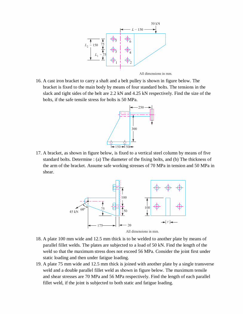
16. A cast iron bracket to carry a shaft and a belt pulley is shown in figure below. The
bracket is fixed to the main body by means of four standard bolts. The tensions in the
slack and tight sides of the belt are 2.2 kN and 4.25 kN respectively. Find the size of the
bolts, if the safe tensile stress for bolts is 50 MPa.
17. A bracket, as shown in figure below, is fixed to a vertical steel column by means of five
standard bolts. Determine : (a) The diameter of the fixing bolts, and (b) The thickness of
the arm of the bracket. Assume safe working stresses of 70 MPa in tension and 50 MPa in
shear.
18. A plate 100 mm wide and 12.5 mm thick is to be welded to another plate by means of
parallel fillet welds. The plates are subjected to a load of 50 kN. Find the length of the
weld so that the maximum stress does not exceed 56 MPa. Consider the joint first under
static loading and then under fatigue loading.
19. A plate 75 mm wide and 12.5 mm thick is joined with another plate by a single transverse
weld and a double parallel fillet weld as shown in figure below. The maximum tensile
and shear stresses are 70 MPa and 56 MPa respectively. Find the length of each parallel
fillet weld, if the joint is subjected to both static and fatigue loading.

20. Determine the length of the weld run for a plate of size 120 mm wide and 15 mm thick to
be welded to another plate by means of 1. A single transverse weld; and 2. Double
parallel fillet welds when the joint is subjected to variable loads.
21. A 200 × 150 × 10 mm angle is to be welded to a steel plate by fillet welds as shown in
Fig. 10.21. If the angle is subjected to a static load of 200 kN, find the length of weld at
the top and bottom. The allowable shear stress for static loading may be taken as 75 MPa.
22. A welded joint as shown in figure below, is subjected to an eccentric load of 2 kN. Find
the size of weld, if the maximum shear stress in the weld is 25 MPa.
23. A rectangular cross-section bar is welded to a support by means of fillet welds as shown
in figure below. Determine the size of the welds, if the permissible shear stress in the
weld is limited to 75 MPa.

24. A bracket carrying a load of 15 kN is to be welded as shown in figure below. Find the
size of weld required if the allowable shear stress is not to exceed 80 MPa.
25. A rectangular steel plate is welded as a cantilever to a vertical column and supports a
single concentrated load P, as shown in figure below. Determine the weld size if shear
stress in the same is not to exceed 140 MPa.
26. Find the maximum shear stress induced in the weld of 6 mm size when a channel, as
shown in figure below, is welded to a plate and loaded with 20 kN force at a distance of
200 mm.
27. The bracket, as shown in figure below, is designed to carry a dead weight of P = 15 kN.
What sizes of the fillet welds are required at the top and bottom of the bracket? Assume

the forces act through the points A and B. The welds are produced by shielded arc
welding process with a permissible strength of 150 MPa.
28. A bracket, as shown in figure below, carries a load of 10 kN. Find the size of the weld if
the allowable shear stress is not to exceed 80 MPa.
29. figure below shows a welded joint subjected to an eccentric load of 20 kN. The welding
is only on one side. Determine the uniform size of the weld on the entire length of two
legs. Take permissible shear stress for the weld material as 80 MPa.
30. A bracket is welded to the side of a column and carries a vertical load P, as shown in
figure below. Evaluate P so that the maximum shear stress in the 10 mm fillet welds is 80
MPa.

31. A double riveted lap joint is made between 15 mm thick plates. The rivet diameter and
pitch are 25 mm and 75 mm respectively. If the ultimate stresses are 400 MPa in tension,
320 MPa in shear and 640 MPa in crushing, find the minimum force per pitch which will
rupture the joint. If the above joint is subjected to a load such that the factor of safety is 4,
find out the actual stresses developed in the plates and the rivets.
32. Find the efficiency of the following riveted joints :
(i) Single riveted lap joint of 6 mm plates with 20 mm diameter rivets having a pitch of
50 mm. (ii) Double riveted lap joint of 6 mm plates with 20 mm diameter rivets having a
pitch of 65 mm.
Assume Permissible tensile stress in plate = 120 MPa; Permissible shearing stress in
rivets = 90 MPa; Permissible crushing stress in rivets = 180 MPa.
33. A double riveted double cover butt joint in plates 20 mm thick is made with 25 mm
diameter rivets at 100 mm pitch. The permissible stresses are : σt = 120 MPa; τ = 100
MPa; σc = 150 MPa Find the efficiency of joint, taking the strength of the rivet in double
shear as twice than that of single shear.
34. Design a double riveted butt joint with two cover plates for the longitudinal seam of a
boiler shell 1.5 m in diameter subjected to a steam pressure of 0.95 N/mm 2 . Assume
joint efficiency as 75%, allowable tensile stress in the plate 90 MPa ; compressive stress
140 MPa ; and shear stress in the rivet 56 MPa.
35. Design a lap joint for a mild steel flat tie-bar 200 mm × 10 mm thick, using 24 mm
diameter rivets. Assume allowable stresses in tension and compression of the plate
material as 112 MPa and 200 MPa respectively and shear stress of the rivets as 84 MPa.
Show the disposition of the rivets for maximum joint efficiency and determine the joint
efficiency. Take diameter of rivet hole as 25.5 mm for a 24 mm diameter rivet.
36. An eccentrically loaded lap riveted joint is to be designed for a steel bracket as shown in
figure below. The bracket plate is 25 mm thick. All rivets are to be of the same size. Load
on the bracket, P = 50 kN ; rivet spacing, C = 100 mm; load arm, e = 400 mm.
Permissible shear stress is 65 MPa and crushing stress is 120 MPa. Determine the size of
the rivets to be used for the joint.

37. The bracket as shown in figure below, is to carry a load of 45 kN. Determine the size of
the rivet if the shear stress is not to exceed 40 MPa. Assume all rivets of the same size.
38. A bracket is riveted to a column by 6 rivets of equal size as shown in figure below. It
carries a load of 60 kN at a distance of 200 mm from the centre of the column. If the
maximum shear stress in the rivet is limited to 150 MPa, determine the diameter of the
rivet.
39. A bracket is supported by means of 4 rivets of same size, as shown in figure below.
Determine the diameter of the rivet if the maximum shear stress is 140 MPa.

40. A bracket is riveted to a columm by 6 rivets of equal size as shown in figure below. It
carries a load of 100 kN at a distance of 250 mm from the column. If the maximum shear
stress in the rivet is limited to 63 MPa, find the diameter of the rivet.

Unit-IV : ENERGY STORING ELEMENTS AND ENGINE COMPONENTS
Various types of springs, optimization of helical springs - rubber springs - Flywheels considering
stresses in rims and arms for engines and punching machines- Connecting Rods and crank shafts.
1. Determine the combined stiffness of two springs connected in parallel and series.
(April/May 2019)
Springs in series:
y = y1 + y2
𝑦 =𝑃
𝑘, 𝑦1 =
𝑃
𝑘1 , 𝑦2 =
𝑃
𝑘2
𝑃
𝑘=
𝑃
𝑘1+
𝑃
𝑘2
1
𝑘=
1
𝑘1+
1
𝑘2
Where k is combined stiffness.
Springs in parallel:
P = P1 + P2
P = ky, P1 = k1y, P2 = k2y
ky = k1y + k2y
k = k1 + k2
Where k is combined stiffness.
2. Define spring rate. (May /June 2016)
The spring rate (or stiffness or spring constant) is defined as the force required to produce unit
deflection of the spring. Mathematically,
Spring rate, q = P / y
where P = Axial force(load), and y = Axial deflection of the spring.
3. State any two functions of springs. (Nov /Dec 2016) (i) To absorb shocks. (Eg: Vehicle suspension spring)
(ii) To store energy. (Eg: Clock)
(iii) To measure force. (Eg: Spring balance) (iv) To apply force and control motion. (Eg: Cam and follower)
4. What type of spring is used to maintain an effective contact between a cam and a reciprocating
roller follower or flat faced follower? (Nov /Dec 2015)
Helical compression spring with grounded and square ends is used to maintain an effective contact
between a cam and a reciprocating roller follower or flat faced follower.
5. While designing helical spring, K is introduced in the shear stress equation, why? (Nov /Dec
2018) (Nov /Dec 2017)
What is Wahl factor and why is it required? (May /June 2013)
While designing a helical spring in order to consider the effects of both direct shear as well as
curvature of the wire, Wahl’s stress factor (K) introduced by A.M. Wahl is used.
Refer PSG DB Pg No. 7.100 Here Ks is mentioned as K

6. What is nipping in leaf springs? (Nov /Dec 2018)
What is the objective of the nipping of the leaf spring? (May /June 2012)
The stress in the full length leaves is 50% greater than the stress in the graduated leaves. In order to
make all the leaves equally stressed, full length leaves are given greater radius of curvature than
graduated leaves. Hence a gap or clearance will be created between the leaves, before they are
assembled with central clip. This initial gap ‘h’ is called as nip and it is closed by giving initial
preload by tightening the central bolts. This method of pre-stressing the full length leaf is called as
nipping.
7. Define spring index. (May /June 2013)
The spring index is defined as the ratio of the mean diameter of the coil to the diameter of the wire.
Mathematically,
Spring index, C = D / d
where D = Mean diameter of the coil, and d = Diameter of the wire.
8. List out the materials commonly used for manufacture of the leaf spring. (Nov /Dec 2012)
According to Indian standards, the recommended materials are :
1. For automobiles : 50 Cr 1 V 23 and 55 Si 2 Mn 90 are used in hardened and tempered condition.
[PSG DB Pg. No. 1.17
2. For rail road springs : C 55 (water-hardened), C65 and C 75 (oil-hardened), 40 Si 2 Mn 90 (water-
hardened) and 55 Si 2 Mn 90 (oil-hardened).
9. Write the advantages of Belleville spring. (May /June 2012) (i) It is simple in construction and easy to manufacture.
(ii) It is very compact (small in size).
(iii) Very large force is produced for small deflection of the spring.
(iv) Number of individual cone disks of particular size can be used in parallel, series or parallel-series combination to produce variety of spring constants.
10. List the advantages of helical springs. (Nov /Dec 2013)
(i) Design is simple and easy to manufacture.
(ii) Comparatively cheaper. (iii) High reliability.
(iv) Deflection produces is linearly proportional to the applied force.
11. Distinguish between closed coiled and open coiled springs. (Nov /Dec 2014)
Closed coiled helical spring Open coiled helical spring
1. Spring wire is coiled so close. Helix angle is
very small. It is usually less than 10˚.
Spring wire is coiled in such a way, that there is
large gap between adjacent coils. Helix angle is large. It is usually greater than 10˚.
2. Widely used. They have only few application.
Eg. : Valve spring Eg. : Spring in shock absorbers.
12. What is meant by semi elliptical leaf springs? (May /June 2014)
A multi leaf spring consists of a series of flat plates, usually of semi-elliptical shape assembled
together by means of two U-bolts and a centre clip. The longest leaf at the top, called as master leaf is

bent at the both the ends to form the spring eyes. They are widely used in suspension system of cars,
trucks and railway wagons.
13. A helical spring of rate 12 N/mm is mounted on the top of another spring of rate 8 N/mm. Find
the force required to give a deflection of 50 mm. (Nov /Dec 2013)
k1= 12 N/mm; k2 = 8 N/mm
Springs are in series,
1
𝑘=
1
𝑘1+
1
𝑘2 =
1
𝑘=
1
12+
1
8 =
2 + 3
24 =
5
24
1
𝑘 =
5
24 => 𝑘 =
24
5 = 4.8 N/mm
P = k y = 4.8 × 50 = 240 N
14. Define surge in springs. (April/May 2019)
When the natural frequency of vibrations of spring coincides with the frequency of external periodic
force, acting on it, resonance occurs. In this state the spring is subjected to a wave of successive
compression of coils that travels from one end to the other end and it is reflected back. This
phenomenon is called as surge of spring. Surge is found in valve springs, which are subjected to
periodic force.
15. State functions of flywheel. (April/May 2019)
What is the purpose of the flywheel? (Nov /Dec 2015)
(i) To store and release energy when needed during the work cycle.
(ii) To reduce the power capacity of the electric motor or engine.
(iii) To reduce the amplitude of speed fluctuations.
16. What is the purpose of the flywheel that is used in an IC engine? (Nov /Dec 2013)
In I.C. engines, the energy is developed only during power stroke which is much more than the
engine load and no energy is being developed during other strokes (suction, compression and exhaust
strokes). The excess energy developed during power stroke is absorbed by the flywheel and it is
released to the crankshaft during other strokes when no energy is developed.
17. Brief why flywheels are used in punching machines. (Nov /Dec 2017)
In punching machines, maximum power is required only during a small part of the cycle, when actual
punching takes place. If this machine is directly driven by electric motor, a high capacity motor is
required. When flywheel is used, it stores energy supplied during idle part of cycle and releases it
during the actual punching operation and hence smaller capacity motor is sufficient. (When energy is
stored flywheel will be accelerated and slowed down when it is released)
18. How does the function of flywheel differ from that of governor? (Nov /Dec 2016)
In what aspect the flywheel differs from governor. (May /June 2013)
Flywheel is used to store excess energy produced during power stroke and release it during the other
strokes. Hence cyclic speed fluctuation in engine is avoided. Governor controls the supply of fuel and
maintains the mean speed of the engine.

19. Define the term ‘fluctuation of speed’ and ‘fluctuation of energy’. (May /June 2016) (May /June
2014)
The difference between the maximum and minimum speeds during a cycle is called the maximum
fluctuation of speed.
The variations of energy above and below the mean resisting torque line are called fluctuation of
energy. The difference between the maximum and the minimum energies is known as maximum
fluctuation of energy.
Maximum fluctuation of energy,∆ E = Maximum energy – Minimum energy
20. Define (a) Coefficient of fluctuation of speed (b) Coefficient of fluctuation of energy. (Nov /Dec
2014)
Coefficient of fluctuation of speed : The ratio of the maximum fluctuation of speed to the mean
speed is called coefficient of fluctuation of speed.
Ks = 𝑁1− 𝑁2
𝑁 =
ω1− ω2
ω
Where N1, N2, N are maximum, minimum and mean speeds respectively
ω 1, ω 2, ω are maximum, minimum and mean angular velocity respectively
Coefficient of fluctuation of energy : It is defined as the ratio of the maximum fluctuation of energy
to the work done per cycle. It is usually denoted by KE. Mathematically, coefficient of fluctuation of
energy,
KE = 𝑀𝑎𝑥𝑖𝑚𝑢𝑚 𝑓𝑙𝑢𝑐𝑡𝑢𝑎𝑡𝑖𝑜𝑛 𝑜𝑓 𝑒𝑛𝑒𝑟𝑔𝑦
𝑊𝑜𝑟𝑘 𝑑𝑜𝑛𝑒 𝑝𝑒𝑟 𝑐𝑦𝑐𝑙𝑒
21. Name the materials used for making fly wheels. (Nov /Dec 2013)
Traditionally flywheels are made of cast iron. Recently in modern car engines flywheels are made of
high strength steels and composites like Graphite-Fiber Reinforced Polymer(GFRP).
22. What are the various forces acting on a connecting rod? (April/May 2019)
The various forces acting on the connecting rod are as follows:
1. Force on the piston due to gas pressure and inertia of the reciprocating parts,
2. Force due to inertia of the connecting rod or inertia bending forces,
3. Force due to friction of the piston rings and of the piston, and
4. Force due to friction of the piston pin bearing and the crankpin bearing.
23. Define coefficient of steadiness. (Nov /Dec 2012)
The reciprocal of coefficient of fluctuation of speed is known as coefficient of steadiness and it is de-
noted by m.
m = 1
𝐾𝑆 =
𝑁
𝑁1− 𝑁2 =
ω
ω1− ω2
PART B
1. Design a closed coiled helical spring subjected a tensile load of magnitude varying from
2500N to 3000N and the axial deflection of spring for this range of load is 6.5 mm. Design the
spring, taking the spring index as 6 and safe shear stress for material equal to 465 MPa.

2. Design a CI flywheel for a four stroke engine developing 150 kW at 200 rpm. Calculate
the mean diameter of the flywheel if the hoop stress is not to exceed 4 MPa. Total fluctuation of
speed is to be 4 % of the mean speed. Work done during the power stroke may be assumed to be
1.5 times the average work done during the cycle. Density of CI is 7200 kg/m3.
3. Design a helical compression sprig to sustain an axial load of 4 kN. The deflection is 80
mm. Spring index is 6. The shear stress is not to exceed 350 MPa. Rigidity modulus for
spring material is 81 GPa.
4. Design a leaf spring for the following specifications for a truck. Assume FOS=2.
Maximum load on springs = 100 kN
No of springs = 4
Materrial of springs = Cr Va steel ( u=1380 MPa and E=206x103MPa) Span of spring = 1000
mm
Width of central band = 150 mm
Permissible deflection = 100 mm
Assume 2 full length leaves and 6 graduated leaves.
5. A vertical spring loaded valve is required for a compressed air receiver. The valve is to
start opening at a pressure of 1 N/mm 2 gauge and must be fully open with a lift of 4 mm at a
pressure of 1.2 N/mm2 gauge. The diameter of the port is 25 mm. Assume the allowable shear
stress in steel as 480 MPa and shear modulus as 80 kN/mm2.Design a suitable close coiled round
section helical spring having squared ground ends. Also specify initial compression and free
length of the spring.
6. A railway wagon weighing 50 kN and moving with a speed of 8 km per hour has to be
stopped by four buffer springs in which the maximum compression allowed is 220 mm. Find the
number of turns ineach spring of mean diameter 150 mm. The diameter of spring wire is 25 mm.
Take G = 84 kN/mm2.
7. A helical spring B is placed inside the coils of a second helical spring A, having the same
number of coils and free length. The springs are made of the same material. The composite
spring is compressed by an axial load of 2300 N which is shared between them. The mean
diameters of the spring A and B are 100 mm and 70 mm respectively and wire diameters are 13
mm and 8 mm respectively. Find the load taken and the maximum stress in each spring.
8. Design a concentric spring for an air craft engine valve to exert a maximum force of 5000
N under a deflection of 40 mm. Both the springs have same free length, solid length and are
subjected to equal maximum shear stress of 850 MPa. The spring index for both the springs is 6.

9. The free end of a torsional spring deflects through 90° when subjected to a torque of 4 N-
m. The spring index is 6. Determine the coil wire diameter and number of turns with the
following data :
Modulus of rigidity = 80 GPa ; Modulus of elasticity = 200 GPa; Allowable stress = 500 MPa.
10. A flat spiral steel spring is to give a maximum torque of 1500 N-mm for a maximum
stress of 1000 MPa. Find the thickness and length of the spring to give three complete turns of
motion, when the stress decreases from 1000 to zero. The width of the spring strip is 12 mm. The
Young’s modulus for the material of the strip is 200 kN/mm2.
11. A semi-elliptical spring has ten leaves in all, with the two full length leaves extending
625 mm. It is 62.5 mm wide and 6.25 mm thick. Design a helical spring with mean diameter of
coil 100 mm which will have approximately the same induced stress and deflection for any load.
The Young’s modulus for the material of the semi-elliptical spring may be taken as 200 kN/mm
2 and modulus of rigidity for the material of helical spring is 80 kN/mm 2 .
12. A carriage spring 800 mm long is required to carry a proof load of 5000 N at the centre.
The spring is made of plates 80 mm wide and 7.5 mm thick. If the maximum permissible stress
for the material of the plates is not to exceed 190 MPa, determine :
1. The number of plates required, 2. The deflection of the spring, and 3. The radius to which the
plates must be initially bent. The modulus of elasticity may be taken as 205 kN/mm2.
13. A semi-elliptical laminated spring 900 mm long and 55 mm wide is held together at the
centre by a band 50 mm wide. If the thickness of each leaf is 5 mm, find the number of leaves
required to carry a load of 4500 N. Assume a maximum working stress of 490 MPa.
If the two of these leaves extend the full length of the spring, find the deflection of the spring.
The
Young’s modulus for the spring material may be taken as 210 kN/mm2 .
14. A machine has to carry out punching operation at the rate of 10 holes/min. It does 6 N-m
of work per sq mm of the sheared area in cutting 25 mm diameter holes in 20 mm thick plates. A
flywheel is fitted to the machine shaft which is driven by a constant torque. The fluctuation of
speed is between 180 and 200 r.p.m. Actual punching takes 1.5 seconds. Frictional losses are
equivalent to 1/6 of the workdone during punching. Find:
(a) Power required to drive the punching machine, and
(b) Mass of the flywheel, if radius of gyration of the wheel is 450 mm.
15. A single cylinder internal combustion engine working on the four stroke cycle develops
75 kW at 360 r.p.m. The fluctuation of energy can be assumed to be 0.9 times the energy
developed per cycle. If the fluctuation of speed is not to exceed 1 per cent and the maximum
centrifugal stress in the flywheel is to be 5.5 MPa, estimate the mean diameter and the cross-
sectional area of the rim. The material of the rim has a density of 7200 kg / m 3 .

16. Design a cast iron flywheel for a four stroke cycle engine to develop 110 kW at 150
r.p.m. The work done in the power stroke is 1.3 times the average work done during the whole
cycle. Take the mean diameter of the flywheel as 3 metres. The total fluctuation of speed is
limited to 5 per cent of the mean speed. The material density is 7250 kg / m 3 . The permissible
shear stress for the shaft material is 40 MPa and flexural stress for the arms of the flywheel is 20
MPa.
17. A punching press is required to punch 40 mm diameter holes in a plate of 15 mm
thickness at the rate of 30 holes per minute. It requires 6 N-m of energy per mm 2 of sheared
area. Determine the moment of inertia of the flywheel if the punching takes one-tenth of a
second and the r.p.m. of the flywheel varies from 160 to 140.
18. A punch press is fitted with a flywheel capable of furnishing 3000 N-m of energy during
quarter of a revolution near the bottom dead centre while blanking a hole on sheet metal. The
maximum speed of the flywheel during the operation is 200 r.p.m. and the speed decreases by
10% during the cutting stroke. The mean radius of the rim is 900 mm. Calculate the approximate
mass of the flywheel rim assuming that it contributes 90% of the energy requirements.
19. A punching machine makes 24 working strokes per minute and is capable of punching 30
mm diameter holes in 20 mm thick steel plates having an ultimate shear strength of 350 MPa.
The punching operation takes place during 1/10th of a revolution of the crankshaft. Find the
power required for the driving motor, assuming a mechanical efficiency of 76%. Determine
suitable dimensions for the rim cross-section of the flywheel, which revolves at 9 times the speed
of crankshaft. The permissible coefficient of fluctuation of speed is 0.4.
The flywheel is to be made of cast iron having a safe tensile stress of 6 MPa and density 7250
kg/m3.
The diameter of the flywheel must not exceed 1.05 m owing to space restrictions. The hub and
spokesmay be assumed to provide 5% of the rotational inertia of the wheel. Check for the
centrifugal stress induced in the rim.
20. Design completely the flywheel, shaft and the key for securing the flywheel to the shaft,
for a punching machine having a capacity of producing 30 holes of 20 mm diameter per minute
in steel plate 16 mm thickness. The ultimate shear stress for the material of the plate is 360 MPa.
The actual punching operation estimated to last for a period of 36º rotation of the punching
machine crankshaft. This crank shaft is powered by a flywheel shaft through a reduction gearing
having a ratio 1 : 8. Assume that the mechanical efficiency of the punching machine is 80% and
during the actual punching operation the flywheel speed is reduced by a maximum of 10%. The
diameter of flywheel is restricted to 0.75 m due to space limitations.
21. A cast iron wheel of mean diameter 3 metre has six arms of elliptical section. The energy
to be stored in it is 560 kN-m when rotating at 120 r.p.m. The speed of the mean diameter is 18
m/s. Calculate the following:

(a)Assuming that the whole energy is stored in the rim, find the cross-section, if the width is 300
mm.
(b)Find the cross-section of the arms near the boss on the assumption that their resistance to
bending
is equal to the torsional resistance of the shaft which is 130 mm in diameter.
The maximum shear stress in the shaft is to be within 63 MPa and the tensile stress 16 MPa.
Assume
the minor axis of the ellipse to be 0.65 major axis.
22. A cast iron flywheel is to be designed for a single cylinder double acting steam engine
which delivers 150 kW at 80 r.p.m. The maximum fluctuation of energy per revolution is 10%.
The total fluctuation of the speed is 4 per cent of the mean speed. If the mean diameter of the
flywheel rim is 2.4 metres, determine the following :
(a) Cross-sectional dimensions of the rim, assuming that the hub and spokes provide 5% of the
rotational inertia of the wheel. The density of cast iron is 7200 kg/m 3 and tensile stress 16 MPa.
Take width of rim equal to twice of thickness.
(b) Dimensions of hub and rectangular sunk key. The shear stress for the material of shaft and
key is
40 MPa.
(c) Cross-sectional dimensions of the elliptical arms assuming major axis as twice of minor axis
and
number of arms equal to six.
23. Design a cast iron flywheel having six arms for a four stroke engine developing 120 kW
at 150 r.p.m. The mean diameter of the flywheel may be taken as 3 metres. The fluctuation of
speed is 2.5% of mean speed. The workdone during the working stroke is 1.3 times the average
workdone during the whole cycle. Assume allowable shear stress for the shaft and key as 40
MPa and tensile stress for cast iron as 20 MPa. The following proportions for the rim and
elliptical arms may be taken:
(a) Width of rim = 2 × Thickness of rim
(b) Major axis = 2 × Minor axis.
24. A four stroke oil engine developing 75 kW at 300 r.p.m is to have the total fluctuation of
speed limited to 5%. Two identical flywheels are to be designed. The workdone during the
power stroke is found to be 1.3 times the average workdone during the whole cycle. The turning
moment diagram can be approximated as a triangle during the power stroke. Assume that the
hoop stress in the flywheel and the bending stress in the arms should not exceed 25 MPa. The
shear stress in the key and shaft material should not exceed 40 MPa. Give a complete design of
the flywheel. Assume four arms of elliptical cross-section with the ratio of axes 1 : 2. Design
should necessarily include (i) moment of inertia of the flywheel, (ii) flywheel rim dimensions,
(iii) arm dimensions, and (iv) flywheel boss and key dimensions and sketch showing two views
of the flywheel with all the dimensions.

Unit-V : BEARINGS
Sliding contact and rolling contact bearings - Hydrodynamic journal bearings, Sommerfeld
Number, Raimondi and Boyd graphs - Selection of Rolling Contact bearings.
1. Differentiate sliding contact and rolling contact bearing. (April/May 2019) (May /June
2013)
Sliding contact bearing Rolling contact bearing
1. In sliding contact bearings, sliding takes place
along the surfaces of contact between the moving element and the fixed element.
In rolling contact bearings, the steel balls or
rollers, are interposed between the moving and fixed elements. The balls offer rolling
friction at two points for each ball or
roller.
2. They are also known as plain bearings, journal bearings or sleeve bearings.
They are also known as Anti friction bearings or ball bearings.
2. Define life of a bearing. (April/May 2019)
What is meant by life of anti-friction bearings? (Nov /Dec 2013)
The life of an individual ball (or roller) bearing may be defined as the number of revolutions (or hours
at some given constant speed) which the bearing runs before the first evidence of fatigue crack in
balls or races.
3. What is hydrostatic bearing?
The hydrostatic bearings are those which can support steady loads without any relative motion
between the journal and the bearing. This is achieved by forcing externally pressurized lubricant
between the members.
4. List the advantages of the hydrostatic bearings. (Nov /Dec 2018) (Nov /Dec 2017)
(i) High load carrying capacity even at low speeds. (ii) No starting friction.
(iii) No rubbing action at any operating speed or load.
5. Give two applications where the inner race is rotating and outer race is stationary in rolling
contact bearings. (Nov /Dec 2018)
In most of the applications the inner race rotates and the outer race is fixed in the housing.
Eg: Machine tool spindle, rope sheaves, hoisting drums, small size electric motor and gear boxes.
6. Give two applications where the inner race is stationary and outer race is rotating in rolling
contact bearings.

In front axles of automobile, the outer race rotates along with the wheel and the inner race is fixed in
the axle using interference fit. Similarly in pulley mounted on fixed axles the outer race rotates along
with the pulley and the inner race is fixed in the axle.
7. What are essential conditions for a wedge film formation in Hydro dynamic bearing?
(April/May 2019)
In hydrodynamic bearing, what are factors which influence the formation of wedge fluid film?
(Nov /Dec 2014)
(i) The operating speed should be sufficient such that continuous fluid film is established.
(ii) The bearing should be supplied with sufficient lubricant. (iii) The pressure developed should be greater than the critical pressure.
(iv) The fluid viscosity must be high to maintain sufficient film thickness.
(v) The contact surfaces of bearings and journals must be smooth.
8. Define load factor and explain its significance in related to bearing selection. (April/May 2019)
The forces acting on the bearing are calculated by considering the equilibrium of forces in horizontal
and vertical planes and hence the effect of dynamic load is not considered. In order to determine the
dynamic load carrying capacity of the bearings these forces are multiplied by a load factor. Load
factors are used in applications involving gear, chain and belt drives.
9. What type of bearing can take axial load? (Nov /Dec 2017)
Axial load is supported by thrust bearings.
Rolling contact bearings that supports axial load are:
(i) Taper roller bearing (ii) Thrust ball bearing
Sliding contact bearings that supports axial load are:
(i) Foot step bearing (ii) Collar bearing
10. Classify the types of bearings. (Nov /Dec 2016) (May /June 2014) 1. Depending upon the direction of load to be supported.
(i) Radial bearing (ii) Thrust bearings
2. Depending upon the nature of contact. (i) Sliding contact bearing (ii) Rolling contact bearings
11. Define the term Reliability of a bearing. (Nov /Dec 2016)
The reliability (R) is defined as the ratio of the number of bearings which have successfully
completed L million revolutions to the total number of bearings under test. Sometimes, it becomes
necessary to select a bearing having a reliability of more than 90%.
12. What is meant by hydrodynamic lubrication? (May /June 2016) (Nov /Dec 2012)
Hydrodynamic lubrication is defined as a system of lubrication in which the load-supporting fluid
film is created by the shape and relative motion of the sliding surfaces.
13. What are the advantages of Rolling Contact Bearings over Sliding Contact Bearings? (May
/June 2016)
1. Low starting and running friction except at very high speeds.
2. Ability to withstand momentary shock loads.
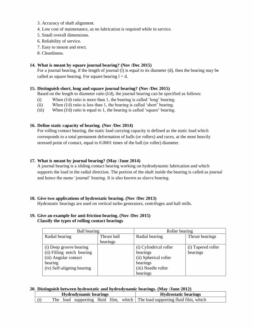
3. Accuracy of shaft alignment.
4. Low cost of maintenance, as no lubrication is required while in service.
5. Small overall dimensions.
6. Reliability of service.
7. Easy to mount and erect.
8. Cleanliness.
14. What is meant by square journal bearing? (Nov /Dec 2015)
For a journal bearing, if the length of journal (l) is equal to its diameter (d), then the bearing may be
called as square bearing. For square bearing l = d.
15. Distinguish short, long and square journal bearing? (Nov /Dec 2015)
Based on the length to diameter ratio (l/d), the journal bearing can be specified as follows:
(i) When (l/d) ratio is more than 1, the bearing is called ‘long’ bearing.
(ii) When (l/d) ratio is less than 1, the bearing is called ‘short’ bearing. (iii) When (l/d) ratio is equal to 1, the bearing is called ‘square’ bearing.
16. Define static capacity of bearing. (Nov /Dec 2014)
For rolling contact bearing, the static load carrying capacity is defined as the static load which
corresponds to a total permanent deformation of balls (or rollers) and races, at the most heavily
stressed point of contact, equal to 0.0001 times of the ball (or roller) diameter.
17. What is meant by journal bearing? (May /June 2014)
A journal bearing is a sliding contact bearing working on hydrodynamic lubrication and which
supports the load in the radial direction. The portion of the shaft inside the bearing is called as journal
and hence the name ‘journal’ bearing. It is also known as sleeve bearing.
18. Give two applications of hydrostatic bearing. (Nov /Dec 2013)
Hydrostatic bearings are used on vertical turbo generators, centrifuges and ball mills.
19. Give an example for anti-friction bearing. (Nov /Dec 2015)
Classify the types of rolling contact bearings
Ball bearing Roller bearing
Radial bearing Thrust ball
bearings
Radial bearing Thrust bearings
(i) Deep groove bearing
(ii) Filling notch bearing (iii) Angular contact
bearing
(iv) Self-aligning bearing
(i) Cylindrical roller
bearings (ii) Spherical roller
bearings
(iii) Needle roller bearings
(i) Tapered roller
bearings
20. Distinguish between hydrostatic and hydrodynamic bearings. (May /June 2012)
Hydrodynamic bearings Hydrostatic bearings
(i) The load supporting fluid film, which The load supporting fluid film, which

separates the two surfaces, is created by the
shape and relative motion of sliding surface.
separates the two surfaces, is created by an
external source, like pump supplying lubricant under pressure.
(ii) Initially there will be metal to metal contact
hence there will be starting friction.
No starting friction.
(iii) Friction will be more at lower speeds. At any operating speed or load friction is low and constant.
(iv) Simple in construction, low initial and
maintenance cost.
It is costlier than the hydrodynamic bearings.
21. What are anti friction bearings? (April/May 2017)
For starting condition and at moderate speeds the frictional loses in the rolling contact bearing are lower
than the sliding contact bearing. This is because the sliding contact is replaced by rolling contact resulting
in low coefficient of friction. Therefore rolling contact bearings are also called as anti-friction bearing
PART B
Unit-V : BEARINGS
1. Design a journal bearing for a centrifugal pump from the following data :
Load on the journal = 20 000 N; Speed of the journal = 900 r.p.m.;
Type of oil is SAE 10, for which the absolute viscosity at 55°C = 0.017 kg / m-s;
Ambient temperature of oil = 15.5°C ;
Maximum bearing pressure for the pump = 1.5 N / mm2 .
Calculate also mass of the lubricating oil required for artificial cooling, if rise of
temperature of oil be limited to 10°C. Heat dissipation coefficient = 1232 W/m2 /°C.
2. The load on the journal bearing is 150 kN due to turbine shaft of 300 mm diameter
running at 1800 r.p.m. Determine the following : 1. Length of the bearing if the allowable
bearing pressure is 1.6 N/mm2 , and 2. Amount of heat to be removed by the
lubricant per minute if the bearing temperature is 60°C and viscosity of the oil at
60°C is 0.02 kg/m-s and the bearing clearance is 0.25 mm.
3. A full journal bearing of 50 mm diameter and 100 mm long has a bearing pressure of 1.4
N/mm 2 . The speed of the journal is 900 r.p.m. and the ratio of journal diameter to the
diametral clearance is 1000. The bearing is lubricated with oil whose absolute viscosity at
the operating temperature of 75°C may be taken as 0.011 kg/m-s. The room temperature
is 35°C. Find : 1. The amount of artificial cooling required, and 2. The mass of the
lubricating oil required, if the difference between the outlet and inlet temperature of the
oil is 10°C. Take specific heat of the oil as 1850 J / kg / °C.
4. A 150 mm diameter shaft supporting a load of 10 kN has a speed of 1500 r.p.m. The shaft
runs in a bearing whose length is 1.5 times the shaft diameter. If the diametral clearance
of the bearing is 0.15 mm and the absolute viscosity of the oil at the operating
temperature is 0.011 kg/m-s, find the power wasted in friction.

5. A 80 mm long journal bearing supports a load of 2800 N on a 50 mm diameter shaft. The
bearing has a radial clearance of 0.05 mm and the viscosity of the oil is 0.021 kg / m-s at
the operating temperature. If the bearing is capable of dissipating 80 J/s, determine the
maximum safe speed.
6. The main bearing of a steam engine is 100 mm in diameter and 175 mm long. The
bearing supports a load of 28 kN at 250 r.p.m. If the ratio of the diametral clearance to
the diameter is 0.001 and the absolute viscosity of the lubricating oil is 0.015 kg/m-s, find
: 1. The coefficient of friction ; and 2.The heat generated at the bearing due to friction.
7. A journal bearing is proposed for a steam engine. The load on the journal is 3 kN,
diameter 50 mm, length 75 mm, speed 1600 r.p.m., diametral clearance 0.001 mm,
ambient temperature 15.5°C. Oil SAE 10 is used and the film temperature is 60°C.
Determine the heat generated and heat dissipated. Take absolute viscosity of SAE10 at
60°C = 0.014 kg/m-s.
8. A tentative design of a journal bearing results in a diameter of 75 mm and a length of 125
mm for supporting a load of 20 kN. The shaft runs at 1000 r.p.m. The bearing surface
temperature is not to exceed 75°C in a room temperature of 35°C. The oil used has an
absolute viscosity of 0.01 kg/m-s at the operating temperature. Determine the amount of
artificial cooling required in watts. Assume d/c = 1000.
9. A journal bearing is to be designed for a centrifugal pump for the following data : Load
on the journal = 12 kN ; Diameter of the journal = 75 mm ; Speed = 1440 r.p.m ;
Atmospheric temperature of the oil = 16°C ; Operating temperature of the oil = 60°C;
Absolute viscosity of oil at 60°C = 0.023 kg/m-s. Give a systematic design of the bearing.
10. Design a journal bearing for a centrifugal pump running at 1440 r.p.m. The diameter of
the journal is 100 mm and load on each bearing is 20 kN. The factor ZN/p may be taken
as 28 for centrifugal pump bearings. The bearing is running at 75°C temperature and the
atmosphere temperaturic is 30°C. The energy dissipation coefficient is 875 W/m 2 /°C.
Take diametral clearance as 0.1 mm.
11. A journal bearing with a diameter of 200 mm and length 150 mm carries a load of 20 kN,
when the journal speed is 150 r.p.m. The diametral clearance ratio is 0.0015. If possible,
the bearing is to operate at 35°C ambient temperature without external cooling with a
maximum oil temperature of 90°C. If external cooling is required, it is to be as little as
possible to minimise the required oil flow rate and heat exchanger size.
1. What type of oil do you recommend ?
2. Will the bearing operate without external cooling?
3. If the bearing operates without external cooling, determine the operating oil
temperature?

4. If the bearing operates with external cooling, determine the amount of oil in kg/min
required to carry away the excess heat generated over heat dissipated, when the oil
temperature rises from 85°C to 90°C, when passing through the bearing.
12. A shaft rotating at constant speed is subjected to variable load. The bearings supporting
the shaft are subjected to stationary equivalent radial load of 3 kN for 10 per cent of time,
2 kN for 20 per cent of time, 1 kN for 30 per cent of time and no load for remaining time
of cycle. If the total life expected for the bearing is 20 × 106 revolutions at 95 per cent
reliability, calculate dynamic load rating of the ball bearing.
13. The rolling contact ball bearing are to be selected to support the overhung countershaft.
The shaft speed is 720 r.p.m. The bearings are to have 99% reliability corresponding to a
life of 24 000 hours. The bearing is subjected to an equivalent radial load of 1 kN.
Consider life adjustment factors for operating condition and material as 0.9 and 0.85
respectively. Find the basic dynamic load rating of the bearing from manufacturer's
catalogue, specified at 90% reliability.
14. Select a single row deep groove ball bearing for a radial load of 4000 N and an axial load
of 5000 N, operating at a speed of 1600 r.p.m. for an average life of 5 years at 10 hours
per day. Assume uniform and steady load.
15. A single row angular contact ball bearing number 310 is used for an axial flow
compressor. The bearing is to carry a radial load of 2500 N and an axial or thrust load of
1500 N. Assuming light shock load, determine the rating life of the bearing.
16. Select a single row deep groove ball bearing with the operating cycle listed below, which
will have a life of 15 000 hours.
Fraction
of cycle
Type of load Radial
(N)
Thrust
(N)
Speed
(R.P.M.)
Service
factor
1/10 Heavy shocks 2000 1200 400 3.0
1/10 Light shocks 1500 1000 500 1.5
1/5 Moderate shocks 1000 1500 600 2.0
3/5 No shock 1200 2000 800 1.0
Assume radial and axial load factors to be 1.0 and 1.5 respectively and inner race rotates.
17. The ball bearings are to be selected for an application in which the radial load is 2000 N
during 90 per cent of the time and 8000 N during the remaining 10 per cent. The shaft is
to rotate at 150 r.p.m. Determine the minimum value of the basic dynamic load rating for
5000 hours of operation with not more than 10 per cent failures.
18. A ball bearing subjected to a radial load of 5 kN is expected to have a life of 8000 hours
at 1450 r.p.m. with a reliability of 99%. Calculate the dynamic load capacity of the

bearing so that it can be selected from the manufacturer's catalogue based on a reliability
of 90%.
19. A ball bearing subjected to a radial load of 4000 N is expected to have a satisfactory life
of 12 000 hours at 720 r.p.m. with a reliability of 95%. Calculate the dynamic load
carrying capacity of the bearing, so that it can be selected from manufacturer's catalogue
based on 90% reliability. If there are four such bearings each with a reliability of 95% in
a system, what is the reliability of the complete system?
20. A rolling contact bearing is subjected to the following work cycle :
(a) Radial load of 6000 N at 150 r.p.m. for 25% of the time; (b) Radial load of 7500 N at
600 r.p.m. for 20% of the time; and (c) Radial load of 2000 N at 300 r.p.m. for 55% of
the time. The inner ring rotates and loads are steady. Select a bearing for an expected
average life of 2500 hours.
21. A single row deep groove ball bearing operating at 2000 r.p.m. is acted by a 10 kN radial
load and 8 kN thrust load. The bearing is subjected to a light shock load and the outer
ring is rotating. Determine the rating life of the bearing.
22. A ball bearing operates on the following work cycle :
Element No. Radial load (N) Speed (R.P.M.) Element time (%)
1 3000 720 30
2 7000 1440 40
3 5000 900 30
The dynamic load capacity of the bearing is 16 600 N. Calculate 1. the average speed of rotation
; 2. the equivalent radial load and 3. the bearing life.


![Honeywell Pressure SwitchesHoneywell Pressure Switches High Pressure: HP Series, HE Series Factory set 150 psi to 4500 psi [10,34 bar to 310,26 bar] Low Pressure: LP Series, LE Series](https://img.dokumen.tips/doc/110x75/60ad806272620b5c0e1b1975/honeywell-pressure-switches-honeywell-pressure-switches-high-pressure-hp-series.jpg)


![Honeywell Pressure Switches · 2016-04-30 · Honeywell Pressure Switches High Pressure: HP Series, HE Series Factory set 150 psi to 4500 psi [10,34 bar to 310,26 bar] Low Pressure:](https://img.dokumen.tips/doc/110x75/5f842218cd8bc44621178411/honeywell-pressure-2016-04-30-honeywell-pressure-switches-high-pressure-hp-series.jpg)