Embed Size (px)
Citation preview

RADIO CONSTRUCTOR
:
BOOKS FOR THE TV ENTHUSIAST
"... A book that should be in every television dealers service workshop, and in every home- constructor's, for that matter."
Journal of the Television Society
"... The book will undoubtedly be of value to TV service engine- ers, particularly those who are not fully experienced in translating the appearance of faulty pictures into the necessary adjustments or receiver fault location."
Wireless and Electrical Trader
Lavishly illustrated by photographs taken from the screen of a tele- visor exhibiting the faults under discussion.
80 pages, size 8i" x 5i"
Price 5s. Postage 3d.
Edited by John Cura and Leonard Stanley, and illustrated with 150 "Tele-Snaps," this book caters for both the home viewer, and the more advanced constructor. We regard both these books as complementary, and have no hes- itation in recommending them to all television servicemen and con- structors.
68 pages, size 7i" x 5"
Price 3s. 6d. Postage 2d.
Both books available from your usual supplier, or direct (Trade enquiries invited)
DATA PUBLICATIONS
57 Maida Vale London W9
Published by Data Publications Ltd. 57 Maida Vale Paddington London W9 Printed by A. Quick and Company Limited Oxford House Clacton-on-Sea Essex
xuea
IHG
m
I
m i
rtoftantit
THltVlSlON
mm
SERVICE
»
Volume 6 Number 12
AUGUST
1953
ADOG'
JGDSffBOQWDB
for the Radio and Television Enthusiast
DENCO O/PCOU. RJ BLUE I
□ □ □ □ mi
M
■ 1
#Ct
$
it"
itV tv*4
m *4
a £7
ft
m m i o o m
POIKTS MARKED E ARE 4 B A. SOLDER TAGS < TAp BOARD POINTS MARKED A ARE A B.A. SOLDER TACS IIMPFRSIDE OF CHASSIS LAYOUT
ALSO IN THIS ISSUE
The "UNIVERSAL" Large Screen AC/DC Televisor
INTERCOM AMPLIFIER AC TRF DOMESTIC RECEIVER IMPROVED FRAME TIMEBASE AMPLIFIER FOR THE VCR97 RF EHT OSCILLATORS TRANSISTORS TUNING METER OSCILLOSCOPE TRACES No. 2 • RADIO CONTROL EQUIPMENT
etc. etc.
www.americanradiohistory.com

RADIO CONSTRUCTOR
THE MODERN BOOK CO.
The Radio Amateur's Handbook by A.R.R.L. 1953. 30s Od. Postage IsOd.
Television Fault Finding compiled by Radio Constructor. 5s Od. Postage 6d.
Receivers, Pre-Selectors and Con- verters. 2s 6d. Postage 2d.
The Oscilloscope Book by E. N. Bradley 5s Od. Postage 3d.
Reference Data for Radio Engineers. STC. 10s 6d. Postage 6d.
Television Receiver Design I by A. Uitjens. 21s Od. Postage 9d.
Amplifiers by G. A. Briggs and H. H. Garner. ISs. 6d. Postage 6d.
Radio Servicing Instrument by E. N. Bradley. 4s 6d. Postage 3d.
Constructors' Radio Receivers by E. N. Bradley. 2s 6d. Postage 2d.
Brimar Radio and Teletube Manual No. 5. Ss Od. Postage 6d.
Radio Valve Data compiled by Wire- less World. 3s 6d. Postage 3d.
P. H. Brans' Equivalent Radio Tube Vade-Mecum 1953. 21s Od. Postage I s Od.
Basic Mathematics for Radio Stu- dents by F. M. Colebrook. 10s 6d. Postage 6d.
Foundations of Wireless by M. G. Scroggie. 12s 6d. Postage 9d.
We have the finest selection of British and American Radio publications in the Country. Complete list on application.
19-23 PRAED STREET (Dept. RC) LONDON W2 PADdington 4185
SCOTTISH INSURANCE
CORPORATION LTD.
62-63 CHEAPSIDE
LONDON, E.C.2.
TE':fV!SlcON SETS AND SHORT WAVE TRANSMITTERS
Ho,, JtfjM10" and Shorf,Wave Transmitters/Receivers are expensive to acquire and you no ' ^ y-pnze IOUr lnstal'atl0"- APart from the value of your Set, you might be held respon- sible should injury be caused by a fault in the Set, or injury or damage by your Aerial collansing
proves Te,eViSi0n SetS and Sh°rt ^a ve Transmitters / Receivers Loss or damage to installation (including in the case of Television Sets the Cathode Ray
dwethng^house'. P SIOn' L|ghtning' Theft 0r Accidental External Means at any private (fc) (i) Legal Liability for bodily injury to Third Parties or damage to their property arising
ou*. c breakage or collapse of the Aerial Fittings or Mast, or through any defect in the Set. Indemnity £10,000 any one accident. (//) Damage to your property or that of your landlord arising out of the breakage or
collapse of the Aerial Fittings or Mast, but not exceeding £500 0f ?OVer (0) iS 5/T a ^ for Sets worth £50 or less' and for Sets valued at more
cover (a) oerC5/- 1? takeTab^0"' ^ ^ ^ ("') COStS 0nly ^ ^ ^ with
VER^LO\rcOSTP|NVOWFnAN!f INSU^E y0"1", installation-it is well worth while AT THE OffW-I TVL k INN(OLVED. If you will complete and return this form to the Corporation's 0* 5 f ? address, a proposal will be submitted for completion. NAME {Block Letters) (If Lady, state Mrs. or Miss) 1111 II ADDRESS (Block Letters)
v ll 11 il B i III
RADIO CONSTRUCTOR 609
POSITIVELY
the most EFFICIENT
for H.T. SUPPLIES
to radio and television receivers and without a doubt the most reliable. Constant development of Westinghouse rectifiers to produce units capable of meeting all demands in this particular field has resulted in a decrease in size while maintaining the same
output. More recent designs have produced units to supersede those in current ranges of commercial and home constructed television receivers, and although physically they are of the same dimensions the current output has been considerably increased
STIIWTE
METAL RECTIFIERS
IVrite in for further details. A copy of "THE ALL METAL WAY" can be obtained by sending 6d. in stamps to .
WESTINGHOUSE BRAKE & SIGNAL COMPANY LIMITED, 82 YORK WAY, KINGS CROSS, LONDON. Nl
www.americanradiohistory.com

610 RADIO CONSTRUCTOR
WIDE ANGLE TV
of
Allen, Denco, Colvern Dubilier, Elac, McMurdo, Morgan
STC, TCC for the
"TELEKING" "VIEWMASTER" CONVERSION and "MAGNA VIEW"
{Radio Constructor) also
TUBES, VALVES & CABINETS etc. Price Lists on receipt of SAE
H. L. SMITH & CO. LTD. 287/9 Edgware Road London W2
Telephone Paddington 5891 Hours 9 till 6 (Thursday I o'clock)
Nr. Edgware Road Stations, Metropolitan & Bakerloo
ARTHURS HAVE ITJ LONDON'S OLDEST RADIO DEALERS
LARGE VALVE STOCKS AVOMETERS IN STOCK
AVandTTeaylor M^err" Generators LeUnits0int 0,16 Amp'i,!ers and Tuning Chapman Tuning Units. Crystal and Moving Coil Mies. Decca Replacement Heads and Pickups, Goodman's Axiom ISO Speakers. Partridge Output Transformers for William-
son Amplifier. All Components for the Radio Constructor's
16" Televisor. Weare & Wright Tape Deck £35.
LATEST VALVE MANUALS Mullard, Osram & Brimar No. 4 5/- each Mazda 2/- each Postage 6d. extra
TELEVISION SETS, WIRE AND TAPE RECORDERS ALWAYS IN STOCK
Goods offered subject to price alterations and being unsold.
Arthurs JS PROP: ARTHUR GRAY LTD.
OUR ONLY ADDRESS: Gray House 150-52 Charing Cross Road
London, W.C.2. TEMpIe Bar 5833/4 and 4765 WRITE FOR LISTS
For
SUCCESSFUL
wide-angle
scanning
ALLEN DEFLECTOR COILS 70° Scan with minimum deflection defocusing High-efficiency castellated "FERROXCUBE" core. Suits any wide angle C.R.T. up to 27" double (d) Scan. LARGE SCREEN TELEVISION Can only be achieved by using high efficiency components throughout. ALLEN can supply the complete range. For prices and details of For circuit diagram of the full range of ALLEN ^ components—Write to addressed envelope to
ALLEN COMPONENTS LIMITED
Crown Works, 197 Lower Richmond Rd Richmond Surrey Telephone Prospect 9013
TELEVISION
CABINETS All Sizes up to 16' Tube
Specially Designed for 'Radio Con- structor' Set, and Illustrated on the
September Front Cover
Price £18:10 Carriage £1
SEND FOR ILLUSTRATED LEAFLET
H. ASHDOWN
98 HERTFORD ROAD TOT 2621 EDMONTON N9
RADIO CONSTRUCTOR 611
Your set
deserves a
Mullard
PIE
TV TUBE
If you nre building a television receiver, leave notbing to cbance; choose a Mullard Tube. Mullard Television Tubes owe their high reputation for performance, relia- bility and LONG LIFE to the unrivalled facibties for research possessed by Mullard; to the com- plete control of manufacture from the production of raw mate- rialstothecompletedproduct; i and, in particular, to the ion- M trap, which safeguards the Mj screen from damage by heavy JH negative ions produced in the ■■ region of the cathode. ™
^ .•ZSS'* -s J-* r witb,t9 a. ithiiversa . . ctaoSu-
!s&:—
VV/V,,;::;:.,
Mullard! MULLARD LTD • CENTURY HOUSE • SHAFTESBURY AVENUE LONDON ■ W.C.: MVM22
www.americanradiohistory.com

612 RADIO CONSTRUCTOR
CONDENSERS The abbreviated ranges of two popular types given here are representative of the wide variety of T.C.C. Condensers
available
' MICROPACK ' (Regd.) ELECTROLYTICS All Aluminium Construction
Cap. fxF. Wkg. Dimensions
Type Length Dia. 100 6 Ifin, Jin. CE32A 50 25 1 Jin. Jin. CEI8C 32 150 2Jin. 1 in. CEI9F
2 200 1 Jin. Jin. CE3IG 8 450 2Jin. 1 in. CEI9P
' PICOPACK (Regd.) MINIATURE ELECTROLYTICS (Plain Foil)
Capacity Peak Wkg. Dimensions Type p.F. Volts Body L'gth Dia. No.
8 6 l-iVm. .25in. CE72A 20 12 1 Jin. .34in. CE30B 30 15 1 Jin. .43in. CE7IB 10 25 1 Jin. .34in. CE30C 5 50 1 Jin. .34in. CE30D 2 150 1 Jin. .34in, CE30G
1 350 1 Jin. .34in. CE30N
THE TELEGRAPH CONDENSER Co Ltd Radio Division: North Acton, London, W3 Tel: Acorn 0061
._i
%
DATA BO OK
H 111!
1.: IliJ 32® ,
2'«
Just published — Data Book No. 7
"Jtfwirvrs.
Pre-Selectors
& Converters?9
The book for which you have been waiting! Containing complete constructional details of:
S.W. Mains Receiver . Portable Superhet TV Sound Receiver . TRF Receiver 13-31 Mcs Pre-selector . TV Pre-amplifier Regenerative Pre-selector . High Gain 10 Metre Converter . 2 Metre Converter
PRICE 2/6 Postage 2d Available immediately from:
Data Publications Ltd. 57 Maida Vale London W.9
RADIO CONSTRUCTOR 613
HOME EXPERIMENTAL KITS NOW AVAILABLE Practical experimen- tal kits form part of the following courses: Radio & Electronics, Draughtsmanship, Carpentry, Chem- istry, Photography and Commercial Art.
THIS
FULLY
INFOIIMATIVE
BROCHURE
describing the wide range of Engineering and Commercial Courses of modern training offered by E.M.I. Institutes — the only Postal College which is part of a world-wide Industrial Organisation.
Over 150 courses include:
General Radio & TV Engineering Radio & TV Servicing Radar Sound Recording & Reproduction Industrial Electronics Advanced Radio P.M.G. Certificate
Also Examination Courses for
Radio Amateurs Licence General Electrical Engineering Installations & Wiring I.E.E. Theory High Frequency Electronics Radio Operating ,.. and many others.
General Certificate of Education, O.Sc. Eng., Common Preliminary, A.M.I.Mech.E., A.M.I.C.E., A.M.I.Struct.E., A.M.Brit.l.R.E., A.F.R.Ae.S,, A.M.l.P.E,, A.M.I.I.A., A.M.I.MX, A.M.I,H. & V.E., M.R.Sanl, A.M.I.San.E,, A.M.I,Munic.E., A.M.l.E.D., A.M.ST., L.I.O.E, Also CITY and GUILDS Certificates in Mechanical, Electrical, Aeronautical, Automobile, Telecommunica- tions and Structural Engineering; Refrigeration, Heating & Ventilation, Courses also provided for all branches of Commerce and Business Management.
COURSES FROM £1 PER MONTH f -POST NOW-
Please send, without obligation, the above FREE book
INSTITUTES
E.M.I. Institutes, Dept. I79l<, I 43 Grove Park Road, Chiswick, London,W.4.
associated with
I NOTB ...V,
! Address..
MARP0NIPH0NE COLUMBIA & H.M.V
(His Master's Voice, etc.)
www.americanradiohistory.com

614 RADIO CONSTRUCTOR
COMPONENTS "INEXPENSIVE
CAR RADIO" Described in this Issue
each 20 s.w.g. Steel Case finished in Black Cellulose complete with Front and Rear Panels, Screen and Potentiometer Mounting Bracket. . . . 30/- DTB.6 — Constructor's Envelope giving full Assem- bly and Wiring Diagrams. . 2/6 Dual Purpose Coils: Range 2 Blue, Range 2 Yellow and Range 2 Red 3/11
I.F. Transformer, IFT.11. . 6/- Potentiometer, .5 M ohm. . 3/6
each Variable Condenser, 300 pF. 3 Gang 18/3 Concentric Trimmers, 3/30 pF 3/6 Valveholders, Octal, B7G, B9A I /- Slow Motion Epicyclic Drive 3/9 Lampholder 6d Knobs 8d Single Tag Posts .... 2d Extension Spindle and Coupling. ....... 2/- Scale, Medium Wave. . . 1/9
DENCO (CLACTON) LIMITED
357-9 OLD ROAD CLACTON-ON-SEA ESSEX
SURE tooetitat
aMiilMiHiiifiM
CAR RADIO
THE "INEXPENSIVE" CAR RADIO
RECEIVER DESCRIBED AND
ILLUSTRATED IN THIS ISSUE CAN BE COMPLETELY BUILT INCLUDING VIBRATOR PACK for X | 1 I O gt THIS PRICE INCLUDES ALL VALVES, 5-INCH SPEAKER, DRILLED CHASSIS, AND ALL COMPONENTS DOWN TO THE LAST NUT AND BOLT
SEND 2/8 for the complete Set of Assembly Instructions, CIRCUITS, LAYOUTS. POINT-TO-POINT DIAGRAMS, together with the complete Component Price List
This is NOT AN EX-GOVT. RECEIVER, it is a new design employing new Components and Valves
A GENUINE SPECIAL OFFER! PLESSEY 3 SPEED AUTO CHANGE UNITS £11-3-6 % These units will auto-change on all three
speeds, 7/n 10/n and 12/n. 0 They play MIXED 10/n and 12/n records. A bulk purchase NEW UNITS at enables us to offer these BRAND
this exceptional price. Please add 7/6 packing,
STERN RADIO LTD.
(NORMAL PRICE OVER £ 2 0) 0 They have separate sapphires for L.P. and
78 r.p.m., which are moved into position by a simple switch.
0 Minimum baseboard size required 16/n x 12^/n with height above 5?in and height below baseboard 2jin.
carriage and insurance. 109 & 115 FLEET STREET LONDON E.C.4.
Telephone CENTRAL 5812-3-4
The
RADIO Constructor
Vol. 6. No. 12. Annual Subscription 18/- August I9S3 Editorial and Advertising Offices—57 Maida Vale London W9
Telephone CUNingham 6518 Editor: C. W. C. OVERLAND, G2ATV Advertising Manager: F. A. BALDWIN
CONTENTS
Suggested Circuits: Frequency Changer as Source of Negative Bias, by G. A. French .616
In Your Workshop — An Intercom Amplifier, by J. R. D. . .618 Valves and Their Power Supplies, Part 9, by F. L. Bayliss, A.M.I.E.T. 621 Test Card "C" 624 Radio Control Equipment, Part 6, by Raymond F. Stock . . . 625 The " Inexpensive " — A Cheap and Efficient Car Radio, by A. Tiel. 628 The " Universal " Large Screen AC/DC Televisor, Part 3, described
by A. S. Torrance, A.M.I.P.R.E., A.M.T.S 636 Radio Miscellany, by Centre Tap 644 Query Corner — An Improved Frame Timebase Amplifier for the
VCR97 646 Oscilloscope Traces, No. 2, by A. B. . 648 Transistors — The Crystal Comes Back Again, by T. W. Dresser . 649 AC TRF Domestic Receiver, by James S. Kent 652 A Tuning Meter, by C. B. Raithby, G8GI 654 Trade Review 656
NOTICES THE CONTENTS of this magazine are strictly copyright and may not be reproduced without obtaining prior permission from the Editor. Opinions expressed by contributors are not necessarily those of the Editor or proprietors.
THE EDITOR invites original contributions on con- struction of radio subjects. All material used will be paid for. Articles should be typewritten, and photo- graphs should be clear and sharp. Diagrams need not be large or perfectly drawn, as our draughtsmen will redraw in most cases, but relevant information should be included. All Mss must be accompanied by a
stamped addressed envelope for reply or return. Each item must bear the sender's name and address.
TRADE NEWS. Manufacturers, publishers, etc., are invited to submit samples or information of new products for review in this section.
ALL CORRESPONDENCE should be addressed to Radio Constructor, 57 Maida Vale, Paddington, London, W.9. Telephone CUN. 6518.
A Companion Journal to THE RADIO AMATEUR
www.americanradiohistory.com

Suggested Circuits for the
^^^^feP®"menter
The circuits presented in this series have been designed by g. A. FRENCH specially for the enthusiast who needs
only a circuit and the essential relevant data
No. 32; Frequency Changer as Source of Negative Bias.
This month's circuit illustrates a principle which, although used occasionally in com- mercial receivers, is little known in this country. It takes advantage of the fact that a negative voltage is built up at the oscillator grid of a superhet frequency-changer, and it uses this voltage to bias the output valve. Such a circuit is particularly useful in American AC/DC receivers where the HT voltage is limited to approximately 110 volts. When cathode bias is used for the output valve in receivers of this type, the bias voltage built
ADDITIONAL DECOUPLING COMPONENTS
250 kO sootn^ n/WWV——rWvVMr
FREQUENCY CHANGER
TO OUTPUT GRID
OI^JF
/TZ7 RC230
FIG.2
up across the cathode resistor reduces the effective HT applied to the valve, with the result that the available power output is lowered.
Application In Fig. 1 the circuit is shown applied to any
receiver. As may be seen, the cathode of the output valve is taken to chassis, the negative
bias being obtained from the grid of the oscill- ator via a 250 kO resistor. This resistor acts as output grid leak and, in conjunction with the grid-cathode capacitance of the output valve, gives a measure of decoupling. Although the arrangement shown here appears to be almost ridiculously simple, it is quite practicable so long as the receiver is stable in itself and covers the medium wave band only.
For receivers covering both medium and long waves, it might be advisable to use a decoupling circuit of the type shown in Fig. 2. This precaution may be needed as the 0.01 nF (or whatever value in excess of 0.001 pF is used in the particular receiver being considered) tone-correction capacitor in the anode circuit of the output valve might not provide sufficient attenuation of any RF at long wave oscillator frequencies which might appear in that cir- cuit, with the result that the receiver could become unstable. Experiments with the individual receiver using the circuit will prove finally whether the extra decoupling is needed or not.
In some cases, the system may not be work- able with receivers incorporating a short wave band as the back bias built up by the oscillator may vary over the tuning range. This is especially to be expected if the conventional 450 pF tuning capacitor is used. Bias Voltage
In Fig. 1 it is assumed that the bias offered by the oscillator is equal to that needed by the output valve. This should be quite easy to arrange in practice, since the value of the oscillator bias can be altered, within limits,
616
RADIO CONSTRUCTOR 617
HT-F
TDNE-CORRECTION CAPACFI
FREQUENCY CHANGER
OSCILLATOR GRID
CHuF TO AF
AMPLIFIER' ANODE
OUTPUT asobo WWv
VALVE &IAS
. TO OSCILLATOR , TUNED ORCUITS LATCR
GRID CAFACITOR ILLATOR
GRID LEAK
-^CHASSIS FIG.I RC237
by varying the values of the oscillator grid capacitor or grid leak. If the values chosen do not give a similar voltage on each range of a multi-band receiver, an additional parallel grid leak could be switched in on one band, although it is doubtful if such an arrangement would be necessary when conventional coils are used. The bias voltage can be measured by connecting a milliammeter in the anode circuit of the output valve and comparing the readings obtained with those given by an ordinary grid bias battery of the correct voltage.
In cases where the bias voltage is too high and cannot be lowered sufficiently without upsetting the working of the oscillator, a potentiometer circuit, as shown in Fig. 3 may be used. In this circuit R1 and R2 form the potentiometer. To avoid damping the oscillator grid circuit, R1 should have a value of at least 250 kn. Further Uses
Although the original purpose of the circuit, that of giving greater output in 110 volt AC/DC receivers, does not necessarily com- mend itself for use in receivers using British mains voltages, the principle employed still has many applications. Instances of this consist of output biasing in midget battery receivers using low HT voltages, or of supplying a delay voltage for delayed AVC systems.
The circuit should prove especially attractive to designers of AC/DC/Battery receivers, in which the difficulty of obtaining a simple automatic bias circuit is well known.
25010 jo 2SOitn OUTPUT
GRID FREQUENCY CHANGER
^d7 Ol^jF
R2
RC239 FIG.3
Disadvantages Whilst the circuit has many obvious advant-
ages it suffers from the single disadvantage that, on the occasion of the oscillator ceasing to function, the output valve is deprived of ks source of bias. It should also be borne in mind that, in a multi-band receiver, the oscillator will stop working for a very short time when the wave-change switch is operated.
www.americanradiohistory.com

m YOUR WORKSHOP
.
In which J. R. D. discusses Problems and Points of Interest connected with the Workshop side of our Hobby based on
Letters from Readers and his own experience.
I have been asked by several readers in the last few months for any information I might have concerning home-constructed intercom systems. I seem to remember some articles on this subject several years back in the Radio Constructor but, as that was quite a time ago, a few brief notes on intercom equip- ment might not now be out of place in these columns. Basic Requirements
Although amphfying intercom systems may employ all manner of ingenious designs, the usually accepted form is that illustrated in Fig. 1. This shows a master unit fitted with an AF amplifier, and three remote units. When the master unit operator wishes to speak to a remote unit he sets his Talk/Listen switch to Talk. This connects his loudspeaker to the amplifier input and the remote loud- speaker to the amplifier output. The master unit operator then speaks into his loudspeaker, which acts now as a microphone, and the amplified sound is reproduced over the remote loudspeaker. When the Talk/Listen switch is returned to Listen the remote loud- speaker acts as a microphone and any sound picked up by it is reproduced over the master unit loudspeaker.
The Talk/Listen switch is, of course, essential, as it would be impossible to have a loudspeaker connected simultaneously to the input and output terminals of an amplifier without setting up oscillations. (G. A. French gave an ingenious method of overcoming this trouble in Suggested Circuits some time ago when he advocated having the Talk/Listen circuits switched continuously at mains fre- quency; and readers may be interested in experimenting with this scheme).
Fig. 1 also shows three selector switches. These are used by the master unit operator to select either one, two or all three of the remote units. The Amplifier
The amplifier used in an intercom system can be quite straightforward and conventional. Two triodes and an output pentode or triode should give adequate gain for normal purposes. Negative feedback need not be fitted since very high fidelity is not required and it would only increase the cost of the amplifier.
A'practical circuit is shown in Fig. 2. This has one or two points of interest. To begin with, it will be seen that the grid input circuit (including the grid leak) to the first valve is screened. This is essential in order to prevent hum. However, whilst it is necessary to screen the microphone transformer and the lead to the first grid, there is rarely any need to screen any of the wiring connected to the microphone transformer primary. A proper microphone transformer should be used, incidentally; a speaker transformer connected "wrong way round" will not always give sufficient step-up.
A further point of interest lies in C3, the coupling capacitor between VI and V2. A value of 500 pF is shown in the diagram for this component. This low value is deliberately chosen in order to attenuate any hum which may be picked up by the lines to the remote units. If the hum level on any particular installation is low, it may be found possible to increase the value of C3. The low value, however, causes very little loss of intelligibility.
The volume control, R4, is connected in the grid circuit of V2. This is done to facilitate the layout and design of the amplifier chassis
RADIO CONSTRUCTOR 619
LIST PUFIER
MASTER INPUT OUTPUT UNIT L/SPEAKER
CHASSIS
TALK SELECTOR SWITCHES
REMOTE LINES
Ht
REMOTE UN TS
Fig. 1. Basic lay out of a typical amplifying intercom system. It should be noted that one terminal of both input and output connections is common to the amplifier
chassis, and that switching is carried out in the other, " hot," leads.
SPEAKER T/FORMER MAINS T/FORMER
§to0-Q-250o ^ VOLTS o 3fen lOfen R4
5 WATT
R7 lootn RIO R2 ooka 400WV PF
V3 BOO C3 HEATERS -J
R8 \ :5oo - ta
bOC I6UF 400WV
CIO isookn ba 1 I—|R4 NPUT
•OUJF TSOWV C4 s EARTHY
n IC2 a ifeQ
20 MIC /
20, 20 OUTPUT 20 20 EARTHY
T/FORMER AC
MAINS
RC236 Fig. 2. Circuit diagram of a practicable intercom amplifier. Unless otherwise stated, all resistors are half-watt and all capacitors 350 working volts. V\ should, preferably, have a top-cap grid and may be the triode section of a 6Q1, VR55, or similar valve. V2 may be a 6J5, F3 a 6V6, and V4 a 5Y3: or suitable equivalents.
www.americanradiohistory.com

620 RADIO CONSTRUCTOR
since, in this position, the volume control does not need to be heavily screened. There is little likelihood of VI being overloaded by the small AF inputs fed to the amplifier.
A transformer mains supply is recommended. Although AC/DC circuits are used in some commercial intercom amplifiers, the amateur is advised not to use them as they can introduce quite a lot of trouble. This is mainly due to the fact that the remote lines cannot be con- nected directly to the amplifier chassis for reasons of safety; and, if they are isolated, are thereupon very liable to introduce hum.
Loudspeakers and Lines Any small loudspeakers may be used in the
system, four or five inch models being, gen- erally, the cheapest and best. Surplus moving- coil headphones are not of much use in instal- lations of this type as they make very poor loudspeakers and are, in addition, rather insensitive as microphones. Large loudspeakers are also not recommended because they give " boomy " reproduction when used as micro- phones.
All the remote lines work at voice-coil impedance. Although screened wire will naturally give best protection against hum when used for the remote lines, it is often possible to use unscreened wire so long as it is kept well away from mains wiring. Lighting flex, or similar wire, is quite heavy enough for short runs.
Dip Soldering I don't know whether it is merely that I
like a change now and then, but I must admit
that I always enjoy leaving the workshop bench for a period to start messing around outside with blow-lamps and things like that. In this particular instance I had a number of heavy cable terminations to make, and the best way of doing this was by dip-soldering. My main difficulty lay in finding a container to hold the molten solder. Ordinary tins are fairly satisfactory for this sort of thing, but they are liable to give way at the seams if too much heat is applied. In the end I found a battered enamelled tin mug (a relic of the war!) and this proved excellent.
Dip-soldering is quite easy and is very quick. It is essential, of course, that the work to be soldered is really clean and that it is held in the solder long enough to reach the requisite temperature. I used Baker's Fluid as the flux, dipping the work into the fluid then straightaway into the solder.
It is worth while keeping a short flat wooden stick handy since a scum continually forms on the surface of the solder. (Part of the scum, in my own case, was probably caused by the residue of war-time brew-ups left in the mug!) The stick can then be used to push the scum to one side and then remove it from the solder. If the work picks up any of the scum it may tin poorly.
Care should also be taken to see that the molten solder does not get too hot. The first indication of too high a temperature is given by the formation of a light yellow film of oxide on the surface. If this appears the applied heat should be reduced until the film disappears again.
EIGHTH ANNUAL ELECTRONICS EXHIBITION will be held at
THE COLLEGE OF TECHNOLOGY, MANCHESTER during the sessions:
July 15th, 1953 — 12 noon : 10.0 p.m. July 16th, 1953 — 10.0 a.m. : 10.0 p.m. July 17th, 1953 — 10.0 a.m. : 10.0 p.m. July 18th, 1953 — 10.0 a.m. : 7.0 p.m. July 20th, 1953 — 10.0 a.m. ; 10.0 p.m. July 21st, 1953 — 10.0 a.m. : 9.0 p.m.
PORTIONS OF BOTH THE COMMERCIAL AND THE RESEARCH SECTIONS OF THE EXHIBITION WILL BE DEVOTED TO THE MEDICAL APPLICATIONS OF ELECTRONICS. A SERIES OF LECTURES,
ON SUBJECTS ALLIED TO ELECTRONICS, WILL BE PRESENTED. ADMISSION WILL BE BY TICKET ONLY
Make applications (enclosing a stamped addressed envelope) for admission tickets, lecture programmes (available after June 1st) and lecture tickets to the Hon. Secretary: Mr. W. BIRTWISTLE, 17 Blackwater Street, Rochdale, Lancashire, or by direct application at the Exhibition Reception Desk. Catalogues (post free 1/6) will be
available after July 1st.
VALVES ;
and their Power Supplies j
By F. L. Bayliss a.m.i.e.t.
Safety For the E.H.T. supply to a cathode ray
tube in a televisor the radio frequency oscil- lator, touched upon in part eight of this series, is a safe and highly convenient device.
Moreover, although ordinarily used mainly for picture tubes, such oscillators are quite suitable for the supply of 2,000 volts or so to an oscillograph tube, when such a tube is used by the constructor, in a televisor.
For some obscure reason, however, oscil- lators have never achieved any degree of popularity with such tubes, despite the undeni- able advantage offered in respect of safe hand- ling. One can experiment freely with a tele- visor containing an E.H.T. oscillator, whereas, with E.H.T. taken from the mains supply considerable risk is always attendant.
Moreover, the oscillator entails very little extra in constructional work, and, when one considers that the cost of the usual E.H.T. transformer is about £2 10,y Od, the total expenditure upon the complete oscillator circuit would show a very considerable saving over the A.C. mains counterpart.
In this part, then, an E.H.T. unit to operate a VCR.97 cathode ray tube will be discussed, and a positive step taken, perhaps, still further to popularize and make safer an already immensely popular tube.
Circuit Considerations One point outstanding in such an E.H.T.
oscillator is the much lower output voltage than is usually needed for an ordinary picture tube.
It is usual, and better, to connect the tube deflector plates to the H.T. line, thus using the H.T. voltage as part of the total E.H.T. voltage.
The H.T. voltage to the time base is usually used, and this voltage 400 to 500 volts, may be deducted from the total E.H.T. required to give a remainder that must be supplied by the R.F. oscillator.
Thus, 500V subtracted from the 2,500y required for a VCR.97 leaves 2,000V. This figure allows considerably more latitude in the coil design than would be permissible if the requirement was 6,000V to 7,000V. Such
a coil may easily be wound by the constructor in fact.
With an output of 2,000V, the forward plus inverse voltage will not exceed 5,000; thus, to avoid the bugbear of supplying an accurate 2V or 4V for the rectifier heater from the oscillator coil, the liberty of throwing the pack inverse voltage on to the coil may be taken, and the rectifier heater left free of the E.H.T. system altogether. The rectifier heater or filament may then be supplied by a separate 2V or 4V heater transformer—not specially insulated—or from a suitable tapping upon the valve heater winding of the receiver mains transformer. The Circuit
In Fig. 29 is the circuit successfully used by the writer.
The valve oscillator is a 6V6, but almost any steep slope output pentode or beam tet- rode may equally well be used.
The E.H.T. rectifying valve is a VU.120 but, here again, a VU.lll or VU.133 may be used and the filaments supplied with 4 volts instead of 2V.
The current available depends upon several factors—H.T. voltage type of power valve, degree of coil coupling, and so on—but is usually between lOOjiA and 250u.A.
In arrangim a resistance load network the over-riding requirement is to keep the load current to as low a value as possible.
In practice, a limit is set by the availability of suitable values of potentiometers for brilli- ance and focus control, 2.0Mn being the largest popular size made—ahhough here and there one may discover a stockist of values larger than this.
With the values shown, the chain current is 134(j,A, and a negative voltage variation of from—1866 to—2,000 volts available across Rl as tube grid bias. This adequately caters for the -1 to -100 volts requirement of the VCR.97.
Similarly, the focus anode to cathode pot- ential difference of from 250 to 450 volts is catered for by Ri (268 volts to the junction with Rz) and Rj (a further and variable 268 volts to the junction with R4).
621
www.americanradiohistory.com

622 RADIO CONSTRUCTOR
The remaining 1,330 volts potential is dropped across R4, R5 and Re.
The ratio of resistor values in this chain is approximately correct, whatever the actual values used.
For example, if a S.OMH potentiometer is available for R3, Ri needs to be increased to 2.0Mn, R2 to 5.0 Mfl, and R4 to Re to 8.2 MO each: the chain current will then be 54 (rA.
The set of plates connected to the adjusting screw of C4, if connected to chassis, will allow adjustment of C4 without hand-capacity effect.
Two 0.001 ij.F capacitors and a 100 kO resistor are used for smoothing.
The capacitors may be mica, silver-mica or paper, but should have a working voltage rating of at least 2,500 volts, and preferably 3,000.
Using the potentiometer R9, a wide varia-
HTr LINE (250 VOLTS)
EHT NEGATIVE 2000V
TO TUBE GRip ■
I C5 ANODE COIL OOO
INNER RI l-OMCT OUTER
TO TUBE EHT COIL
R2 2-OMa CATHODE ££6 v2
TO TUBE R3 2-01910 INNER R9
lOO LO IBs FOCUS ANODE
R4 3-3MO GRID
COIL R7 lOOLO LT R5 S-SMO 20V Co
..C3I r-ouF mbCI R6 TOOOI S-SMO >JF
C2 -T SO OOO 6-3V
RC240 CHASSIS LINE
FIG. 29
1 MU carbon pot. 2 MO, iW 2 MO carbon pot.
R5, R6 3.3 MO, JW 100 kO, JW 100 ka !W 100 ka carbon pot.
C2 0.001 |j-F 3 kV wkg.
List of Components C3 C4 C5 C6 VI V2
750 pF mica 500 pF preset trimmer 0.001 jiF mica 1.0 uF Mansbridge paper 6V6 (6F6, EL33, etc.) VU120 (VU111, VU133, etc.)
International octal valveholder Ceramic B4 valveholder
Rl R2 R3 R4. R7 R8 R9 Cl.
In either case, chain current plus average tube beam current will be well below 250 liA*.
Tuning and Smoothing Although it is usual to tune the anode
coil, such an arrangement puts HT on both sets of trimmer plates and renders tuning hazardous, if not dangerous.
Accordingly a fixed 100 pF mica capacitor is connected across the anode coil, whilst the counterpart in series with the grid coil, C3 and C4, allows a variation of 200 to 250 pF on either side of 0.001 [TF.
tion of EHT voltage is possible. Additional smoothing and a lower voltage are also obtain- able by increasing R7 to 0.5 MH or even 1.0 MO.
R9 and C4 should be set to give 2,000 volts EHT at the Ri end of the load chain, using, if possible an electrostatic voltmeter or an EHT meter reading 0-5,000 volts with a full scale deflection of not more than 200 (rA.
A higher voltage may be obtained by increasing the HT supply to the anode of V1 from 250 to 300 volts, although care should be exercised when doing this as the EHT output will rise steeply.
RADIO CONSTRUCTOR 623
CARDBOARD CHEEKS 1
300 TURNS ANODE 36 ^-^2 COIL v—
7*500 TURNS 40 fj
EHT COIL
300 TURNS GRID 1
36SW5 COIL ,
EBONITE COIL FORMER FROM . TRANSMITTER UNIT OF TRII96
—TO HT+
CARDBOARD CHEEK
5^
TO VI ANODE
V2 ANODE
up 02 (EHT-)
.0,,-rEB-^-TO VI -Sy^TONTROL GRID
B?
HEIGHT OF COIL st'
-TO R8 ETC FIG.30 EHT COILf2000 VDLTSl
WOUND ON COIL FORMER FROM TRANSMITTER UNIT
OF TRII96 RC24I
The Coil The transmitter unit of the TR1196 contains
four sturdy ebonite coil formers, and it is one of these that the writer used in making his own unit.
Twelve cardboard cheeks are cut, coated all over with cellulose cement, and finally cemented into position on the coil former as shown in Fig. 30.
The anode and grid coils are identical. Each consists of 300 turns of 36 swg enamelled wire, wound in the same direction, commencing with the end marked " inner."
The seven sections of the EHT coil are each wound with 500 turns of 40 swg enamelled wire, in one continuous winding, commencing with the end marked " inner " and finishing with " outer."
Each section should be wound evenly, although pile-wound, and a level winding surface should be maintained from the bot- tom to the top of each section.
The coil wires should finally be joined to flexible leads, the joints sleeved, and the sleeving and part of the flex securely glued to the coil with cellulose cement before being brought out to the appropriate connections.
The bulkiness of the coil caused no incon- venience—the coil, VI, and the smoothing equipment being eventually accommodated in a screening box, and the box, in turn, being
A sketch of the arrangement is shown in Fig. 31.
Alternative Coil Formers Other types of coil former may be used—
bakelite, paxolin, or polystyrene, or even impregnated cardboard—and other diameters
TUBE HOLDER DISTANCE PIE ES
MOUNTING BRACKETS
SCREENING BOX
1" 5
EHT COIL & VALVE E1C MOUNTED INSIDE SCREENING BOX
RC 242 FIXING BRACKET
FIG.3I CHASSIS
www.americanradiohistory.com

624 RADIO CONSTRUCTOR
down to IJ" will be quite suitable, and should need no change in the number of turns per coil given for the If" former.
There is ample reserve of power, and the only discernible difference will be in the fre- quency of the oscillations.
Valve Rectifiers The VU120 is a valve of the U21 type, and
has a heater rating of 2.0V at approximately 2.0A. The RMS input voltage is 4,500V, and the maximum rectified current 5 mA.
The VU111 is a valve of the V1907 type, and has a similar EHT rating but a filament rated at 4.0V, 1 .OA.
The VU133 is similar to the VU111. The V012O has a cathode internally con-
nected to the heater pin 3. The VU111 and VU133 are directly heated.
In all these cases, however, the valve will be functioning well within the rated limits,
and only the forward voltage, and not the inverse, will be thrust upon it.
* Mullard Ltd. give upon tube type ECR60 Val—V as —Vg
the following data
la Cut-off (V) (V) (HA) Volts
2,500 15 200 -40
2,000 9.5 200 -30
1,500 4 200 -22
Thus, although the higher set of resistor values would throw less strain upon the EHT supply, the average beam current would possibly not exceed 100 ^A, and this, together with the 134 pA chain current through the lower set of resistor values would still be within the capabilities of the circuit.
Test Card "C" In the October 1951 issue of this magazine
we reported that we had approached the B.B.C., on behalf of our readers and amateur TV enthusiasts in general, for additional showings of Test Card "C" in the evenings. We were not alone in this, for the Editors of other contemporaries had also made their approaches.
Unfortunately, the B.B.C. did not, for various reasons which they gave at the time, feel themselves able to meet these requests. However, since then we, the Editor of Practical Television, and other bodies concerned have been plugging away continually.
Charles Ian Orr-Ewing, o.b.e., m.p., very kindly aided us in our endeavours by approach-
ing the Director General of the B.B.C., Sir Ian Jacob, k.b.e., c.b., and suggesting that Test Card "C" be transmitted for twelve of the fifteen minutes during which it had been agreed, in principle, with the British Radio Equipment Manufacturers' Association to transmit the tuning signal.
Although we have not been officially advised of the matter, it certainly seems, to judge by recent events, that the B.B.C. have taken up this suggestion. We are very grateful to them for the help which the evening Test Card "C" transmission has given us, and trust that they will be able to continue radiating what is, to us, an indispensable signal.
THE NEW PHILIPS MAGNETIC TAPE RECORDER
The ELA Department of Philips Electrical Ltd., announce the release on the British market of a new magnetic tape recorder — type EL. 35 30, a portable twin- track, selling at £77 10^ Od. It is designed for operation on A.C. mains, 50 cycles per second, on voltages between 110 and 245.
Simplicity of design, great ease in operation and quality of reproduction are three of this new recorder's most important features, among many others embodied as a result of Philips' 25 years' experience in the making and marketing of sound reproducing equipment.
The twin-track recording of this new model is for a tape velocity of 3|m per second, giving it a tape con- sumption which is one fourth of that of single-track recorders with a tape velocity of 7\in per second. Music and speech reproduction are of the highest quality. The tape length of 600//, on a 5in diameter reel, affords a recording or play-back time of one hour.
A special advantage of this recorder is that the record- ing/play-back head is de-magnetized when changing over from recording to play-back, and vice-versa; this further eliminates noise.
A "magic eye," operative only during recording, indi- cates the recording level by lighting-up immediately the appropriate knob is put in the recording position. The "magic eye" serves also as a warning that the erasing head is switched on.
The play-back amphfier has an output of 2.5 watts, fully sufficient for use in small halls. The built-in loud- speaker ensures clear and true-to-life reproduction over the audio-frequency range. There are output sockets for connection to an extension loudspeaker and to head- phones for monitoring purposes. An output is provided on the recorder to enable recordings to be transmitted over lines to an existing amplifying system.
The recorder is supplied with a crystal microphone equipped with a table stand and 1| yards of cable. The high sensitivity of this microphone enables it to be used, if necessary, at a considerable distance.
Telephone conversations can be recorded quite easily with this recorder by the use of the Philips Telephone Coil, type EL.3970. This coil needs only to be put under the telephone and connected to the 2 mV, 0.5 Megohm input of the recorder. No connection with the telephone itself is necessary.
Radio Control Equipment
PART 6
By RAYMOND F. STOCK
Selector Construction All the selectors used in radio control are
alike in their operation, and their construction can be identical except for the number and arrangements of the contact banks and wiper arms.
Fig. 28 shows a view of the ' input' side of a unit suitable for home construction, and sizes can be taken from the scale.
The operating magnet can probably be taken from surplus equipment, in which case the dimensions and arrangement will have to be amended to suit.
If a magnet has to be made the yoke A can be cut down from an old P.O. type relay frame. Bolted to it is the core B, cut from a piece of iron or mild steel rod i" to |" diameter; often a long i" bolt can be used providing there is sufficient plain shank, and in this case the head should be left on to provide a larger area to the pole face, as at C. Cores taken from old relays have this feature.
The armature D is a piece of material as for the yoke, and it is pivoted between lugs left on the yoke with a brass pin E about
■&" diameter. The electromagnet is bolted (by a bracket
if necessary) to an aluminium base or panel, which supports the ratchet wheel bearing bush. The shape of the panel is immaterial, but will have to be decided by the number of contacts required, since the contact arc is bolted to the other side of the base as des- cribed later.
The armature is forked at its free end to take the end of the pawl F, which is pivoted to it by another brass pin. The pawl can be filed up from a scrap of mild steel, or it may be a brass strip having a steel tooth soldered to one end and a brass tube at the other end to take the pivot pin.
A light spring G keeps the pawl in contact with the wheel.
If an electromagnet and pivoted armature are available from another source, the pawl
n flimnmmimummimmi [ ]
irnj
o
0
h
o
C2.8
Fig. 28. Construction of the operating mechanism of a selector. Scale in inces 625
www.americanradiohistory.com
626 RADIO CONSTRUCTOR RADIO CONSTRUCTOR 627
Q
CZ9
Fig. 29. Alternative armature for selector
and spring may be supported on a false arma- ture of brass or duralumin riveted to the existing one as shown in Fig. 29.
In any case a return spring must be fitted to an extension of the armature at the pivoted end, and is stretched to a 6-BA bolt in the magnet frame.
The forward movement of the armature is limited by the ' anti-residual' rivet H coming into contact with the end of the pole piece; its backward movement, and therefore the stroke, is limited by an adjustable back stop screwed^to the base. It can be taken from an old Siemans relay or electric bell, and must be provided with a locknut.
The ratchet wheel may be taken from a clock or spring driven toy, but it is not difficult to cut one from a brass or mild steel disc if a small jeweller's file is used. The number of teeth will depend upon the positions required and is almost always a multiple of them. The stroke of the armature must be kept small, as if the air gap is allowed to become large an impossibly large quantity of power is
(S)
C30
Fig, 30. Contact arc and wiper arm
required for the magnet. A movement of is" to •jk" is suitable; since the pawl has a movement about twice as great as this, the pitch of the teeth must be from to i", and the smaller the better. In order to keep the wheel a reasonable size, between 12 and, perhaps, 48 teeth are desirable. The wheel can be about A" thick, and is soldered to the end of a shaft 4" diameter which works in a brass bush riveted or screwed through the aluminium base. The other end of the shaft carries the wiper arm(s) assembly and all the ' output' arrangements are on the reverse side of the base.
It will be seen that the number of teeth on the wheel must be a multiple of the positions required; the number of static contacts must, of course, be equal to the positions, and con- sequently the fingers of the wiper arm are always more than one. Thus in this case a 24-tooth wheel has been shown, and in Fig. 30, a view of the other side of the base, is shown a 4-fingered wiper arm and 6 contacts.
The wiper arm is cut with scissors from springy copper foil, and if there is no objection to the frame being live it may be soldered to the shaft with a washer between it and the bush. The static contacts are cut from strips of brass or copper sheet (about 20g.) and clamped between two arcs of perspex or paxolin. Clamping screws pass right through the ' sandwich ' and bolt into tapped holes in the base.
An additional springy contact is supported to bear upon the end of the wiper arm shaft to ensure good contact, and each of the copper fingers is bent so that it bears with an even, firm pressure on the contacts.
To adjust the selector the return spring for the armature is tightened until it has just enough power to rotate the assembly from step to step, the armature back-stop being adjusted until the pawl has only sufficient movement to span one tooth pitch. The voltage can now be increased until the magnet has sufficient power to operate positively; it is not possible to predict in advance what power will be necessary to operate a selector unless one has had considerable experience. With a fairly lightly constructed unit, as shown, and with only a single wiper arm, the input may be about 2W and the power handling characteristics sufficient to operate any steering motor.
When a two-pole selector is required to handle perhaps 3A or 4A for main propulsion, its contacts and wiper arms must be corres- pondingly heavier, and it may require 2A to operate at 6 volts. In the former case, an electromagnet coil wound as described earlier in Fig. 11 will be suitable, but for the two-
C 31
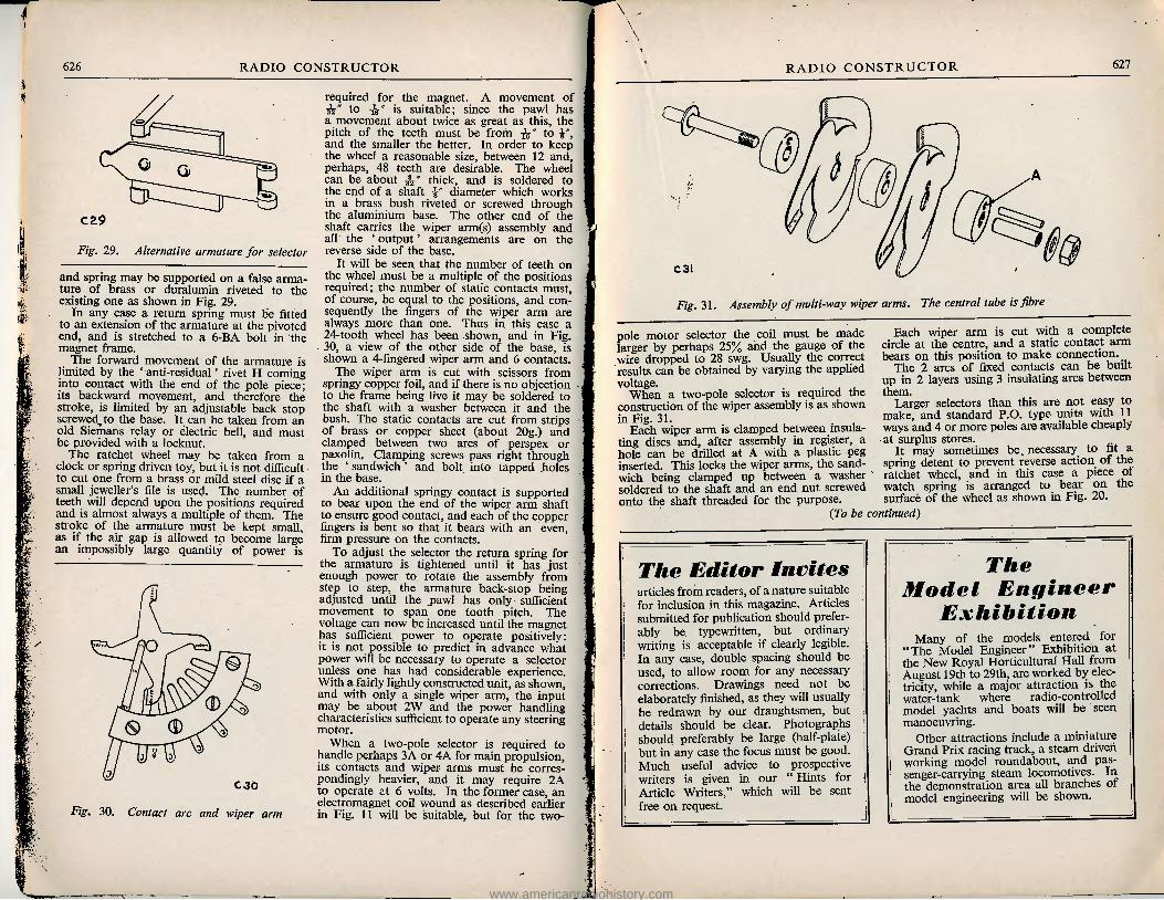
Fig. 31. Assembly of multi-way wiper arms. The central tube is fibre
pole motor selector the coil must be made larger by perhaps 25% and the gauge of the wire dropped to 28 swg. Usually the correct results can be obtained by varying the applied voltage.
When a two-pole selector is required the construction of the wiper assembly is as shown in Fig. 31. ,
Each wiper arm is clamped between insula- ting discs and, after assembly in register, a hole can be drilled at A with a plastic peg inserted. This locks the wiper arms, the sand- wich being clamped up between a washer soldered to the shaft and an end nut screwed onto the shaft threaded for the purpose.
Each wiper arm is cut with a complete circle at the centre, and a static contact arm bears on this position to make connection.
The 2 arcs of fixed contacts can be built up in 2 layers using 3 insulating arcs between them.
Larger selectors than this are not easy to make, and standard P.O. type units with 11 ways and 4 or more poles are available cheaply at surplus stores.
It may sometimes be necessary to fit a spring detent to prevent reverse action of the ratchet wheel, and in this case a piece of watch spring is arranged to bear on the surface of the wheel as shown in Fig. 20.
{To be continued)
The Editor invites articles from readers, of a nature suitable for inclusion in this magazine. Articles submitted for publication should prefer- ably be typewritten, but ordinary writing is acceptable if clearly legible. In any case, double spacing should be used, to allow room for any necessary corrections. Drawings need not be elaborately finished, as they will usually be redrawn by our draughtsmen, but details should be clear. Photographs should preferably be large (half-plate) but in any case the focus must be good. Much useful advice to prospective writers is given in our " Hints for Article Writers," which will be sent free on request.
The
Model Engineer
Exhibition
Many of the models entered for "The Model Engineer" Exhibition at the New Royal Horticultural Hall from August 19th to 29th, are worked by elec- tricity, while a major attraction is the water-tank where radio-controlled model yachts and boats will be seen manoeuvring.
Other attractions include a miniature Grand Prix racing track, a steam driven working model roundabout, and pas- senger-carrying steam locomotives. In the demonstration area all branches of model engineering will be shown.
www.americanradiohistory.com

' ~^-T^ TF% ■' ^ T^ x /^-'^IT -Itf T ;:.M.'X ■ :V/;t■•.H-A^' I \& ii' P j:- jf^L; .ft * 1 • ■'ftA^^Tf^wl»\J.Vm*»--Jft'--—'.W: .rs®:<lt t i',»I-A«*3>-r*»»rl sfewt :Vi-V
.'.«•». * i- /.i—v»*:V' ■ • ,,fc ^3*r";V WTR' * > Oki* * zm. Jj^vr.ittiiisakri. JEf-: Jc*- i
%te^v
A CHEAP and EFFICIENT CAR RADIO
We have pleasure in presenting this design for an Efficient, yet Inexpensive Car Radio Receiver. This receiver has been de- signed in two versions, one using ex-W.D. components and the other built around brand new material. Actually there is not a great deal of difference in the cost of either version, and where the Constructor has not a great deal of experience we should strongly advise him to use new material throughout. We have heard this receiver in operation and were impressed with the
performance.
By A. Tiel
The writer having recently taken delivery of a new Morris 8 and being interested as a radio amateur in portable transmitting and receiving
ili
Front view of the receiver made from sur- plus components
equipment, decided that it would be very pleasant when alone and on long journeys to have installed a broadcast receiver to help pass away the tedious hours on the road. Owing to the high price of the manufactured sets due to the purchase tax, the question of buying one of these was at once discarded. In consequence, the receiver would need to be built keeping the costs as low as possible by omitting the " frills " without loss of efficiency. To meet the first demand the surplus market was obviously the place to visit, as very many of the components which go to make a set can be acquired for a very reasonable outlay.
To make it compact, keep down cost, and to minimise switching, it was decided that only the medium waveband coils be fitted. This proved quite satisfactory, as it was found that very few drivers, when on the road, listened to the long or shortwave programmes, the " Light " and " Home " programmes being more satisfactory from the point of view of maintaining good reception.
The next question was where to house the set, as obviously it should be located within a comfortable distance of the driver's hand. It was found that on pulling out the grille in the centre of the dash, a hole approximately 4J"x3i" had been cut from the metal frame
628
RADIO CONSTRUCTOR
www.americanradiohistory.com

630 RADIO CONSTRUCTOR
H Ufvj IhhJOOO •o tv Oh
;ioG WO tvltfi cc ru -^wv
-O Q- o do: \ tvj^. UlNJ
^hi loU-
K ioQ -wv^-
vW*-* roC a: 5
4h fi ggci -^A-l II t
rA ii i i
vA/V ^ cr
a: P Q DC
DO -^ooo Q O
i rVW— L m
U-U
VW h
gyf^fc'^ r11
CTro VW< in nil.
a:* HtS-
QQOslP —I >-. -Q ujO~ OOQ^ ww 'A
11 l« » u? Oo o.o
Hh
U : -jm lUOM QUCt
>
<C cn o <
ZD O oz
o
□z o IS)
I o
cy vo 4
Ci.
*■ 5^
S^. 5c
RADIO CONSTRUCTOR 631
■ .
Urider-chassis view of the surplus version.
in order to facilitate wiring of the various controls. This looked to be an ideal position, as by moving one or two of the wires in the rear a clear depth of 11" was available. Also, to the left of this, below the glove box, was a circular hole of some 18" diameter just above the lower tray, which suggested a suitable position for the loudspeaker. Alternatively, the latter could be mounted behind the glove box lid, having first removed the medallion and fitted an expanded metal grille in its place.
Next the power supply. As very many excellent small surplus converters are still available, a type 104 12V input, 6V 3Amp/ 250V 100mA output was selected at a cost of 7/6 the same being completely smoothed and boxed. This particular one was chosen because the writer required other supplies for trans- mitting gear, but a much smaller type with
just a 250V 50mA output would have been quite satisfactory. This unit was then mounted under the car bonnet, fed from the accumulator through a switch in the car and the outputs brought out to a small perspex terminal strip fitted under the dash. On this strip were also mounted a pair of leads from the car battery to sockets supplying current for the valve heaters.
The aerial consisted of about 20-ft. of V.I.R. cable stretched under the car chassis and wound over and between the copper brake tubing to support it, this being fed in to the car through a hole in the scuttle to a socket secured under the dash. Later a roof whip aerial was fitted for comparative results. The whole was then wired up, the little set giving quite pleasing results for a very reasonably outlay.
Now a few words for those car drivers who
*
i
• .
Above-chassis view of the surplus version
www.americanradiohistory.com
632 RADIO CONSTRUCTOR
: ii
■
FRONT PANEL LAYOUT
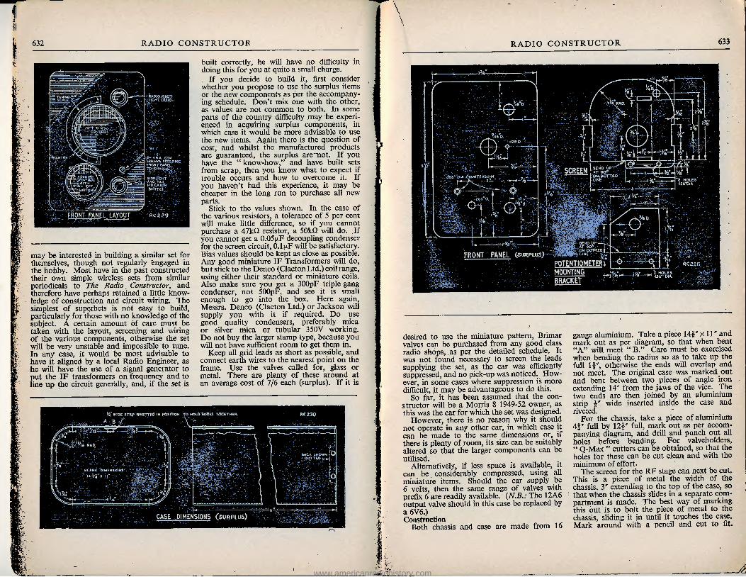
may be interested in building a similar set for themselves, though not regularly engaged in the hobby. Most have in the past constructed their own simple wireless sets from similar periodicals to The Radio Constructor, and therefore have perhaps retained a little know- ledge of construction and circuit wiring. The simplest of superhets is not easy to build, particularly for those with no knowledge of the subject. A certain amount of care must be taken with the layout, screening and wiring of the various components, otherwise the set will be very unstable and impossible to tune. In any case, it would be most advisable to have it aligned by a local Radio Engineer, as he will have the use of a signal generator to put the IF transformers on frequency and to line up the circuit generally, and, if the set is
built correctly, he will have no difficulty in doing this for you at quite a small charge.
If you decide to build it, first consider whether you propose to use the surplus items or the new components as per the accompany- ing schedule. Don't mix one with the other, as values are not common to both. In some parts of the country difficulty may be experi- enced in acquiring surplus components, in which case it would be more advisable to use the new items. Again there is the question of cost, and whilst the manufactured products are guaranteed, the surplus are not. If you have the " know-how," and have built sets from scrap, then you know what to expect if trouble occurs and how to overcome it. If you haven't had this experience, it may be cheaper in the long run to purchase all new parts.
Stick to the values shown. In the case of the various resistors, a tolerance of 5 per cent will make little difference, so if you cannot purchase a 47kn resistor, a 50kn will do. If you cannot get a 0.05 nF decoupling condenser for the screen circuit, 0.1 nF will be satisfactory. Bias values should be kept as close as possible. Any good miniature IF Transformers will do, but stick to the Denco (Clacton Ltd.) coil range, using either their standard or miniature coils. Also make sure you get a 300pF triple gang condenser, not 500pF, and see it is small enough to go into the box. Here again, Messrs. Denco (Clacton Ltd.) or Jackson will supply you with it if required. Do use good quality condensers, preferably mica or silver mica or tubular 350V working. Do not buy the larger stamp type, because you will not have sufficient room to get them in.
Keep all grid leads as short as possible, and connect earth wires to the nearest point on the frame. Use the valves called for, glass or metal. There are plenty of these around at an average cost of 7/6 each (surplus). If it is
r
RADIO CONSTRUCTOR 633
&
m it
01 i-O
FRONT PANEL (surplus) POTENTIOMETERI MOUNTING BRACKET
desired to use the miniature pattern, Brimar valves can be purchased from any good class radio shops, as per the detailed schedule. It was not found necessary to screen the leads supplying the set, as the car was efficiently suppressed, and no pick-up was noticed. How- ever, in some cases where suppression is more difficult, it may be advantageous to do this.
So far, it has been assumed that the con- structor will be a Morris 8 1949-52 owner, as this was the car for which the set was designed.
However, there is no reason why it should not operate in any other car, in which case it can be made to the same dimensions or, if there is plenty of room, its size can be suitably altered so that the larger components can be utilised.
Alternatively, if less space is available, it can be considerably compressed, using all miniature items. Should the car supply be 6 volts, then the same range of valves with prefix 6 are readily available. (N.B.: The 12A6 output valve should in this case be replaced by a 6V6.) Construction
Both chassis and case are made from 16
gauge aluminium. Take a piece 141" x 11" and mark out as per diagram, so that when bent "A" will meet " B." Care must be exercised when bending the radius so as to take up the full If", otherwise the ends will overlap and not meet. The original case was marked out and bent between two pieces of angle iron extending 14" from the jaws of the vice. The two ends are then joined by an aluminium strip i" wide inserted inside the case and riveted. , .
For the chassis, take a piece of aluminium 4f" full by 12i" full, mark out as per accom- panying diagram, and drill and punch out all holes before bending. For valveholders, " Q-Max " cutters can be obtained, so that the holes for these can be cut clean and with the minimum of effort.
The screen for the RF stage can next be cut. This is a piece of metal the width of the chassis, 3" extending to the top of the case, so that when the chassis slides in a separate com- partment is made. The best way of marking this out is to bolt the piece of metal to the chassis, sliding it in until it touches the case. Mark around with a pencil and cut to fit.
www.americanradiohistory.com

634 RADIO CONSTRUCTOR
9 ^ww
-Cl-I ww\ a <o
n.G I >—vvvw
I V ^VWW-H cc^
HVVVVV-H Uli-. or-
u,
[-VWV^f
Ligl, h
l!!!
I II i >—'VvVW
vrVW^-i
P i-A/ VWVi > - "-"VVVVV f-yVVW-<
tH
—wvw
II 111 o L^WwIHc
5
tH: ACS
> tC®
G
o<o OtO D 3
to Ui
V-' 1 CVf
T tQ Od «o a: T Cu
ID T eQ CM CD K cu - &J
-J •*c >
■LtOA 9 1
O ID
03 a: T Cu ID T CO 10
CO K T CO o §
->z > Sf 5 2 §
.O
*< x.
s-
g
RADIO CONSTRUCTOR 635
PARTS LIST, CAR RADIO USING NEW COMPONENTS
Resistors Rl, 3, 10 470 U, i-W, Dubilier type BTS R2 33 kQ, JW, Dubilier type BTS R4 27 kU, JW, Dubilier type BTS R5, 11 47 kO, iW, Dubilier type BTS R6 47 kO, 1W, Dubilier type BTB R7 22 kO, JW, Dubilier type BTS R8, 9, 13,16, 1 MU, iW, Dubilier type BTS R12 2 MO potentiometer (volume
control). R14 1 kfl, iW, Dubilier type BTS Rl 5 100 kU, JW, Dubilier type BTS R17 10 kfl, JW, Dubilier type BTS R18 330 Q, IW, Dubilier type BWF R19 10 kU, IW, Dubilier type BTB R20 270 kO, JW, Dubilier type BTS R21 150 O, JW, Dubilier type BTS Condensers Cla, b, c 300 pF 3-gang variable, J.B. or
Denco (Clacton) Ltd. C2, 5, 9 3-30 pF concentric trimmers C3, 14, 15 0.05 1J.F, 350V DCW, Dubilier
type 460 C4, 6, 7, 12,
13, 19 0.1 (rF, 350V DCW Dubilier type 460
C8 50 pF silver mica ±20% Dubilier type S635
C10 350 pF silver mica, ±10%, Dubilier type S635
Cll, 15, 16 100 pF silver mica, ±20% Dubilier type S635
C17, 22 0.01 |xF, 1000V DCW, Dubilier type 460
C18, 21 25 ij-F 25V DCW, Dubilier type BR
€20 2 to 8 ij-F, 350V DCW, Dubilier type BR
Coils LI Denco (Clacton) Ltd. type D/P,
Range 2, Blue L2 Denco (Clacton) Ltd. type D/P,
Range 2, Yellow L3 Denco (Clacton) Ltd. type D/P,
Range 2, Red IF Transformers, Denco (Clacton) Ltd. type IFTI1.
Valves All Brimar. According to car battery—see
circuit diagram.
Miscellaneous Case, chassis, panels, Denco (Clacton) Ltd. Valveholders, to suit valves used. Slow motion drive (epicyclic), extension spindle
and coupler, dial lamp holder, knobs, single mounting tag strips, screened sleeving, single pushback wire, sleeving, solder, screws, nuts and washers.
This also applies to the piece of aluminium carrying the volume control. Lastly mark out and drill the front panel as per sketch.
Should the facilities not be'available for this metal work, Denco (Clacton) Ltd. are supply- ing two types of chassis and cabinet. One is drilled for surplus valves as described in the Motor, with a radius on the comers of cabinet for fitting to the Morris 8, and the other is drilled for new Brimar valves and has a black steel cabinet with square corners suitable for any make of car.
The Morris cabinet is in aluminium, as is the original.
Next mount all components on the chassis, leaving the volume control until most of the wiring has been completed. Commence wiring the heater circuit using -flex or a twisted pair of insulated wires. Earth pin No. 1 on all valveholders when using the surplus valves. Bias circuits can then be wired up, except those for the 12SQ7, and 12A6 valves. These should be left until all other wiring is completed, the components being of such size that they would
be in the way of other wiring if connected. From then on it is a matter of choice how to proceed. The writer wired each circuit separ- ately, commencing at the RF stage and finishing at the output stage.
For calibration purposes a piece of white card was cut to 1J" radius, covered by a piece of clear perspex of the same size. This was slid behind the epicyclic drive and secured to the panel by two screws. A pointer was then added which moved over 180°. A bicycle spoke filed to a knife edge makes an excellent rigid pointer. The epicyclic drive and two indi- cator lamps were then mounted on the front panel, and the panel was then carefully fitted to the chassis so that the spindle of the three gang condenser was in line with the spindle of the drive. Before finally bolting this together, slide the coupler over the condenser spindle with the panel in position; no binding or springing should take place, and both spindles should easily enter the coupling.
{To be contined next month)
www.americanradiohistory.com

The "UNIVERSAL" Large Screen
jljXvX; AC/DC Televisor
Part 3. Described by A. S. Torrance, a.m.i.p.r.e., a.m.t.s. ( By kind permission of ikopatents ltd)
Assembly of Components For convenience in working, and at the same
time to avoid damaging these fragile parts, it is advisable to remove the CRT fixing straps (G).
The chassis may now be assembled either way up with greater safety and comfort. Power Pack Choke
Undo the fixing bolts and slip off the lamina- tion frame on the side where the connecting
wires are to be found. The choke is placed in the position shown in the photograph, and the frame bolted back under the chassis. The bolts should be well tightened to stop any subsequent vibration of the laminations.
Rectifier 14A/342 Make two simple " L" brackets, high enough
for the rectifier to clear the top of the chassis, and bolt into position over the air space pro- vided. The feet of these brackets turn inwards,
W»i
'
■JLj
CONTRAST (VOLUME
Left-hand side of chassis, showing smoothing choke 636
RADIO CONSTRUCTOR 637
TUBE COATING GONNECTORV
Right-hand side of chassis
and the connection plates of the rectifier are placed underneath. Condensers
C48-C52 and C39-C43, together with the 60/100 gF, are now mounted with clips on top of the chassis, as shown. Frame Blocking Oscillator Transformer
Mounted under the chassis, as shown. HT and Heater Droppers
Mounted on top of the chassis, at the rear. Tag Strips
Carefully count the number of tags on each strip, and bolt underneath in their correct positions. The tag part of the bolt fixing, in each case, is required for chassis contacts and should not be removed. In addition to those shown in the heater point-to-point diagram, one 2-way strip is required for the frame transformer—see photo. Rear Controls and Aerial Socket
Cut a piece of perspex, plastic, paxolin or other suitable insulating material to cover the entire length of the rear end of the chassis. This may well be made of a greater depth than is shown in the photograph, thus affording more protection against contact with the fuse- holders.
Drill clearance holes for the control bushes and aerial socket. Bolt the latter into position with countersunk headed bolts. Slide the material over the bushes and secure into position with the potentiometer nuts. The spindles may then be cut shorter, leaving sufficient length for the knobs. These latter must be of the type having deep-seating grub screws.
This procedure effectively protects the opera- tor from contact with the chassis when making adjustments. Note that the bushes for the focus mechanism are also insulated. Front Controls
Instal in position as shown. It is advisable to attach the engraved knobs before wiring— this will assist the constructor in avoiding any possibility of crossing the connecting wires. Line Output Transformer
This component should not be mounted at this stage—it has delicate wiring, and during the wiring-up procedure may be subjected to con- siderable handling, with subsequent damage. Instal Valveholders, selecting the appropriate type for each valve as specified in the heater
www.americanradiohistory.com

638 RADIO CONSTRUCTOR
One side of mains via switch PING TO Suit mains NOTE! All mains inputs should be direct to 2 amp
fuses, thence to DP switch , then to heater chain s rectifier
v 16 Choke (top)
Line outp: " trans. , Y vent ^top)- I hole MW 43-64
VA OOb
Frame output v trans Vs (top)
VI4 VI2 Speaker -^ s
Ntrans;^- X '
Sides of chassis shown flat to trlanfy wiring
UNDERSIDE OF CHASSIS SHOWING HEATER CHAIN WIRING & DISPOSITION OF TAG STRIPS, VALVE LOCATIONS, ETC
chain diagram, and parts list. This is import- ant. It must be understood that some valves are carrying VHP signals, and any losses incurred through faulty or poor quality holders will inevitably destroy the high definition capable of resolution by the " Universal" televisor. The VA1008 and the A2/1 may now be soldered in parallel and in their allocated position. The Heater Chain Wiring
Careful study should now be made of the
under-chassis point-to-point wiring diagram of the heater chain.
DO NOT DEVIATE FROM THE LAY- OUT GIVEN.
This has been carefully devised to give maximum stability and freedom from parasitic oscillation, sometimes present in series-heater arrangements.
Commence, then, at V2. The first connection will be pins 4 and 5 (joined externally) to chassis. Proceed through the chain exactly as shown. Good quality PVC or tinned copper
RADIO CONSTRUCTOR 639
Rear view, showing rear controls and insulating mounting panel
•s-
ILL
r
m
«1» 't ENST: VHOLD DRIVE V.HBGHT
and sleeving must be used. Do not use push- back type wire. Maximum insulation is imperative.
Note the tag strip provided for eventual heater supply to the MW43-64. Flexible leads will be required for this, and will be added later.
C66, C67 and C68 are not shown in the point-to-point diagram, but should be soldered into position now (see heater chain section of circuit).
Testing the Chain for Insulation Make a temporary " short" across the
CRT heater tag strip (shown as 1.12. MW43- 64). Insert all the valves with the exception of V2. With a continuity meter check the chain right through from the DK37/6 heater dropper to pin 9 of V2. There must be continuity—the actual resistance reading obtained will be fairly high due to the heater dropper and A2/1.
www.americanradiohistory.com
640 RADIO CONSTRUCTOR
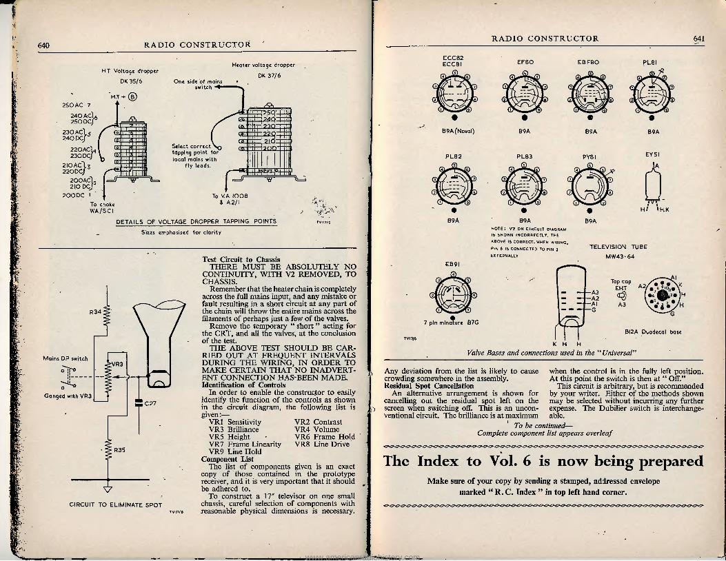
HT Voltage dropper DK 35/6
250AC 240 ACl 6 250 DC
230ACI 240 DCJ
22 O ACl. 230DCJ
2IOAC1 j 220DC/
200AC1 2IO DCj
200DC •
H.T+ (5)
c=Jl •w
One side of mains switch
Select correct tapping point for local mains with
fly leads
Heater voltage dropper DK 37/6
25U 240
22Q
?nn—
=5 -w
DETAILS OF VOLTAGE DROPPER TAPPING POINTS Sizes emphasised for clarity
Mains DP switch
R34
VR3
C 27
R35
Ganged with VR3
CIRCUIT TO ELIMINATE SPOT
Test Circuit to Chassis THERE MUST BE ABSOLUTELY NO
CONTINUITY, WITH V2 REMOVED, TO CHASSIS.
Remember that the heater chain is completely across the full mains input, and any mistake or fault resulting in a short circuit at any part of the chain will throw the entire mains across the filaments of perhaps just a few of the valves.
Remove the temporary " short" acting for the CRT, and all the valves, at the conclusion of the test.
THE ABOVE TEST SHOULD BE CAR- RIED OUT AT FREQUENT INTERVALS DURING THE WIRING, IN ORDER TO MAKE CERTAIN THAT NO INADVERT- ENT CONNECTION HAS BEEN MADE. Identification of Controls
In order to enable the constructor to easily identify the function of the controls as shown in the circuit diagram, the following list is given:—
VR1 Sensitivity VR3 Brilliance VR5 Height VR7 Frame Linearity VR9 Line Hold
Component List The list of components given is an exact
copy of those contained in the prototype receiver, and it is very important that it should be adhered to.
To construct a 17" televisor on one small chassis, careful selection of components with reasonable physical dimensions is necessary.
VR2 Contrast VR4 Volume VR6 Frame Hold VR8 Line Drive
RADIO CONSTRUCTOR 641
ECC82 ECC8 I EFSO
B9A (Noval) B9A
EBF80 PLSI
B9A B9A
PL82 PL83
3? 3
EB9I
PY8I
B9 A B9A
EY5I
A
fcsscsd "I *H.K
note: V7 on circuit diagram IS SHOWN INCORRECTLY. THE ABOVE IS CORRECT. WHEN WIRING, PIN 6 IS CONNECTED TO PIN 3 EXTERNALLY
TELEVISION TUBE MW43-64
7 pin minalurc B7G
Top cap A2 EHT & A2
A3
BI2A Duodecal base K H
Valve Bases and connections used in the " Universal"
Any deviation from the list is likely to cause crowding somewhere in the assembly. Residual Spot Cancellation
An alternative arrangement is shown for cancelling out the residual spot left on the screen when switching off. This is an uncon- ventional circuit. The brilliance is at maximum
when the control is in the fully left position. At this point the switch is then at " Off."
This circuit is arbitrary, but is recommended by your writer. Either of the methods shown may be selected without incurring any further expense. The Dubilier switch is interchange- able.
To be continued— Complete component list appears overleaf
The Index to Vol. 6 is now being prepared
Make sure of your copy by sending a stamped, addressed envelope marked " R. C. Index " in top left hand corner.
www.americanradiohistory.com

642 RADIO CONSTRUCTOR
Universal Televisor
LIST OF COMPONENTS Deflection Coils- -WA/DCA l —Denco (Clac-
ton) Ltd. Line Output Transformer—WA/LOT1—Den-
co (Clacton) Ltd. Power Pack Choke—WA/SCI—Denco (Clac-
ton) Ltd. Frame Output Transformer^—WA/FMA1—
Denco (Clacton) Ltd. Frame Blocking Transformer—WA/FBT1 —
Denco (Clacton) Ltd. Width Control—WA/WCl—Denco (Clacton)
Ltd. Line Linearity Control—WA/LC1—Denco
(Clacton) Ltd. Vision/Sound Coils—"' Universal " TV—
Denco (Clacton) Ltd. Correction Chokes 1-2-3—" Universal " TV—
Denco (Clacton) Ltd. Chassis and Structure—" Universal " TV—
Denco (Clacton) Ltd. Focus Mechanism—" Universal " TV—Denco
(Clacton) Ltd. Cans for L4-L5, L7-L8—" Universal " TV—
Denco (Clacton) Ltd. Cabinet—" Universal " TV—Lasky's (Harrow
Road) Ltd. Perspex—" Universal " TV—Lasky's (Harrow
Road) Ltd. Escutcheon (White)—" Universal" TV—
Lasky's (Harrow Road) Ltd. Duomag Focaliser—FD12/4—Elac. 5" Speaker—5/45—Elac. Speaker Transformer—18009—Elac. Ion Trap Magnet—IT9—Elac. Rear Control Knobs—5x1" with deep seating grub screws—(Uncles Bliss) Lasky's (Harrow
Road) Ltd. Valveholders—See heater chain—Mc'Murdo. Aerial Connector—AA/3UB—Mc'Murdo. Aerial Socket—B3/US—Mc'Murdo. Power Pack Rectifier—14A/342—Westing-
house. i" Felt for packing—See tube mounting— Lasky's (Harrow Road) Ltd. Double Fuseholder—2A fuses—Lasky's (Har-
row Road) Ltd. Single Fuseholder—250mA fuses—Lasky's
(Harrow Road) Ltd. Knobs for Front—with deep seating grub
screws—Brilliance, Volume, Contrast, Focus. See text for " On/Off" methods—(Uncles, Bliss), Lasky's (Harrow Road), Ltd.
Insulated Bushes for Focus Mechanism— " Universal " TV—Denco (Clacton) Ltd.
Half Links for Focus Mechanism—" Uni- versal " TV—Denco (Clacton) Ltd. Top Cap for MW43-64—Lasky's (Harrow
Road) Ltd.
sED IN THE PROTOTYPE Top Cap for PL81—Lasky's (Harrow Road)
Ltd. Top Cap for PY81—Lasky's (Harrow Road)
Ltd. Heater Chain Dropper—DK37/6—J. L. Golds-
man Ltd., distributed by Amplion. HT Dropper—DK35/6—J. L. Goldsman Ltd.,
distributed by Amplion. Miscellaneous Resistors across deflection coils—Supplied by
maker. Spring steel, brass, or phosphor-bronze wire
for connecting tube coating to chassis. Tag Strips—Solder Tags—Nuts and screws. Valves All Mullard—See heater chain circuit.
Condensers. All T.C.C. Available complete and boxed. Cl, lOOOpF, CTH310 C35, 47pF, 101SMP C2, lOOOpF, CTH310 C36, O.OlfrF, 543 C3, lOOOpF, CTH310 C37, 220pF, SCT14 C4, 47pF, 101SNP C38, 200pF, SCT14 C5, 10pF, 101SNP C39, 32ixF, CE27LEt C6, lOOOpF, CTH310 C40, 0.01 [xF, 543 C7, 47pF, 101SMP C41, 0.01(xF, 543 C8, 22pF, 101SMP, C42, 50u.F, CE32B
Finish "C" C9, 47pF, 101SMP C43, 32!iF, CE27LEt C10, lOOOpF, CTH310 C44, 0.01|xF, 543 Cll, lOOOpF, CTH310 C45, 0.1 [xF, 343 C12, 47pF, 101SMP C46, 0.1|xF, 343 C13, Supplied with coil C47, 0.01 jxF, 543 C14, lOOOpF, CTH310 C48, 32|xF, CE27LEt C15, lOOOpF, CTH310 C49, 0.5!xF, 500CP915 C16, 47pF, 101SMP C50, 0.05ixF, 343 C17, lOOOpF, CTH310 C51, I00|xF, CE61C C18, Supplied with coil C52, 32[xF, CE27LEt C19, lOOOpF, CTH310 C53, O.OSixF, 343 C20, 47pF, 101 SMP C54, 0.02ixF, 543 C21, lOpF, 101SMP C55, 0.05(xF, 543 C22, 0.05g.F, 343 C56, 0.01 [xF, 543 C23, 8[xF, CE11L C57, 0.02.xF, 543 C24, lOOOpF, CTH310 C58, 3300pF, CTH315 C25, 2200pF, CTH3I0 C59, O.OOSixF, 543 C26, 0.1 [xF, 343 C60 82pF, SCT2 C27, 0.1 jxF, 343 C61, 82pF, SCT2 C28, 0.1 ixF, 743 C62, 680pF, 601 SMP C29, 10,000pF,CTH422C63, 400pF, 501SMB C30, lOOOpF, CTH310 C64, 0.5|xF, CP915 C31, Supplied with coil C65, 47pF, SCT1 C32, lOOOpF, CTH310 C66, lOOOpF, CTH310 C33, Supplied with coil C67, 10,000pF,CTH422 C34, 0.01 ixF, 543 C68, lOOOpF, CTH310
3 Clips for Top Mounted Condensers. 2 Side-fixing Clips for C51, C23.
RADIO CONSTRUCTOR 643
Power Pack Condensers. 60/100ixF, CE37LE
NOTE.—32|xF is C52. The un-marked con- denser between R56 and chassis in the circuit diagram is C45.
The condenser across the line deflection coils is provided by the makers.
*=Same Can. t=Same Can. Resistors. All Dubilier, available complete and boxed. Rl, R2, R3, R4, R5, R6,
4.7kO BTS 3312 BWF2 10011 BTS 4.7kn BTS 1.5ka BTS 2.7kn BTS
R7, 22ka BTS R8, 6800 BTS R9, lOkOBTS R10, 2.7kn BTS Rll, 1500 BTS R12, 6.8kO BTS R13, 1.5kO BTS R14, LSkOBTS R15, 2.7kO BTS R16, 330 BWF2 R17, 1000 BTS R18, 1500 BTS R19, 3.9kO BTS
R20, 1.5kO BTS R21, 4.7MO BTS R22, 5.1kO BTS R23, 22kO BTS R24, lOkO BTB* R25, lOkO BTB* R26, 22kO BTS R27, 470 BWF2 R28, 220kO BTS R29, 5.1kO BTS R30, 3.3MO BTS R31, 33kO BTS R32, 1MO BTS R33, 3.3kO BTS R34, 220kO BTS R35, 22kO BTS R36, 2.2MO BTS R37, 470kO BTS R38. 22kn BTS
R39, 1,5kO BTS R40, 150O BTS R41, lOOkO BTS R42, 220kO BTS R43, 10MO BTS R44, 2.2MO BTS R45, 1MO BTS R46, 33kO BTS R47, lOkO BTS R48, 1000 BTS R49, lOkO BTS R50, 1.5kO BTS R51, 2700 BTS R52, 220kO BTS R53, lOkO BTS R54, 470kO BTS R55, lOkO BTS R56, lOOkO BTS
R57, 33kO BTS R58, 220kO BTS R59, lOkO BTS R60, 22kO BTB R61, 3900 BTS R62, 47kO BTS R63, 2.2MO BTS R64, 3.3MO BTS R65, 4.7kO BTB R66, 470 BWF2 R67, 1MO BTS R68, 220kO BTS R69, 22kO BTS R70, 82kO BTS R71, 47kO BTS R72, 1.5kO BTS R73, 3300 BTS R74, 82kO BTB
*=Or one 4.7kO 2W R850 Heater-Chain Series Resistor, 7500 2N. A2/1. Varite Resistor, VA1008, (Mullard) (In
Parallel). VR1, 25kO CB VR6, lOOkO CB VR2, 2.5kn CA VR7, lOOkO CB VR3, lOOkO CB VR8, lOOkO CB VR4, 500kO CIS VR9, lOOkO CB VR5, 2MO CB Resistors across deflection coils supplied by
maker.
Second National Handicra
The inaugural Handicrafts and Hobbies Exhibition.in 1952 at Central Hall, Westminster, conceived primarily for a vast public interested in seeing and purchasing British handicraft materials, attracted nearly 50,000 visitors from all parts of the country. With preliminary arrangements well in hand, it is confidently anticipated that at least double the number of visitors will flock to Central Hall during September 17th to 30th. Admission price is one shilling.
t and Hobbies Exhibition
A wide and varied range of interests is catered for by 125 Exhibitors covering:— Marquetry; Modelling; Artificial Jewellery; Weaving and Spinning; Woodwork and Carpentry; Basketry; Book-binding; Leather- work; Toy-making; Embroidery; Knitting; Home-decorating; Wireless; Television; Stamp-collecting; Gardening; Preserve-making; Sweet-making; Pottery-throwing; Glass-blow- ing; Model Railways and Model Ships.
STOP PRESS-Test Card "C"
We have now received the text of Sir Ian Jacob's reply to Mr. Charles Ian Orr Ewing, M.P.
This gives the information that the approach of the British Radio Equipment Manufacturers' Association for extended radiation of the Tuning Signals was made jointly with The Radio and Television Retailers' Association Ltd.
At the discussion, the B.B.C. suggested that it would be more convenient for everyone concerned if, instead of extending the duration of the clock tuning signal, this was to be preceded by a ten-
minute period of Test Card " C " accompanied by a tone signal. This was agreed.
The necessary apparatus has now been delivered and installed, and is in operation. In future, it is the B.B.C.'s intention to precede every period of programme transmission by about a quarter-of- an-hour of " lining-up" signals. These will normally consist of the trade Test Card and tone for ten minutes, followed by four minutes of the Clock caption and music.
In addition the B.B.C. will fill the gap (normally about 45 minutes) between the end of the after- noon transmissions and the start of Children's Television by radiating Test Card " C " and tone.
www.americanradiohistory.com
RADIO CONSTRUCTOR 645
Sodio Miscellany
for more than a few. At present it would need a couple of extra pockets in the TV cabinet—one to hold the tinted spectacles and the other for the packets of head-ache powders! * * ♦ *
A recent development has been the deaf aid adaptor which enables the user to listen to broadcast programmes at will. It is but a step to the built-in radio unit which will form a combined portable and deaf-aid.
It starts one wondering what the license position will be. At present a fixed address license covers the occasional use elsewhere of a portable set. It could well be argued that any use of a deaf-aid as a radio receiver must necessarily be occasional—on the occasions when it is not being used as a deaf-aid! * * * *
The recent press prominence given to the radio taxi dispute brings home how extensive the use of radio has become in the taxi and car hire business. No doubt most readers have heard of instances of instructions being radioed to a driver who, on arriving at the address given, finds that a rival firm have nipped in and already picked up the passenger. No doubt some of these cases are the result of genuine mistakes but many have a flavour of a new line of " piracy."
Perhaps some enterprising firm will introduce scrambled speech to confound would-be hi-jackers 1
inosity is likely to go on without noticeable loss of intensity for tens of thousands of years more, is somewhat naive. Even its minor aspects require a life-time's study and of its composition we can only hazard guesses.
Made of the best coal it would give barely a millionth part of the energy emitted and would finish up as a cinder in less than six thousand years. Yet a study of fossfl remains clearly indicate there has been no appreciable fall in its radiated energy over thousands of years.
Its nature must remain completely unknown to us until we have learned a lot more about the radio-active elements. If the sun was composed of solid uranium it would generate only a third of the energy it emits!
As the maximum effect of sun-spots occurs between 4 to 6 metres (sometimes reaching nearly 100,000 times greater level than the normal receiver noise) it is likely that there will be considerable disturbance of British TV reception. Perhaps that way we shall get as much mass observation, or rather the lack of it, that we want! The most probable effects will be high noise level and complete fade-outs. Even then people will probably blame their receivers!
It is surprising how many viewers look for faults in their sets when the trouble is at the transmitting end. There must inevitably be camera faults etc., and I often wonder how many viewers at the first sign of trouble leap up and tinker with the controls. Oddly
Centra Tap talks about
iiinaiggHiHaiiniHiiiHiiiiiiii WOOD'S METAL-
■l
-THIS AND THAT 1 iiiiiiiiiiiiiiffliiiiiiiiiifflifii
Old Timers of the crystal set era will remem- ber Wood's metal (50% Bismuth, 25% Lead and 124% each of Tin and Cadmium). In 1923-26 it was widely used for mounting crystals in their brass cups as its melting point (66 to 70 degrees Centigrade) was unlikely to damage the crystal. In those days one could buy it at practically every wireless shop, although in recent years even the best radio suppliers have not stocked it. It had a minor burst of popularity in post- war years for use in thermal fuses but as far as I could discover it was still only obtainable from suppliers of laboratory materials etc., or from the Old Timers' junk boxes. By decreasing the amount of cadmium to 11% and bringing the tin up to 14%, an alloy with a melting temperature as low as 50oC. is obtainable, and this can be brought still lower by the addition of mercury.
Those who have been lucky enough to have a little low temperature solder in hand, have been sparing in their use of it. Not because it was expensive but because it was such a nuisance to replenish one's stock. It is therefore of great interest to see that Multi- core are marketing a handy pack in the form of a card on which is wound approximately a 5 feet ribbon of " melt with a match " solder containing its own non-corrosive flux.
It retails at a shilling. It will be most useful on a Field Day or when joining aerial wires on a roof when you cannot take a soldering iron. Spliced wires are best joined by binding the solder-tape around the joint and heating with a naked flame.
It can, of course, be equally well used in the workshop with a warmish iron, and is especially suitable for fine wiring and delicate components which are always liable to injury if the heat from a high temperature iron is applied to them too long. A sample recently tested gave strong and electrically sound joints, with the ease the makers claim for it. On behalf of constructors I particularly welcome this re- appearance of a readily obtainable low tem- perature solder, and the thermal fuse experi- menter will find it is just what the doctor ordered. The tape can easily be cut into wire- like strips and if necessary, beaten out to a
fine gauge. Such safety fuses often take the form of two strips of springy brass, the tips of which are held together by a film of low temperature solder. Upon overload the solder melts and the circuit is broken as the contacts spring apart. It will be found in practice that the contacts break apart before the melting point is reached. All fusible metals go " pasty " before the melting point is reached, and thus weaken the circuit- breaking contact. Aluminium and All That
Talking of solder reminds me that I am often asked about the soldering of aluminium, either by heat or paste.
The latter can be dismissed quite simply. Certainly none of the soldering pastes I have heard of are any good at all for electrical connections, and none of those I have tried have any mechanical strength worth mention- ing. They are useful, however, for stopping small holes and odd jobs of that nature.
Of other methods there have been recent developments in the ultrasonic soldering of aluminium and its alloys which are claimed to work very satisfactorily. It is apparently done by applying sound vibrations at some 20,000 c/s when a firm job is said to result. I have not seen any specimens of the work nor any exact details of what happens. Maybe the oxidised surface film is broken down, or alternatively the solder might grip on minute irregularities in the metal rather than provide a true fusion.
While the uses of the ultrasonic system is claimed to be becoming more widely recognised industrially any form of aluminium soldering iron for home use still appears to be a long way off. Nevertheless it's a pleasing thought that one day we shall be running a seam along a couple of sheets of ali with a vibratory soldering gun! Odds and Ends
Following my comments of a couple of months ago, I have been surprised at the number of readers who have written to say they would prefer to have stereoscopic rather than colour TV. Unless some new optical system is developed I cannot imagine that stereoscopic TV will have much attraction
Sun Spotting The next sun-spot cycle is being suggested
as a subject for amateur mass observation on a world wide scale. We have certainly to learn much of the effects of sun-spots on radio communications but such an effort would probably serve better as a full-dress rehearsal for other forms of observation, rather than learning much more of their nature. We already know much of their effects, but some of the tricks they have been reported as playing (such as tripping relays etc.), are quite unaccountable. It is not the effect of the phenonema but the causes which remain such a mystery.
There is, of course, much still to be learned of the sun itself. When one first seriously ponders on its nature, a realisation that former vague and school-boyish ideas of it being a fiery mass some 92,000,000 miles away which, although it has passed the prime of its lum-
enough the B.B.C. don't seem to think it necessary to tell viewers that the trouble was their end until any old time up to a couple of hours later. Puzzle Corner
I suppose a good number of readers keep a Scrap Book of sorts. I have had one for a good many years which I irregularly keep. It contains numerous circuits, details of unusual and continental valves, component literature, formulae for quick drying paints, polarity testing and home-made wax polishes, etc. When it gets too voluminous one has to wade through and turn out all the out-of-date gen. It was in the process of " stripping" mine some months back that I came across the entry " No. 3 size."
This entry was obviously made years ago; as far as I could judge somewhere about 1939. For months I was puzzled as to what it
{continued on page 647) 644
www.americanradiohistory.com

Query Corner
A Radio Constructor service
for Readers
Frame Non-Linearity / have built a television receiver according
to the information given in your booklet entitled Inexpensive Television. The result was very good and I have but one criticism: the linearity of the frame timebase is poor, the picture being badly cramped at the bottom. Most of the components associated with the frame timebase have been changed without producing any reasonable degree of improvement. Have you any suggestions^.
K. Knowles, Harrow
Many hundreds, or possibly several thous- ands, of these televisors have been made to date, and in the main the results appear to be most satisfactory. However, from time to time a complaint of poor frame linearity is received, a fault which has defied all the corrective efforts of the constructor. In some cases the root of the trouble can be traced to insufficient HT supply voltage to the timebase unit. If scan distortions are to be avoided a voltage of at least 450V is required and best results are usually obtained with a supply of between 500 and 600V. It will be appreciated that the higher the EHT voltage applied to the cathode ray tube the lower will be its deflection sensitivity and the greater will be the output required from the timebases. Sometimes, the poor linearity can be attributed to a faulty valve or leaky capacitor, and such points can be readily checked by making substitutions.
However, in stubborn cases it is probably better to use a slightly different frame amplifier circuit, and the one about to be described can be recommended to all those who wish to obtain a near perfect vertical scan. The arrangement differs from the original largely in the method of phase splitting, and it has the advantage that a linearity control is pro- vided. The output from the transitron used as a frame oscillator is a negative going saw- tooth, and this waveform is applied to the
grid of the first half of the double triode. The anode of this valve carries a positive going sawtooth, a fraction of which is fed to the grid of the second half of the valve. Consequently, the anode of this section carries a negative going voltage which is substantially equal in amplitude but opposite in phase to that on the first anode. The degree of equality of these two voltages is dependent upon the values of the two arms of the dividing network between the two anodes. In certain cases, some improvement may be obtained by adjusting the balance by varying Rl. The linearising circuit consists simply of an adjust- able R-C combination across the anode of the first valve. This has the effect of correcting for any distortion which may be introduced by the curvature of the valve characteristic.
Extending CR Tube life I have read with interest articles on the
subject of rejuvenating television tubes, as the tube in my receiver is now giving a very dim picture. Would you recommend that I have the tube reactivated in an effort to prolong its life!
D. Sayers, London
An appreciable extension in the life of a television tube can be obtained when the only fault which the tube has developed is low cathode emission. This increase in life can be obtained in one of two ways, by a process known as cathode reactivation or by simply raising the heater voltage of the tube. In many ways the results of the two techniques are the same in that they bring to the working surface of the cathode more electron emissive material. However, to avoid waste of time and money it is necessary to be able to recognise a tube which will respond to treatment. The visible symptoms of poor cathode emission are a dim picture which lacks any highlights and has a tendency for the flyback lines to appear on the picture when the controls are set for
646
RADIO CONSTRUCTOR 647
HT t (4S0-S50V)
125 k a; resfen
HI—
6SN7
scyjp SOV
R! * 220 *
— J220 : kn
Jo^f
TO Y PLATES
12MF
3-3 • bn ' -2Ma HMO
-LINEARITY
FIG. I
RC 251 IMPROVED FRAME TIMFBASE AMPLIFIER■ UNMARKED COMPONENT VALUES REMAIN UNCHANGED
the best results. Now, providing the tube has no other faults in the form of poor inter- electrode insulation, a damaged screen or impaired vacuum, rejuvenation can be attemp- ted. A tube which has a poor vacuum is recognised by poor focus, and there is little to be gained by any effort to extend its life.
Having decided whether it is worthwhile to attempt to improve the cathode emission, the choice lies between reactivating it or merely increasing its heater voltage. Of the two methods, the writer favours the latter as it appears to provide the most consistent improve- ment on tests made on a number of tubes. It is important that the heater voltage is not increased by more than is necessary and if it is done progressively in steps the maximum life can be coaxed from the tube. Increases of 12%, 25% and 33% have been found to give the best all round results, and the only problem which remains is to decide how to obtain the additional voltage. Perhaps the most convenient method is to add a few more turns around the core of the mains trans- former. Most of the larger transformers are wound to 4 or 5 turns per volt so that to obtain, for example, another half volt, two turns must be added. The extra turns are joined in series with the existing tube heater supply source, but care is necessary to connect the two voltages in the correct phase. If the additional winding is connected in antiphase then the resulting heater voltage will be reduced. Having connected up the windings, the voltage should be checked with an accurate AC voltmeter. A simple check to determine how many turns per volt are used on the mains transformer can be made by adding a
test winding of, say, 4 turns and then measuring the voltage across it.
If space does not permit the addition of a winding as discussed above, the increased heater voltage must be derived from a separate transformer. This is not usually an expensive proposition, and quite often a good quality 3 or 4 watt output transformer can be pressed into service. The primary is connected to the mains and the voltage measured across the secondary. The secondary is then unwound and the number of turns noted. This indicates the turns required when rewinding to provide the tube heater voltage. Whilst doing this job it is worth while adding the extra tapping points to provide the percentage increases already quoted. This will enable further periods of extended life to be obtained after the first increase has become ineffective.
Normally there is little danger of damaging the tube heater by small voltage increases, but in time the heater-to-cathode insulation may break down. Anyway, it may be possible to extend the tube life by a year or more, but if only a few extra months are obtained the effort will have been worth while.
Radio Miscellany — {Continued from page 645) referred to, and why it was there, until finally I gave it up as one of the unsolved mysteries.
Last week I found out what it was, or to be more strictly correct, re-discovered it. It is the basis of an extremely useful hint and I wonder how many readers know what it is. The answer will appear in this column next month and in the meantime here is a clue. Its uses extend beyond the universal. That should make it easy.
www.americanradiohistory.com

OSCILLOSCOPE TRACES
by A.B.
@
//
/
o +
BASIC AF AMPLIFIER SHOWING OSCILLOSCOPE TEST POINTS
No. 2. The oscilloscope as a means
A reasonably pure sine wave input voltage is essential for this particular method, which is one of several systems used. If an audio signal generator is not to hand, the heater winding of a mains transformer could be used. A potentiometer,should be connected across the heater winding in order that the voltage to the amplifier can be varied.
of checking distortion in AF amplifiers.
A waveform as shown in A is quite suitable but, due to its small amplitude, it wouldjhave to be applied to the CRT plates via the oscU- loscope amplifier. Care must be taken to ensure that the oscilloscope amplifier does not distort this waveform, by keeping the gain as low as possible, consistent with a comfortable size picture on the screen.
648
RADIO CONSTRUCTOR 649
The signal voltage at the anode of a stage should be an enlarged version of A, if no distortion is present. B, however, shows the effect of incorrect biasing or slight overloading. If this occurs the input voltage to the stage should be reduced. Really severe overloading is shown in C, where considerable grid recti- fication is taking place.
The technique with multi-stage amplifiers is to work through the circuit from stage to stage until a noticeable departure from the input waveform is observed.
When carrying out these checks the leads from the test point to the oscilloscope should be kept as short as possible, otherwise the amplifier may oscillate.
Transistors—The Crystal
Comes Back Again
By T. W. Dresser
In the course of the last four or five years there have appeared in the technical press references to a mysterious device called a Transistor, which, if the claims made for it are substantiated, may very well spell the doom of the valve for many purposes ultima- tely; as far as receiver and low power uses are concerned, anyway. That the claims made are far from wild ones can be judged from the fact that, recently, a television receiver was exhibited in New York which used nothing but Transistors throughout; not one single valve other than the picture tube was employed! At the same time a finger ring radio, using two transistors, was shown, which was no greater in size than an ordinary signet ring. This question of size, quite apart from then- other advantages, is of immense importance today when miniaturisation, particularly for aircraft and military purposes, is becoming an essential thing, and the fact that twenty or more transistors take up no more space than one valve is a big factor in their development.
Coming down to basic facts, the transistor is simply a Germanium crystal used as a valve, though with certain important differ- ences due to their differing characteristics. Just as a triode valve has three electrodes, so also has a transistor, but whereas in the valve free electrons in vacuo are utilised for the operation, the transfer of electrons in the transistor is based upon a totally different conception, which is not particularly easy to follow.
The block schematics of a contact type and a junction transistor are given in Fig. 1, the three elements in the first named corresponding to the cathode, grid and anode of a triode
valve and functioning in much the same way, though not necessarfiy with the same results as, for reasons which will be explained later, transistors require circuits designed specifically to suit their own characteristics. Nevertheless, transistors can be used successfully in multi- vibrators, amplifiers for RF and LF work, oscillator circuits and in many other places where valves would normally be used. An instance of transistor technique is given in Fig. 2, which is the diagram of a small LF amplifier using a standard contact type trans- istor and which can be built into a case measur- ing 2" x 1.5" X 1.5". The amplifier has a response curve sensibly flat from 20 cycles to 20,000 and a voltage gain of 50 when working into the correct output impedance. The maximum input voltage of such an amplifier is 0.1 RMS, and the maximum per- missible output slightly less than 5 volts RMS, and the instrument functions from a 30 volt deaf-aid battery with a total current drain of 2 mA. Output noise level, with no input signal and the input terminals open, is 0.015 volts RMS, or approximately 50 db below the maximum signal output. It will be readily seen that this circuit is not so very different to that of a single triode valve LF amplifier if the base is regarded as the cathode, the emitter as the grid and the collector as the anode, and many experimenters have used transistors successfully in modified valve circuits.
At the moment there are two types of transistors available, the contact and the junction or N-P-N types. The former is merely a thin slice of Germanium, cut from a single crystal, and having two catswhisker
www.americanradiohistory.com

650 RADIO CONSTRUCTOR
Emitter Collector
j Cosing \ / \ /
Bast
CONTACT TYPE
Collector
Emitter
Base
N.P.N. OR JUNCTION TYPE
FIG.I
wires in close proximity in contact with its surface, the whole being enclosed in the form of a small bead. The crystal is mounted on a base of a non-rectifying character. One such unit will have a gain of approximately 20 db, a life of about seventy thousand hours, and will function well from a low voltage source of power with a consumption of one or two mA. The junction type, a later development, is a much improved version, consisting of two sections of normal Germanium, as used in the contact type, with a small piece of P Germanium inserted between them. Stated briefly, the P Germanium is deficient in elect-
Radio Amateur—July
CONTENTS Simple Top Band Transmitter—More 1155 Modi- fications—Amateur Radio in Portugal—Simple Dual Range Ohmmeter—Aerial Patterns, Folded Quarter Waves-(continued)—Strictly for the Beginner—Doublers and Buffers—Amateur, Broad- cast and VHF Commentories—S.W.B.C. Station
Lift—Club News, etc.
rons (although it is not a positron) and there- fore electrons from the emitter rush to make up the deficiency, and so, compared with the contact type, there is a considerably greater electron flow and consequently a much greater gain, of 50 db or so. The characteristics of this type are very stable and the life, as far as has been ascertained at present, verges on infinity.
In Fig. 3 the schematics of three oscillator circuits are shown, principally to indicate the flexibility of many transitor arrangements. In 3a the quartz crystal is connected in the base circuit, in 3b in the collector branch and in 3c in the emitter arm. All will function equally well and are the subject of patents granted the Radio Corporation of America. These and many other circuits have already been proved, but that there is much still to learn about transistors is evident from a recent issue of the Bell System Technical Journal, which points out that to secure optimum performance from the device it should be treated as a " dual." Circuits are duals when voltage in one behaves like current in the other, and as transistors and valves are duals in this respect it leads to considerable complication if the maximum performance is required. For instance, what would be a parallel tuned circuit for a valve must become series tuned for a transistor and where an inductance may be called for in a valve circuit a resistor would serve the same purpose in a transistor arrangement, and so on. In time, however, these circuits, like those of valves, will become standardised and familiar and no longer something to puzzle over. By that time, too, no doubt the price will be sufficiently low to put them into everybody's hands. Those the writer obtained from the U.S.A. some days ago cost almost as much as a midget receiver!
What is the future of transistors? That is difficult to forecast. Undoubtedly they will replace valves for many purposes; their minute size, tremendously long life and small power requirements make them ideal for such uses as built-in cable amplifiers, aircraft radio and radar and in many other places where reliability, weight and size count heavily. It is equally certain they will find a number of applications in television receivers and in communications equipment. On the whole it would be foolhardy to say where their usefulness will end as new methods, new uses and new circuits are coming from the laboratories each day, and it may well be that a revolutionary turn which would enable them to be used for any purpose where valves are now used, even including transmission, may be announced.
RADIO CONSTRUCTOR 651
II Ti • 25yuF •25uF
Input O
soo: n -
• 2-5KrL 4Ka<
o Output into
iokh Q
67.5 V
II-
-ii-5v6+ FIG.2.
-VWWW—^
LI
nMVWA-] ^
RFC
1-5 V
RFC 67.5 V
+ 0
-fi o
~v\WWV— (a)
£ C
I-5V L±|K-
'{RFC
irti Lli
■ Quartz crystal
67-5V + 9
(b) E C
Ouartz crystal
fWWVWWi 1*5 v
R FC
-O 67-5 V
X (O
FIG. 3.
—o
www.americanradiohistory.com
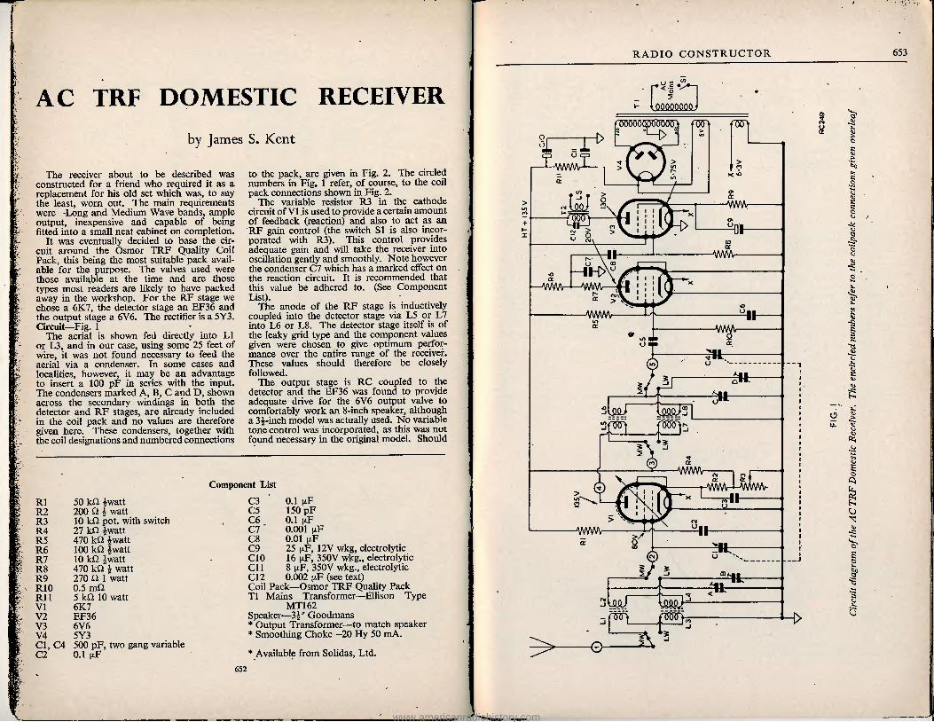
AC TRF DOMESTIC RECEIVER
by James S. Kent
The receiver about to be described was constructed for a friend who required it as a replacement for his old set which was, to say the least, worn out. The main requirements were—Long and Medium Wave bands, ample output, inexpensive and capable of being fitted into a small neat cabinet on completion.
It was eventually decided to base the cir- cuit around the Osmor TRF Quality Coil Pack, this being the most suitable pack avail- able for the purpose. The valves used were those available at the time and are those types most readers are likely to have packed away in the workshop. For the RF stage we chose a 6K7, the detector stage an EF36 and the output stage a 6V6. The rectifier is a 5Y3. Circuit—Fig. 1
The aerial is shown fed directly into LI or L3, and in our case, using some 25 feet of wire, it was not found necessary to feed the aerial via a condenser. In some cases and localities, however, it may be an advantage to insert a 100 pF in series with the input. The condensers marked A, B, C and D, shown across the secondary windings in both the detector and RF stages, are already included in the coil pack and no values are therefore given here. These condensers, together with the coil designations and numbered connections
to the pack, are given in Fig. 2. The circled numbers in Fig. 1 refer, of course, to the coil pack connections shown in Fig. 2.
The variable resistor R3 in the cathode circuit of VI is used to provide a certain amount of feedback (reaction) and also to act as an RF gain control (the switch SI is also incor- porated with R3). This control provides adequate gain and will take the receiver into oscillation gently and smoothly. Note however the condenser C7 which has a marked effect on the reaction circuit. It is recommended that this value be adhered to. (See Component List).
The anode of the RF stage is inductively coupled into the detector stage via L5 or L7 into L6 or L8. The detector stage itself is of the leaky grid type and the component values given were chosen to give optimum perfor- mance over the entire range of the receiver. These values should therefore be closely followed.
The output stage is RC coupled to the detector and the EF36 was found to provide adequate drive for the 6V6 output valve to comfortably work an 8-inch speaker, although a 34-inch model was actually used. No variable tone control was incorporated, as this was not found necessary in the original model. Should
Component List
Rl 50 kO 4watt R2 200 Cl 4 watt R3 10 kQ pot. with switch R4 27 kO 4watt R5 470 kO 4watt R6 100 kO Iwatt R7 10 kO 4watt R8 470 ktl 4 watt R9 270 O 1 watt RIO 0.5 mfl Rl I 5 kO 10 watt VI 6K7 V2 EF36 V3 6V6 V4 5Y3 Cl, C4 500 pF, two gang variable C2 0.1 nF
C3 0.1 |xF C5 150 pF C6 0.1 |xF C7 0.001 gF C8 0.01 MF C9 25 ixF, 12V wkg, electrolytic C10 16 gF, 350V wkg., electrolytic Cll 8 u.F, 350V wkg., electrolytic C12 0.002 uF (see text) Coil Pack—Osmor TRF Quality Pack T1 Mains Transformer—Ellison Type
MT162 Speaker—34" Goodmans * Output Transformer—to match speaker * Smoothing Choke—20 Hy 50 mA.
* Available from Solidas, Ltd. 652
RADIO CONSTRUCTOR 653
< =
■m
I 1 U i WWW I r
>< <0
WM \
01
II wwv
g —lH>v —WWV VW\A—
s 5
VWWV
m
•tt
3U1J
A/WWV "s I si MAMrMMMAr
th
II AAAA/w >/
II
y poo>A
©
www.americanradiohistory.com
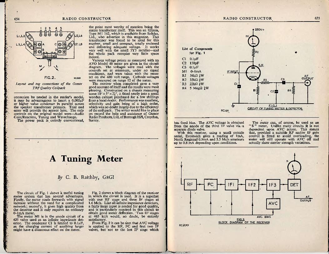
654 RADIO CONSTRUCTOR
12 3 4 5
LI.LZ
L3,L4 § ©
0]( B D CV C\ /? ,[o
L5}L6
L7, U8
FIG, 2. RC.2SO
Layout and tag connections of the Osmor TRF Quality Coilpack
correction be needed in the reader's model, it may be advantageous to insert a O.OCGjiF or higher value condenser in parallel across the speaker transformer primary. Trial and error will provide the answer here. The only controls on the original model were—Audio Gain/Reaction, Tuning and Wavechange.
The power pack is entirely conventional.
the point most worthy of mention being the mains transformer itself. This was an Ellison, Type MT 162, which is available from Solidas, Ltd., who advertise in this magazine. This transformer was found to be ideal for this receiver, small and compact, totally enclosed and delivering adequate voltage. It works very well with the small 5Y3 rectifier—and the whole pack occupies very little space indeed.
Various voltage points as measured with an AVO Model 40 meter are given in the circuit diagram. The voltages were read with the controls set at minimum, under no signal conditions, and were taken with the meter set on the 480 volt range. Cathode voltages were measured on range 12 of the meter.
The receiver when completed gave a very good account of itself and the results were most pleasing. Constructed on a chassis measuring some 10" x 5" x2i", it fitted neatly into a small wooden cabinet purchased for a few shillings from a local dealer. Performance was exceUent, selectivity and gain being of a high order, which was no doubt largely due to the efficiency of the coil pack. The writer would like to place on record the help and assistance of Osmor Radio Products, Ltd, of Borough Hill, Croydon, Surrey.
A Tuning Meter
By C. B. Raithby, G8G1
The circuit of Fig. 1 shows a useful tuning meter system that has several advantages. Firstly, the meter reads forwards with signal increase without the need for a complicated network; second'y, it gives high quality from the detector and it only requires an ordinary 0-1 mA meter.
The meter Ml is in the anode circuit of a 6J5 valve used as an infinite impedance det- ector. The condenser C1 is limited to 0.1 uF, as the charging current of anything larger might have a disastrous effect on the meter.
Fig. 2 shows a block diagram of the receiver in which the circuit is used. It is a superhet with one RF stage and three IF stages at 1.6 Mc/s. Like all infinite impedance detectors, a fairly large input is needed for good quality, and is particularly required in this circuit to obtain good meter deflection. Two IF stages at 465 kc/s would, no doubt, be entirely satisfactory.
From Fig. 2 it can be seen that AVC voltage is applied to the RF, FC and first two IF valves, but not to the last IF stage which
RADIO CONSTRUCTOR 655
' 250V+
List of Components for Fig. 1
C1 0.1 [rF C2 150pF C3 0.1 pF Ml 0-1 mA R1 56kn /W R2 33kU JW R3 22kQ iW R4 5 MegD JW
92
6J5
IF INP^IT AF
OUTPUT C3 R3 0
R4 C2
PC 199 FIG. I
CIRCUIT OF TUNING METER & DFTFCTOR
has fixed bias. The AVC voltage is obtained from the anode of the third IF valve via a separate diode valve.
With this receiver, using a small outside aerial, Droitwich gives a reading of 1mA, North Regional 0.9mA and 3.5 Mc/s amateurs up to 0.8 mA depending upon conditions.
The meter can, of course, be used as an " S " meter. Unlike many circuits it is not dependent upon AVC action. This means that, provided a suitable RF and/or IF gain control is fitted to avoid overloading, the meter will still operate with AVC off and actually show carrier strength variations.
1
RF FC IF2 1F3 DET
AF
AVC OUTPUT
AVC BIAS FIG.2
BLOCK DIAGRAM OF THE RECEIVER RC200
www.americanradiohistory.com

656 RADIO CONSTRUCTOR
Trade News
.
Those readers who are following the series of articles on Radio Control Equipment will be interested in the smart craft shown in the illustration. The " Wavemaster" Model Cabin Cruiser, as it is called, is particularly suited to the radio enthusiast, who as a general rule is not skilled in the art of model making, for it is supplied as a complete kit of ready shaped parts which need only trimming and fitting together. The only tools and materials required for its construction are a hammer, knife, small file, glasspaper and glue—nails are provided in the kit.
The boat itself is of substantial size, having a length of 34", beam of 11", and a freeboard of 4". This provides ample room for power plant and radio control gear, without being too large for easy transport. The makers recommend an internal combustion engine of from 3.5 to 8 cc, but there is no reason why an electric motor could not be substituted, speed thereby being sacrificed in favour of more complete control, e.g., two forward speeds, reverse and stop positions being quite easily arranged.
The kit is manufactured by Hammersmith Model Makers Ltd., 92 Holland Park Avenue, London, and is supplied with full-size plans and easy-to-follow instructions. The retail price is £3 Od.
Further information and advice on suitable power plants and radio control equipment for the " Wavemaster," and also about the kit itself, is available on request from Mr. J. Carter, 101 High Street, Harlesden, London, N.W.10., who kindly sent us the above informa- tion.
Allen Components Ltd., Lower Richmond Road, Richmond, Surrey. This firm has sub- mitted to us for test with the " Magna-View " samples of their new Castellated Yokes which employ Mullard Ferrox-cube foundations.
These represent probably the most advanced method of securing rectfiinear scanning with- out the so often attendant de-focusing at the picture edges.
Formed geometrically around the Ferrox- cube formers, the windings are placed into slots moulded in them and so accurately produce a correctly shaped picture.
This firm must have spent considerable research on these coils to have overcome the often present drawbacks with castellated yokes, that is excessive frame scan, restricted line output, with oscillation effects present on the left-hand side. The coils we had behaved perfectly on test.
RADIO CONSTRUCTOR 657
Trade News—continued
Mullard Ltd. HAVE VERY KINDLY CONSENTED TO EXHIBIT ON THEIR STAND AT THE FORTHCOMING NAT- IONAL RADIO SHOW A COMPLETE CHASSIS OF THE " UNIVERSAL" LARGE SCREEN AC/DC TELEVISOR NOW CURRENTLY BEING DESCRIBED IN THIS MAGAZINE. READERS WHO ARE INTENDING TO VISIT THIS EXHIBI- TION SHOULD CERTAINLY MAKE A POINT OF SEEING THIS EXCELLENT RECEIVER.
The General Electric Co. Ltd., announce a new low noise voltage amphfying perrode in the Osram Z729. This is a low microphony, low hum, voltage amplifying pentode of all- glass construction on a B9A (Noval) base. A stage gain of the order of 180 is obtainable.
Also released is the 305 barretter, which is a hydrogen-filled current regulator designed primarily t or the protection of series-connected television receiver heater circuits using 0.3A valves. This barretter ensures that the current is maintained within 5% of its nominal value of 0.3A for a voltage drop across the barretter
of 40-90 volts. The tapped resistor for the HT circuit will normally still be required.
Stop Press. See advertisement in this issue Radio Servicing Company, address is now 82 South Baling Road, London W5.
Metal Rectifiers. 250V 60mA H/W 6/6; 250V 250mA H/W 12/6; i2-24V JA H/W 4/6; I2/24V 3A F/W 12/-; I2-24V 4A F/W 14/-. Polystyrene B7G Holder with Can, set of 4, 6/-. Earphones. 4000^ 12/6 per pair. 1T4, IRS, ISS, 3S4, set of 4. 32/-. Linecord. .3A. 3-way 60-70Q p. foot, 1/9 per yard. Co-Ax Cable. 70-80Q per foot, I/- per yard. Radio Cabinet. Size 12 x 7 x 5 inch in Walnut (wood) or brown (Bakelite) complete with punched chassis, Dial (Med. and Longwave) backplate, drum drive and pointer, £1/7/6. Cable & Wire Stripper. Ideal Tool for home and Workshop. Price 5/6. Hundreds of Bargains in Radio and TV Com- ponents. Send for List. Callers Welcome. Please add Postage.
JACKSON'S RADIO SUPPLIES 163 EDGWARE ROAD LONDON W.2
DONT MISS THIS HANDBOOK!
o A T A B O O *
U
INDISPENSABLE TO
THE AMATEUR
TRANSMITTER
AND LISTENER
It contains all those details of informa- tion which the transmitter and SWL constantly require. . Right up-to-the-minute Amateur Band Prefix lists, both alphabetically and by country, Zone Boundaries, Call Areas, Mileage Tables, QSL Bureaux, "Q" and "Z" Codes, WWV Skeds, and much other information, as well as a selection of maps of DX areas.
Price 2/6, postage 2d.
DATA PUBLICATIONS 57 NAIDA VALE LONDON W9
www.americanradiohistory.com

- if ijou look for BIG
You'll be amazed at the vast improvement that arises from the use of OSMOR "Q" Range Coils. No wonder our customers are enthusiastic ! These "mighty marvels in minature" are super-selective and sensitive to a degree they never dreamed possible. And we guarantee them—they're the outcome of scientific research plus the highest technical ability. EACH Note these "plus" points —
% Only I in. high. # Fitted tags for easy connection. 0 Packed in damp-proof cartons. 0 Low loss Polystyrene formers. % Variable iron dust cores
COILPACKS. Now at new lower prices!—A full range is available for Superhet and T.R.F. Mains or Battery. Size only Ifin. high x 3^in, wide x 2iin. Ideal for reliable construction of new sets, also for conversion of the 21 RECEIVER TR.1196, TYPE 18. WARTIME UTILITY and others. Aligned and tested, with full circuits, etc. Fully descriptive leaflets available. We keep stocks of many radio components for use in published circuits, including: "RADIO CONSTRUCTOR" TRII96 Conversion; A.C. T.R.F. Domestic Receiver. "PRACTICAL WIRELESS" 3-Speed Autogram; Modern l-valver; A.C. Band-pass 3; RII55 Converter; Modern High Power Amplifier-2; Attache Case Portable; Beginners Superhet. "WIRELESS WORLD" No Compromise T.R.F. Tuner. Midget Mains Receiver. Sensitive 2-Valve Receiver. Television Converter.
L 4
L.
Various types of OSMOR Dials, Chassis, I.F.s, Speakers, Transformers, etc., to match our coils and coilpacks are all listed.
m/
Send 5d. (stamps) for CIRCUITS and full lists of coils, coilpacks and radio components.
Dear Reader, We can't mention all our products here, but
shall be glad to receive your enquiries for Chassis, Tuning Condensers, Switches, Volume Con- trols and all other Radio Components. If it's top quality components and a speedy, courteous service you are looking for—try Osmor. We really
shall do our best for you.
radio product? ltd
(Dept. R.C.I I) BRIDGE VIEW WORKS, BOROUGH HILL CROYDON, SURREY Telephone: Croydon 5148/9
ft
EMI INSTITUTES
EXPERIMENTAL KIT
LEARN THE PRACTICAL A specially prepared set of radio parts from which we teach you, in your own home, the working of fundamental electronic circuits and bring you easily to the point when you can construct and service a radio set. Whether you are a student for an examina- tion, starting a new hobby, intent upon a career in industry, or running your own business—this Course is intended for YOU—and may be yours at a very moderate cost. Available on Easy Terms. WE TEACH YOU: Basic Electronic Circuits (Amplifiers, Oscillators, Power Units, etc.) Complete Radio Receiver Testing & Servicing!
POST IMMEDIATELY FOR FREE DETAILS I TO: E.M.I. INSTITUTES Dept. 179 X I Grove Park Rd., Chiswick, London, W.4 Name Address
wAY
INSTITUTES Associated with
MARGONIPHONE COLUMBIA i
HMV His Master's Voice
:.c. 12
ELECTROLYTIC CONDENSERS 8 mfd. 450 v.w. . 8 mfd. 500 v.w. . 16 mfd. 350 v.w.. 16 mfd. 500 v.w.. 32 mfd. 500 v.w,. 50 mfd. 350 v.w.. 60 mfd. 350 v.w.. 250 mfd. 350 v.w. 8+8 mfd. 450 v.w. 8+16 mfd. 500 v.w. . 12+12 mfd. 350 v.w. .
2/3 2/11 2/6 3/6 4/11 3/11 3/11 4/11 4/6 4/11 3/6
16+16 mfd. 500 v.w. . 16 + 32 mfd. 450 v.w. . 32+100 mfd. 450 v.w. 60+ 100 mfd. 350 v.w.
BIAS 25 mfd. 25 v.w. . 50 mfd. 12 v.w. . 50 mfd. 50 v.w. . 75 mfd. 12 v.w. .
. 4/6 . 5/11
. 7/6
. 9/6
1/6 1/6 1/6 I/-
ALL BRAND NEW AND GUARANTEED (NOT EX-GOVT.) All other types. Paper, Tubular, Waxed, etc., in stock
SPECIAL C.R.T. OFFER
Brand new and unused 12/n ion trap cathode ray tubes. 6.3 volt heater, 7-9 Kv. E.H.T. 35 mm. neck. Black and white picture. Screen has very slight blemishes £11/19/6 Perfect . . .£12/19/6 Carriage and insurance 15/- per tube extra.
GERMANIUM CRYSTAL DIODES
2/3 each ANTENNA ROD
SECTIONS Steel, sprayed khaki. Each rod 12/n long, iin diam. Any number can be fitted together. 2/6 per doz. 6/- three doz.
POST FREE. VCR97 C.R. TUBES
New unused. 40/- Carriage 5/-.
EHT Transformer*'' For VCR97. 45/-. SCREEN ENLARGER For VCR97. Filter type, 17/6. Postage 2/6.
E.H.T. Condensers .1 mfd. 3Kv.. . . 3/6 .1 mfd. 2.5 Kv. . . 2/6
MICROPHONE STANDS Table model. 2-section
chrome plated. Crackle finish base . . . 17/6 Floor model. 2-section. Brass, heavily chrome plated 69/6
Carriage 2/6 extra SOLON
SOLDERING IRONS 220-250 volts. Latest model in- strument iron . . 19/8 Standard model . 19/-
SPECIAL. BRAND NEW T.C.C. T.V. CONDENSERS 32+100 mfd. 450 v.w. Type CE15PE . . . . Price 7/6 .04 mfd. I2.5Kv. Type CP59VO Price 7/6
9 ■X xv
LARGE SCREEN T.V. Every component in stock for the Magnaview, Tele King,Viewmaster and Universal television receivers, including all cathode ray tubes and valves.
9 INCH TABLE T.V. CABINETS
Medium shade mahogany fin- ish. Complete with back, safety glass, speaker-fret. Internal dimensions: I9|/n high, 16/n wide, 14/n deep. LASKY'S PRICE 39/6. Car- riage 7/6 extra. Adaptor frame available for 6/n c.r. tubes. The aperture can easily be enlarged for 12 or 14/n c.r. tubes.
A.C. MAINS GRAM MOTORS
For use on 200-250 volts, 50 c.p.s. Rim and belt drive type. 9/6 each. MANY USES.
PORTABLE TAPE RECORDER CABINETS
Strong wood construction, finished in attractive cream covering,with carrying handle and two chrome plated locks fitted. Hinged lid. Internal dimensions: 15/n long, 10/n wide, 7/n high. Soiled con- dition. LASKY'S PRICE 25/-. Carriage 5/- extra.
DINGHY AERIALS WITH REFLECTORS
Umbrella type, with wire mesh reflector. Complete with setting up instructions. Mast not supplied. LASKY'S PRICE 7/6. Post 1/6. TANNOY PRESSURE
UNITS 10 watts. 7.5-ohms imped- ance. Last few only. Price Reduced to 59/6. Carriage 3 /6 extra.
I.F. TRANSFORMERS Midget. 465Kc/s. Iron dust cores. In can size: I x li x 2+'n. high. 12/6 pair. Wearite type 500, 450-470 Kc/s. Dust cored compression trimmer tuned. In can, size: 1? /n square x 3j/n high. 12/6 pair. Wearite type 550. 445-520 K/cs. Permeability tuned. In can, size as for 500 type. 12/6 pair. C.R.T. Rear neck protectors.
2/6. R.II32A RECEIVERS
With all valves. Brand New . . 79/6 Store Soiled . . 59/6
Carriage 10/- extra. AMPLIFIERS
4-Watt Model. Ex-Govern- ment. Complete with 10 valves: 2 25L6, I 6H6, I 25Z6, 6 6SK7. For operation on 110 volts A.C./D.C. Bal- ance and push-pull. High, medium and low impedance inputs, A.G.C., etc. LASKY'S PRICE £5/19/6 complete. No circuits available. Carriage 10/- per unit extra.
GARRARD RECORD PLAYERS
For 6 and 12 v. operation. Complete with magnetic pick-up, and volume control. In metal cabinet size 17/n x 14/n x Win. Very limited quantity. LASKY'S PRICE £5/19/6. CcirHq^e 10/- extra.
CATHODE RAY TUBES MASKS New aspect ratio.
9/n 5/- 9/n cream ... 7/-
10/n Double D . . 7/6 12/n 15/- 12/n Flat face . . 15/- 12/n Old ratio . . 9/6 Kin Rect. . . .21/- I6/n Double D . . 31/6 17/n Rect. . . . 25/- 12/n Soiled . . . 7/6 12/n Soiled. Cream, with safety glass . 11/6 12/n Soiled. Black, with safety glass . 8/6
15 INCH CATHODE RAY TUBE MASKS No. I. Cream rubber. Latest aspect ratio. Over- all dimensions: 17/n wide, 13/n high. Price 17/6. Postage 2/- extra. No. 2 Plastic, incor- porating gold finish tube escutcheon, and dark screen filter. Latest as- pect ratio. Overall di- mentions 15/n wide, 12/n high. Price 21/-. Post- age 2/- extra.
ARMOUR PLATE GLASS
15/n Actual size, I8|/n x 19+n x |/n 7/11. 12/n Actual size, 13/nx IO+'nx iin 4/-. 9/n Actual size, 9/n x 8/n x iin. 3/-.
DARK SCREEN FILTERS
(LATEST TINT) 18 x 14+n . . . 25/- I4ixl2i/n. . . 19/6 I3f x I l/n . . .14/11
PERSPEX 13+n x IO+'n x iin. Natural shade, slightly marked. 5/11 per piece.
I \ i li V " i U A 11 III (Harrow Road) Ltd. 370 HARROW R L I } ll I 13 UilUlU PADDINGTON LONDON W9
(Opposite Paddington Hospital) Telephones CUNningham 1979 and 7214. All Departments. Hours Mon. to Sat. 9.30 a.m. to 6 p.m., Thurs. half day I p.m.
MAIN ORDER & DESPATCH DEPARTMENTS 485/487 Harrow Road Paddington London W 10 Terms Pro Forma, Cash with Order, or C.O.D. on post items only. Postage and packing on orders value £1
I/- extra, £5-2/- extra, £10—3/6 extra. Over £10 carriage free. All goods fully insured in transit.
www.americanradiohistory.com
660 RADIO CONSTRUCTOR
A D 30/- 21/- 40/- 42/- 39/6 43/- 21/- 21/- 15/- 16/- 7/6 7/6 7/6 7/6
31 - 35/- 40/6
COMPONENTS FOR 5 CHANNEL
LARGE SCREEN TELEVISOR COMPONENTS BY ALLEN (A) OR
DENCO (CLACTON) LTD. (D)
Auto Transformer . Main Choke Line/Scan Transformer . Deflector Coils Frame Output Transformer Frame Blocking Transformer Width Control Linearity Control . Focus Control . Set of Coils and Chokes T.C.C. Condensers Morganite and Colvern Potentiometers Resistors Valves Cathode Ray Tubes Chassis—Power Pack 5/-, Time Base Vision/Sound 17/6
POSTAGE AND PACKING EXTRA C.W.O. or C.O.D.
TELE-RADIO (1943) LIMITED 189 EDGWARE ROAD LONDON W2
Telephone PAD 4455/6 Shop Hours
Monday-Saturday 9 a.m.-6 p.m. Thursday 9 a.m.-l p.m.
17/6,
KENDALL
AND
MOUSLEY
Manufacturers of
Laboratory Equipment
Chassis and Instrument Cases
also suppliers of
B.V.A. VALVES RADIO COMPONENTS
TV COMPONENTS
99 DUDLEY PORT
UPTON • STAFFORDiHIRE
IKOPATENTS
LTD. Managing Director
E. G. O. ANDERSON
Consultants
• RADIO
• TELEVISION
• ELECTRONICS
ij CRISP ROAD W6 RIVERSIDE 2678
Rotary Converters by Hoover, 6v. in, 200v. 60m.a D.C. Ideal for car radios, etc., etc. Price 17/6 Postage 2/6.
Telephone Hand Sets P.S. ^pe 10/6 Postagel/6, Mumetal Screens. VCR97 Price 8/6. Postage I/-. Mine Detectors. Consisting of 2v. amplifier,
complete with valves, satchel, search coils, head- phones, etc. Ideal for locating metals, hidden treasure, etc. 45/-. Carriage 3/6.
Keying Relays. As used in 1154 Transmitter. These contain 5 sets of change over contacts and 2 sets of make contacts and have two 24v. coils. Brand new in makers carton. Price 7,6. Post I /3.
Large Magnets. As taken from magnetron units weight approx. 91b. Will lift up to 30—401b. Price 30/-. Postage 2/6.
Hand Switches. Press on, double pole, bakelite case, with 4ft Sin 3-way cable. Price 1/6. Post I Id.
Small Chassis. 4^''x8^xl J". Drilled for 3 valves. Volume control switch, etc. Price 2/6. Post lid.
OH MITE VARIABLE RESISTORS. Vitreous. 80 ohm. la. Price 716. Post |/-.
Modulator Units Type 64. I0DB/956. Cha'sis less valves and relays. Weight about 281b. Price 15/6. Carriage 7/6.
Banks of 20 Relay Coils. With armature, but no contacts. 10 relays 30 ohms, and 10 relays 100 ohms. Price 7/6. Postage 2/-.
Large new list, No. 10, now available Price 6d. inland. I/6 overseas Air Mail.
A. T. SALLIS 93 NORTH ROAD BRIGHTON SUSSEX
Telephone BRIGHTON 25806
RADIO CONSTRUCTOR 661
SMALL ADVERTISEMENTS
Readers' small advertisements will be accepted at 2d per word, minimum charge 2/-. Trade advertisements will be accepted at 6d per word, minimum charge 6/-. If a Box Number is required, an additional charge of 1/- will be made. Terms: Cash with order. All copy must be in band by the 12th of the month for insertion in the following month's issue.
PREMIER model Tape Recorder for sale complete with Ronette ball-type crystal microphone, spares, record and erase heads, 2 valves and oscillator coil. £25 or near offer. Anersley, 46 Lawrence Avenue, London, E.12.
LARGE Console Cabinet, suitable television £8; 12-valve chassis £10; Radio magazines. SAE to L. Marks, 14 Avenue Road, Kingston, Surrey.
ADVANCE Signal Generator Model E2 for sale. New, unused and perfect. Complete with accessories and instructions. Offers above £20. Rice, 68 Vernon Drive, Stanmore, Middx.
TEST Set 73 converted scope £9; R1132 complete 65/-; Atkins Valve Tester £9. Carriage paid. Bryant, 26 West Street, Cromer, Norfolk.
MODIFIED 1355 for Alexandra Palace and RF25 for sale. Good picture. All wave coil pack, new. The lot £2/5. Box No. C129.
' ELECTRO DYNAMIC " Converter 230 DC, 230/250 AC, soundproof case, designed for Television. As new. £18. Beal, 1 St. Helens Road, Sheerness.
FERRANTI T12/46 Tube with Mask and Focus Ring NBI09/1, £6/10. Newnes Radio and Television £4. Burgoyne Solder Gun, less bits, £1/10. Box No. C131.
AERIALITE 63A Holme Moss aerial for sale, complete, £4 carriage free. K. Murray, 8 Manor Road, Long- benton, Newcastle-upon-Tyne, 7.
PREMIER Magnetic 9" TV, working, complete, spare set valves, no cabinet, £18. Also over 200 various valves, new and Ex-Govt; Radio and TV components. SAE for details, S.W. London. Box No. C132.
12-INCH static tube with mounting for sale, also time base with valves including sync separator. Best offer over £5. H. G. Weston, 16 Pitfold Road, Lee, S.E.12. Phone Lee Green 5702.
EDDYSTONE S640 for sale, choice of two, mint con- dition, matching speakers, two German receivers and spares, model 18 receiver. Offers, buyer collects. Fawkes, St. Chloe Green, Amberley, Stroud, Glos.
{continued on page 663)
HENRY'S 5 HARROW ROAD LONDON W2
Open Mon. to Sat. 9—5.30 (Thurs. I p.m.) Telephone PAD 1008/9 and 0401
SPECIAL VALVE OFFER Ten EF50 Brand New (Ex-Units) 55/- set. SET OF 5 MAINS VALVES 6K8CT, 6K7GT, 6Q7G, 5Z4, 6V6G or KT6I, at 42/6 Set. SET 5 AC/DC VALVES 6K8GT, 6K7G, 6Q7G. 25A6G, 25Z6G at 42/6 Set. SET 5 AC/DC VALVES 6A7G, 6D6, 6C6, 43, 25Z5 at 42/6 Set. SET 5 AC/DC VALVES I2K8GT, I2K7GT, I2Q7GT, 35Z4GT, 35L6GT or 50L6GT at 42/6 Set. SET 5 AC/DC VALVES I2SA7GT, I2SK7GT, I2S07GT, or I2SR7GT, 35Z4GT, 35L6GT or 50L6GT at 42/6 Set. SET OF 4 BATTERY MINIATURE l.4v. VALVES IRS, IS5, IT4, 1S4 or (3S4 or 3V4) at 32/6 Set. SET OF BATTERY VALVES 2 volt MAZDA TYPES TP25, HL23/DD, VP23, PEN25 or QP25 at 27/6 Set, COMPLETE SET OF 10 SPECIFIED VALVES FOR "PRACTICAL TELEVISION" PERSONAL REC. 5- 6AM6, 2- 6AK5, I- EA50, I- 6J6, I- 6C4 and 3BP1 C/R Tube in case at £5.12.6 Set. L.T. RECT'S 6v. I amp G.E.C. ... 4/- I2v. 2^ amp. Westinghouse 12/6 I2v. 4 amp. S.T.C. ... ... '7/6 I2v. 8 amp. S.T.C 32/6 S.T.C. RECT'S. E.H.T. K3/25 650v. I m/a 4/7 K3/40 lOOOv. I m/a 6/- K3/I00 8,500v. 1 m/a 14/8 K3/200 I0,500v. I m/a 26/- H.T. RECT'S S.T.C. 150v. 120 m/a 4/6 S.T.C. 250y. 250 m/a 18/- G.E.C. I m/a Meter Rect. ... ... ... ... 11/6 RECEIVER RI355. As specified for Inexpensive Television. Complete with 8 valves VR65 and I each 5U4G, VUI20, VR92. Only 55/- carriage 7/6. Brand new in original case. RF24 25/-, RF25 25/-, RF26 59/6, RF27 59/6. CATHODE RAY TUBES VCR97. Guaranteed full picture 40/-, carriage 2/-. VCR5I7. Guaranteed full picture 40/-, with Mu-Metal 3BPI Suitable for 'scopes 25/-, carriage 3/-. Screen, Mu-Metal Screens 10/-. 6" Enlargers 17/6. PYE 45 Mc/s STRIP. Type 3583 Units. Size I5A'x8*x2''. Complete with 45 mc/s Pye Strip, 12 valves, 10 EF50, EB34 and EA50, volume controls and hosts of Resistors and Condensers. Sound and vision can be incorporated on this chassis with minimum space. New condition. Modification data supplied. Price £5, carriage paid. INDICATOR UNIT TYPE I82A. This unit contains VCR5I7 Cathode Ray 6" Tube, complete with Mu-metal screen, 3 EF50, 4 SP6I and I 5U4G valves, 9 wire-wound volume controls and quantity of Resistors and Condensers. Suitable either for basis of Television (full picture guaran- teed) or Oscilloscope. Offered BRAND NEW (less relay) in original packing case at 79/6. Plus 7/6 carriage. VCR5I7C BLUE AND WHITE 64in. TUBE This Tube replaces the VCR97 and VCR5I7 without alteration and gives a full Blue and White picture. BRAND NEW in original crates, 45/-, plus 2/- carriage. "WEYMOUTH" 3-WAVE BAND COIL PACKS Short, Med. and Long with Gram. Switch. Brand New Miniature type complete with circuit, 19/6. P.P. 1/6 Absolute bargain.
SEND 3d. FOR 28-PAGE CATALOGUE
www.americanradiohistory.com

662 RADIO CONSTRUCTOR
Coronation QSL's why not send a distinctive QSL this year ?
Special designs to celebrate Coronation.Year, available from G6MN who has supplied 'special* QSL's for discriminating
users all over the world. Attractive " Coronation-1953 " designs now available from G6MN Castlemount Worksop Notts
VALVES — OVER 3,000 IN STOCK I2AT7, 6BW6, 6CH6. 6SN7, 807, 6V6, 9/-. EF9I, 6AM6. EC9I, EL9I, 6J6, 6SJ7, 12AX7, 7/6, 6C4, 6J5. 6N7, 6J7,
EF92, EAC9I 6/-. SKILLMAN FRANCHISE STREET WEYMOUTH
PHILIPS I2v. MOTORADIOS Brand new in makers cartons and fully covered by makers guarantee. Leaflet on request. List price £34.4.6. Limited quantity only offered while they last at only £17.17.0 plus 10/- carriage. Pye plugs & sockets 7/6 doz. prs. 25pfd ceramic air spaced trimmers 5/6 doz. .Olmfd 500v mica conds. 3/6 doz. Eddystone flexible couplers l/6ea. 15/-doz. Double circ. jack plugs & sockets 2/6 pr. 24/- doz. 4-Bank Yaxley sw. ea. bank 2p4w. (Total 8P4W) 4/6 ea. 45/- doz.
Please add post/packing J. T. ANGLIN
160 CLEETHORPE ROAD GRIMSBY LINCS Telephone 56315
VALVES, NEW TESTED AND GUARANTEED
IRS 7/9 6F6g 8/6 6SA7 7'6 6V6g 8/6 IS5 7/9 6FI2 7/6 6SG7 6/6 6V6gt 8/6 IT4 7/9 6G6 5/9 6SK7 6/9 8D3 7/6 IS4 7/9 6J5g 4/6 6SN7 8/6 I2AT7 7/9 3S4 7/9 6K7g 4/6 6SQ7 7/6 I2AX7 5/9 3V4 7/9 6K7 6/6 6X4 8/6 57 6/9 5U4g 8/6 6K8gt 8/6 6X5 7/6 954 21- 5Z4g 8/9 6K8g 8/9 7C7 7/9 2C34 2/- 6AM6 7/6 6Q7g 8/9 7H7 6/9 EB9I 6/6 MATCHED PAIRS 6V6g and gt 17/-; 6F6G 17/-; KT66 21/-; 807 15/6; 6G6 12/-; 6J5g 9/6 per pair
P. ond P. 6d per valve R. COOPER
32 SOUTH END CROYDON SURREY Telephone CROydon 9186
REP HIGH GAIN DUAL RANGE COIL WITH REACTION
COMPLETE WITH
2 BATTERY AND
2 MAINS CIRCUITS
PRICE 4/- POST 3d. (Trade Supplied)
Radio Experimental Products Ltd. 33 MUCH PARK STREET
COVENTRY
ADCOLA (Regd. Trade Mark)
SOLDERING INSTRUMENTS
Reg. Design No. 860302 (British, U.S. and Foreign Patents)
Designed for wireless assembly and Maintenance Supplied for all volt ranges from 6/7v to 230/250v.
3/16* Dia. Bit Standard Model 25/6 Sole Manufacturers ADCOLA PRODUCTS LTD.
Safes Office and Works: Cranmer Court. Clapham High St. London SW4 (MAC 4272)
ROTARY CONVERTERS 12V DC to 200V DC 50 MA £1 10 0 24V DC to 230V AC 150 VA £6 0 0
S.A.E. FOR MODEL RAILWAYS EQUIPMENT
PRE-WAR VALVES. TRANSFORMERS
Lawrence Frankel MAIL ORDER
134 Cranley Gardens London N 10 Telephone TUDor 1404
SAMSONS SURPLUS STORES WE STILL HAVE ONE OF THE LARGEST STOCKS OF EX COYT. COMPONENTS AND ELECTRONIC EQUIPMENT IN ENGLAND. ALL ENQUIRIES WELCOME. THE MONTHS SPECIAL OFFER: ADMIRALTY INTEGRATORS TYPE ASS I WITH VERY FINE CALVO MOVEMENT 52/6. ELECTRO-MAG- NETIC COUNTERS 500 OHM COIL, COUNTING TO 9999. 24v-50v D.C. 10/6.
POST FREE 169-171 Edgware Road, London,
PAD 7851 W.2. 125 Tottenham Court Road
London, W.I. EUS 49S2 : orders and enquiries to our Edgware Road branch, please.
This is open all day Saturday.
Special Offer Manufacturers Surplus Parmeko H T Transformers. Prim. I00-250V Sec. 500-0-500V, 400MA 220-0-220V. 30MA. 6.3V 7A. 4V 6A. Completely shrouded. £3/10/- Carr. 5/-. Prim. I00-250V, Sec. 1300-0-1300V, 250MA, Completely shrouded. £3/15/- Carr. 5/-. Heavy Duty Potentiometers by British Electric. Type T. Six inch dia. Pots 1800 ohms .4/.28 Amps, with 3 inch skirted knob 19/6, p.p. 2/-. Four inch dia. Pots 2000 ohms .22 Amps with 3 inch skirted knob. 15/- p.p. 1/6. Parmeko L.F. Chokes 10 Henries 250 M.A. Completely shrouded. 17/6 p.p. 2/-. Aerovox I MFD. 600V WKG. Condensers with clip 1/9. Sprague I MFD 750V WKG. Condensers with clip 1/4 p.p. 6d.
J. HALLETT 19 Upper Richmond Road London SWI5
RADIO CONSTRUCTOR 663
SMALL ADVERTISEMENTS
{continued from page 661)
EDDYSTONE S640 Rx and matching loudspeaker for sale, £20. AVO 1948 type All Wave Oscillator £9; Ex-RAF Test Set Type 73 (see May Radio Constructor] mains driven scope £7; all above in mint condition. Also 1938 Ecko TSC 102 TV Console chassis, power supply and Time Base Chassis and Mazda CRM71 CRT, in perfect order but requires rebuilding of receiver chassis, £10 complete with manufacturers' servicing sheets and circuit diagrams. (Appointments to demon- strate—no dealers please). Nearest offers within 10 days or exchange photographic equipment to D. R. Edwards, 333 Greenwrythe Lane, Carshalton, Surrey.
WANTED to buy, Service Manual for Bush TV22. Box No. C130.
WANTED Practical Wireless February issue 1946. Prowse, 5 Tresluggan Road, St. Budeaux, Plymouth, Devon.
TRADE RADIO CONTROL THAT MODEL. Circuits, methods
(state requirements), and unlimited advice, details 3/6. All information on Wavemaster Kits supplied. Carter, A.M.I.E.T., 101A, High Street, Harlesden, London, N.W.10.
'GLOBE KING" (Regd.) Miniature Single'Valve Receiver gets real Dx. Amateur Radio enthusiasts, should send for free copy of interesting literature and catalogue (enclose stamp for postage). Write to makers: Johnsons (Radio), 46 Friar Street, Wor- cester.
BOOKBINDING. Volumes of Radio Constructor and Radio Amateur fully bound, imitation leather, gold lettering. Is 6d post free. Prices for other publications on application. Jerome Alcock; CHEADLE, Stoke- on-Trent.
FREE CATALOGUE now available. Viewmaster, Tape, Gram, etc., at lowest prices. Swift Radio, 21 Hibbert Road, Harrow, Middlesex.
OAK TYPE SWITCH SERVICE. Multi-Wav Switches made to specification, approx. cost 2/6 Clicker Plate + 2/- per wafer. Box No. C117.
l.P.R.E. PUBLICATIONS. 5,500 Alignment Peaks for superhets 5/9. Sample copy The Practical Radio Engineer 2/-. Membership examination particulars 1/-. Syllabus of TV and radio courses free and post free. Secretary, I.P.R.E., 20 Fairfield Road, London, N.8.
{continued on page 664)
TRANSFORMERS.—Manufactured to our specification and fully guaranteed. Normal Primaries. 425 v.-0-425v. 200 m.a., 6.3 v. 6 a., 6.3 v. 6 a., 5 v. 3a., 0-2-4-6.3 v. 3 a., ONLY 72/6. 425 V.-0-425 v. 200 ma., 6.3 v. 4 a., 6.3 v. 4 a., 5 v. 3 a. ONLY 50/-. 350 v. -0-350 v. 160 ma., 6.3 v. 6 a., 6.3 v. 3 a., 5 v. 3 a. ONLY 42/6. 250 V.-0-250 v 100 ma., 6.3 v. 6 a.. 5 v. 3 a. ONLY 32/6. The above are fully shrouded, upright mounting. Universal Mount- ing 350 v. -0-350 v. 80 ma., 0-4-6.3 v. 4 a., -0-4-5 v. 2 a. ONLY 18/6. Top shrouded, drop through 260 V.-0-260 v. 70 ma., 6.3 v. 3 a., 5 v. 2 a., ONLY 16/6. The following are upright mounting. EHT for VC97 Tube, 2,500 v. 5 ma., 2 .-0-2 v. I.I a., 2 v. -0-2 v. -0-2 v. 2a. ONLY 37/6. EHT 5,500 v. 5ma., 2 v. I a., 2 v. I a. ONLY 72/6. EHT 7,000 v. 5 ma., 4 v. I a. ONLY 82/6. PLEASE ADD 1/6 PER TRANSFORMER POSTAGE. TRANSFORMER, for use on trains, models, etc., giving outputs of 3 v., 4 v., 5 v., 6 v., 8 v., 9 v., 10 v., 12 v., 15 v., 18 v., 20 v., 24 v., 30 v., at 2 amps from normal mains input. ONLY 17/6 (postage I/-). TRANSFORMERS.—Ex. W.D. and Admiralty, built to more than 50 per cent, safety factor, with normal A.C. Mains Primaries. All Brand New and Unused. 300 V.-0-30 v. 200 ma., 5 v. 3 a., 6.3 v. 5 a., C.T., 20 v. 750 ma., 70 v. 100 ma. Weight 12 lb. ONLY 42/6 (postage, etc., 2/6). 330 v. -0-330 v. 100 ma., 4 v. 3 a. Weight 7 lb. ONLY 22/6 (postage 1/6). L.T. 5 v. -0-5 v. 5 a,, 5 v. -0-5 v. 5 a., 5 v. -0-5 v. 5 a. By using combina- tion of windings will give various voltages at high current. Weight 11 lb. ONLY 35/- (postage etc., 2/6). L.T. 6.3 v. 7.7 a., 4.2 v. 2.5 a., 4 v. I a. ONLY 19/6 (postage 1/6). EHT 1,400 v. 2 ma., 520 v. 10 ma., 300 v. 10 ma., 2 v. 1.5 a. ONLY 21/- (postage, 1/6). Cash with order, please, and print name and address clearly. Amounts given for carriage refer to inland only.
U.E.I. CORPORATION The Radio Corner
138 Gray's Inn Rd. LONDON WCI Open until I p.m. Saturdays. We are 2 mins. from High Holborn (Chancery Lane Stn.) and 5 mins, by bus
from King's Cross.
6 VALVE SUPERHET V.H.F. RECEIVER. Six channel switching, tuning 30.5 to 40 mc/s. Receives TV, Fire, Taxis, many British and Con- tinental amateurs, etc. Components include 30 ceramic trimmers, 6 ceramic v/holders, 32 small condensers, 30 resistance, valve cans and covers, etc. All for 7/6. Post 2/6. Also supplied complete with valves at 17/6. Post 2/6. Drawings available for conversion to A.C. or A.C./D.C. operation.
LOUD HAILER. Powerful P.A. system. No valves to break or damage. Metal-clad and weather- proof. Consists of microphone and combined amplifier/speaker. Works off 12 or 24 volts D.C. OUR PRICE £8.17.6, carriage 5/6.
RADIO-GRAM CHASSIS. Three models avail- able. Six wave band at £15.15.0, and two three wave band types, one at £12.12.0, and one at £10.17.6. All are brand new, and have latest valve line-up, gram switch, flywheel tuning and negative feed-back. Carriage 4/6.
RADIO TELEPHONES. Brand new American made walkie-talkie sets. 53-75 mc/s. Visual range. Complete with G.P.O. type handset. Operates either from set of internal batteries, or from a vibrator pack from 12 volt accumulator. PRCIE £9.17.6, less vibrator. OR £18.17.6 a pair. Vibrators 27/6 each. SPECIAL OFFER of £21 for a pair, and two vibrators. Carriage 10/-.
FIXED CONDENSERS. Various values—.005 mfd, 350 VDC; .15 mfd, 350 VDC; .01 mfd, 450 VDC; .001 mfd, 500 VDC; .25 mfd, 350 VDC;
Stamp for complete catalogue C.W.O. or C.O.D.
DUKE & R0MF0RD ROAD 621
Money back guarantee
CO. LONDON EI2
GRA 6677
www.americanradiohistory.com

664 RADIO CONSTRUCTOR
[Z
CLYDESDALE Bargains in
Services Radio and Electronic Equipment "l nent RECEIVER UNIT TYPE 25
Ref. 10P/IL part of the TRI196 equipment. Frequency range, 4.3-6.7 Mcs.
Valves 2/VR53 (EF39), 2/VR56 (EF36). VR55 (EBC33), VR57 (EK32), 2 IFT 460 kcs, plus various microdensers, mic. and output transformers, pots, condensers, resistors etc., connections brought to 10 pin Jones type chassis plug. Circuits are provided in the unit, which is totally enclosed in case, 8^inx6finx6^in. Would make the basis of an All Wave Receiver, required tuning pack and power supply. ASK FOR OQ IL POST No. B/H299 JT/O PAID (Conversion Data ("R.Con.*' Reprint), 1/6) S-440-B V.H.F. TRANSMITTER CHASSIS Partly stripped by the M.O.S., less valves, tuning coils and crystal, but otherwise fairly intact. A fine basis for V.H.F. Tx or 144 Mcs rig. Original frequencies 85-98 Mcs, valve types 3/RK34, 2/6N7, 6V6. Housed in louvred case, finished grey crackle. Dim. 14x8x7ins. ASK FOR I C / POST No. B/H5I7 l3/" PAID
FOR INEXPENSIVE TELEVISION I.F.A.F. Amplifier Unit RI355. ASK FOR CARRIAGE B/E770B Used 22/6 condition PAID
Order direct from: Telephone SOUTH 2706/9
CLYDESDALE 2 BRIDGE STREET GLASGOW C.5
Branches in Scotland England and North Ireland
We are sorry . . .
that we cannot repeat our December publicity offer, but as we are continually being asked for the L.M.S.2 coil-pack together with the specially matched pair of I.F. transformers we are now offering a parcel comprising these items. The price is surprisingly low at £2.7.6 post paid.
L.M.S.2. Miniature Coil Pack 38/6 Post & Pkg. 1/6
♦3 wave band. ♦High quality—outstanding performance. ♦Only 5 wires to solder—one nut to tighten.
Miniature 465Kc. I.F. Transformers 12/- Post & Pkg. I/-
*Specially matched to L.M.S.2. Coil unit. Supplied Separately or in bargain parcel.
5' Loud Speakers brand new nearly ail sold last few 11 /6 post paid
DEAL COMPONENT CO. 105 Evering Road NI6
SMALL ADVERTISEMENTS {continued from page 663)
JOIN THE ISWL. Free services lo members including QSL Bureau, Translation, Technical and Identification depts. Dx certificates, contests and activities for the SWL. Monthly magazine ' MONITOR ' duplicated, containing articles of general interest to the SWL and League member, 10/6 per annum, post free. ISWL HQ. 86 Barrenger Road, London, N.10.
BLUEPRINTS. High Gain 10 Metre Converter, with a de-luxe circuit comprising EF91 RF stage, ECC91 double triode mixer and oscillator, EF92 IF amplifier, with stabilised voltage supply via a 7475. Is Sd post free with full instructions. A.S.W.P., 57 Maida Vale, London, W.9.
FREE ! Brochure giving details of Home Study Train- ing in Radio, Television, and all branches of Electron- ics. Courses for the Hobby Enthusiast or for those aiming at the A.M. Brit.l.R.E. City and Guilds Telecommunications R.T.E.B., and other professional examinations. Train with the College operated by Britain's largest Electronic Organisation. Moderate fees. Write to E.M.I. INSTITUTES, Postal Division, Dept. RC28, 43 Grove Park Road, London, W.4. (Associated with H.M.V.).
METALWORK. All types cabinets, chassis, racks, etc to your own specification. Philpott's Metalworks Ltd. (Dept. R.C.), Chapman Street, Loughborough.
KENDALL AND MOUSLEY. Manufacturers of Laboratory Equipment, chassis and instrument cases, also suppliers of B.V.A. valves. Radio and T.V. com- ponents. 99 Dudley Port, Tipton, Staffs.
Announcement New Service for the Amateur and Experimenter
A stamped addressed envelope will bring you details of the new series of blue-prints of aerial tested circuits, from single valve to six and seven valve super bets. In the near future, kits of parts will be offered, both for the home constructor and the Amateur Transmitter and Receiver. Coming off the drawing board shortly is a Simple Communications Receiver Circuit. Further announcements will be made shortly concerning equip- ment for the T/V home constructor, including wide band pre-amplifiers, etc., at prices which will be right for your pocket. Get your name and address on the files NOW by sending your S.A.E. to J.H.G. Box No. C107.
Miller's " PANL "—the air drying black crackle enamel. From dealers 35 6d jar or direct 45 6d including postage. —8 Kenton Park Crescent, Kenton, Middx.
OSMOR—for efficient coils, coilpacks etc. Send 5d stamp for FREE circuits and lists. Dept. RCC, Osmor Radio Products Ltd., Borough Hill, Croydon, Surrey. Tel. Croydon 5148/9.
AMATEUR STATION RECORD CARDS, 6,,x4,,, best quality card, for recording that QSO and full details of the contact. An invaluable aid to quick reference of stations worked etc., 3/- per 100 from Data Publications, 57 Maida Vale, London, W.9.
RADIO CONSTRUCTOR
YOU CAN RELY ON US" COILS Wearite "P" Coils. All types in stock in- cluding AF.I, RF.I. Price 3/-. Midget I.F. Transform- ers Type 800. 21/- per pair. Standard Type 500/501 (465Kc/s) 20/- pair
HIGH IMPEDANCE
HEADPHONES New Ex-Government Price 12/6 per pair. SCOTCHBOY
TAPE 1200ft Reels 35/- Spare Reels 4/3
COILS Osmor Midget iron- cored "Q" Coils 4/- each. Leaflet on re- quest. Coilpacks Type H.O. 52/-. LM 43/4, MTS 54/2, TRF 43/4 all including Tax. TRIMMERS All new Postage Stamp Ceramic. 4-70pf 8d, 40- lOOpf lOd. 20-l50pf I/- l00-550pf 1/3. LINECORD 3-way -Sa at 60 ohms per foot 6d ft., '2a at 100-ohms per foot 8d ft
The " MAXIMITE" AC/DC SUPERMID6ET SUPERHET — Fu/I P/ons I/- WAVECHANGE SWITCHES Midget rectangular Type, 2P2W 2/6, 2P3W 2/6. Midget Circular Type IPI2W, 2P6W, 3P4W, 4P3W, each 3/6.
Standard Yaxley Type (2 Bank) 2PIIW, 4P5W, 6P3W, 8P4W, 7/6 each.
All above are NEW and have 2' Spindles METAL RECTIFIERS
RMI 5/3, RM2 6/3, RM3 7/-, RM4 21/-, K3/45 8/2, K3/50 8/8, K3/I00 14/8. Westinghouse 36EHTI00 "'9/4, ' - - 29/4, I4A86 20/4, I4D36 II/-, WX6 3/9, WX6 3/9.
T.C.C. CONDENSERS Midget Picopack, Imfd 350v, 2mfd I50v, lOmfd 25v 20mfd I2v, each 2/6. Visconol High Voltage, *001 6kv 6/-, *001 I2kv 10/- •001 I5kv 10/-, -01 6kv 10/-, - I 7kv 20/-. Micadiscs, 500pf 1/6, Type 543, • I 500v I /3, 750v 1/6
ENGRAVED KNOBS 11' WALNUT or IVORY...Volume, Focus, Contrast, Brilliance, Brightness, On/Off, Record/Play, Tone, Bass, Treble, Wavechange, Tuning, Radio/Gram., Brill/OnOff, S.M.L.Gram. All 1/6 each.
RADIO SERVICING COMPANY (Mrc,u^f55WANDSWORTH ROAD LOND™
SOLEDAS LTD 4 PRAED STREET
LONDON W2
DEFINITELY THE CHEAPEST RADIO SHOP IN
TOWN Telephone AMB 4670
324-32 mfd 275V 4/-, 16 mfd 425V-wet-screw fitting, 4/-, 8 mfd 500 screw, 1/6, 8 mfd 600 V/W, screw 2/-, 8 mfd 450 midget, 2/6, 30+30 350, 2/6, 10 mfd paper 600V, 4/-. 4-way Fuse holder, 6d. Continuity tester in nicely polished box can also be used for Morse practice, 5/-; 10 watt push-pull output Trans., 15/-; 4 gang ,0005, 2/6; Slow motion drive with 2* drum, 116. L.T. Trans., 6.3, 2 amps, 7/6. Polythene stand-off insulators, 9d. WX6 W.I. detectors, I /-; L.T. Trans 3V, IA, 2/6; Box of 10, 3.2, 0.2 pilot bulbs, 2/6 Tube neck support fits 9', 12', 15", 2/-. Wire wound pots, I000L2, 500Q, 2/-. Miniature 2 amp plug and socket, I/- pair. L.T. Trans., input II0-250V, output 2-0-2V, 3.3A, or 4V, 6.6A, 12/6. Decca projection
chassis, contains Timebases, Frame and Line circuits. 32/6. Bush All Wave chassis, 5 valve S/Het., less speaker, reconditioned, £6.10.0, has gram, sockets; 5.5 KV EHT Trans, ^with U22' Rectifier, 45/—^ MV4=MH4 4/-; 878A 10/-; Z62 10/-; 807 10/-; Z77 10/-; EF22—7H7 6/-; 3D6 2/6; ILD5 4/-; ARPI2 2/6; VUI I I-VUI33 2/6; 6SS7^6SJ7 5/-; I2Y4 0.3 Rect. 5/-; 6L6M 10/; VT25 5/-; H30 5/-; HHLD6= 6Q7 A.C. 6/-; 6SL7 10/-; 6SN7 10/-; ML4 5/-; TP25 7/6; VR55=EBC33 8/-; VP4I 10/-; SU4G=US2 10/-; 6F6G 8/6; 6C6-6D6 5/-; I2C8 10/-; Y63 7/6; 6G6 6/-; 7DA 10/-; I2SH7 5/-; I2SK7 7/-; II7L7 I0/-;VR56= EF36 6/6; 6AG5 6/-; CUI88 V/Regulator 6/-; VRI37 EC52 4/6; 9D2 4/-; VRII6 4/6. KTZ73-Z66 10/-; 6AK5 I0/-:6SK7 7/-; VRI26=VP4B 10/-; MS/PEN 6/-; SZ4 8/6. Special offer AZ3I less locating pin 6/-; CY3I less locating pin 6/-; KT44 7/6; AC6PEN 6/-; I2SA7 10/-; 5Y5 6/6.
OFSPECIAL INTERESTTO CONSTRUCTORS We always HAVE a large Selection of second-hand Cathode Ray Tubes in stock from 9" to 15". All Tubes can be seen working before purchase. All these Tubes are in tip-top condition.
1 10/th H.P. AC/DC motors, 27/6; I 8/th H.P. DC Motor II0V-I70 volts 15/-; 2 bank 100 PFtrimmers I/-
www.americanradiohistory.com