Embed Size (px)
Citation preview

Energy Procedia 24 ( 2012 ) 108 – 122
1876-6102 © 2012 Published by Elsevier Ltd. Selection and/or peer-review under responsibility of SINTEF Energi AS.doi: 10.1016/j.egypro.2012.06.092
_______ * Corresponding author. Tel.: +44-161-3064798 E-mail address: [email protected]
DeepWind, 19-20 January 2012, Trondheim, Norway
Voltage Source Converter HVDC Links – The state of the Art and Issues Going Forward
Mike Barnes and Antony Beddard aSchool of Electrical and Electronic Engineering, University of Manchester, Manchester, M13 9PL, UK
Abstract
This paper provides an overview of the state-of-the-art in voltage source HVDC at the present time. HVDC is introduced from its initial historical development, the introduction of line-commutated HVDC to present voltage-source HVDC designs. Converter control and coordination is discussed as are multi-terminal control and the need for DC breakers to facilitate such multi-terminal systems. Developments in DC breakers are reviewed. The importance of reliability, particularly of the cable, is highlighted and the issues surrounding cable modelling are briefly discussed. A summary of VSC-HVDC installations, both underway and planned, is given.
© 2011 Published by Elsevier Ltd. Selection and/or peer-review under responsibility of [name organizer]
Keywords: HVDC; Voltage Source Converter; Offshore Connection
1. Background
Although DC electricity ‘transmission’ was used in early utility installations in the 1880’s and even into the early 20th Century, AC has a number of advantages. Chief among these are: the ease with which a lower voltage can be converted to a higher voltage using AC transformers, the facility with which AC breakers can interrupt fault current due to the AC nature of the waveform, and the widespread use of induction motor (AC) loads. Traditionally most of the world’s transmission and distribution system therefore uses AC. However high voltage DC was and is used in some applications where its properties, such as the asynchronous nature of its connection or technical and economic advantages over long distances, give it an advantage over AC.
Available online at www.sciencedirect.com
© 2012 Published by Elsevier Ltd. Selection and/or peer-review under responsibility of SINTEF Energi AS.Open access under CC BY-NC-ND license.
Open access under CC BY-NC-ND license.
Mike Barnes and Antony Beddard / Energy Procedia 24 ( 2012 ) 108 – 122 109
1.1 Historical Development
Even in the early 20th Century DC links were still used, for example the 125kV, 20MW Moutiers-Lyon link (230km) operated from 1906 until 1936 which used 8 series-connected DC generators [1]. In the UK the Wilesden – Ironbridge 100kV link was constructed in 1910 and stretched for 22.5km.
The more widespread use of HVDC however did not start until a suitable conversion device had been found. The first such device, the mercury arc rectifier, initially had problems with arc-backs. These issues were however largely resolved by Uno Lamm in Sweden who by 1939 had invented a methodology for single-valves to achieve higher inverse voltage withstand by means of grading electrodes.
There followed a number of trial installations in Germany, the USA, Russia, Switzerland and Sweden. The first modern commercial installations were arguably built in the 1950’s. The Gotland 1 link, spanning the 98km from Västervik to Yigne, carried 20MW at +/-100kV. Although built in 1954, it was only shut down in 1986. In 1951 a 30MW 100km, +/-100kV link was also built from Moscow to Kashira. By the 1970’s the mercury arc rectifiers used in early installations had started to be replaced by thyristors. The 1970 extension to the Gotland link was one of the first projects to do so. Mercury arc rectifiers continued to be built for sometime, for example the 1982 1600MW Pacific Intertie [2]. However all present new-builds for current-source HVDC links use thyristors. Recent examples include the Yunnan-Guangdong 5000MW, +/-800kV link (Siemens), the Xianjiaba-Shanghai 6400MW 800kV link (ABB) and the 3×600MW Al Fadhilil projects (Alstom Grid).
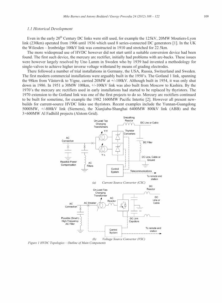
(a) Current Source Converter (CSC)
(b) Voltage Source Converter (VSC) Figure 1 HVDC Topologies – Outline of Main Components

110 Mike Barnes and Antony Beddard / Energy Procedia 24 ( 2012 ) 108 – 122
Since AC has to be converted to DC, some impedance is required between the two inputs to match power flows, store energy and be used by the power electronic devices to convert a DC to three (or more) AC flows. Thyristor and mercury arc schemes are ‘current source’ stations. An inductance on the DC side acts as the energy storage element. In effect the DC current is held constant and commutated from AC phase to AC phase. Thyristors or mercury arc rectifiers control the point at which one AC phase could start to take over conduction from another. However the actual commutation of current from one phase to another is undertaken by the AC voltages. Such systems are hence called ‘Current Source Converters’ (CSC) or ‘Line-Commutated Converters’ (LCC). Such stations require a strong AC network to undertake commutation, draw large amounts of reactive power and generate a large number of low-order harmonics due to the ‘blocky’ shape of current resulting from the low-frequency commutation process. The station footprint is therefore fairly large due to the harmonic filters and reactive power compensation required, Figure 1(a).
Since the 1990’s another technology has been available. This uses a capacitor as the interface impedance and energy storage element and appears as a constant voltage on the DC side. It uses self-commutating IGBTs. Such systems are referred to as ‘Voltage Source Converters’ (VSC) or ‘Self-Commutated Converters’ (SCC). Because the devices are self-commutating they do not need a strong AC grid and can switch at high frequency (kHz), eliminating low order harmonics and controlling the phase shift between output voltage and current on the AC side. This may eliminate the need for AC filters, DC filters, reactive power compensation and greatly reduces station footprint, Figure 1(b). Due to the frequent switching and use of IGBTs rather than thyristors, the losses of VSC systems is slightly greater than for CSC. Thus VSC is used where black-start capability is required or space constraints mean CSC is not cost effective – examples include offshore platforms and dense urban environments. CSC is still used for very large power transfers where efficiency is paramount.
1.2 VSC HVDC Development
Figure 2 - First generation converter – each diagram of an IGBT and diode represents a ‘valve group’ – i.e. a string of series/parallel devices.
Voltage source converters have gone through a distinct series of generations. First generation converters used technology broadly similar to industrial drives (though at much higher voltage) and were two-level six-switch converters with pulse-width modulation, Figure 2. This produced a two-level output. The output AC voltages Vabc were synthesized by alternating between +½Vdc and -½Vdc. This required a fairly high Pulse-Width Modulation (PWM) frequency and consequently significant switching losses. In contrast to industrial drives, each ‘valve group’, figure 2, was not a single switch but a series string of switches and diodes controlled to switch in synchronism. In HVDC-Light, ABB use feedback of the
Mike Barnes and Antony Beddard / Energy Procedia 24 ( 2012 ) 108 – 122 111
voltage across each IGBT to modulate (or boost) the gate drive and thus control the voltage sharing between devices [3].
In the second generation, ABB switched to a derivative of the neutral-point clamped converter, Figure 3. Advanced NPC converters place an additional IGBT in anti-parallel with the two central capacitor diodes. Here the output can be synthesized from +½Vdc, 0V and -½Vdc. This allows the switching frequency to appear higher with the same number of switching transitions per switch. This allows a reduction in device switching losses without making harmonic content or current ripple worse.
ABB’s installations subsequently returned to two-level systems using ABB’s ‘Optimum PWM’. Combining elements of programmed selective harmonic-elimination PWM and third harmonic injection, this combination of techniques apparently significantly reduces system losses.
Table 1 – Evolution of VSC-HVDC technology
Technology Year first scheme
commissioned Converter Type Typical Losses per
converter (%)aSwitching
frequency (Hz)b Example Project
HVDC Light 1st Gen 1997 Two-Level 3 1950 Gotland
HVDC Light 2nd Gen 2000 Three-level Diode NPC 2.2 1500 Eagle Pass
2002 Three-level Active NPC 1.8 1350 Murraylink
HVDC Light 3rd Gen 2006 Two-Level with OPWM 1.4 1150 Estlink
HVDC Plus 2010 MMC 1 <150* Trans Bay Cable
HVDC MaxSine 2014 MMC 1 <150* SuperStation
HVDC Light 4th Gen 2015 CTL 1 =>150* Dolwin 2c
*switching frequency is for a single module/cell.
Siemens have changed the converter design further, using the so-called Modular-Multilevel Converter (MMC) design proposed by Marquardt, Figure 4. Since each sub-module may switch in and out only once per cycle, the effective switching frequency of each switch device can be reduced to the fundamental frequency. Since many levels are used (typically 200+) the resulting output waveform appears to be virtually sinusoidal, eliminating the need for DC and AC filters. Switching losses are therefore substantially reduced in MMC systems compared with PWM systems [10]. Both Alstom Grid and ABB are producing products similar to the MMC topology. A variety of other topologies have been produced with a good summary given in [11].
A summary of the evolution of the converter is given in table 1. The cascaded-two level converter (CTL, ABB) uses a series connection of power electronic devices in each sub-module thus reducing the number of sub-modules but increasing the voltage on each DC capacitance.
a Losses are indicative of a particular converter type, not specific to a project. The HVDC Light losses are primarily estimated from a graph produced by ABB, which can be found in [4]. The figure for HVDC Plus losses is in [5]. HVDC MaxSine losses are based on the HVDC Plus losses since the converter designs are very similar. b Switching frequency for HVDC light generations 1-3 are for the example projects and can be found in [6, 7]. Switching frequencyfor HVDC plus is based on [8]. The same value is also used for MaxSine. c Dolwin 2 is likely to be the first HVDC Light 4th generation project based on correspondence with ABB and in [9] its states losses less than 1%, which implies 4th generation technology will be used.

112 Mike Barnes and Antony Beddard / Energy Procedia 24 ( 2012 ) 108 – 122
Figure 3 - One phase of a second generation neutral-point clamped (NPC) converter – each IGBT and diode represents a string of series/parallel devices.
Figure 4 – Single Phase of the Modular-Multi-Level Converter (MMC) or Marquardt converter used by Siemens and Alstom Grid

Mike Barnes and Antony Beddard / Energy Procedia 24 ( 2012 ) 108 – 122 113
Since semiconductor switch design is a trade-off between fast switching, lower conduction losses or higher blocking voltaged there are further advantages to a lower switching frequency. This in turn potentially allows more emphasis to be put on conduction loss minimisation and increasing switch blocking voltage in the semiconductor switch design and selection, an additional benefit over and beyond the switching frequency reduction.
At present efficiencies range from 1% to 3% for a VSC-HVDC system (for one converter) compared with 0.8% of a conventional thyristor line commutated system, table 1.
1.3 Control
Control occurs at several levels, often the same levels at which protection functions are grouped. This discussion assumes a Modular-Multi-level Converter (MMC). Moving from the lowest to the higher level, a typical hierarchy would be:
Sub-module level control – This describes the control of the IGBT switching within each sub-module of Figure 4. It includes local over-voltage and over-current protection, for example the local triggering of the protection thyristor or mechanical by-pass switch. In also encompasses the exchange of information between the sub-module and higher level controllers.
Phase leg control – Within each phase leg, the output of the required voltage at the AC terminal must be coordinated. Given the number of levels available, there are a multitude of possible switching states which can deliver a given output. The phase leg control must not only produce the required AC voltage, it must also ensure voltage balancing of the DC voltage levels on the capacitors of each sub-module is achieved by switching in (or out) appropriate sub-modules. This complicates phase-leg control compared with ordinary two-level systems since two control loops are required: one to synthesise the AC voltage one to balance DC sub-modules [30]. Careful controller design is required to avoid conflict. In essence two strategies exist. In the first each DC voltage level is switched in and out once per cycle, in the second some degree of repeated switching between adjacent voltage states (PWM) is allowed.
Converter control – At this level the output of the converter is controlled to produce a given power flow, current flow or control of the DC voltage. So-called ‘direct control’ regulates the AC voltage and phase to control power. ‘Vector control’ regulates output current in the dq domain to in turn control power flows [12]. It is worth noting that vector control is more widely used in industrial drives, since the power loop bandwidth using dq current control can be made faster than using voltage control alone.
Station control – In addition to using the converter to manage power flows and voltage, the functions of each converter must be coordinated with other equipment that may perform similar functions. For example the converter must be coordinated with control from any on-load tap changers and all protection within a station needs careful holistic design. So far most installations have been monopoles, usually balanced monopoles, i.e. a single converter feeding balanced positive and negative DC lines. However if a bipolar system is installed both converters in a station need coordination.
System network control coordination – This ensures that AC and DC system-wide control functions are performed. On the DC side all converters feeding into a system need to have their control coordinated (see below). On the AC side the HVDC station needs to be coordinated with other AC units. This includes voltage set-points, but also power oscillation damping control, sub-synchronous torsional interaction, start-up and shutdown.
Current practice uses duplicate protection and control systems [13, 14].
To coordinate multiple stations on the DC side, two main control methods have been suggested.
d High blocking voltage allows fewer switches or sub-modules per valve-group or higher voltages with the same number of sub-modules.

114 Mike Barnes and Antony Beddard / Energy Procedia 24 ( 2012 ) 108 – 122
In quasi-independent converter control [15, 16] pre-programmed control characteristics (usually droop lines) are used for each converter. A system such as shown in figure 5 results. The inverter has a control characteristic based on local voltage and DC current or power. The operating point on the characteristic depends on the intersection of the inverter and rectifier characteristics. Assuming negligible DC line voltage drops, for a point-to-point system consisting of the inverter and rectifier R1, the operating point is the intersection between the two line characteristics. If the central zone is flat, as for the inverter, then it becomes the ‘slack DC bus’ controlling the DC network voltage and absorbing/injecting power to maintain this voltage. More converters can be added, for example rectifier R2. The operating point then becomes the intersection of the composite inverter and rectifier characteristics (again assuming negligible voltage drops along the DC line). Some degree of sharing between converters can be achieved by adding voltage droop with current (as for the central R1, R2 zone).
Figure 5 – Example VSC-HVDC Droop Line Control
Master-slave control is an alternative discussed by a number of authors. Here some form of communication is undertaken between converter stations. The ‘master control’ (usually based at one station) controls the subordinate stations. Some fail-safe methodology for local station control is still required in case of telecommunications failure. Such control might be used to supplement quasi-independent control and optimise local set-points according to the state of the remaining network. A good summary of issues surrounding this problem are discussed in [17] for LCC-HVDC. A good summary of protection issues is also provided in [15, 16].
2. Key Issues
Voltage Source HVDC is a new and rapidly developing field. The rating of installations has increased rapidly from several hundred MW to planned installations of 1000MW and more only over the last few years. Nevertheless there are some key concepts which are particularly deserving of attention, especially for some of the offshore multi-terminal networks presently being considered.

Mike Barnes and Antony Beddard / Energy Procedia 24 ( 2012 ) 108 – 122 115
2.1 DC Circuit Breakers
Present VSC-HVDC systems are two-terminal point-to-point installations and clear faults by using AC side breakers, and as such do not need DC breakers e.g. [14]. For multi-terminal systems, such as shown in Figure 6, a fault would mean that AC breakers trip, the whole DC network is de-energised, fast isolation switches isolate the fault, the DC system is re-energised and operation continues. This would take a considerable time and does not fit in well with conventional protection philosophy.
Accordingly, there has been substantial investigation into DC circuit breakers. The challenge here is that there is no current and/or voltage zero as would be found in AC breakers. Thus breaking the current flow is substantially more challenging. A number of solutions have been presented.
Figure 6 Multi-terminal DC Network with offshore cable fault
The passive DC circuit breaker consists of an interrupter, BRK, in parallel with two branches; one containing a series inductor, L, and capacitor, C, the other a surge arrestor, as shown in Figure 7(a). This is the type used in metallic return transfer breakers in conventional LCC-HVDC [18]. It would most likely not be sufficiently fast for use in VSC-HVDC.
Alternatives exist however. The hybrid circuit breaker [19] uses a mechanical switch in the main path, S, to normally conduct current, figure 7(b). In response to a trip command, the semiconductors conduct, diverting current. The main switch, S, is opened and once it has recovered its blocking capability the semiconductor switches are turned off. Figure 7(c) is similar but the divert path now helps limit the rate of rise across the main path [19]. All-solid-state solutions exist, Figure 7(d), in which the main path comprises a series of semiconductor switches. These can switch off rapidly and a voltage limiting device can limit the breaking energy dissipated in the switches. However the number of devices from which the main breaker is manufactured required is large (due the fault current magnitude and also the peak voltage rating of the breaker) and this increases cost and on-state losses.

116 Mike Barnes and Antony Beddard / Energy Procedia 24 ( 2012 ) 108 – 122
A novel solution has been suggested by ABB [20], Figure 7(e). The main circuit breaker is a solid state device but is placed in parallel to the normal conduction path. A mechanical switch in the main path has a semiconductor switch in series with it to aid commutation to the main breaker path. This auxiliary switch need only have a low blocking voltage and therefore may consists of few semiconductor devices with low on state losses. Other DC breakers are being developed but no commercial installations of VSC-HVDC systems with DC breakers appear to have been made at the time of writing.
(a) Passive Resonance Circuit Breaker (b) Hybrid Circuit Breaker
(b) Mechanical Breaker with Turn-Off Snubber (d) Solid State Circuit Breaker
(e) ABB Circuit Breaker
Figure 7 – Passive Resonance Circuit breaker
2.2 Multi-terminal Control
Multi-terminal control is a significant remaining issue. Principles have been discussed by a number of authors [15, 16, 21-27] but no consensus view has been formulated. Multiple concepts have been discussed but no standards appear to have yet emerged. A good qualitative review of the key issues is given in [23 and 24]. Initial studies are starting to develop the concepts using simulation and analysis [25], or simulation and low-power hardware models [26] but models are still relatively straightforward
Mike Barnes and Antony Beddard / Energy Procedia 24 ( 2012 ) 108 – 122 117
and tend to have few DC terminals. Important factors like the impact of the characteristics of the wind-farms in such systems have however been highlighted [27].
The twin issues of converter interoperability and protection coordination remain key. It is to be expected that in future if large on- or offshore grids develop, then different manufacturers will be connecting their converters to the same DC network. Such systems will have to operate with compatible voltage levels, compatible local control and compatible telecommunications. Such compatibility needs to be guaranteed even over future software and hardware upgrades. If DC networks connect two unsynchronised AC grids then the impact of connecting these, each with potentially its own variations in operation philosophy, needs to be considered. Protection methodologies and philosophies will also need to be compatible and coordinated.
Some long-distance multi-terminal VSC-HVDC pilot projects are being discussed and it is expected that multi-terminal control and protection issues will be clearer once practical experience is gained. As yet experience with practical multi-terminal systems is limited. The Shin-Shinano substation in Tokyo has been constructed by Toshiba, Hitachi and Mitsubishi Electric [28]. This back-to-back multi-terminal VSC-HVDC station uses GTOs. Its relatively low power (53MVA per converter) and the location of the three-terminals at one site, and the easier control schemes resulting, do limit the degree to which experience with this installation can be extended to offshore multi-terminal DC systems. However so far this is the only large-scale multi-terminal VSC-HVDC installation. Both the Hydro-Quebec [29] installation and the SACOI scheme [29] in Italy use LCC. In both cases it could be argued that the system is not really truly multi-terminal, since power flow is either unidirectional (Hydro-Quebec) or one terminal is in effect a small tap on a larger HVDC scheme (SACOI). Plans for multi-terminal systems are developing however. Examples at various stages of development include Tres-Amigas [33], the Scotland-Shetland Offshore hub [34], the Atlantic Offshore Wind Connection [35] and the North Sea in Europe [36].
2.2 Reliability
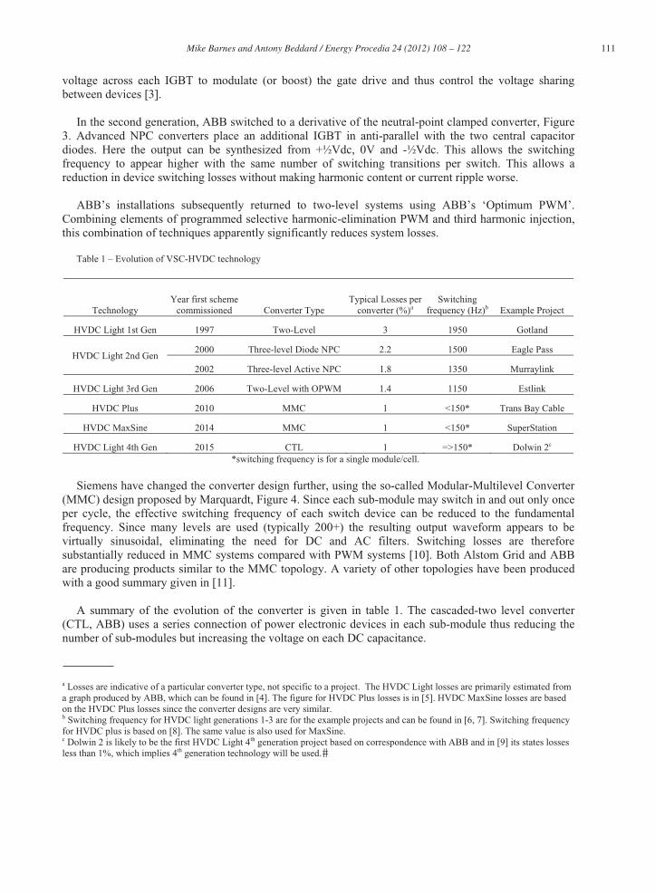
The availability of any transmission scheme is a significant factor in determining if the scheme is technically and commercially viable. The UK alone is expected to build more than twenty-five 1GW VSC-HVDC links for the connection of offshore windfarms. Therefore accurately predicting the availability of these links is of paramount importance.
Figure 8 – 1GW VSC-HVDC Link for the Connection of an Offshore Windfarm
Reliability data from VSC-HVDC schemes is instrumental in estimating the availability of future VSC-HVDC schemes with multi-modular converters. Furthermore the analysis of the availability data will allow the key components which affect the scheme’s availability to be identified and mitigation strategies to be developed. To date the owners and operators of the 12 commissioned VSC-HVDC schemes have however chosen not to submit data to the Cigre B4.04 Advisory group, which biannually

118 Mike Barnes and Antony Beddard / Energy Procedia 24 ( 2012 ) 108 – 122
publishes the results of a world HVDC reliability survey. Some reliability data for the Murraylink and Cross Sound Cable project has however been published in Cigre paper [37].
Cigre surveys as well as industrial and academic papers were used to carry out an availability analysis in the absence of any detailed VSC-HVDC reliability data. The link analysed is for the connection of an offshore windfarm and is shown in Figure 8. Summary results are shown in Figure 9.
54%
10%
9%
8%
9%10%
Component Importance for AvailabilityDCCable Offshore MMC
Offshore Reactor Offshore DC Switchyard
Other Offshore Equipment Onshore Equipment
Figure 9 – Component Importance for Availability
Preliminary results show that the scheme has an overall availability of 96.5% excluding downtime for scheduled maintenance. One MWh of energy generated by an offshore windfarm in the UK is worth
approximately £150e(€174.5)f. Based on a capacity factor of 0.4, the VSC-HVDC link’s unavailability
costs approximately £18.4m (€21.4m) per year in lost revenue. The 165km submarine cable was found to have the greatest impact on the scheme’s availability and was consequently responsible for approximately 54% of the schemes downtime. Every effort must therefore be made to ensure that failures of submarine cables are minimised.
The results from any availability analysis, no matter how comprehensive the methodology, are only ever as good as the input data. New surveys for components in VSC-HVDC schemes are required to give availability analysis results greater credibility.
e This figure is based on one MWh of energy generated by an offshore windfarm being equal to the electricity wholesale price plustwo renewable obligations certificates (ROC) plus one levy exemption certificate (LEC). The electricity wholesale price is approximately £60/MWh [38]. Accredited offshore windfarms are currently awarded 2 ROC’s per MWh [39], where each ROC is worth £38.69 plus 10% [40]. One LEC has a value of £4.85 [41]. f Based on the exchange rate at the time of writing, which is £1=€1.163.

Mike Barnes and Antony Beddard / Energy Procedia 24 ( 2012 ) 108 – 122 119
0.0252 [m]
Cable # 1
0.0402 [m].043 [m].048 [m].053 [m].057 [m]
1.5 [m]
0 [m]
ConductorInsulator 1
SheathInsulator 2
ArmourInsulator 3
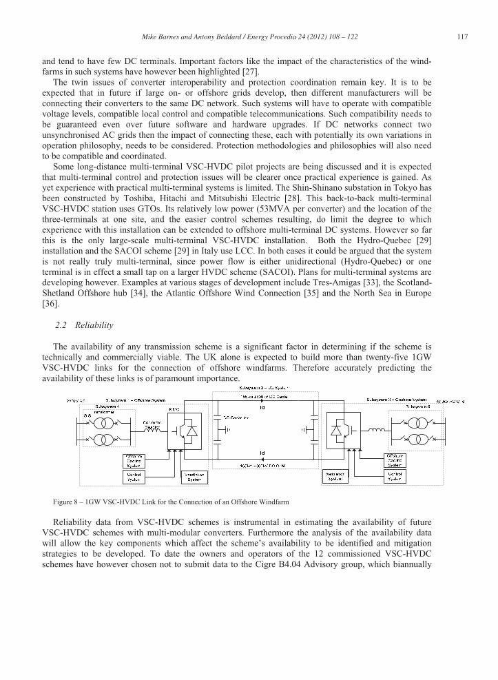
2.3 Cable Modelling
A VSC-HVDC cable has a complex structure consisting of multiple layers, Figure 10. There are several commercially available cable models which could be used to represent the behaviour of this type of cable. The main cable models which are available in PSCAD and SimPower Systems are briefly discussed below:
PI-section model. This model lumps the cable’s resistance, R, capacitance, C, and inductance, L, together and is generally adequate for steady-state simulations and for modelling short lengths of cable. As the frequency of interest or the length of cable increases, more PI-sections are required to account for the distributed nature of the cable. This leads to additional computation time. This type of model is readily available in both PSCAD and SimPower Systems.
Bergeron model - The Bergeron model is based on travelling wave theory and represents the distributed nature of the cables LC parameters. The cable’s resistance is lumped together and divided into three parts, 50% in the middle of the cable and 25% at each end. This model, similar to the PI-section does not account for the frequency dependence of the cable’s parameters and is therefore essentially a single frequency model. Both PSCAD and SimPower Systems contain a form of the Bergeron model.
Frequency-dependent Models - Frequency dependent models represent the cable as a distributed RLC model, which includes the frequency dependency of all parameters. This type of model requires the cable’s geometry and material properties to be known. There are two frequency dependent models available in PSCAD; the frequency dependent mode model and the frequency dependent phase model. The difference between the two models is that the phase model represents the frequency dependency of the internal transformation matrix, whereas the mode model assumes the matrix to be constant. The frequency dependent phase model is said to be the most robust and numerically accurate line/cable model commercially available anywhere in the world [42].
It is unclear at this time which of these models is most suitable for VSC-HVDC control and protection studies. Further work should be undertaken to investigate this. The recommendations from these studies would be helpful in developing a standard HVDC cable model as part of an overall VSC-HVDC benchmark model.
3. Summary
This paper has given a brief overview of the position of voltage-source converter HVDC technology at the present time. Key issues of multi-terminal control, protection, reliability and cable modelling and design have been identified and commented upon. This is a rapidly developing area and much is likely to change over the coming years however.
Figure 10 – Cable Construction in PSCAD

120 Mike Barnes and Antony Beddard / Energy Procedia 24 ( 2012 ) 108 – 122
Table 2 - VSC-HVDC Projects to Date
Project Location Manufacturer Commissioned Type Power /MW DC voltage /kV length/km
Hällsjön Sweden ABB 1997 OHL 3 10 10
Gotland Sweden ABB 1999 Cable 50 80 70
Shin-Shinano Japan Toshiba, Hitachi,Mitsubishi
1999 BTB R&D
53x3 10.6 BTB
Terranora(Directlink)
Australia ABB 2000 Cable 180 80 3x59
Tjaereborg Denmark ABB 2000 Cable 7.2 9 4x4.3
Eagle Pass USA ABB 2000 BTB 36 15.9 BTB
Cross Sound, USA USA ABB 2002 Cable 330 150 40
Murraylink Australia ABB 2002 Cable 220 150 180
Troll 1&2 Norway ABB 2005 Cable 2x44 60 2x70
Estlink Finland-Estonia
ABB 2006 Cable 350 150 105
Caprivi Link, Namibia
Namibia ABB 2009 OHL 300 -350 mono 970
Trans Bay Cable USA Siemens 2010 Cable 400 200 85
NordE.ON1 / BorWin1
Germany ABB 2012 Cable 400 150 200
Valhall Norway ABB 2011 Cable 78 150 292
East-West Link Ireland-UK ABB 2012 IP Cable 500 200 261
Dolwin1 Germany ABB 2013 IP Cable 800 320 165
BorWin2 Germany Siemens 2013 IP Cable 800 300 200
Helwin1 Germany Siemens 2013 IP Cable 576 250 130
NordBalt Sweden-Lithuania
ABB 2013 IP Cable 700 300 450
Inelfe France-Spain Siemens 2013IP Cable 2x1000 320 60
Skagerrak 4 Denmark-Norway
ABB 2014IP Cable 700 5001 244
SylWin1 Germany Siemens 2014IP Cable 864 320 210
Tres Amigas USA Alstom Grid 2014IP BTB 7502 345 n/a
DolWin2 Germany ABB 2015IP Cable 900 320 135
NordBalt Sweden-Lithuania
ABB 2015IP Cable 700 300 450
Troll 3&4 Norway ABB 2015IP Cable 2x50 60 2x70
HelWin2 Germany Siemens 2015IP Cable 690 320 131
IP= in progress, OHL=overhead line, BTB=Back-to-Back 1 – Skagerrak 4 is a monopole but in a bipolar configuration with an LCC-HVDC line. 2 – Converter module size. Sources: [31-33]
Acknowledgements
The authors would like to acknowledge the support of EPSRC Supergen Wind Energy Technologies Consortium supporting this work.
Mike Barnes and Antony Beddard / Energy Procedia 24 ( 2012 ) 108 – 122 121
References
[1] J Arrillaga, “High Voltage Direct Current Transmission”, 2nd edition, IET 1998. [2] Working Group on HVDC and FACTS Bibliography and Records, IEEE DC and Flexible AC Transmission Subcommittee “HVDC Projects Listing”, July 2009, http://www.ece.uidaho.edu/hvdcfacts/Projects/HVDCProjectsListingJuly2009-existing.pdf [3] LL, Livermore, Jun Liang, and J Ekanayake, “MTDC VSC Technology and its applications for Wind Power”, Universities Power Engineering Conference (UPEC), 2010. [4] P Jones, Presentation slides, “HVDC –Enabling the Transition to an Energy System based on Renewables", IET ACDC Conference, 2010. [5] Siemens, "HVDC PLUS – Basics and Principle of Operation", Siemens, 2008. [6] JL Arrillaga, “Flexible Power Transmission - The HVDC Options”, Wiley, 2007 [7] L Ronström, ML Hoffstein, R Pajo, and M Lahtinen, "The Estlink HVDC Light® Transmission System," CIGRÉ Regional Meeting, 2008. [8] Siemens, "MMC", http://www.energy.siemens.com/mx/en/power-transmission/hvdc/hvdc-plus/modular-multilevel-converter.htm#content=Details [accessed: August 2011] [9] ABB,“Dolwin2", http://www.abb.co.uk/industries/ap/db0003db004333/e1e1631ca0d 32a92c12578 db0034cdbf.aspx [accessed: August 2011] [10] Yushu Zhang, GP Adam, TC Lim, SJ Finney and BW Williams, “Voltage Source Converter in High Voltage Applications: Multilevel versus Two-level Converters”, IET AC/DC Conference, 2010[11] C Davidson and DR Trainer,“Innovative Concepts for Hybrid Multi-Level Converters for HVDC Power Transmission”, IET AC/DC Conference, 2010[12] Cigre. Working Group B4.37: VSC Transmission, Report 269. Cigre, 2005 [13] MD Davies, ”HVDC PLUS – Basics and Principle of Operation”, Siemens company technical report, 2008 [14] ABB, “It's Time to Connect”, ABB company technical report, 2010[15] R Forest, G Heyner, KW Kanngeisser, and H Waldmann, "Multiterminal Operation of HVDC Converter Stations", IEEE Trans. Power Appartus and Systems, vol. 88, no. 7, 1969, pages 1042-1052. [16] L Xu, L Yao, and M Bazargan, "DC Grid Management of a Multi-terminal HVDC Transmission System for Large Offshore Wind Farms", International Conference on Sustainable Power Generation and Supply. 2009.[17] J Reeve, IA Rose, and J Carr, “Central Computer Controller for Multiterminal HVDC transmission systems”, IEEE Trans. Power Apparatus &Systems, vol. 96, no. 3, 1977, pages 934-944. [18] Alstom Grid, “HVDC – Connecting the Future”, Alstom Grid publishers, 2010 [19] C Meyer, M Kowal, and RD Doncker, "Circuit Breaker Concepts for Future High-Power DC-Applications", IEEE Industry Applications Conference, vol. 2, 2005, pages 860-866. [20] J Häfner and B Jacobsen, “Device and Method to Break the Current of a Power Transmission or Distribution Line and Current Limiting Arrangement”, Patent PCT/EP2009/065233, Filed 16th Nov 2009. [21] C Du, A Agneholm and G Olsson, “Comparison of Different Frequency Controllers for a VSC-HVDC Supplied System”, IEEE Trans. Power Delivery, vol. 23, no. 4, 2008, pages 2224-2232. [22] F Nozari, CE Grund, and RL Haut, "Current Order Coordination in Multiterminal DC Systems", IEEE Trans. Power Appartus and Systems, vol. 100, no. 11, 1981, pages 4628-4635. [23] N Ahmed, A Haider, D Van Hertem, Lidong Zhang and HP Nee, “Prospects and Challenges of Future HVDC SupergGrids with Modular Multilevel Converters”, European Power Electronics and Applications Conference (EPE), 2011. [24] RS Whitehouse, “Technical Challenges of Realising Multi-terminal Networking with VSC”, European Power Electronics and Applications Conference (EPE), 2011. [25] L Xu, and L Yao, “DC Voltage Control and Power Dispatch of a Multiterminal HVDC System for Integrating Large Offshore Windfarms”, IET Renewable Power Generation, vol. 5, issue 3, 2011, pages 223-233 [26] Jun Liang, Tianjun Jing, O Gomis-Bellmunt, J Ekanayake and N Jenkins, “Operation and Control of Multiterminal HVDC Transmission for Offshore Windfarms”, IEEE Trans. Power Delivery, vol. 26, issue 4, 2011, pages 2596-2604. [27] O Gomis-Bellmunt, A Egea-Alvarez, A Junyent-Ferre, Jun Liang, J Ekanayake and N Jenkins, “Multiterminal HVDC-VSC for Offshore Wind Power Integration”, IEEE Power and Energy Society General Meeting, 2011 [28] Nakajima, Tatsuhito, and Shoichi Irokawa, "A Control System for HVDC Transmission by Voltage Sourced Converters", IEEE Power Engineering Society Summer Meeting, 1999. [29] WF Long, J Reeve, JR McNichol, MS Holland, JP Taisne, J LeMay, and DJ Lorden, "Application Aspects of Multiterminal DC Power Transmission", IEEE Trans. Power Delivery, vol. 5, no. 4, 1990, pages 2084-2098. [30] C Oates and C Davidson, “A comparison of two methods of estimating losses in the Modular Multilevel Converter”, European Power Electronics and Applications Conference (EPE), 2011. [31] ABB Company Website, “HVDC Light”, http://www.abb.com/industries/us/9AAC30300394.aspx, [Accessed: 19th November 2011.] [32] Siemens Company Website, “HVDC Plus Technology”, http://www.energy.siemens.com/hq/en/power-transmission/hvdc/hvdc-plus/, [Accessed: 19th November 2011] [33] Global Transmission Report Website, “Alstom to supply HVDC technology for Tres Amigas”, 25th April 2011, http://www.globaltransmission.info/archive.php?id=7922, [Accessed: 19th November 2011]
122 Mike Barnes and Antony Beddard / Energy Procedia 24 ( 2012 ) 108 – 122
[34] European Commission Energy Website, “Offshore Wind Energy”, http://ec.europa.eu/energy/eepr/owe/owe_en.htm, [Accessed: 23rd November 2011] [35] Atlantic Wind Connection website, “AWC Intro”, http://atlanticwindconnection.com/uncategorized/aws-intro/, [Accessed: 23rd
November 2011] [36] TK Vrana and OB Fosso, “Technical Aspects of the North Sea Super Grid”, Cigré Electra, number 258, October 2011, pages 6-19. [37] S. Dodds, B. Railing, K. Akman, B. Jacobson, T. Worzyk, and B. Nilsson, "HVDC VSC (HVDC light) transmission – operating experiences," Cigre 2010, 2010. [38] Ofgem, "Electricity and Gas Supply Market Report," Oct 2011. [39] Department of Energy and Climate Change, "Eligible renewable sources and banding levels", http://www.decc.gov.uk/en/content/cms/meeting_energy/renewable_ener/renew_obs/eligibility/eligibility.aspx [accessed: Novemeber 2011] [40] Ofgem, "The Renewables Obligation Buy-Out price and Mutualisation Ceiling 2011-2012," 2011. [41] Ofgem, "Climate Change Levy: Renewables Exemption", http://www.ofgem.gov.uk/Sustainability/Environment/cclrenexem/Pages/CCLRenewablesExemption.aspx [accessed: November 2011] [42] PSCAD on-line help, "Frequency Dependent Line Models."


![Distributed PLL-based Control of Offshore Wind Turbines ...€¦ · distance offshore wind power transmission [1]-[7]. To date, voltage-source-converter based HVDC (VSC-HVDC) links](https://img.dokumen.tips/doc/110x75/5ea2b21262bde80d0215fab0/distributed-pll-based-control-of-offshore-wind-turbines-distance-offshore-wind.jpg)