Embed Size (px)
Citation preview
VoIP Security Best Practice Vol. IIIConfiguration Guide for Secure VoIP Systems
VoIP Security Best Practice
Vol. III
Configuration Guide for Secure VoIP Systems
(Version: 1.3)
NEC Corporation
VoIP Security Best Practice Vol. IIIConfiguration Guide for Secure VoIP Systems
i
Contents
1. Introduction...................................................................... 11.1 Abstract ..............................................................................................1
1.2 Audience.............................................................................................1
1.3 Author .................................................................................................2
1.4 Acknowledgements............................................................................2
2. Guideline and Configuration for VoIP InfrastructureDevices............................................................................. 3
2.1 UNIVERGE SV7000.............................................................................3
2.1.1 Terminal authentication ................................................................ 3
2.1.1.1 Terminal authentication mechanism ...................................... 32.1.1.2 Configuration ......................................................................... 4
2.1.2 Encryption and terminal authentication......................................... 5
2.1.2.1 The encryption key agreement mechanisms.......................... 62.1.2.2 SIP complete encryption and partial encryption ..................... 92.1.2.3 Encryption configuration .......................................................11
2.2 IP Phone Terminal ............................................................................13
2.2.1 DtermIP (SIP) ..............................................................................13
2.2.1.1 Terminal Authentication Configuration ..................................132.2.1.2 Encryption Configuration ......................................................132.2.1.3 Registrar Destination configuration .......................................14
2.2.2 UTerm (NETerm60).....................................................................15
2.2.2.1 Terminal authentication configuration ...................................152.2.2.2 Encryption configuration .......................................................152.2.2.3 Registrar Destination configuration .......................................16
2.2.3 DtermSP30..................................................................................16
2.2.3.1 Terminal Authentication Configuration ..................................162.2.3.2 Encryption Configuration ......................................................17
2.3 The Other Equipments.....................................................................19
2.3.1 MG(BRI)-SIP ...............................................................................19
2.3.1.1 Encryption configuration .......................................................19
3. Guideline and Configuration for Firewall and IPNetwork Infrastructure .................................................. 20
3.1 Firewall..............................................................................................20
3.1.1 Juniper NetScreen firewall...........................................................21
3.1.2 Checkpoint Firewall-1 ..................................................................21
3.2 IP Network Infrastructure Device ....................................................22

VoIP Security Best Practice Vol. IIIConfiguration Guide for Secure VoIP Systems
ii
3.2.1 Layer 2 Switch Configuration (VLAN-based Logical Separation) .22
3.2.1.1 Cisco Catalyst Switch Series ................................................233.2.1.2 UNIVERGE QX Switch Series ..............................................253.2.1.3 UNIVERGE CX Switch Series ..............................................263.2.1.4 BF210/24 Switch ..................................................................26
3.2.2 Layer 2 switch (802.1X authentication) ........................................27
3.2.3 Router or Layer 3 Switch (RFC2827-based ingress filtering) .......28
4. Guideline and Configuration for User AccessInfrastructure ................................................................. 29
4.1 Remote Access from the Internet ...................................................29
4.1.1 IPsec-based Remote Access.......................................................29
4.1.2 SSL-based remote access...........................................................29
4.2 Wireless LAN Controller ..................................................................30

VoIP Security Best Practice Vol. IIIConfiguration Guide for Secure VoIP Systems
1
1. Introduction
1.1 Abstract
Network security is one of the top concerns for every organization these days.An increasing number of regulations have been issued in most regions. Securitybreaches might cause damage to an organization’s reputation and/or loss ofbusiness opportunities if occurred. Although IP telephony solutions allow for anew way of office communication while reducing network costs, it does howeveradd complexity onto the development and maintenance of corporate networksbecause of the unique natures of such systems and the coexistence of data andvoice traffic. The purpose of this “UNIVERGE VoIP Security Best Practice”series is to provide the basic guidelines for deploying and maintaining highlysecure UNIVERGE IP telephony systems.
This document is the third volume of a series of Security Best Practice fordesigning and implementing secure IP telephony systems. Its primary goal isproviding device configuration information in accordance with the principlesprovided in the first volume and the security models provided in the secondvolume.
1.2 Audience
UNIVERGE VoIP Security Best Practice is intended for network and systemmanagers. Although this document is essentially technical, it can be readwithout understanding network and system details. Unlike other volumes, thisvolume contains some of configuration examples of the UNIVERGE SV7000 andnetwork equipments. In order to understand this volume completely, the extraknowledge about these equipments will be needed.
The security practice is composed of many volumes to provide proper informationas it relates to your specific needs or purposes. Use the first and second volumein order to better understand the security overview. While you can use volumestwo and three if your interest is focused on integrating secure VoIP systems.
Since comprehensive security for a corporate network includes too many aspectsto cover, in this series, we focus on basic issues that are specific to IP telephonysystems. For example, we presume that your organization already has asecurity policy. NEC does not recommend deploying any security technologiesor devices without first establishing a security policy.
VoIP Security Best Practice Vol. IIIConfiguration Guide for Secure VoIP Systems
2
1.3 Author
Teruharu Serada is the primary author of this white paper.
Mr. Serada works within UNIVERGE® product and solution planning as a networksecurity technology expert within the UNIVERGE® Solutions Promotion Division.
1.4 Acknowledgements
Special thanks to Mr. Sam Safa and Mr. Richard Sitters for their technical andgrammatical refinement of our manuscript.

VoIP Security Best Practice Vol. IIIConfiguration Guide for Secure VoIP Systems
3
2. Guideline and Configuration for VoIPInfrastructure Devices
The security mechanisms and configuration example of each device in VoIPinfrastructure (described at second volume) is described in this section.
2.1 UNIVERGE SV7000
NEC’s SV7000 (IP-PBX) has the two following security-related functions:
Terminal Authentication Mitigate from malicious users attacks
Communication encryption Provide Communication Confidentiality
2.1.1 Terminal authentication
2.1.1.1 Terminal authentication mechanism
It is possible for IP-PBX to mitigate the possibility of the attacks, by authenticatingthe terminal. The terminal is authenticated by SV7000 and the telephonenumber is used as identifier. The authentication mechanism is so-calledchallenge-response authentication and based on HTTP digest authenticationdefined by RFC2617. This authentication is NOT mutual, i.e. only the terminal isauthenticated, and the SV7000 is not. This actually implies that the terminal is not100% sure of the identity of the voice server. When mutual authentication isneeded between SV7000 and the terminal, the one-time password authentication(described at section 2.1.2) should be used.
The goal of the HTTP digest mechanism is the authentication of the SIP terminalduring a call setup. This authentication is based on a simple challenge-responsemechanism where the SIP server (in this case the SV7000) challenges theterminal to give the right answer to a question. If the answer is correct the terminalis authenticated. The terminal is challenged by the SIP server (SV7000) sending aso called nonce. The response to this nonce should contain a hash (MD5checksum) of the terminal’s username, password and the given nonce value itself(to prevent the replay attack). Since the MD5 checksum is returned to the SV7000(not the actual username and password), the message cannot be intercepted byan attacker to reveal the real username and password of the terminal. As a result,the message cannot be intercepted for a replay attack as the hash is also over thenonce value itself. Figure 2-1 shows the authentication flow process.

VoIP Security Best Practice Vol. IIIConfiguration Guide for Secure VoIP Systems
4
Figure 2-1 Terminal Authentication Flow
2.1.1.2 Configuration
The default password, used in the terminal authentication, is same as the STNnumber, configured by AISTL command on the SV7000. When a passwordchange is needed, an ASPW command is used to. The LSPW command can alsobe used to list all registered passwords. It is strongly recommended that thedefault password (same as the STN) is changed.
Terminal authentication is enabled using the ASPTN/ASPTL command. Terminalauthentication is enabled by default. While not recommended for security reasons,it can be disabled under the TERMINAL tab.
The SV7000 can also confirm the terminal’s MAC address for every call bychecking the “tuples” (phone number, IP address, MAC address) registered withthe system during the authentication process. The SV7000 can confirm the MACaddress and the caller’s terminal number and protect the call from a terminalwhich is not registered with the SV7000 yet. MAC address confirmation is afunction enabled on the system by default for security reasons. While notrecommended by NEC, it is a configurable parameter that can be changed usingthe ASSDN/ASSDL command(s).
SV7000 SP
IP address: 192.168.1.2IP address: 172.16.100.31Number: 8-20-3101
REGISTER sip:192.168.1.2:5060 SIP/2.0Via: SIP/2.0/UDP 172.16.100.31:5060;branch=z9hG4bK23e1b7207To: sip:[email protected]:5060From: sip:[email protected]:5060;tag=ec345c11f73d397
Challenge
Response
SIP/2.0 401 UnauthorizedVia: SIP/2.0/UDP 172.16.100.31:5060;branch=z9hG4bK23e1b7207From: <sip:[email protected]:5060>;tag=ec345c11f73d397To: <sip:[email protected]:5060>;tag=7a61c6b6
WWW-Authenticate: Digest realm=“sipserver0171”, nonce=“4341aa99bf7765d9ad6879ab1d7f296d”,opaque=“c64dd3e7c54c5060a2130b31c34f2c6f”, stale=FALSE, algorithm=MD5,qop=“auth”
REGISTER sip:192.168.1.2:5060 SIP/2.0Via: SIP/2.0/UDP 172.16.100.31:5060;branch=z9hG4bKbfadbfcc1To: sip:[email protected]:5060From: sip:[email protected]:5060;tag=ec345c11f73d397
Authorization: Digest response=“c7675fc77840736de737e6edb060f354”,nc=00000001,username=“8203101”,realm=“sipserver0171”,nonce=“4341aa99bf7765d9ad6879ab1d7f296d”,algorithm=MD5,opaque=“c64dd3e7c54c5060a2130b31c34f2c6f”, qop=auth,cnonce=“12554789”,uri=“sip:192.168.1.2:5060”, X-termresponse=“f3f96c53a763d014bdd2b2aba6545d9c”
SIP/2.0 200 OKVia: SIP/2.0/UDP 172.16.100.31:5060;branch=z9hG4bKbfadbfcc1From: <sip:[email protected]:5060>;tag=ec345c11f73d397To: <sip:[email protected]:5060>;tag=772f2bdd
IP phone
VoIP Security Best Practice Vol. IIIConfiguration Guide for Secure VoIP Systems
5
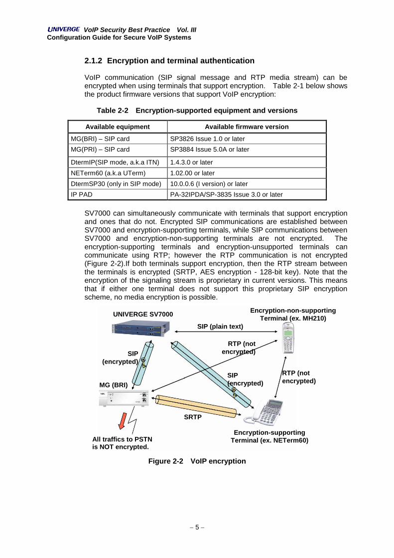
2.1.2 Encryption and terminal authentication
VoIP communication (SIP signal message and RTP media stream) can beencrypted when using terminals that support encryption. Table 2-1 below showsthe product firmware versions that support VoIP encryption:
Table 2-2 Encryption-supported equipment and versions
Available equipment Available firmware version
MG(BRI) – SIP card SP3826 Issue 1.0 or later
MG(PRI) – SIP card SP3884 Issue 5.0A or later
DtermIP(SIP mode, a.k.a ITN) 1.4.3.0 or later
NETerm60 (a.k.a UTerm) 1.02.00 or later
DtermSP30 (only in SIP mode) 10.0.0.6 (I version) or later
IP PAD PA-32IPDA/SP-3835 Issue 3.0 or later
SV7000 can simultaneously communicate with terminals that support encryptionand ones that do not. Encrypted SIP communications are established betweenSV7000 and encryption-supporting terminals, while SIP communications betweenSV7000 and encryption-non-supporting terminals are not encrypted. Theencryption-supporting terminals and encryption-unsupported terminals cancommunicate using RTP; however the RTP communication is not encrypted(Figure 2-2).If both terminals support encryption, then the RTP stream betweenthe terminals is encrypted (SRTP, AES encryption - 128-bit key). Note that theencryption of the signaling stream is proprietary in current versions. This meansthat if either one terminal does not support this proprietary SIP encryptionscheme, no media encryption is possible.
Figure 2-2 VoIP encryption
UNIVERGE SV7000
SIP (plain text)
RTP (notencrypted)
MG (BRI)
All traffics to PSTNis NOT encrypted.
SRTP
Encryption-supportingTerminal (ex. NETerm60)
SIP(encrypted)
Encryption-non-supportingTerminal (ex. MH210)
RTP (notencrypted)
SIP(encrypted)

VoIP Security Best Practice Vol. IIIConfiguration Guide for Secure VoIP Systems
6
2.1.2.1 The encryption key agreement mechanisms
The key agreement mechanisms for SIP encryption are shown in Figure 2-3.These mechanisms are based on NEC proprietary implementation.
Figure 2-3 SIP Key Encryption & Distribution Mechanism
The key agreement mechanisms for SIP encryption consists of these steps:
Step 1. Users configure the “One-time Password (OTP)” to SV7000 andterminals. Configuring such OTP passwords is dependent on theterminal’s implementation as described later under “One-timepassword” configuration.
Step 2. When the SV7000 and the terminals are configured with SIP server,they can communicate and exchange “Terminal Pass” (sharedcredential) using SIP. “Terminal Pass” for each terminal are stored inthe SV7000 and identified by the terminals’ MAC addresses.Terminals have only one “Terminal Pass” per SV7000. The SV7000administrators can confirm which terminals share the “Terminal Pass”using the ASCEL command. The “Terminal Pass” in both SV7000 andthe terminals are not lost even when power is turned off.
Step 3. When a terminal sends the SIP “REGISTRATION” request to theSV7000, the key agreement is negotiated securely using “TerminalPass”. This key is used for SIP encryption.
Step 4. SIP communication between SV7000 and the terminal is encryptedusing the keys exchanged in Step 3. This encryption key is valid untilthe terminal is turned off or restarted. However, such keys areupdated periodically (once a day).
Terminal Authentication
SV7000Negotiation Request
Mutual authentication
Terminal Registration
SV7000
Terminals(DtermIP, NETerm)
Terminals(DtermIP, NETerm)
Terminal Pass One-TimePassword
Authentication Challenge
Encryption key for SIP Signaling
SIP REGISTER message
Registration Request
One-TimePassword
Encryption key isgenerated by using
“Terminal Pass”Encryption key is
generated by using“Terminal Pass”
The “Terminal Pass” is shared by both SV7000 and the terminal in theirfirst communication. (This procedure is normally executed only once.)

VoIP Security Best Practice Vol. IIIConfiguration Guide for Secure VoIP Systems
7
Figure 2-4 Keys and Encryption for SV7000 & Terminals
Figure 2-4 shows keys and credentials used in encrypted VoIP communication.RTP encryption is implemented in conformity with SRTP specification described inRFC3711. RTP encryption key is provided by the SV7000 in encrypted SIPmessages. The RTP encryption key is generated at the SV7000, sent to theterminal in SIP message and used by the terminal. The encryption algorithm isAES and with 128-bits key length. Figure 2-5 shows authentication and SIPencryption key agreement flow. Mutual authentication and SIP encryption keyagreement is done using a 4-way handshake. Both server and clientauthentication use a challenge-response method. Mutual authentication ensuresthat neither the terminal's identity, nor the SV7000's identity can be forged by anattacker. Both parties are completely sure they are communicating with thecorrect counterparts.
SIP encryption is based on NEC proprietary implementation. This implies thatwhen two terminals are involved, both need to support this NEC proprietaryimplementation in order for the RTP media to be encrypted (SRTP) and theconversation to be secured. If either of the two terminals does not support thisproprietary mechanism, no SRTP is supported, thus the conversation is notencrypted/secured.
One-Time Passwordconfiguration
Terminal PassAgreement
SIP Encryption KeyAgreement
RTP Encryption KeyGeneration
OTP OTP
OTPOTP
OTP OTP
OTPTerminal
Pass
TerminalPass
TerminalPass
TerminalPass
TerminalPass
TerminalPass
SIPencryption
key
SIPencryption
key
SIPencryption
key
RTPencryption
key
SIPencryption
key
One-Timepassword
One-Timepassword
Terminal Pass is shared
SIP encryption key is shared
- Terminal Pass is different for every terminal (identified by MAC address).- Terminal Pass is not deleted when terminal/SV7000 is turned off.
- SIP encryption key is shared when the terminal sends SIPRegistration Message.
- Terminal key is used to securely exchange the key.- SIP encryption key is valid while the terminal is is on-line.
- RTP encryption key is generated by SV7000 and sent to the terminal.- RTP encryption key is valid during the call.
OTP
RTP encryption key is sent overencrypted SIP message

VoIP Security Best Practice Vol. IIIConfiguration Guide for Secure VoIP Systems
8
Figure 2-5 Authentication Flow (VoIP encryption enabled)
IP phone SV7000 SP
IP address: 172.16.100.25Number: 8-20-3000
IP address: 192.168.1.2Server-authChallenge
Client-authChallenge
Server-authResponse
Client-authResponse
Encrypted
Encrypted
REGISTER sip:192.168.1.2:5060 SIP/2.0X-Server-Authenticate: Digest realm=“sipterm0001”, nonce=“270b7ab701415ba62eb1d13d94cda9e5”,
opaque=“ET54LxmXl8s8A6zYbywf-s8M00p4MDYU”, stale=FALSE, algorithm=MD5,qop=“auth”
SIP/2.0 401 UnauthorizedWWW-Authenticate: Digest realm=“sipserver0019”, nonce=“fadb376f721d9c18e983aaa960”,
opaque=“6ece8afae0ac7b0f52c8783ca5bd2ed8”, stale=FALSE, algorithm=MD5,qop=“auth”
X-Server-Authorization: Digest realm=“sipterm0001”, nonce=“270b7ab701415ba62eb1d13d94cda9e5”,opaque=“ET54LxmXl8s8A6zYbywf-s8M00p4MDYU”, qop=“auth”, algorithm=MD5,cnonce=“33bd0af5”, nc=00000001,uri=“sip:172.16.100.25:5060”,X-termname=“693bc0a10”
REGISTER sip:192.168.1.2:5060 SIP/2.0Authorization: Digest realm=“sipserver0019”, nonce=“fadb376f721d9c18e983aaa960”,
opaque=“6ece8afae0ac7b0f52c8783ca5bd2ed8”, qop=auth, algorithm=MD5,cnonce=“0D155040”, nc=00000001, uri=“sip:192.168.1.2:5060”,username=“8203000”
SIP/2.0 200 OK

VoIP Security Best Practice Vol. IIIConfiguration Guide for Secure VoIP Systems
9
2.1.2.2 SIP complete encryption and partial encryption
RTP encryption is in conformity with SRTP specification and its mechanism isunique. While SIP encryption has two encryption mechanisms complete andpartial, each mechanism uses the same encryption algorithm (AES, 128 bit keylength). The difference between them lies in which fields are encrypted. AlthoughTLS (Transport Layer Security, defined by RFC2246) recommends securing theSIP standard (defined by RFC3261) connection, NEC’s SIP implementation hasproprietary encryption mechanism. This is because NEC’s SIP communicationuses UDP only as the transport layer protocol.
Complete encryption
Complete SIP message encryption format is shown in Figure 2-6 below. In thiscase, the whole UDP payload is encrypted. Even if malicious users capture thepacket and analyze it, they cannot analyze which application protocol is used.
Figure 2-6 SIP Complete Encryption
Partial encryption
When complete encryption is used, the port numbers in SDP used by RTPcommunication are also encrypted. If there is any NAT or firewall betweenSV7000 and the terminals, NAT or firewall can’t treat the SIP communication andcannot manage the opened/closed ports. To solve this problem, partialencryption mechanism is provided. If the SV7000 is configured to use partialencryption, only NEC original parameters in SIP data field are encrypted. SDPand SIP headers are not encrypted. SIP partial encryption will encrypt the keysthat will be used for the media encryption. So, any intruders/attackers will not beable to read the media encryption keys. As a result, the privacy of voice call ispreserved. SIP partial encryption message format is shown in Figure 2-7.
UDP header
SIP header
CRLF
SIP data(including SDP)
To be encrypted

VoIP Security Best Practice Vol. IIIConfiguration Guide for Secure VoIP Systems
10
Figure 2-7 SIP Partial Encryption
UDP header
SIP header
CRLF
SDPTo be encryptedSIP data
NEC original parameters
VoIP Security Best Practice Vol. IIIConfiguration Guide for Secure VoIP Systems
11
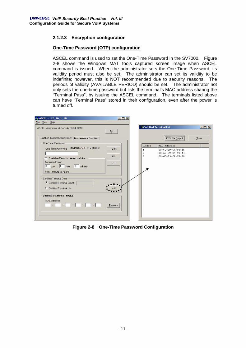
2.1.2.3 Encryption configuration
One-Time Password (OTP) configuration
ASCEL command is used to set the One-Time Password in the SV7000. Figure2-8 shows the Windows MAT tools captured screen image when ASCELcommand is issued. When the administrator sets the One-Time Password, itsvalidity period must also be set. The administrator can set its validity to beindefinite; however, this is NOT recommended due to security reasons. Theperiods of validity (AVAILABLE PERIOD) should be set. The administrator notonly sets the one-time password but lists the terminal’s MAC address sharing the“Terminal Pass”, by issuing the ASCEL command. The terminals listed abovecan have “Terminal Pass” stored in their configuration, even after the power isturned off.
Figure 2-8 One-Time Password Configuration

VoIP Security Best Practice Vol. IIIConfiguration Guide for Secure VoIP Systems
12
Encryption configuration
As described in section 2.1.2.2, there are two mechanisms for SIP encryption.You can select the type of SIP encryption desired using the ASYDL command inthe SV7000 configuration as illustrated bellow:
List 2-1 SV7000 Encryption Configuration
Bit 4 should always be set to “1” (Terminal authentication is enabled). Theparameter for SIP encryption method is INDEX 831 with possible values, “18”(complete encryption) or “10” (partial encryption).
Figure 2-9 SV7000 Encryption Configuration(Left: Complete Encryption, Right: Partial Encryption)
ASYDL system dataSYS1INDEX 831bit 3
SIP communication is encrypted completely.(0/1 = complete encryption/partial encryption)
bit 4Terminal authentication (0/1 = Terminal authentication is disabled/enabled)

VoIP Security Best Practice Vol. IIIConfiguration Guide for Secure VoIP Systems
13
2.2 IP Phone Terminal
This section describes the IP phone configuration for secure VoIP system.These configurations are applicable for SIP-enabled device, since SIP issupposedly used in this practice as the call signaling protocol.
2.2.1 DtermIP (SIP)
DtermIP (SIP mode) also supports VoIP encryption. It also supports the terminalauthentication mechanism.
2.2.1.1 Terminal Authentication Configuration
List 2-2 DtermIP Terminal Authentication Configuration
This configuration is not mandatory. If the User ID and password are not set orentered incorrectly, then a prompt for the correct User ID and password isdisplayed.
2.2.1.2 Encryption Configuration
List 2-3 DtermIP Encryption Configuration
In order to stop VoIP encryption, set “Authentication Mode” to “1. Disabled”.
Configuration Menu2. SIP Settings
1. User1. User ID
User ID → (Input the terminal phone number as the identifier)2. Password
Password → (Input the password set to SV7000)
Configuration Menu2. SIP Settings
6. Encryption1. Authentication Mode
2. Enabled2. One Time Password
One Time Password → (Input the one-time password set to SV7000)

VoIP Security Best Practice Vol. IIIConfiguration Guide for Secure VoIP Systems
14
2.2.1.3 Registrar Destination configuration
If the SV7000 is behind a NAT device (router/firewall), then the IP address, beingspecified by the client as the SIP server, is different from the SV7000 SP(Signaling Processor)’s IP address. (Figure 2-10)
Figure 2-10 SV7000 Access via NAT device
The registrar destination configuration is used in this case. NAT address is setas the SIP server address, and SV7000 SP’s address is set as the registrardestination.
List 2-4 DtermIP Registrar Destination Configuration
Note that the extra configuration is not needed when the terminals are behind theNAT.
SIP server address :10.10.3.2
SIP server address :10.200.200.2
SIP server address :10.200.200.2
Destination IP address istranslated by NAT.
NAT box
Configuration Menu2. SIP Settings
2. Server Address & URI1. 1st Server → (Input NAT’s IP address)5. RegistrarDestination
1. 1st Server → (Input the SV7000 SP’s IP address)
VoIP Security Best Practice Vol. IIIConfiguration Guide for Secure VoIP Systems
15
2.2.2 UTerm (NETerm60)
Uterm (sold as “NEterm 60” in Japan) is an encryption-supporting terminal. Italso supports the terminal authentication mechanism.
2.2.2.1 Terminal authentication configuration
** Detailed configuration can be obtained from the corresponding manuals **
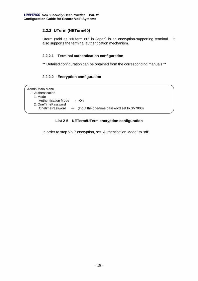
2.2.2.2 Encryption configuration
List 2-5 NETerm/UTerm encryption configuration
In order to stop VoIP encryption, set “Authentication Mode” to “off”.
Admin Main Menu8. Authentication
1. ModeAuthentication Mode → On
2. OneTimePasswordOnetimePassword → (Input the one-time password set to SV7000)
VoIP Security Best Practice Vol. IIIConfiguration Guide for Secure VoIP Systems
16
2.2.2.3 Registrar Destination configuration
In the case of SV7000 access via NAT (Figure 2-10), both SV7000 SP’s addressand NAT address must be specified. The UTerm user can specify the SIPserver’s address by using function keys, but they cannot specify registrardestination address. The “VTConfig” program must be used in this case.
Figure 2-11 VTConfig Interface
Registrar Destination configuration is shown in Figure 2-11.
VTConfig uses SIP, SDP and RTP as the communication protocol. If there is anyfirewall in between NETerm/UTerm and the PC running VTConfig, the firewallmust be configured to allow such communication.
2.2.3 DtermSP30
DtermSP30 also supports VoIP encryption.
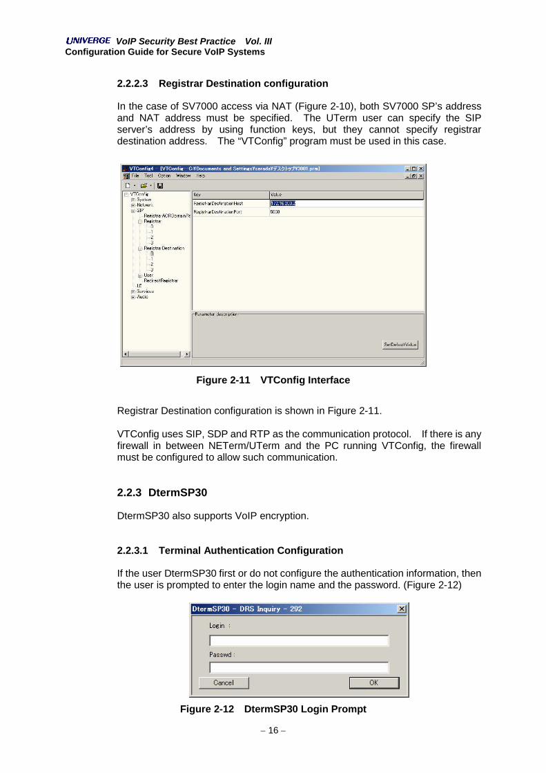
2.2.3.1 Terminal Authentication Configuration
If the user DtermSP30 first or do not configure the authentication information, thenthe user is prompted to enter the login name and the password. (Figure 2-12)
Figure 2-12 DtermSP30 Login Prompt

VoIP Security Best Practice Vol. IIIConfiguration Guide for Secure VoIP Systems
17
The user can enter the login mane and the password every time he/she uses theDtermSP30. These values can be set statically in the DtermSP30 in order to loginautomatically as soon as the DtermSP30 is launched (this feature is called as“Autologin”). In order to configure the “Autologin” feature, use the followingcommands:
1. Select the Config setting button.2. Select the “User” tab from the dialog box.3. Check the “AutoLogin” checkbox and enter the “LoginID” and “Password”.
(Figure 2-13)
Figure 2-13 DtermSP30 “Autologin” Configuration
2.2.3.2 Encryption Configuration
Using DtermSP30Config program, the user can set whether he/she uses the VoIPencryption mechanism or not. If he/she wants to encrypt the communications, puta checkmark in the checkbox as shown in Figure 2-14. Unlike other terminals,DtermSP30 does not require setting the “One-Time Password”. This is due to thedifference in the key exchange mechanism between the DtermSP30 and the otherterminal products. Although the key exchange mechanism is slightly different, theregistration message flow and encryption mechanism is completely the same.

VoIP Security Best Practice Vol. IIIConfiguration Guide for Secure VoIP Systems
18
Figure 2-14 DtermSP30 Encryption Configuration

VoIP Security Best Practice Vol. IIIConfiguration Guide for Secure VoIP Systems
19
2.3 The Other Equipments
2.3.1 MG(BRI)-SIP
2.3.1.1 Encryption configuration
MG(BRI)-SIP supports VoIP encryption. By setting a One-Time Password, VoIPencryption is enabled. To set one-time password, use the “setone_time_password” command as shown below (List 2-6).
List 2-6 MG(BRI)-SIP One-Time Password Configuration
You can confirm that the One-Time Password is set on the MG(BRI)-SIP byissuing the “show one_time_password” command as shown below (List 2-7).Please note that the assigned One-Time Password is deleted from theconfiguration setting when the first registration is completed.
List 2-7 MG(BRI)-SIP One-Time Password Confirmation
-<Configuration mode>Main menu-Standard --- input: 1Custom --- input: 2Quit --- [Q/q]Input: 2
MG-BRI>set one_time_passwordOne Time Password: 11111 ← input the one-time password set to SV7000MG-BRI>save config** Don’t power off in progress **Do you need save? [Y/N]:Y
MG-BRI>show one_time_passwordOne Time Password: 11111

VoIP Security Best Practice Vol. IIIConfiguration Guide for Secure VoIP Systems
20
3. Guideline and Configuration for Firewall and IPNetwork Infrastructure
The security mechanisms and configuration example of each device in networkinfrastructure (described in the second volume) is described in this section.
3.1 Firewall
VoIP communication may be inspected and controlled by a firewall, since suchsystems are built on an existing IP network infrastructure. The firewall can beimplemented in various ways such as an application level gateway, terminationpoint for all TCP and UDP connection, and/or as a traffic filtering device whichinspects and routes all incoming and outgoing packets.
When an organization deploys a VoIP system on existing IP network, the firewallfunction required by the VoIP system can coexist with an existing firewall withoutviolating the organization’s security policy. The firewall devices that have statefulpacket inspection function are now very widely deployed. If stateful inspectiontechnologies are used with VoIP, it has the responsibility to:
Protect from irregular packets which prevents from replay and UDP floodattacks using deep inspection features.
Open and close the necessary UDP ports used by an RTP stream. Theseports are usually closed and are opened when the firewall need to pass RTPstreams.
Not all firewall devices will support NEC’s SIP implementation. The followingfirewall products appear to properly handle NEC’s SIP communication.
Juniper NetScreen firewall Checkpoint firewall-1
In order for the SV7000 and these firewall products to interoperate with VoIPencryption, the system administrator must use SIP Partial Encryption described inchapter 2.1.2.2. If the SIP Complete Encryption is used with these firewalls, thefirewalls may not properly handle the NEC SIP communication thusopening/closing the necessary UDP ports.
No application gateways will support NEC’s SIP implementation at the currentstate. Ingate’s SIParator product has plans to support NEC’s SIP implementationbut its release date is not fixed yet.

VoIP Security Best Practice Vol. IIIConfiguration Guide for Secure VoIP Systems
21
3.1.1 Juniper NetScreen firewall
NetScreen firewall products have not supported NEC’s SIP implementation yet.Juniper and NEC have worked closely to support NEC’s SIP implementations.Final release dates have NOT been completed.
3.1.2 Checkpoint Firewall-1
Checkpoint Firewall-1 has not supported NEC’s SIP implementation yet. As aresult of test with Firewall-1, SV7000 and terminals, some problems were found.Checkpoint and NEC are continuing to work closely in order to fully support NEC’sSIP implementation in the near future. The dates to fully support such NEC SIPimplementation have NOT been finalized yet.

VoIP Security Best Practice Vol. IIIConfiguration Guide for Secure VoIP Systems
22
3.2 IP Network Infrastructure Device
Overview and configuration of the security related functions that are provided bythe network devices (multilayer switch, router, etc), is described in this section.The security related functions, of which the network devices are responsible forare following:
Network Separation (physical/logical) Ingress Filtering System Availability & Uptime
Separation of voice from data traffic can be done via multiple technology methods.One of those methods is using Virtual LAN (VLAN). In this section, only logicalseparation method using VLAN is described. This method is often used to add aVoIP system and equipments to an existing IP data network and cablinginfrastructure.
3.2.1 Layer 2 Switch Configuration (VLAN-based Logical Separation)
In order to mitigate the possibility of Denial-of-Service (DoS) attacks againstservers, and achieving Quality of Service (QoS), corporate networks need to beseparated into a voice and data networks. In other words, traffic needs to beclassified between data and voice. PCs, application and groupware servers areconnected to the data network while the IP-PBX, VoIP gateways and IP phonesare connected to the voice network.
In some cases, some PCs connected to the data network may need tocommunicate with the IP-PBX and VoIP gateways using an installed Softphone(DtermSP30) application. In other cases, PCs are connected to the network viaa layer 2 switch on the IP phone. Under such circumstances, the layer 2 switchmust separate voice from data traffic at a single physical entry port into thenetwork.
Figure 3-1 Network Separation
Data network
Voice network L2SW
Voice and data
Data
Data

VoIP Security Best Practice Vol. IIIConfiguration Guide for Secure VoIP Systems
23
IP phone can insert a VLAN tag into the packets it generates while passingpackets from a PC without inserting any VLAN tag. This allows the network layer 2switches to separate voice from data traffic.
Figure 3-2 PC and IP Phone Connection
3.2.1.1 Cisco Catalyst Switch Series
The following network is considered as an example. Catalyst 2950-24 is used asthe Layer 2 Switch (L2SW).
Figure 3-3 Sample Network with Catalyst Switches
Packet from PC (untagged)
Packet from IP phone (with VLAN-tag)
L2SW
PC and IP phone is connected to single port.
Traffic separation and/or prioritization- interface separation- QoS parameter (Precedence etc) addition- Queuing
All packets are VLAN-taggedVLAN-ID: Voice=201, Data=101
Data and voice core
PC connected via IP-phone
FastEthernet NO.1&2:PC and IP-phone
FastEthernet NO.3: PC
FastEthernet NO.24: upper

VoIP Security Best Practice Vol. IIIConfiguration Guide for Secure VoIP Systems
24
The Catalyst switch in this case should be configured as follow:
List 3-1 Catalyst VLAN-based Network Separation Configuration
When a PC and an IP-phone are connected to single port on the Catalyst L2SWand voice & data traffic are separated by configuration that port as a trunk. In thesample configuration above, VLAN-ID for data and voice are 201 and 101respectively. Since VLAN tag is not attached to data traffic packets, VLAN fordata is specified as the “native” VLAN. Voice and data traffic will be sent to thecore network through interface number 0/24 (FastEthernet0/24). VLAN tag isattached to all packets from/to FastEthernet0/24. QoS-related parameters (mlscommand, priority-queue command and so on) must be configured; suchconfiguration is left out from this example. Please check the proper referencesfor QoS configuration guideline and examples. Please be sure to configureQoS-related parameters in every case.
...interface FastEthernet0/1description IPphoneswitchport trunk encapsulation dot1qswitchport trunk native vlan 101switchport trunk allowed vlan 101,201switchport mode trunk
!interface FastEthernet0/2description IPphoneswitchport trunk encapsulation dot1qswitchport trunk native vlan 101switchport trunk allowed vlan 101,201switchport mode trunk
!interface FastEthernet0/3description DataPCswitchport access vlan 101switchport mode access
!interface FastEthernet0/4...interface FastEthernet0/24description Uplinkswitchport trunk encapsulation dot1qswitchport trunk allowed vlan 101,201switchport mode trunk
...
VoIP Security Best Practice Vol. IIIConfiguration Guide for Secure VoIP Systems
25
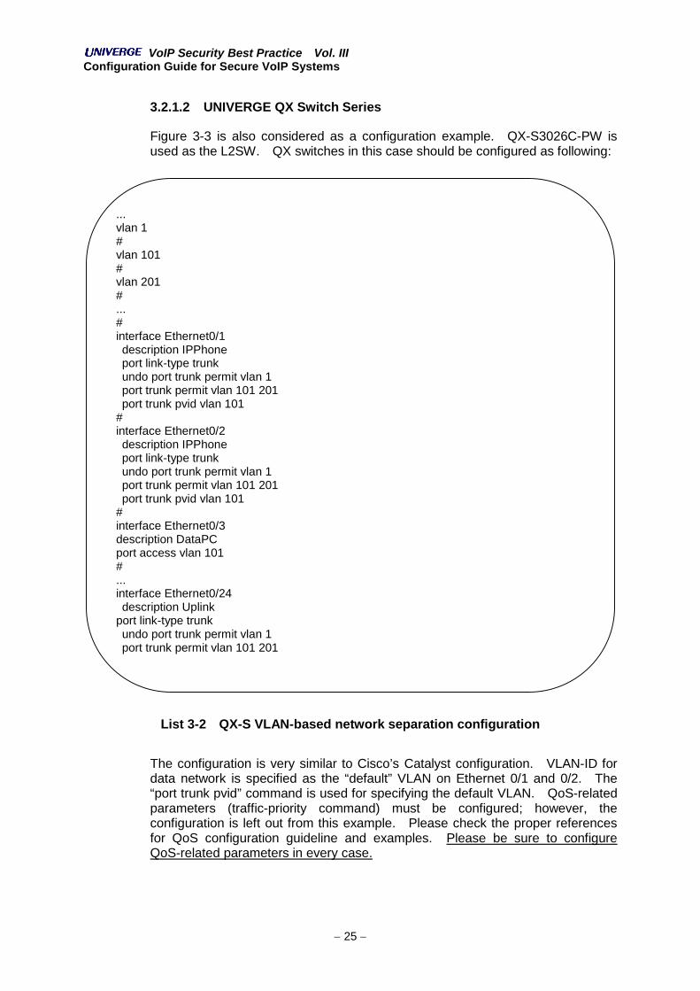
3.2.1.2 UNIVERGE QX Switch Series
Figure 3-3 is also considered as a configuration example. QX-S3026C-PW isused as the L2SW. QX switches in this case should be configured as following:
List 3-2 QX-S VLAN-based network separation configuration
The configuration is very similar to Cisco’s Catalyst configuration. VLAN-ID fordata network is specified as the “default” VLAN on Ethernet 0/1 and 0/2. The“port trunk pvid” command is used for specifying the default VLAN. QoS-relatedparameters (traffic-priority command) must be configured; however, theconfiguration is left out from this example. Please check the proper referencesfor QoS configuration guideline and examples. Please be sure to configureQoS-related parameters in every case.
...vlan 1#vlan 101#vlan 201#...#interface Ethernet0/1description IPPhoneport link-type trunkundo port trunk permit vlan 1port trunk permit vlan 101 201port trunk pvid vlan 101
#interface Ethernet0/2description IPPhoneport link-type trunkundo port trunk permit vlan 1port trunk permit vlan 101 201port trunk pvid vlan 101
#interface Ethernet0/3description DataPCport access vlan 101#...interface Ethernet0/24description Uplink
port link-type trunkundo port trunk permit vlan 1port trunk permit vlan 101 201…

VoIP Security Best Practice Vol. IIIConfiguration Guide for Secure VoIP Systems
26
3.2.1.3 UNIVERGE CX Switch Series
Figure 3-3 is also considered as an example. The UNIVERGE CX-FH5248 is usedas the L2SW. The CX-FH5248 in this case should be configured as follow:
List 3-3 CX-FH5248 VLAN-based network separation
QoS-related parameters (“config qos enable”, “class-map”, and “policy-map”commands) must be configured; however, the configuration is left out from thisexample. Please check the proper references for QoS configuration guideline andexamples. Please be sure to configure QoS-related parameters in every case.
3.2.1.4 BF210/24 Switch
Figure 3-3 is also considered as an example. The BF210/24 is used as theL2SW. The BF210 switch in this case should be configured as following:
List 3-4 BF210/24 VLAN-based network separation
QoS-related parameters (“create access profile” command) must be configured;however, the configuration is left out here. Please check the proper referencesfor QoS configuration guideline and examples. Please be sure to configureQoS-related parameters in every case.
...# VLANcreate vlan default delete 1-24
create vlan VLAN101 tag 101create vlan VLAN201 tag 201
config vlan VLAN101 add tagged 24config vlan VLAN101 add untagged 1,2,3config vlan VLAN201 add tagged 1,2,24...
...interface vlan vlan101 101add port 1/52 taggedadd port 1/1-3 untaggedexitinterface vlan vlan201 201add port 1/1-2 taggedadd port 1/52 taggedexit…

VoIP Security Best Practice Vol. IIIConfiguration Guide for Secure VoIP Systems
27
3.2.2 Layer 2 switch (802.1X authentication)
Refer to corresponding 802.1X configuration for the different access layer 2switches.

VoIP Security Best Practice Vol. IIIConfiguration Guide for Secure VoIP Systems
28
3.2.3 Router or Layer 3 Switch (RFC2827-based ingress filtering)
To mitigate the possibility of DoS attacks, protection against source IP addressspoofing is required. The most effective countermeasures to IP addressspoofing is ingress filtering (defined in RFC2827).
Consider the following network diagram scenario (Figure 3-4) as an example.
Figure 3-4 Sample Network (Ingress Filtering)
In this example, the client segment is connected to the core network through therouter or Layer 3 switch (L3SW). Ingress filtering works when the Client’s IPpackets source IP address is limited to a certain range. In the example above,the address range (IP subnet) is 10.1.2.0/24.
An ingress filtering configuration example using Cisco’s IOS is shown below:
List 3-5 Ingress Filtering Sample Configuration
access-list 101 permit ip any 10.1.2.0 0.0.0.255access-list 101 deny ip any any...interface Ethernet 0/0
ip address 10.254.1.1 255.255.255.0...interface Ethernet0/1
ip address 10.1.2.254 255.255.255.0ip access-group 101 inip accecc-group 102 out
Ethernet 0/010.254.1.1/24
Router or L3SW L2SW
Ethernet 0/110.1.2.254/24
Client segment: 10.1.2.0/24
Corenetwork
VoIP Security Best Practice Vol. IIIConfiguration Guide for Secure VoIP Systems
29
4. Guideline and Configuration for User AccessInfrastructure
4.1 Remote Access from the Internet
A remote access system, which implements a secure virtual path, may bedeployed to access a VoIP system from a remote site (worker’s home, hotels,etc). A softphone (DtermSP30) and/or wireless phone (MH210 & FOMA/WLANdual mode phone) can work in scenario as long as such secure virtual path iscreated. Secure virtual paths can be setup using many Virtual Private Network(VPN) technologies. Two of such technologies are described below in brief.
4.1.1 IPsec-based Remote Access
When IPsec-based remote access systems are deployed, all IP-based applicationcan be used securely through the IPsec VPN tunnel. Remote users can use theDtermSP30 as if they are connected to intranet directly. When the DtermSP30phone is used through such communication medium (the Internet), networkbandwidth, delay and jitter should be considered as they may seriously influencethe voice communication quality. Based on such network condition, theDtermSP30 may not work very well.
Please refer to the corresponding products manuals for proper and accurateconfiguration.
4.1.2 SSL-based remote access
SSL-based remote access VPN (SSL-VPN) implements secure connectivitywithout utilizing any PC VPN client software. Unlike IPsec-based remote access,SSL-VPN does not support all IP-based applications. Many SSL-VPN vendorsoffer various type of SSL-VPN. Not all SSL-VPN products can support theDtermSP30 (softphone) voice application.
NEC has tested a variety of such solutions. We found that the NetScreen SA/RAcan interoperate with the DtermSP30 without any issues. However, the“NetworkConnect” must be used instead of the SAM (Secure ApplicationManager) (both J-SAM and W-SAM) when using the DtermSP30. Moreover,network quality requirements are more critical when compared with IPsec-basedremote access VPN solutions.
Please refer to the corresponding NetScreen SA/RA product manuals forconfiguration examples and guidelines.

VoIP Security Best Practice Vol. IIIConfiguration Guide for Secure VoIP Systems
30
4.2 Wireless LAN Controller
The MH Wireless 802.11 phones (JustPhone) and WLAN/Cellular dual modephone (ex. FOMA N900iL in Japan) are connected to the in-house VoIPinfrastructure via the WLAN infrastructure. Due to their physical access nature,WLANs are more exposed to security threats than wired LANs. A radio wave fromWLAN access point can be transmitted through a wall, a wooden-door and/or awindow. To mitigate from the possibility of un-authorized access, communicationencryption (layer 2 data) and terminal mutual authentication should be deployedwhen using a WLAN. Such authentication and encryption can not only mitigatefrom potential DoS attacks to the VoIP systems, but also prevent maliciousterminals from connecting to the in-house WLAN and LAN network.
The following encryption and authentication features/algorithms can be used with802.11-based WLAN systems.
- Terminal Authentication SSID Authentication Shared Key Authentication (used with WEP Encryption) MAC address-based Access Control 802.1X and EAP Authentication (EAP-MD5, EAP-LEAP, EAP-TLS,
EAP-TTLS, PEAP)- Communication encryption
WEP (Wired Equivalent Privacy)* 64bits Key Length Encryption* 128bits Key Length Encryption
WPA / TKIP encryption (with integrity check) WPA2 / AES CBC-MAC Protocol (CCMP)
When a WLAN is deployed in a corporate network, 802.1X authentication anddynamic key management mechanism (dynamic WEP, WPA and WPA2) shouldbe used in order to adhere to similar wired LAN security levels. SSID and sharedkey authentication does not provide reliable authentication since WEP does notprovide enough confidentiality due to its poorly designed key managementtechnique. As a result, attackers can easily decrypt encrypted packets. It isrecommended (whenever possible) to use WPA2 encryption in order to providemore secure VoIP communications on WLAN networks. NEC’s UNIVERGE WL(Wireless LAN Infrastructure solutions) series products supports all the abovesecurity features.
The MH200 series phones support WEP (64bits and 128bits key length) andWPA2 for encryption, WPA2 is recommended for secure VoIP communicationsacross WLANs and should be configured as such. In case of using WPA2, digitalcertificate for clients will be installed prior to setting the configuration. Digitalcertificates must be installed via the Web browser management interface.
List 4-1 MH210 WPA2 Settings
MH210 configuration[4] WLAN setting
→ [3] Security mode→ [5] WPA2 EAPTLS

VoIP Security Best Practice Vol. IIIConfiguration Guide for Secure VoIP Systems
31
For additional configuration information on the WLAN Controllers and the MH200,please refer to the corresponding products manuals.
Although choosing a non-NEC WLAN Infrastructure (UNIVERGE WL) solution isalways a possibility, it is important to understand that NEC does not recommendusing the MH Series (JustPhone) and/or dual-mode phones with othermanufacturer’s infrastructure WLAN products. This is due to featuresimplemented on the UNIVERGE WL products that will greatly affect the servicequality (throughput, handover time between APs, and so on) of the wireless voiceterminals. If you deploy NEC’s MH/Dual-Mode series phones with any otherWLAN equipment,, please ensure that it at least supports 802.1X and WPA toprovide the acceptable level of VoIP security across your wireless LAN.