Embed Size (px)
Citation preview
Secure ConvergenceVoIP Security Guidelines with Lucent AES
Page 1 of 36 • Technical Brief
Abstract
Enterasys recognizes the emerging need for securing convergence-based applications;specifically protection for voice traffic in a heterogeneous environment. This documentdefines an introduction to securing SIP-type VoIP products, but does not define the completelock down of the SIP protocol. This document implements Enterasys Networks SecureNetworks solutions to secure voice-based products, which do not support security tech-nologies at the network layer. This is considered a high-level implementation and not anetwork hardening solution.
Introduction
Enterasys’ Secure Networks encompass the strategic considerations necessary to lay thefoundation for providing solutions to the security challenges facing today’s convergedenterprise networks. By understanding the separate subcomponents that create vulnera-bilities, network administrators are able to tailor their specific implementations to bettersuit their current needs. The objective of this paper is to discuss implementation strate-gies that leverage Enterasys secure solutions to protect and mitigate threats against thevoice network, and provide enhanced security to devices that lack security features, suchas IP phones.
Secure Network Secure Convergence Considerations
Network security can not be achieved by simply enabling security features in anticipationthat network resources will be protected. Comprehensive network security involves iden-tifying and determining unused or unnecessary features, which, if enabled, could providea potential hacker critical information about the network and its resources. In addition,these compromised resources could serve as a platform for launching attacks against thenetwork or its users. Many vendors leave non-secure RFC-compliant or proprietary protocolsenabled by default in order to provide convenience for customers. However, convenienceprotocols like telnet and web administration are insecure, leaving the network open forexploits and attacks. These concerns of network vulnerabilities convey that a solid strategymust be created when implementing network security.
16894_9013963_SecTech_TB 5/9/05 9:29 AM Page 1
Page 2 of 36 • Technical Brief
Securing VoIP concepts
The implementation of Enterasys’ security features can prevent VoIP disruption from asecurity perspective. VoIP companies today do not support a robust level of security. Untilr e c e n t l y, they have adopted VPN-encryption routines to help secure voice data in the payload portion of an IP packet. Although this is a start in voice security considerations,vendors have yet to deal with such issues as OS-specific vulnerabilities, worm-based attacks,Denial of Service (DoS) or Distributed Denial of Service (DDoS) exploits.
Secure Networks Policy-Based Solutions
By using Secure Networks policy-based solutions, the administrator can control what packetsare allowed and not allowed on the network. This paper recommends the deployment ofSecure Networks solutions: Acceptable Use Policy and Secure Guest Access to defineorganizational policy roles representing different business uses of the network and itsresources. This is accomplished with the use of a policy solution that maps the “Roles” ofan organization, the “Services” available on the network infrastructure, and the “Rules”that enforce the defined services.
Required Feature Implementation
In addition to Secure Networks policy-based solutions, there are many system- and port-level features that if enabled and properly configured will assist in increasing networks e c u r i t y. It is extremely important to identify what services and network protocols arerequired by users to perform their job functions prior to enforcing a policy or modifyingfeatures and/or protocol states. It is equally important to understand the risks associatedwith leaving services or protocols open to users to potentially exploit. This paper will providemuch greater detail regarding security policy implementation recommendations as well ascover which features and protocols should be enabled or disabled in the network and provide the rationale for doing so.
16894_9013963_SecTech_TB 5/9/05 9:29 AM Page 2
Page 3 of 36 • Technical Brief
I. VoIP Security TestingDescription
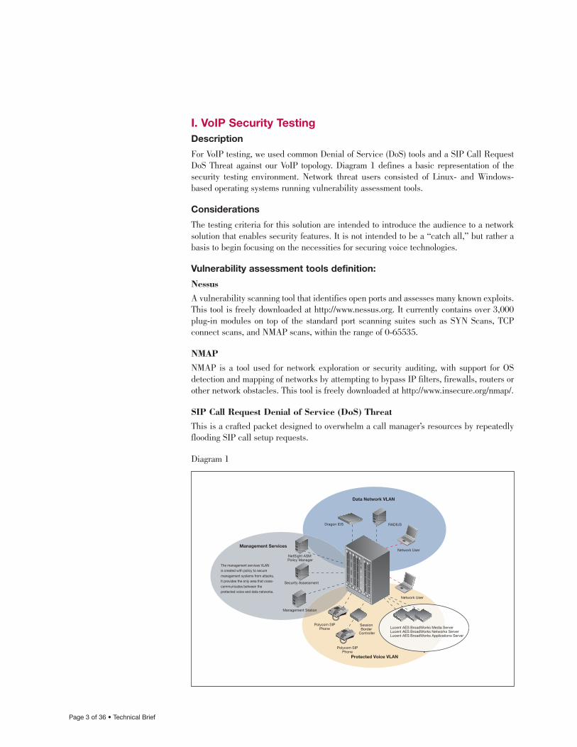
For VoIP testing, we used common Denial of Service (DoS) tools and a SIP Call RequestDoS Threat against our VoIP topology. Diagram 1 defines a basic representation of thesecurity testing environment. Network threat users consisted of Linux- and Windows-based operating systems running vulnerability assessment tools.
Considerations
The testing criteria for this solution are intended to introduce the audience to a networksolution that enables security features. It is not intended to be a “catch all,” but rather abasis to begin focusing on the necessities for securing voice technologies.
Vulnerability assessment tools definition:
NessusA vulnerability scanning tool that identifies open ports and assesses many known exploits.This tool is freely downloaded at http://www.nessus.org. It currently contains over 3,000plug-in modules on top of the standard port scanning suites such as SYN Scans, TCP connect scans, and NMAP scans, within the range of 0-65535.
NMAPNMAP is a tool used for network exploration or security auditing, with support for OSdetection and mapping of networks by attempting to bypass IP filters, firewalls, routers orother network obstacles. This tool is freely downloaded at http://www.insecure.org/nmap/.
SIP Call Request Denial of Service (DoS) ThreatThis is a crafted packet designed to overwhelm a call manager’s resources by repeatedlyflooding SIP call setup requests.
Diagram 1
The management services VLANis created with policy to securemanagement systems from attacks.It provides the only area that cross- communicates between the protected voice and data networks.
NetSight ASM Policy Manager
Lucent AES BroadWorks Media ServerLucent AES BroadWorks Networks ServerLucent AES BroadWorks Applications Server
Security Assessment
Dragon IDS RADIUS
Network UserManagement Services
Data Network VLAN
Protected Voice VLAN
Network User
Polycom SIPPhone
Session Border
Controller
Polycom SIPPhone
Management Station
Page 4 of 36 • Technical Brief
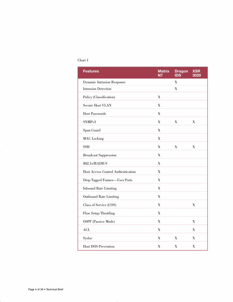
Chart 1
Features Matrix Dragon XSRN7 IDS 3020
Dynamic Intrusion Response X
Intrusion Detection X
Policy (Classification) X
Secure Host VLAN X
Host Passwords X
S N M P v 3 X X X
Span Guard X
MAC Locking X
S S H X X X
Broadcast Suppression X
8 0 2 . 1 x / R A D I U S X
Host Access Control Authentication X
Drop Tagged Frames—User Ports X
Inbound Rate Limiting X
Outbound Rate Limiting X
Class of Service (COS) X X
Flow Setup Throttling X
OSPF (Passive Mode) X X
A C L X X
S y s l o c X X X
Host DOS Prevention X X X
16894_9013963_SecTech_TB 5/9/05 9:30 AM Page 4
Page 5 of 36 • Technical Brief
II. VoIP Security Implementation/Configuration ParametersThis VoIP solution test environment included Enterasys Matrix N-Series switches for the datainfrastructure and NetSight management, integrated with Lucent gateway voice hardware.
Lucent Voice Components
• Lucent AES (BroadSoft) Network Server
• Lucent AES (BroadSoft) Application Server
• Lucent AES (BroadSoft) Media Server
• Polycom SIP Phone Model 600
• Polycom SIP Phone Model 500
• Edgewater Session Border Controller
Enterasys Data Components
• Matrix N7 Platinum, version 4.11.12
Enterasys Security Components
• Dragon IDS Sensor, version 6.3
Matrix N7
• Attack Prevention
— HostDoS Prevention Mechanisms
— Access Control Lists
— Flow Setup Throttling (FST)
— MAC Locking
— V L A N
— A u t h e n t i c a t i o n
— 8 0 2 . 1 x
— MAC Authentication
— R A D I U S
• A u d i t i n g
— Logging (Layer 2)
— Logging (Layer 3)
• Management Security
— Host Access Control Authentication
— S S H
— S N M P v 3
— Secure Host VLAN
16894_9013963_SecTech_TB 5/9/05 9:30 AM Page 5
Page 6 of 36 • Technical Brief
• Q o S
— Outbound Rate Limiting/Class of Service
— Inbound Rate Limiting/Class of Service
— Broadcast Suppression
— V L A N
• Resiliency and Security
— OSPF (Passive Mode)
— S p a n g u a r d
• Service Security
— Data Provisioning/Class of Service
Dragon IDS Sensor
• Intrusion Detection/Response
• S S H
• S N M P v 3
Secure Networks
• Acceptable Use Policy (AUP)
• Dynamic Intrusion Response (DIR)
• Secure Guest Access (SGA)
NetSight
• Console v1.7
• Policy Manager v1.7
• Automated Security Manager v1.1
Firewall
• If applicable; Enterasys does not support SIP on the XSR.
16894_9013963_SecTech_TB 5/9/05 9:30 AM Page 6
Page 7 of 36 • Technical Brief
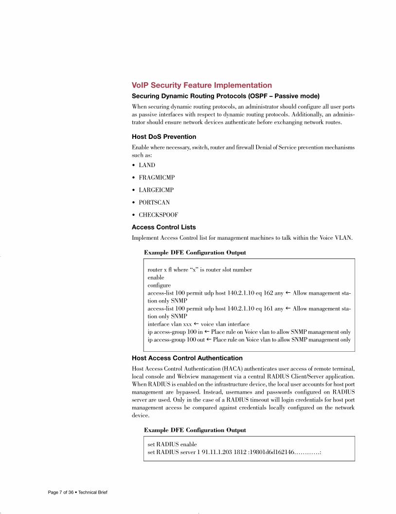
VoIP Security Feature ImplementationSecuring Dynamic Routing Protocols (OSPF – Passive mode)
When securing dynamic routing protocols, an administrator should configure all user portsas passive interfaces with respect to dynamic routing protocols. Additionally, an adminis-trator should ensure network devices authenticate before exchanging network routes.
Host DoS Prevention
Enable where necessary, switch, router and firewall Denial of Service prevention mechanismssuch as:
• L A N D
• F R A G M I C M P
• L A R G E I C M P
• P O RT S C A N
• C H E C K S P O O F
Access Control Lists
Implement Access Control list for management machines to talk within the Voice VLAN.
Example DFE Configuration Output
Host Access Control Authentication
Host Access Control Authentication (HACA) authenticates user access of remote terminal,local console and Webview management via a central RADIUS Client/Server application.When RADIUS is enabled on the infrastructure device, the local user accounts for host portmanagement are bypassed. Instead, usernames and passwords configured on RADIUSserver are used. Only in the case of a RADIUS timeout will login credentials for host portmanagement access be compared against credentials locally configured on the networkd e v i c e .
Example DFE Configuration Output
router x fl where “x” is router slot numbere n a b l ec o n f i g u r eaccess-list 100 permit udp host 140.2.1.10 eq 162 any f Allow management sta-tion only SNMPaccess-list 100 permit udp host 140.2.1.10 eq 161 any f Allow management sta-tion only SNMPinterface vlan xxx f voice vlan interfaceip access-group 100 in f Place rule on Voice vlan to allow SNMP management onlyip access-group 100 out f Place rule on Voice vlan to allow SNMP management only
set RADIUS enableset RADIUS server 1 91.11.1.203 1812 :19801d6d162146…………:
16894_9013963_SecTech_TB 5/9/05 9:30 AM Page 7
Page 8 of 36 • Technical Brief
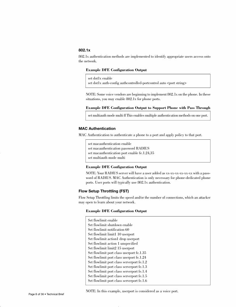
802.1x
802.1x authentication methods are implemented to identify appropriate users access ontothe network.
Example DFE Configuration Output
NOTE: Some voice vendors are beginning to implement 802.1x on the phone. In thesesituations, you may enable 802.1x for phone ports.
Example DFE Configuration Output to Support Phone with Pass Through
MAC Authentication
MAC Authentication to authenticate a phone to a port and apply policy to that port.
Example DFE Configuration Output
NOTE: Your RADIUS server will have a user added as xx-xx-xx-xx-xx-xx with a pass-word of RADIUS. MAC Authentication is only necessary for phone-dedicated phoneports. User ports will typically use 802.1x authentication.
Flow Setup Throttling (FST)
Flow Setup Throttling limits the speed and/or the number of connections, which an attackermay open to learn about your network.
Example DFE Configuration Output
NOTE: In this example, userport is considered as a voice port.
set dot1x enableset dot1x auth-config authcontrolled-portcontrol auto <port string>
set multiauth mode multi fl This enables multiple authentication methods on one port.
set macauthentication enableset macauthentication password RADIUSset macauthentication port enable fe.1.24,35set multiauth mode multi
Set flowlimit enableSet flowlimit shutdown enableSet flowlimit notification 60Set flowlimit limit1 10 userportSet flowlimit action1 drop userportSet flowlimit action 1 unspecifiedSet flowlimit limit2 15 userportSet flowlimit port class userport fe.1.35Set flowlimit port class userport fe.1.24Set flowlimit port class serverport fe.1.2Set flowlimit port class serverport fe.1.3Set flowlimit port class serverport fe.1.4Set flowlimit port class serverport fe.1.5Set flowlimit port class serverport fe.1.6
16894_9013963_SecTech_TB 5/9/05 9:30 AM Page 8
Page 9 of 36 • Technical Brief
MAC Locking
MAC locking enabled to lock the first MAC on the port.
Example DFE Configuration Output
NOTE: Phone port consideration in this case supports a PC pass-through port. Incases where phones do not utilize PC pass-through ports, this value should be set to“1” to be more secure.
Data Provisioning/Class of Service
Provision voice data to have the highest priority on the LAN and network resource data tohave medium priority. All other data will have low priority.
Example DFE Configuration Output
NOTE: This example identifies port 35 as a phone port.
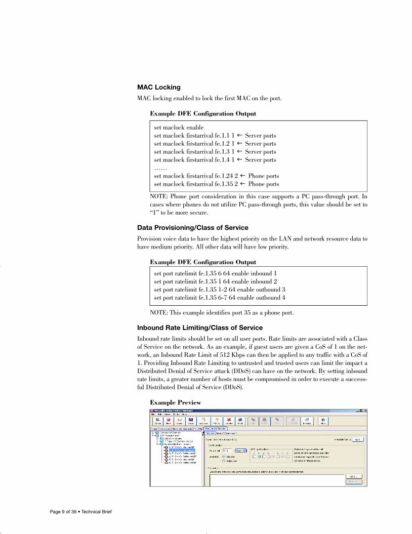
Inbound Rate Limiting/Class of Service
Inbound rate limits should be set on all user ports. Rate limits are associated with a Classof Service on the network. As an example, if guest users are given a CoS of 1 on the net-work, an Inbound Rate Limit of 512 Kbps can then be applied to any traffic with a CoS of1. Providing Inbound Rate Limiting to untrusted and trusted users can limit the impact aDistributed Denial of Service attack (DDoS) can have on the network. By setting inboundrate limits, a greater number of hosts must be compromised in order to execute a success-ful Distributed Denial of Service (DDoS).
Example Preview
set maclock enableset maclock firstarrival fe.1.1 1 f Server portsset maclock firstarrival fe.1.2 1 f Server portsset maclock firstarrival fe.1.3 1 f Server portsset maclock firstarrival fe.1.4 1 f Server ports… …set maclock firstarrival fe.1.24 2 f Phone portsset maclock firstarrival fe.1.35 2 f Phone ports
set port ratelimit fe.1.35 6 64 enable inbound 1set port ratelimit fe.1.35 1 64 enable inbound 2set port ratelimit fe.1.35 1-2 64 enable outbound 3set port ratelimit fe.1.35 6-7 64 enable outbound 4
16894_9013963_SecTech_TB 5/9/05 9:30 AM Page 9
Page 1 0 of 36 • Technical Brief
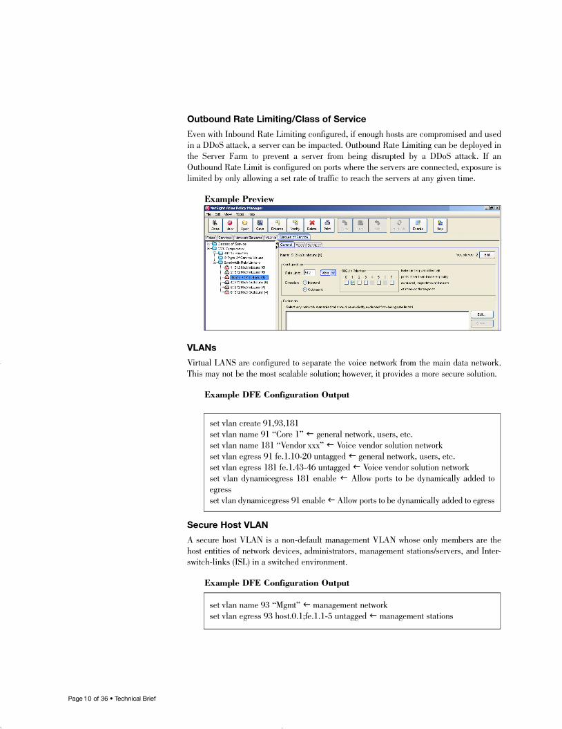
Outbound Rate Limiting/Class of Service
Even with Inbound Rate Limiting configured, if enough hosts are compromised and usedin a DDoS attack, a server can be impacted. Outbound Rate Limiting can be deployed inthe Server Farm to prevent a server from being disrupted by a DDoS attack. If anOutbound Rate Limit is configured on ports where the servers are connected, exposure islimited by only allowing a set rate of traffic to reach the servers at any given time.
Example Preview
VLANs
Virtual LANS are configured to separate the voice network from the main data network.This may not be the most scalable solution; however, it provides a more secure solution.
Example DFE Configuration Output
Secure Host VLAN
A secure host VLAN is a non-default management VLAN whose only members are thehost entities of network devices, administrators, management stations/servers, and Inter-switch-links (ISL) in a switched environment.
Example DFE Configuration Output
set vlan create 91,93,181set vlan name 91 “Core 1” f general network, users, etc.set vlan name 181 “Vendor xxx” f Voice vendor solution networkset vlan egress 91 fe.1.10-20 untagged f general network, users, etc.set vlan egress 181 fe.1.43-46 untagged f Voice vendor solution networkset vlan dynamicegress 181 enable f Allow ports to be dynamically added toe g r e s sset vlan dynamicegress 91 enable fAllow ports to be dynamically added to egress
set vlan name 93 “Mgmt” f management networkset vlan egress 93 host.0.1;fe.1.1-5 untagged f management stations
16894_9013963_SecTech_TB 5/9/05 9:30 AM Page 10
Page 1 1 of 36 • Technical Brief
SSH
SSH was used to secure all communication to the devices. SSH encrypts all traffic (includingpasswords) to eliminate eavesdropping, connection hijacking, and other network-level attacks.
Example DFE Configuration Output
SNMPv3
SNMPv3 should be used on all devices with authentication and privacy passwordsenabled. SNMPv1 should not be used since it is a clear text protocol and susceptible topacket sniffing. If SNMPv1 must be used due to lack of support on legacy devices, ensurethat the default community string is changed to something other than public with read-onlyaccess. If write access is needed when using SNMPv1, a different community string shouldbe used for each device in the network. Only network management stations should havemanagement access via SNMP. All user ports should be configured such that SNMP isexplicitly discarded via policy.
Example DFE Configuration Output
NOTE: 140.2.1.10 is the TRAP server under this testing environment. While noau-thentication is a valid configuration, a stronger configuration will utilize MD5.
RADIUS
When deploying RADIUS authentication, a primary and secondary RADIUS servershould be implemented to prevent a single point of failure. RADIUS is a critical elementwhen using dynamic policies and HACA. Only switch hosts should be allowed to contactthe RADIUS server; all others should be explicitly denied access via policy and ACLdeployment. The RADIUS secret should adhere to the same rules as network passwordsas discussed in the “Passphrase” section.
set ssh enableset ssh hostkey reinitialize
set snmp access gr3 security-model usm noauthentication exact read All write Allnotify Allset snmp group gr3 user bv3 security-model usmset snmp group TrapGroup user TestUser security-model usmset snmp notify TVTr a p Tag tag TVTr a p Ta gset snmp notify bv3notification tag v3bv informset snmp targetaddr TVTrap140.2.1.107TVv1public 140.2.1.107 paramTVv1public taglist TVTr a p Ta gset snmp targetaddr TVTrap192.168.20.57TVv1public 192.168.20.57 paramTVv1public taglist TVTr a p Ta gset snmp targetparams TVv1public user public security-model v1 message-processing v1set snmp view viewname All subtree 1set snmp view viewname All subtree 0.0
16894_9013963_SecTech_TB 5/9/05 9:30 AM Page 11
Page 1 2 of 36 • Technical Brief
Example DFE Configuration Output
NOTE: Lab testing implemented one RADIUS server due to resource restriction.
Spanguard
Spanguard is a means to prevent BPDU (Bridge Protocol Data Unit) spoofing on user ports.When Spanguard is enabled, reception of a BPDU by a port will cause the port to belocked and its state set to blocking. The port will be locked for a globally specified time,which may be forever if the timer value is set to 0. The port will become unlocked whenthe timer expires, it is manually unlocked or the configuration is changed such that eithersecure span is no longer enabled.
Example DFE Configuration Output
Broadcast Suppression
Broadcast Suppression limits the amount of received broadcast frames that the specifiedport is allowed to forward to other ports. Broadcast suppression protects against broadcaststorms, leaving more bandwidth available for critical data.
Example DFE Configuration Output
Logging
SYSLOG messages should be sent to a centralized server. If at all possible, a backup SYS-LOG server should also be implemented in another remote location. This gives the admin-istrator the ability to correlate messages from multiple devices as well as to ensure no logshave been tampered with. SYSLOG provides the information needed to detect and diag-nose a potential break in.
Example DFE Configuration Output
set set RADIUS enableset RADIUS server 1 91.11.1.203 1812 :19801d6d1621…………:
set spantree spanguard enable
set port broadcast fe.1.35-46 50
set snmp access TrapGroup security-model usm privacy exact read allMibs writeallMibs notify allMibsset snmp group TrapGroup user UserName security-model usmset snmp notify TVTr a p Tag tag TVTr a p Ta gset snmp targetaddr TVTrap192.168.20.57TVv1public 192.168.20.57 paramTVv1public taglist TVTr a p Ta gset snmp targetparams TVv1public user public security-model v1 message-pro-cessing v1
16894_9013963_SecTech_TB 5/9/05 9:30 AM Page 12
Page 1 3 of 36 • Technical Brief
Firewall
Implement a firewall with SIP ALG (Application Layer Gateway).
Stream Call Requests
Repetitive call requests to the gateway and/or gatekeeper.
P r o c e d u r e
It is required to capture a call request packet from a phone to the gatekeeper orcall server. This packet is then streamed at higher rates (about 20 percent or moreof a link) to the gatekeeper, call server or other media server to verify the effectson the call processing system. In an unsecured network, the gatekeeper or callserver may exhibit inability to function. With Secure Convergence, the same testwill result in no effect on the gatekeeper or call server to process calls. In somesituations it may be necessary to program Dragon to watch for excessive amountsof call request type packets.
16894_9013963_SecTech_TB 5/9/05 9:30 AM Page 13
Page 1 4 of 36 • Technical Brief
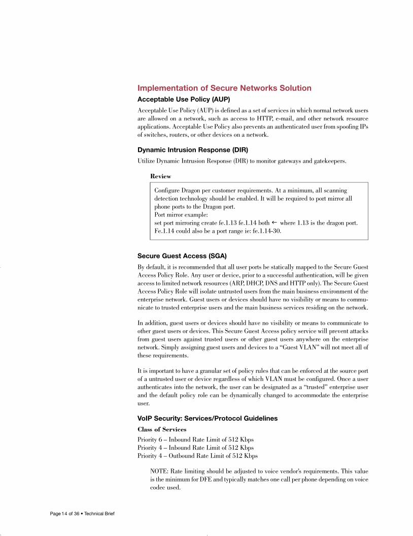
Implementation of Secure Networks SolutionAcceptable Use Policy (AUP)
Acceptable Use Policy (AUP) is defined as a set of services in which normal network usersare allowed on a network, such as access to HTTP, e-mail, and other network resourceapplications. Acceptable Use Policy also prevents an authenticated user from spoofing IPsof switches, routers, or other devices on a network.
Dynamic Intrusion Response (DIR)
Utilize Dynamic Intrusion Response (DIR) to monitor gateways and gatekeepers.
R e v i e w
Secure Guest Access (SGA)
By default, it is recommended that all user ports be statically mapped to the Secure GuestAccess Policy Role. Any user or device, prior to a successful authentication, will be givenaccess to limited network resources (ARP, DHCP, DNS and HTTP only). The Secure GuestAccess Policy Role will isolate untrusted users from the main business environment of theenterprise network. Guest users or devices should have no visibility or means to commu-nicate to trusted enterprise users and the main business services residing on the network.
In addition, guest users or devices should have no visibility or means to communicate toother guest users or devices. This Secure Guest Access policy service will prevent attacksfrom guest users against trusted users or other guest users anywhere on the enterprise network. Simply assigning guest users and devices to a “Guest VLAN” will not meet all ofthese requirements.
It is important to have a granular set of policy rules that can be enforced at the source portof a untrusted user or device regardless of which VLAN must be configured. Once a userauthenticates into the network, the user can be designated as a “trusted” enterprise userand the default policy role can be dynamically changed to accommodate the enterpriseu s e r.
VoIP Security: Services/Protocol Guidelines
Class of ServicesPriority 6 – Inbound Rate Limit of 512 KbpsPriority 4 – Inbound Rate Limit of 512 KbpsPriority 4 – Outbound Rate Limit of 512 Kbps
NOTE: Rate limiting should be adjusted to voice vendor’s requirements. This valueis the minimum for DFE and typically matches one call per phone depending on voicecodec used.
Configure Dragon per customer requirements. At a minimum, all scanningdetection technology should be enabled. It will be required to port mirror allphone ports to the Dragon port.Port mirror example:set port mirroring create fe.1.13 fe.1.14 both f where 1.13 is the dragon port.Fe.1.14 could also be a port range ie: fe.1.14-30.
16894_9013963_SecTech_TB 5/9/05 9:30 AM Page 14

Page 1 5 of 36 • Technical Brief
Deny Spoofing/Administrator Protocols Service“Spoofing” is classic network problem. Spoofing occurs when “user hosts” either inten-tionally or otherwise respond or act as an IT-supported service. Generally, these are Layer4 Sourced or Bidirectional ports, considered reserved for IT or administrative use. Forexample, spurious routing updates are sent to one or more routers causing them to mis-route packets. This differs from a Denial of Service attack only in the purpose behind thespurious route. In Denial of Service, the object is to make the router unusable, a state thatwill be quickly detected by network users. In spoofing, the spurious route will cause packetsto be routed to a host from which an intruder may monitor the data in the packets. Thesepackets are then re-routed to their correct destinations. However, the intruder may or maynot have altered the contents of the packets.
Discard Gateway Source 91.11.1.1 – Router InterfaceDiscard Gateway Source 171.1.0.1 – Router InterfaceDiscard Gateway Source 140.2.1.1 – Router InterfaceDiscard Gateway Source 192.168.2.1 – Router InterfaceDiscard IP Protocol Type OSPFDiscard TCP Bilateral 22 – SSHDiscard TCP Bilateral 23 – Te l n e tDiscard TCP Source 20 – FTP DataDiscard TCP Source 21 – FTPDiscard TCP Source 25 – SMTPDiscard TCP Source 53 – DNS Zone Tr a n s f e r sDiscard TCP Source 443 – SSLDiscard TCP Source 1433 – SQL (Server)Discard UDP Bilateral 69 – TFTPDiscard UDP Bilateral 161 – SNMPDiscard UDP Bilateral 162 – SNMP Tr a p sDiscard UDP Source 53 – DNS ImpostersDiscard UDP Source 520 – RIPDiscard UDP Source 1812 – RADIUSDiscard UDP Source 1813 – RADIUS AccountingDiscard UDP Source 1433 – SQL (Server)
Deny Unsupported ProtocolsDiscard AppleTa l kDiscard AppleTalk ArpsDiscard Banyan Vi n e sDiscard DSAP/SSAP IPXDiscard DSAP/SSAP NetBIOSDiscard DSAP/SSAP SNADiscard Decnet Phase 4Discard IGMPDiscard IPX RIPDiscard Novell IPX1Discard Novell IPX2Discard Reverse ARP
16894_9013963_SecTech_TB 5/9/05 9:30 AM Page 15
Page 1 6 of 36 • Technical Brief
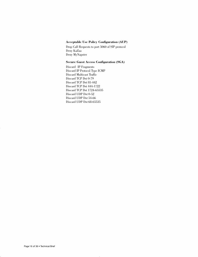
Acceptable Use Policy Configuration (AUP)Drop Call Requests to port 5060 of SIP protocolDeny KaZaaDeny MyNapster
Secure Guest Access Configuration (SGA)D i s c a r d IP FragmentsDiscard IP Protocol Type ICMPDiscard Multicast Tr a f f i cDiscard TCP Dst 0-79Discard TCP Dst 81-442Discard TCP Dst 444-1722Discard TCP Dst 1724-65535Discard UDP Dst 0-52Discard UDP Dst 54-66Discard UDP Dst 68-65535
16894_9013963_SecTech_TB 5/9/05 9:30 AM Page 16
Page 1 7 of 36 • Technical Brief
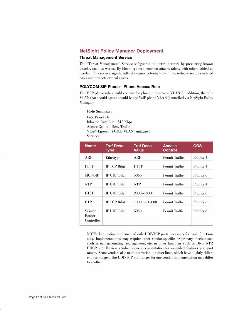
NetSight Policy Manager DeploymentThreat Management Service
The “Threat Management” Service safeguards the entire network by preventing knownattacks, such as worms. By blocking these common attacks (along with others added asneeded), this service significantly decreases potential downtime, reduces security-relatedcosts and protects critical assets.
POLYCOM SIP Phone—Phone Access Role
The VoIP phone role should contain the phone to the voice VLAN. In addition, the onlyVLAN that should egress should be the VoIP phone VLAN (controlled via NetSight PolicyManager).
Role SummaryCoS: Priority 6Inbound Rate Limit 512 KbpsAccess Control: Deny Tr a f f i cVLAN Egress: “VOICE VLAN” untaggedS e r v i c e s :
NOTE: Lab testing implemented only UDP/TCP ports necessary for basic function-a l i t y. Implementations may require other vendor-specific proprietary mechanismssuch as call accounting, management, etc. or other functions such as DNS, NTP,D H C P, etc. Review vendor phone documentation for extended features and portranges. Some vendors also maintain variant product lines, which have slightly differ-ent port ranges. The UDP/TCP port ranges for one vendor implementation may differto another.
Name Traf Desc Traf Desc Access COSType Value Control
A R P E t h e r t y p e A R P Permit Tr a f f i c Priority 4
H T T P IP TCP Bilat H T T P Permit Tr a f f i c Priority 4
M C P - S I P IP UDP Bilat 5 0 6 0 Permit Tr a f f i c Priority 6
N T P IP UDP Bilat N T P Permit Traffic Priority 4
RT C P IP UDP Bilat 2000 – 3000 Permit Tr a f f i c Priority 6
RT P IP TCP Bilat 10000 – 17000 Permit Tr a f f i c Priority 6
Session IP UDP Bilat 5 0 5 0 Permit Tr a f f i c Priority 6Border C o n t r o l l e r
16894_9013963_SecTech_TB 5/9/05 9:30 AM Page 17
Page 1 8 of 36 • Technical Brief
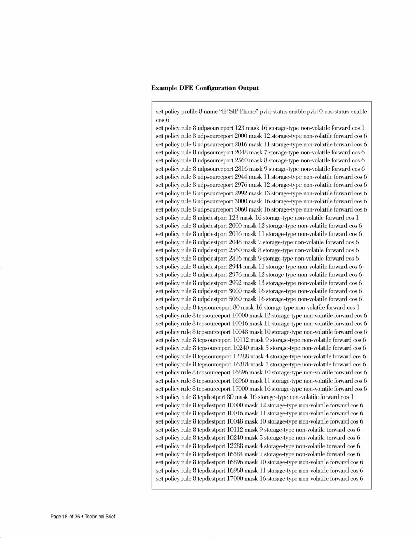
Example DFE Configuration Output
set policy profile 8 name “IP SIP Phone” pvid-status enable pvid 0 cos-status enablecos 6set policy rule 8 udpsourceport 123 mask 16 storage-type non-volatile forward cos 1set policy rule 8 udpsourceport 2000 mask 12 storage-type non-volatile forward cos 6set policy rule 8 udpsourceport 2016 mask 11 storage-type non-volatile forward cos 6set policy rule 8 udpsourceport 2048 mask 7 storage-type non-volatile forward cos 6set policy rule 8 udpsourceport 2560 mask 8 storage-type non-volatile forward cos 6set policy rule 8 udpsourceport 2816 mask 9 storage-type non-volatile forward cos 6set policy rule 8 udpsourceport 2944 mask 11 storage-type non-volatile forward cos 6set policy rule 8 udpsourceport 2976 mask 12 storage-type non-volatile forward cos 6set policy rule 8 udpsourceport 2992 mask 13 storage-type non-volatile forward cos 6set policy rule 8 udpsourceport 3000 mask 16 storage-type non-volatile forward cos 6set policy rule 8 udpsourceport 5060 mask 16 storage-type non-volatile forward cos 6set policy rule 8 udpdestport 123 mask 16 storage-type non-volatile forward cos 1set policy rule 8 udpdestport 2000 mask 12 storage-type non-volatile forward cos 6set policy rule 8 udpdestport 2016 mask 11 storage-type non-volatile forward cos 6set policy rule 8 udpdestport 2048 mask 7 storage-type non-volatile forward cos 6set policy rule 8 udpdestport 2560 mask 8 storage-type non-volatile forward cos 6set policy rule 8 udpdestport 2816 mask 9 storage-type non-volatile forward cos 6set policy rule 8 udpdestport 2944 mask 11 storage-type non-volatile forward cos 6set policy rule 8 udpdestport 2976 mask 12 storage-type non-volatile forward cos 6set policy rule 8 udpdestport 2992 mask 13 storage-type non-volatile forward cos 6set policy rule 8 udpdestport 3000 mask 16 storage-type non-volatile forward cos 6set policy rule 8 udpdestport 5060 mask 16 storage-type non-volatile forward cos 6set policy rule 8 tcpsourceport 80 mask 16 storage-type non-volatile forward cos 1set policy rule 8 tcpsourceport 10000 mask 12 storage-type non-volatile forward cos 6set policy rule 8 tcpsourceport 10016 mask 11 storage-type non-volatile forward cos 6set policy rule 8 tcpsourceport 10048 mask 10 storage-type non-volatile forward cos 6set policy rule 8 tcpsourceport 10112 mask 9 storage-type non-volatile forward cos 6set policy rule 8 tcpsourceport 10240 mask 5 storage-type non-volatile forward cos 6set policy rule 8 tcpsourceport 12288 mask 4 storage-type non-volatile forward cos 6set policy rule 8 tcpsourceport 16384 mask 7 storage-type non-volatile forward cos 6set policy rule 8 tcpsourceport 16896 mask 10 storage-type non-volatile forward cos 6set policy rule 8 tcpsourceport 16960 mask 11 storage-type non-volatile forward cos 6set policy rule 8 tcpsourceport 17000 mask 16 storage-type non-volatile forward cos 6set policy rule 8 tcpdestport 80 mask 16 storage-type non-volatile forward cos 1set policy rule 8 tcpdestport 10000 mask 12 storage-type non-volatile forward cos 6set policy rule 8 tcpdestport 10016 mask 11 storage-type non-volatile forward cos 6set policy rule 8 tcpdestport 10048 mask 10 storage-type non-volatile forward cos 6set policy rule 8 tcpdestport 10112 mask 9 storage-type non-volatile forward cos 6set policy rule 8 tcpdestport 10240 mask 5 storage-type non-volatile forward cos 6set policy rule 8 tcpdestport 12288 mask 4 storage-type non-volatile forward cos 6set policy rule 8 tcpdestport 16384 mask 7 storage-type non-volatile forward cos 6set policy rule 8 tcpdestport 16896 mask 10 storage-type non-volatile forward cos 6set policy rule 8 tcpdestport 16960 mask 11 storage-type non-volatile forward cos 6set policy rule 8 tcpdestport 17000 mask 16 storage-type non-volatile forward cos 6
16894_9013963_SecTech_TB 5/9/05 9:30 AM Page 18
Page 1 9 of 36 • Technical Brief
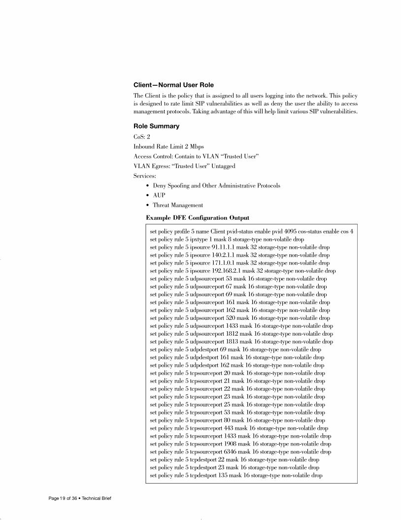
Client—Normal User Role
The Client is the policy that is assigned to all users logging into the network. This policyis designed to rate limit SIP vulnerabilities as well as deny the user the ability to accessmanagement protocols. Taking advantage of this will help limit various SIP vulnerabilities.
Role Summary
CoS: 2Inbound Rate Limit 2 MbpsAccess Control: Contain to VLAN “Trusted User”VLAN Egress: “Trusted User” UntaggedS e r v i c e s :
• Deny Spoofing and Other Administrative Protocols• A U P• Threat Management
Example DFE Configuration Output
set policy profile 5 name Client pvid-status enable pvid 4095 cos-status enable cos 4 set policy rule 5 ipxtype 1 mask 8 storage-type non-volatile dropset policy rule 5 ipsource 91.11.1.1 mask 32 storage-type non-volatile dropset policy rule 5 ipsource 140.2.1.1 mask 32 storage-type non-volatile dropset policy rule 5 ipsource 171.1.0.1 mask 32 storage-type non-volatile dropset policy rule 5 ipsource 192.168.2.1 mask 32 storage-type non-volatile dropset policy rule 5 udpsourceport 53 mask 16 storage-type non-volatile dropset policy rule 5 udpsourceport 67 mask 16 storage-type non-volatile dropset policy rule 5 udpsourceport 69 mask 16 storage-type non-volatile dropset policy rule 5 udpsourceport 161 mask 16 storage-type non-volatile dropset policy rule 5 udpsourceport 162 mask 16 storage-type non-volatile dropset policy rule 5 udpsourceport 520 mask 16 storage-type non-volatile dropset policy rule 5 udpsourceport 1433 mask 16 storage-type non-volatile dropset policy rule 5 udpsourceport 1812 mask 16 storage-type non-volatile dropset policy rule 5 udpsourceport 1813 mask 16 storage-type non-volatile dropset policy rule 5 udpdestport 69 mask 16 storage-type non-volatile dropset policy rule 5 udpdestport 161 mask 16 storage-type non-volatile dropset policy rule 5 udpdestport 162 mask 16 storage-type non-volatile dropset policy rule 5 tcpsourceport 20 mask 16 storage-type non-volatile dropset policy rule 5 tcpsourceport 21 mask 16 storage-type non-volatile dropset policy rule 5 tcpsourceport 22 mask 16 storage-type non-volatile dropset policy rule 5 tcpsourceport 23 mask 16 storage-type non-volatile dropset policy rule 5 tcpsourceport 25 mask 16 storage-type non-volatile dropset policy rule 5 tcpsourceport 53 mask 16 storage-type non-volatile dropset policy rule 5 tcpsourceport 80 mask 16 storage-type non-volatile dropset policy rule 5 tcpsourceport 443 mask 16 storage-type non-volatile dropset policy rule 5 tcpsourceport 1433 mask 16 storage-type non-volatile dropset policy rule 5 tcpsourceport 1908 mask 16 storage-type non-volatile dropset policy rule 5 tcpsourceport 6346 mask 16 storage-type non-volatile dropset policy rule 5 tcpdestport 22 mask 16 storage-type non-volatile dropset policy rule 5 tcpdestport 23 mask 16 storage-type non-volatile dropset policy rule 5 tcpdestport 135 mask 16 storage-type non-volatile drop
16894_9013963_SecTech_TB 5/9/05 9:30 AM Page 19
Page 2 0 of 36 • Technical Brief
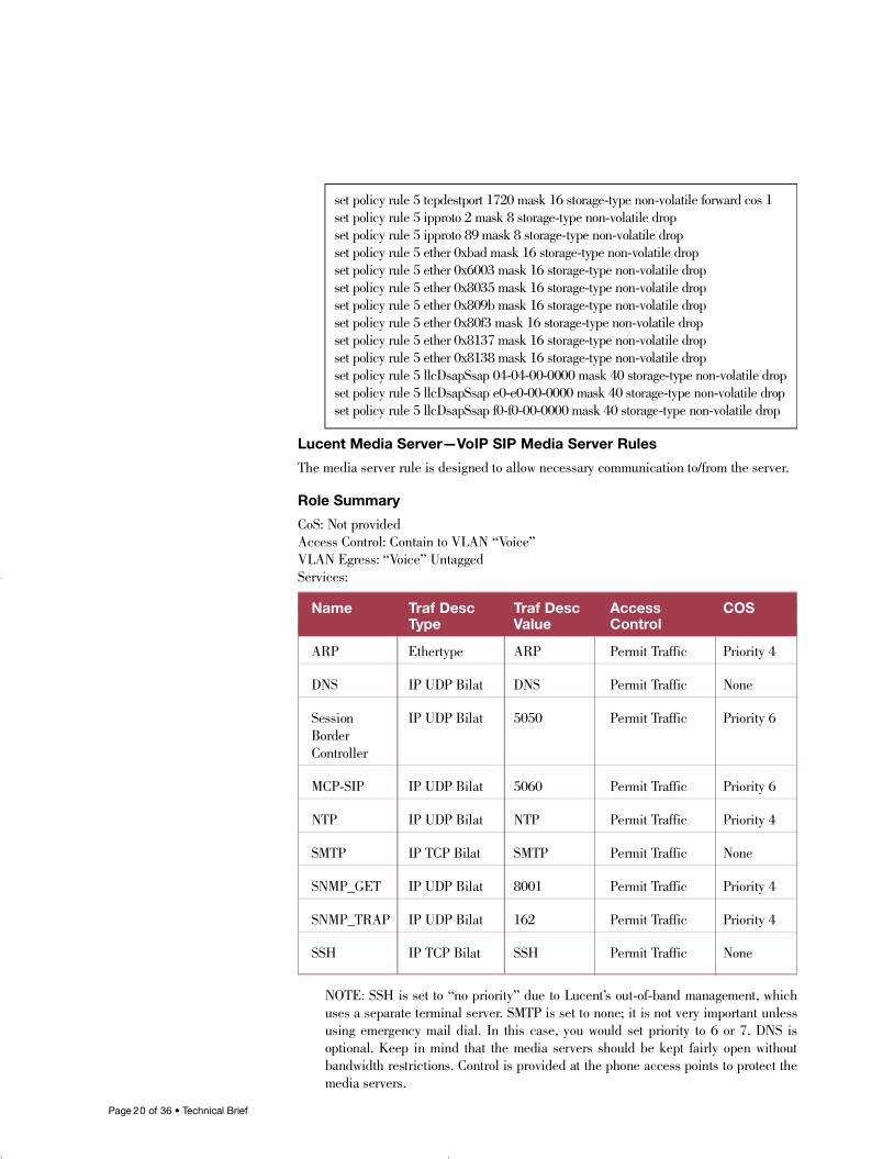
Lucent Media Server—VoIP SIP Media Server Rules
The media server rule is designed to allow necessary communication to/from the server.
Role Summary
CoS: Not providedAccess Control: Contain to VLAN “Vo i c e ”VLAN Egress: “Voice” UntaggedS e r v i c e s :
NOTE: SSH is set to “no priority” due to Lucent’s out-of-band management, whichuses a separate terminal server. SMTP is set to none; it is not very important unlessusing emergency mail dial. In this case, you would set priority to 6 or 7. DNS isoptional. Keep in mind that the media servers should be kept fairly open withoutbandwidth restrictions. Control is provided at the phone access points to protect themedia servers.
set policy rule 5 tcpdestport 1720 mask 16 storage-type non-volatile forward cos 1set policy rule 5 ipproto 2 mask 8 storage-type non-volatile dropset policy rule 5 ipproto 89 mask 8 storage-type non-volatile dropset policy rule 5 ether 0xbad mask 16 storage-type non-volatile dropset policy rule 5 ether 0x6003 mask 16 storage-type non-volatile dropset policy rule 5 ether 0x8035 mask 16 storage-type non-volatile dropset policy rule 5 ether 0x809b mask 16 storage-type non-volatile dropset policy rule 5 ether 0x80f3 mask 16 storage-type non-volatile dropset policy rule 5 ether 0x8137 mask 16 storage-type non-volatile dropset policy rule 5 ether 0x8138 mask 16 storage-type non-volatile dropset policy rule 5 llcDsapSsap 04-04-00-0000 mask 40 storage-type non-volatile dropset policy rule 5 llcDsapSsap e0-e0-00-0000 mask 40 storage-type non-volatile dropset policy rule 5 llcDsapSsap f0-f0-00-0000 mask 40 storage-type non-volatile drop
Name Traf Desc Traf Desc Access COSType Value Control
A R P E t h e r t y p e A R P Permit Tr a f f i c Priority 4
D N S IP UDP Bilat D N S Permit Tr a f f i c N o n e
Session IP UDP Bilat 5 0 5 0 Permit Tr a f f i c Priority 6Border C o n t r o l l e r
M C P - S I P IP UDP Bilat 5 0 6 0 Permit Tr a f f i c Priority 6
N T P IP UDP Bilat N T P Permit Tr a f f i c Priority 4
S M T P IP TCP Bilat S M T P Permit Tr a f f i c N o n e
S N M P _ G E T IP UDP Bilat 8 0 0 1 Permit Tr a f f i c Priority 4
S N M P _ T R A P IP UDP Bilat 1 6 2 Permit Tr a f f i c Priority 4
S S H IP TCP Bilat S S H Permit Tr a f f i c N o n e
16894_9013963_SecTech_TB 5/9/05 9:30 AM Page 20
Page 2 1 of 36 • Technical Brief
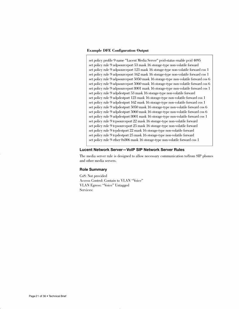
Example DFE Configuration Output
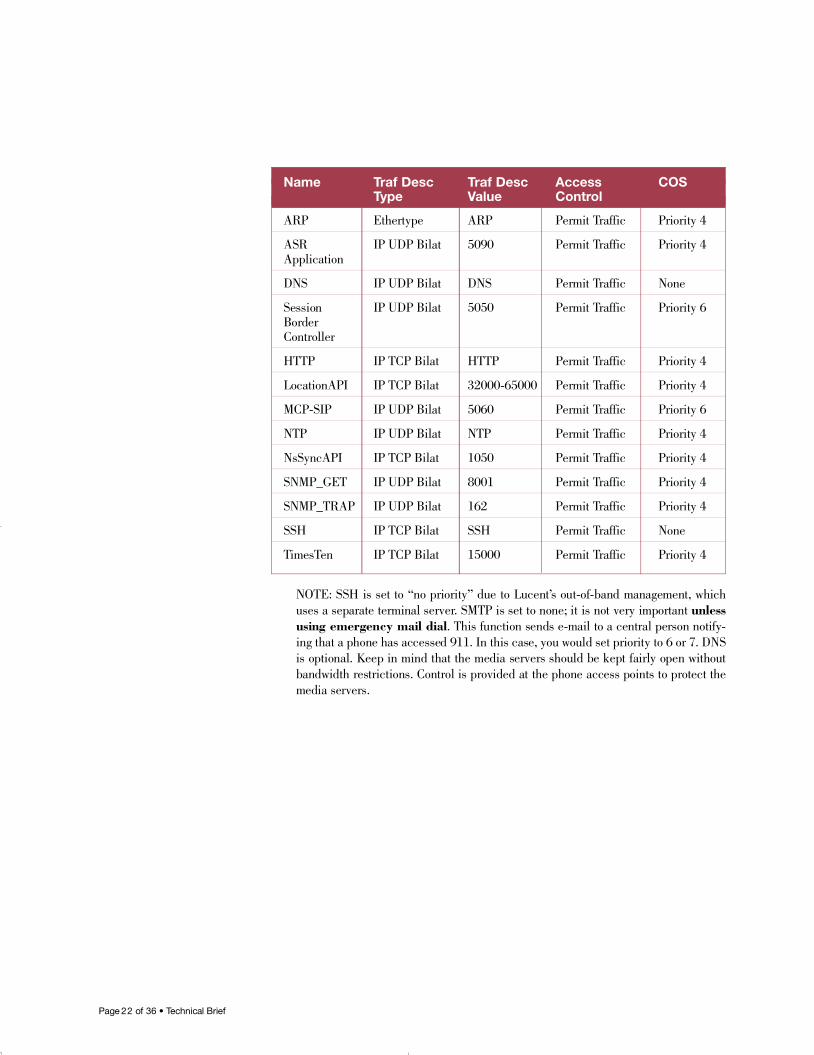
Lucent Network Server—VoIP SIP Network Server Rules
The media server rule is designed to allow necessary communication to/from SIP phonesand other media servers.
Role Summary
CoS: Not providedAccess Control: Contain to VLAN “Vo i c e ”VLAN Egress: “Voice” UntaggedS e r v i c e s :
set policy profile 9 name "Lucent Media Server" pvid-status enable pvid 4095 set policy rule 9 udpsourceport 53 mask 16 storage-type non-volatile forwardset policy rule 9 udpsourceport 123 mask 16 storage-type non-volatile forward cos 1set policy rule 9 udpsourceport 162 mask 16 storage-type non-volatile forward cos 1set policy rule 9 udpsourceport 5050 mask 16 storage-type non-volatile forward cos 6set policy rule 9 udpsourceport 5060 mask 16 storage-type non-volatile forward cos 6set policy rule 9 udpsourceport 8001 mask 16 storage-type non-volatile forward cos 1set policy rule 9 udpdestport 53 mask 16 storage-type non-volatile forwardset policy rule 9 udpdestport 123 mask 16 storage-type non-volatile forward cos 1set policy rule 9 udpdestport 162 mask 16 storage-type non-volatile forward cos 1set policy rule 9 udpdestport 5050 mask 16 storage-type non-volatile forward cos 6set policy rule 9 udpdestport 5060 mask 16 storage-type non-volatile forward cos 6set policy rule 9 udpdestport 8001 mask 16 storage-type non-volatile forward cos 1set policy rule 9 tcpsourceport 22 mask 16 storage-type non-volatile forwardset policy rule 9 tcpsourceport 25 mask 16 storage-type non-volatile forwardset policy rule 9 tcpdestport 22 mask 16 storage-type non-volatile forwardset policy rule 9 tcpdestport 25 mask 16 storage-type non-volatile forwardset policy rule 9 ether 0x806 mask 16 storage-type non-volatile forward cos 1
16894_9013963_SecTech_TB 5/9/05 9:30 AM Page 21
Page 2 2 of 36 • Technical Brief
NOTE: SSH is set to “no priority” due to Lucent’s out-of-band management, whichuses a separate terminal server. SMTP is set to none; it is not very important u n l e s susing emergency mail dial. This function sends e-mail to a central person notify-ing that a phone has accessed 911. In this case, you would set priority to 6 or 7. DNSis optional. Keep in mind that the media servers should be kept fairly open withoutbandwidth restrictions. Control is provided at the phone access points to protect themedia servers.
Name Traf Desc Traf Desc Access COSType Value Control
A R P E t h e r t y p e A R P Permit Tr a f f i c Priority 4
ASR IP UDP Bilat 5 0 9 0 Permit Tr a f f i c Priority 4A p p l i c a t i o n
D N S IP UDP Bilat D N S Permit Tr a f f i c N o n e
Session IP UDP Bilat 5 0 5 0 Permit Tr a f f i c Priority 6Border C o n t r o l l e r
H T T P IP TCP Bilat H T T P Permit Tr a f f i c Priority 4
L o c a t i o n A P I IP TCP Bilat 3 2 0 0 0 - 6 5 0 0 0 Permit Tr a f f i c Priority 4
M C P - S I P IP UDP Bilat 5 0 6 0 Permit Tr a f f i c Priority 6
N T P IP UDP Bilat N T P Permit Tr a f f i c Priority 4
N s S y n c A P I IP TCP Bilat 1 0 5 0 Permit Tr a f f i c Priority 4
S N M P _ G E T IP UDP Bilat 8 0 0 1 Permit Tr a f f i c Priority 4
S N M P _ T R A P IP UDP Bilat 1 6 2 Permit Tr a f f i c Priority 4
S S H IP TCP Bilat S S H Permit Tr a f f i c N o n e
Ti m e s Te n IP TCP Bilat 1 5 0 0 0 Permit Traffic Priority 4
16894_9013963_SecTech_TB 5/9/05 9:30 AM Page 22

Page 2 3 of 36 • Technical Brief
Example DFE Configuration Output
set policy profile 10 name "Lucent Network Server" pvid-status enable pvid 4095 set policy rule 10 udpsourceport 53 mask 16 storage-type non-volatile forwardset policy rule 10 udpsourceport 123 mask 16 storage-type non-volatile forward cos 1set policy rule 10 udpsourceport 162 mask 16 storage-type non-volatile forward cos 1set policy rule 10 udpsourceport 5050 mask 16 storage-type non-volatile forward cos 6set policy rule 10 udpsourceport 5060 mask 16 storage-type non-volatile forward cos 6set policy rule 10 udpsourceport 5090 mask 16 storage-type non-volatile forward cos 1set policy rule 10 udpsourceport 8001 mask 16 storage-type non-volatile forward cos 1set policy rule 10 udpdestport 53 mask 16 storage-type non-volatile forwardset policy rule 10 udpdestport 123 mask 16 storage-type non-volatile forward cos 1set policy rule 10 udpdestport 162 mask 16 storage-type non-volatile forward cos 1set policy rule 10 udpdestport 5050 mask 16 storage-type non-volatile forward cos 6set policy rule 10 udpdestport 5060 mask 16 storage-type non-volatile forward cos 6set policy rule 10 udpdestport 5090 mask 16 storage-type non-volatile forward cos 1set policy rule 10 udpdestport 8001 mask 16 storage-type non-volatile forward cos 1set policy rule 10 tcpsourceport 22 mask 16 storage-type non-volatile forwardset policy rule 10 tcpsourceport 80 mask 16 storage-type non-volatile forward cos 1set policy rule 10 tcpsourceport 1050 mask 16 storage-type non-volatile forward cos 1set policy rule 10 tcpsourceport 15000 mask 16 storage-type non-volatile forward cos 1set policy rule 10 tcpsourceport 32000 mask 8 storage-type non-volatile forward cos 1set policy rule 10 tcpsourceport 32256 mask 7 storage-type non-volatile forward cos 1set policy rule 10 tcpsourceport 32768 mask 2 storage-type non-volatile forward cos 1set policy rule 10 tcpsourceport 49152 mask 3 storage-type non-volatile forward cos 1set policy rule 10 tcpsourceport 57344 mask 4 storage-type non-volatile forward cos 1set policy rule 10 tcpsourceport 61440 mask 5 storage-type non-volatile forward cos 1set policy rule 10 tcpsourceport 63488 mask 6 storage-type non-volatile forward cos 1set policy rule 10 tcpsourceport 64512 mask 8 storage-type non-volatile forward cos 1set policy rule 10 tcpsourceport 64768 mask 9 storage-type non-volatile forward cos 1set policy rule 10 tcpsourceport 64896 mask 10 storage-type non-volatile forward cos 1set policy rule 10 tcpsourceport 64960 mask 11 storage-type non-volatile forward cos 1set policy rule 10 tcpsourceport 64992 mask 13 storage-type non-volatile forward cos 1set policy rule 10 tcpsourceport 65000 mask 16 storage-type non-volatile forward cos 1set policy rule 10 tcpdestport 22 mask 16 storage-type non-volatile forwardset policy rule 10 tcpdestport 80 mask 16 storage-type non-volatile forward cos 1set policy rule 10 tcpdestport 1050 mask 16 storage-type non-volatile forward cos 1set policy rule 10 tcpdestport 15000 mask 16 storage-type non-volatile forward cos 1set policy rule 10 tcpdestport 32000 mask 8 storage-type non-volatile forward cos 1set policy rule 10 tcpdestport 32256 mask 7 storage-type non-volatile forward cos 1set policy rule 10 tcpdestport 32768 mask 2 storage-type non-volatile forward cos 1set policy rule 10 tcpdestport 49152 mask 3 storage-type non-volatile forward cos 1set policy rule 10 tcpdestport 57344 mask 4 storage-type non-volatile forward cos 1set policy rule 10 tcpdestport 61440 mask 5 storage-type non-volatile forward cos 1set policy rule 10 tcpdestport 63488 mask 6 storage-type non-volatile forward cos 1set policy rule 10 tcpdestport 64512 mask 8 storage-type non-volatile forward cos 1set policy rule 10 tcpdestport 64768 mask 9 storage-type non-volatile forward cos 1set policy rule 10 tcpdestport 64896 mask 10 storage-type non-volatile forward cos 1set policy rule 10 tcpdestport 64960 mask 11 storage-type non-volatile forward cos 1set policy rule 10 tcpdestport 64992 mask 13 storage-type non-volatile forward cos 1set policy rule 10 tcpdestport 65000 mask 16 storage-type non-volatile forward cos 1set policy rule 10 ether 0x806 mask 16 storage-type non-volatile forward cos 1
16894_9013963_SecTech_TB 5/9/05 9:30 AM Page 23
Page 2 4 of 36 • Technical Brief
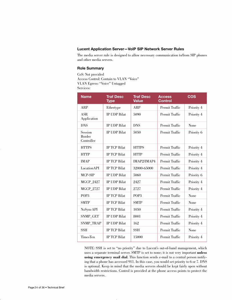
Lucent Application Server—VoIP SIP Network Server Rules
The media server rule is designed to allow necessary communication to/from SIP phonesand other media servers.
Role Summary
CoS: Not providedAccess Control: Contain to VLAN “Vo i c e ”VLAN Egress: “Voice” UntaggedS e r v i c e s :
NOTE: SSH is set to “no priority” due to Lucent’s out-of-band management, whichuses a separate terminal server. SMTP is set to none; it is not very important u n l e s susing emergency mail dial. This function sends e-mail to a central person notify-ing that a phone has accessed 911. In this case, you would set priority to 6 or 7. DNSis optional. Keep in mind that the media servers should be kept fairly open withoutbandwidth restrictions. Control is provided at the phone access points to protect themedia servers.
Name Traf Desc Traf Desc Access COSType Value Control
A R P E t h e r t y p e A R P Permit Tr a f f i c Priority 4
ASR IP UDP Bilat 5 0 9 0 Permit Tr a f f i c Priority 4A p p l i c a t i o n
D N S IP UDP Bilat D N S Permit Tr a f f i c N o n e
Session IP UDP Bilat 5 0 5 0 Permit Tr a f f i c Priority 6Border C o n t r o l l e r
H T T P S IP TCP Bilat H T T P S Permit Tr a f f i c Priority 4
H T T P IP TCP Bilat H T T P Permit Tr a f f i c Priority 4
I M A P IP TCP Bilat I M A P 2 / I M A P 4 Permit Tr a f f i c Priority 4
L o c a t i o n A P I IP TCP Bilat 3 2 0 0 0 - 6 5 0 0 0 Permit Tr a f f i c Priority 4
M C P - S I P IP UDP Bilat 5 0 6 0 Permit Tr a f f i c Priority 6
M G C P _ 2 4 2 7 IP UDP Bilat 2 4 2 7 Permit Tr a f f i c Priority 4
M G C P _ 2 7 2 7 IP UDP Bilat 2 7 2 7 Permit Tr a f f i c Priority 4
P O P 3 IP TCP Bilat P O P 3 Permit Tr a f f i c N o n e
S M T P IP TCP Bilat S M T P Permit Tr a f f i c N o n e
N s S y n c A P I IP TCP Bilat 1 0 5 0 Permit Tr a f f i c Priority 4
S N M P _ G E T IP UDP Bilat 8 0 0 1 Permit Tr a f f i c Priority 4
S N M P _ T R A P IP UDP Bilat 1 6 2 Permit Tr a f f i c Priority 4
S S H IP TCP Bilat S S H Permit Tr a f f i c N o n e
Ti m e s Te n IP TCP Bilat 1 5 0 0 0 Permit Traffic Priority 4
16894_9013963_SecTech_TB 5/9/05 9:30 AM Page 24
Page 2 5 of 36 • Technical Brief
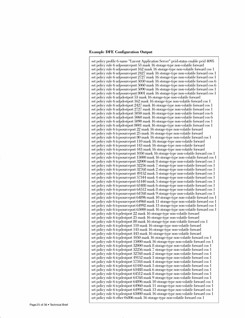
Example DFE Configuration Output
set policy profile 6 name "Lucent Application Server" pvid-status enable pvid 4095 set policy rule 6 udpsourceport 53 mask 16 storage-type non-volatile forwardset policy rule 6 udpsourceport 162 mask 16 storage-type non-volatile forward cos 1set policy rule 6 udpsourceport 2427 mask 16 storage-type non-volatile forward cos 1set policy rule 6 udpsourceport 2727 mask 16 storage-type non-volatile forward cos 1set policy rule 6 udpsourceport 5050 mask 16 storage-type non-volatile forward cos 6set policy rule 6 udpsourceport 5060 mask 16 storage-type non-volatile forward cos 6set policy rule 6 udpsourceport 5090 mask 16 storage-type non-volatile forward cos 1set policy rule 6 udpsourceport 8001 mask 16 storage-type non-volatile forward cos 1set policy rule 6 udpdestport 53 mask 16 storage-type non-volatile forwardset policy rule 6 udpdestport 162 mask 16 storage-type non-volatile forward cos 1set policy rule 6 udpdestport 2427 mask 16 storage-type non-volatile forward cos 1set policy rule 6 udpdestport 2727 mask 16 storage-type non-volatile forward cos 1set policy rule 6 udpdestport 5050 mask 16 storage-type non-volatile forward cos 6set policy rule 6 udpdestport 5060 mask 16 storage-type non-volatile forward cos 6set policy rule 6 udpdestport 5090 mask 16 storage-type non-volatile forward cos 1set policy rule 6 udpdestport 8001 mask 16 storage-type non-volatile forward cos 1set policy rule 6 tcpsourceport 22 mask 16 storage-type non-volatile forwardset policy rule 6 tcpsourceport 25 mask 16 storage-type non-volatile forwardset policy rule 6 tcpsourceport 80 mask 16 storage-type non-volatile forward cos 1set policy rule 6 tcpsourceport 110 mask 16 storage-type non-volatile forwardset policy rule 6 tcpsourceport 143 mask 16 storage-type non-volatile forwardset policy rule 6 tcpsourceport 443 mask 16 storage-type non-volatile forwardset policy rule 6 tcpsourceport 1050 mask 16 storage-type non-volatile forward cos 1set policy rule 6 tcpsourceport 15000 mask 16 storage-type non-volatile forward cos 1set policy rule 6 tcpsourceport 32000 mask 8 storage-type non-volatile forward cos 1set policy rule 6 tcpsourceport 32256 mask 7 storage-type non-volatile forward cos 1set policy rule 6 tcpsourceport 32768 mask 2 storage-type non-volatile forward cos 1set policy rule 6 tcpsourceport 49152 mask 3 storage-type non-volatile forward cos 1set policy rule 6 tcpsourceport 57344 mask 4 storage-type non-volatile forward cos 1set policy rule 6 tcpsourceport 61440 mask 5 storage-type non-volatile forward cos 1set policy rule 6 tcpsourceport 63488 mask 6 storage-type non-volatile forward cos 1set policy rule 6 tcpsourceport 64512 mask 8 storage-type non-volatile forward cos 1set policy rule 6 tcpsourceport 64768 mask 9 storage-type non-volatile forward cos 1set policy rule 6 tcpsourceport 64896 mask 10 storage-type non-volatile forward cos 1set policy rule 6 tcpsourceport 64960 mask 11 storage-type non-volatile forward cos 1set policy rule 6 tcpsourceport 64992 mask 13 storage-type non-volatile forward cos 1set policy rule 6 tcpsourceport 65000 mask 16 storage-type non-volatile forward cos 1set policy rule 6 tcpdestport 22 mask 16 storage-type non-volatile forwardset policy rule 6 tcpdestport 25 mask 16 storage-type non-volatile forwardset policy rule 6 tcpdestport 80 mask 16 storage-type non-volatile forward cos 1set policy rule 6 tcpdestport 110 mask 16 storage-type non-volatile forwardset policy rule 6 tcpdestport 143 mask 16 storage-type non-volatile forwardset policy rule 6 tcpdestport 443 mask 16 storage-type non-volatile forwardset policy rule 6 tcpdestport 1050 mask 16 storage-type non-volatile forward cos 1set policy rule 6 tcpdestport 15000 mask 16 storage-type non-volatile forward cos 1set policy rule 6 tcpdestport 32000 mask 8 storage-type non-volatile forward cos 1set policy rule 6 tcpdestport 32256 mask 7 storage-type non-volatile forward cos 1set policy rule 6 tcpdestport 32768 mask 2 storage-type non-volatile forward cos 1set policy rule 6 tcpdestport 49152 mask 3 storage-type non-volatile forward cos 1set policy rule 6 tcpdestport 57344 mask 4 storage-type non-volatile forward cos 1set policy rule 6 tcpdestport 61440 mask 5 storage-type non-volatile forward cos 1set policy rule 6 tcpdestport 63488 mask 6 storage-type non-volatile forward cos 1set policy rule 6 tcpdestport 64512 mask 8 storage-type non-volatile forward cos 1set policy rule 6 tcpdestport 64768 mask 9 storage-type non-volatile forward cos 1set policy rule 6 tcpdestport 64896 mask 10 storage-type non-volatile forward cos 1set policy rule 6 tcpdestport 64960 mask 11 storage-type non-volatile forward cos 1set policy rule 6 tcpdestport 64992 mask 13 storage-type non-volatile forward cos 1set policy rule 6 tcpdestport 65000 mask 16 storage-type non-volatile forward cos 1set policy rule 6 ether 0x806 mask 16 storage-type non-volatile forward cos 1
16894_9013963_SecTech_TB 5/9/05 9:30 AM Page 25
Page 2 6 of 36 • Technical Brief
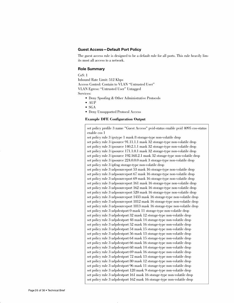
Guest Access—Default Port Policy
The guest access rule is designed to be a default rule for all ports. This rule heavily lim-its most all access to a network.
Role Summary
CoS: 1Inbound Rate Limit: 512 KbpsAccess Control: Contain to VLAN “Untrusted User”VLAN Egress: “Untrusted User” UntaggedS e r v i c e s :
• Deny Spoofing & Other Administrative Protocols• A U P• S G A• Deny Unsupported Protocol Access
Example DFE Configuration Output
set policy profile 3 name "Guest Access" pvid-status enable pvid 4095 cos-statusenable cos 1 set policy rule 3 ipxtype 1 mask 8 storage-type non-volatile dropset policy rule 3 ipsource 91.11.1.1 mask 32 storage-type non-volatile dropset policy rule 3 ipsource 140.2.1.1 mask 32 storage-type non-volatile dropset policy rule 3 ipsource 171.1.0.1 mask 32 storage-type non-volatile dropset policy rule 3 ipsource 192.168.2.1 mask 32 storage-type non-volatile dropset policy rule 3 ipsource 224.0.0.0 mask 3 storage-type non-volatile dropset policy rule 3 ipfrag storage-type non-volatile dropset policy rule 3 udpsourceport 53 mask 16 storage-type non-volatile dropset policy rule 3 udpsourceport 67 mask 16 storage-type non-volatile dropset policy rule 3 udpsourceport 69 mask 16 storage-type non-volatile dropset policy rule 3 udpsourceport 161 mask 16 storage-type non-volatile dropset policy rule 3 udpsourceport 162 mask 16 storage-type non-volatile dropset policy rule 3 udpsourceport 520 mask 16 storage-type non-volatile dropset policy rule 3 udpsourceport 1433 mask 16 storage-type non-volatile dropset policy rule 3 udpsourceport 1812 mask 16 storage-type non-volatile dropset policy rule 3 udpsourceport 1813 mask 16 storage-type non-volatile dropset policy rule 3 udpdestport 0 mask 11 storage-type non-volatile dropset policy rule 3 udpdestport 32 mask 12 storage-type non-volatile dropset policy rule 3 udpdestport 48 mask 14 storage-type non-volatile dropset policy rule 3 udpdestport 52 mask 16 storage-type non-volatile dropset policy rule 3 udpdestport 54 mask 15 storage-type non-volatile dropset policy rule 3 udpdestport 56 mask 13 storage-type non-volatile dropset policy rule 3 udpdestport 64 mask 15 storage-type non-volatile dropset policy rule 3 udpdestport 66 mask 16 storage-type non-volatile dropset policy rule 3 udpdestport 68 mask 14 storage-type non-volatile dropset policy rule 3 udpdestport 69 mask 16 storage-type non-volatile dropset policy rule 3 udpdestport 72 mask 13 storage-type non-volatile dropset policy rule 3 udpdestport 80 mask 12 storage-type non-volatile dropset policy rule 3 udpdestport 96 mask 11 storage-type non-volatile dropset policy rule 3 udpdestport 128 mask 9 storage-type non-volatile dropset policy rule 3 udpdestport 161 mask 16 storage-type non-volatile dropset policy rule 3 udpdestport 162 mask 16 storage-type non-volatile drop
16894_9013963_SecTech_TB 5/9/05 9:30 AM Page 26

Page 2 7 of 36 • Technical Brief
set policy rule 3 udpdestport 256 mask 8 storage-type non-volatile dropset policy rule 3 udpdestport 512 mask 7 storage-type non-volatile dropset policy rule 3 udpdestport 1024 mask 6 storage-type non-volatile dropset policy rule 3 udpdestport 2048 mask 5 storage-type non-volatile dropset policy rule 3 udpdestport 4096 mask 4 storage-type non-volatile dropset policy rule 3 udpdestport 8192 mask 3 storage-type non-volatile dropset policy rule 3 udpdestport 16384 mask 2 storage-type non-volatile dropset policy rule 3 udpdestport 32768 mask 1 storage-type non-volatile dropset policy rule 3 tcpsourceport 20 mask 16 storage-type non-volatile dropset policy rule 3 tcpsourceport 21 mask 16 storage-type non-volatile dropset policy rule 3 tcpsourceport 22 mask 16 storage-type non-volatile dropset policy rule 3 tcpsourceport 23 mask 16 storage-type non-volatile dropset policy rule 3 tcpsourceport 25 mask 16 storage-type non-volatile dropset policy rule 3 tcpsourceport 53 mask 16 storage-type non-volatile dropset policy rule 3 tcpsourceport 80 mask 16 storage-type non-volatile dropset policy rule 3 tcpsourceport 443 mask 16 storage-type non-volatile dropset policy rule 3 tcpsourceport 1433 mask 16 storage-type non-volatile dropset policy rule 3 tcpsourceport 1908 mask 16 storage-type non-volatile dropset policy rule 3 tcpsourceport 6346 mask 16 storage-type non-volatile dropset policy rule 3 tcpdestport 0 mask 10 storage-type non-volatile dropset policy rule 3 tcpdestport 22 mask 16 storage-type non-volatile dropset policy rule 3 tcpdestport 23 mask 16 storage-type non-volatile dropset policy rule 3 tcpdestport 64 mask 12 storage-type non-volatile dropset policy rule 3 tcpdestport 81 mask 16 storage-type non-volatile dropset policy rule 3 tcpdestport 82 mask 15 storage-type non-volatile dropset policy rule 3 tcpdestport 84 mask 14 storage-type non-volatile dropset policy rule 3 tcpdestport 88 mask 13 storage-type non-volatile dropset policy rule 3 tcpdestport 96 mask 11 storage-type non-volatile dropset policy rule 3 tcpdestport 128 mask 9 storage-type non-volatile dropset policy rule 3 tcpdestport 256 mask 9 storage-type non-volatile dropset policy rule 3 tcpdestport 384 mask 11 storage-type non-volatile dropset policy rule 3 tcpdestport 416 mask 12 storage-type non-volatile dropset policy rule 3 tcpdestport 432 mask 13 storage-type non-volatile dropset policy rule 3 tcpdestport 440 mask 15 storage-type non-volatile dropset policy rule 3 tcpdestport 442 mask 16 storage-type non-volatile dropset policy rule 3 tcpdestport 444 mask 14 storage-type non-volatile dropset policy rule 3 tcpdestport 448 mask 10 storage-type non-volatile dropset policy rule 3 tcpdestport 512 mask 7 storage-type non-volatile dropset policy rule 3 tcpdestport 1024 mask 7 storage-type non-volatile dropset policy rule 3 tcpdestport 1536 mask 9 storage-type non-volatile dropset policy rule 3 tcpdestport 1664 mask 11 storage-type non-volatile dropset policy rule 3 tcpdestport 1696 mask 12 storage-type non-volatile dropset policy rule 3 tcpdestport 1712 mask 13 storage-type non-volatile dropset policy rule 3 tcpdestport 1720 mask 15 storage-type non-volatile dropset policy rule 3 tcpdestport 1720 mask 16 storage-type non-volatile forward cos 1set policy rule 3 tcpdestport 1722 mask 16 storage-type non-volatile dropset policy rule 3 tcpdestport 1724 mask 14 storage-type non-volatile dropset policy rule 3 tcpdestport 1728 mask 10 storage-type non-volatile dropset policy rule 3 tcpdestport 1792 mask 8 storage-type non-volatile dropset policy rule 3 tcpdestport 2048 mask 5 storage-type non-volatile dropset policy rule 3 tcpdestport 4096 mask 4 storage-type non-volatile drop
16894_9013963_SecTech_TB 5/9/05 9:30 AM Page 27
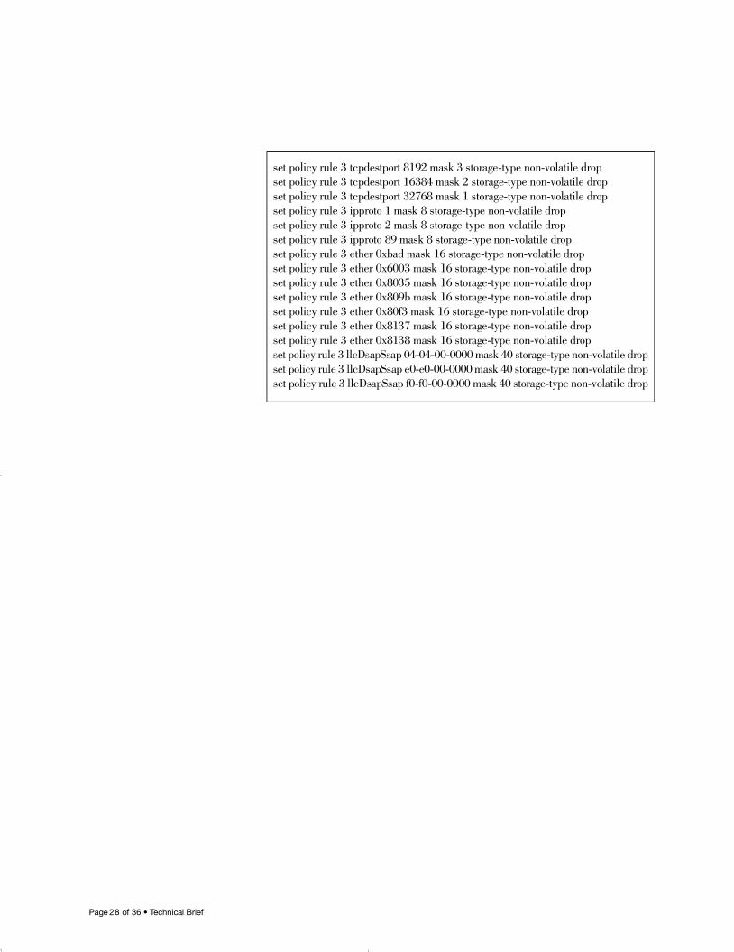
Page 2 8 of 36 • Technical Brief
set policy rule 3 tcpdestport 8192 mask 3 storage-type non-volatile dropset policy rule 3 tcpdestport 16384 mask 2 storage-type non-volatile dropset policy rule 3 tcpdestport 32768 mask 1 storage-type non-volatile dropset policy rule 3 ipproto 1 mask 8 storage-type non-volatile dropset policy rule 3 ipproto 2 mask 8 storage-type non-volatile dropset policy rule 3 ipproto 89 mask 8 storage-type non-volatile dropset policy rule 3 ether 0xbad mask 16 storage-type non-volatile dropset policy rule 3 ether 0x6003 mask 16 storage-type non-volatile dropset policy rule 3 ether 0x8035 mask 16 storage-type non-volatile dropset policy rule 3 ether 0x809b mask 16 storage-type non-volatile dropset policy rule 3 ether 0x80f3 mask 16 storage-type non-volatile dropset policy rule 3 ether 0x8137 mask 16 storage-type non-volatile dropset policy rule 3 ether 0x8138 mask 16 storage-type non-volatile dropset policy rule 3 llcDsapSsap 04-04-00-0000 mask 40 storage-type non-volatile dropset policy rule 3 llcDsapSsap e0-e0-00-0000 mask 40 storage-type non-volatile dropset policy rule 3 llcDsapSsap f0-f0-00-0000 mask 40 storage-type non-volatile drop
16894_9013963_SecTech_TB 5/9/05 9:30 AM Page 28
Page 2 9 of 36 • Technical Brief
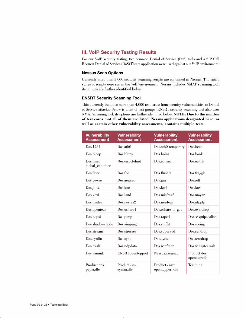
III. VoIP Security Testing ResultsFor our VoIP security testing, two common Denial of Service (DoS) tools and a SIP CallRequest Denial of Service (DoS) Threat application were used against our VoIP environment.
Nessus Scan Options
Currently more than 3,000 security scanning scripts are contained in Nessus. The entiresuites of scripts were run in the VoIP environment. Nessus includes NMAP scanning tool;its options are further identified below.
ENSRT Security Scanning Tool
This currently includes more than 4,000 test cases from security vulnerabilities to Denialof Service attacks. Below is a list of test groups. ENSRT security scanning tool also usesNMAP scanning tool; its options are further identified below. NOTE: Due to the numberof test cases, not all of them are listed. Nessus applications designated here, aswell as certain other vulnerability assessments, contains multiple tests.
Vulnerability Vulnerability Vulnerability VulnerabilityAssessment Assessment Assessment Assessment
D o s . 1 2 3 4 D o s . a t h 0 D o s . a t h 0 - t e m p o r a r y D o s . b e e r
D o s . b l o o p D o s . b l u r p D o s . b o i n k D o s . b o n k
D o s . c i s c o _ D o s . c i s c o t e l n e t D o s . c o n s e a l D o s . e c h o kg l o b a l _ e x p l o i t e r
D o s . f a w x D o s . f b o D o s . f l u s h o t D o s . f r a g g l e
D o s . g e w s e D o s . g e w s e 5 D o s . g i n D o s . j o l t
D o s . j o l t 2 D o s . k o c D o s . k o d D o s . k o x
D o s . k o x i D o s . l a n d D o s . m i s f r a g 2 D o s . m o y a r i
D o s . n e s t e a D o s . n e s t e a 2 D o s . n e w t e a r D o s . n t p p t p
D o s . o p e n t e a r D o s . o s h a r e 1 D o s . o s h a r e _ 1 _ g o u D o s . o v e r d r o p
D o s . p e p s i D o s . p i m p D o s . r a p e d D o s . s e s q u i p e d a l i a n
D o s . s h a d o w c h o d e D o s . s i m p i n g D o s . s p i f f i t D o s . s p r i n g
D o s . s t r e a m D o s . s t r e s s e r D o s . s u p e r k o d D o s . s y n d r o p
D o s . s y n f i n D o s . s y n k D o s . s y n s o l D o s . t e a r d r o p
D o s . t r a s h D o s . u d p d a t a D o s . w i n f r e e z D o s . w i n g a t e c r a s h
D o s . w i n n u k E N S RT. o p e n t c p p o r t N e s s u s . x s c a n a l l P r o d u c t . d o s .o p e n t e a r. d f e
P r o d u c t . d o s . P r o d u c t . d o s . P r o d u c t . e n s r t . Te s t . p i n gp e p s i . d f e s y n f i n . d f e o p e n t c p p o r t . d f e
16894_9013963_SecTech_TB 5/9/05 9:30 AM Page 29
Page 3 0 of 36 • Technical Brief
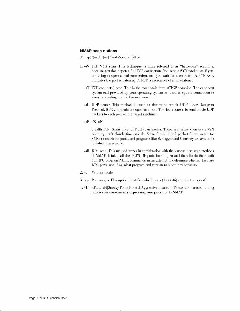
NMAP scan options
(Nmap) 1(–sU) 2(–v) 3(–p1-65535) 4( – T 5 )
1 . - s S TCP SYN scan: This technique is often referred to as “half-open” scanning, because you don’t open a full TCP connection. You send a SYN packet, as if you are going to open a real connection, and you wait for a response. A SYN|ACK indicates the port is listening. A RST is indicative of a non-listener.
- s T TCP connects() scan: This is the most basic form of TCP scanning. The connect()system call provided by your operating system is used to open a connection to every interesting port on the machine.
- s U UDP scans: This method is used to determine which UDP (User Datagram Protocol, RFC 768) ports are open on a host. The technique is to send 0 byte UDPpackets to each port on the target machine.
-sF -sX -sN
Stealth FIN, Xmas Tree, or Null scan modes: There are times when even SYN scanning isn’t clandestine enough. Some firewalls and packet filters watch forSYNs to restricted ports, and programs like Synlogger and Courtney are availableto detect these scans.
- s R RPC scan. This method works in combination with the various port scan methods of NMAP. It takes all the TCP/UDP ports found open and then floods them withSunRPC program NULL commands in an attempt to determine whether they areRPC ports, and if so, what program and version number they serve up.
2 . - v Verbose mode
3 . - p Port ranges. This option identifies which ports (1-65535) you want to specify.
4 . - T <Paranoid|Sneaky|Polite|Normal|Aggressive|Insane>. These are canned timing policies for conveniently expressing your priorities to NMAP.
16894_9013963_SecTech_TB 5/9/05 9:30 AM Page 30
Page 3 1 of 36 • Technical Brief
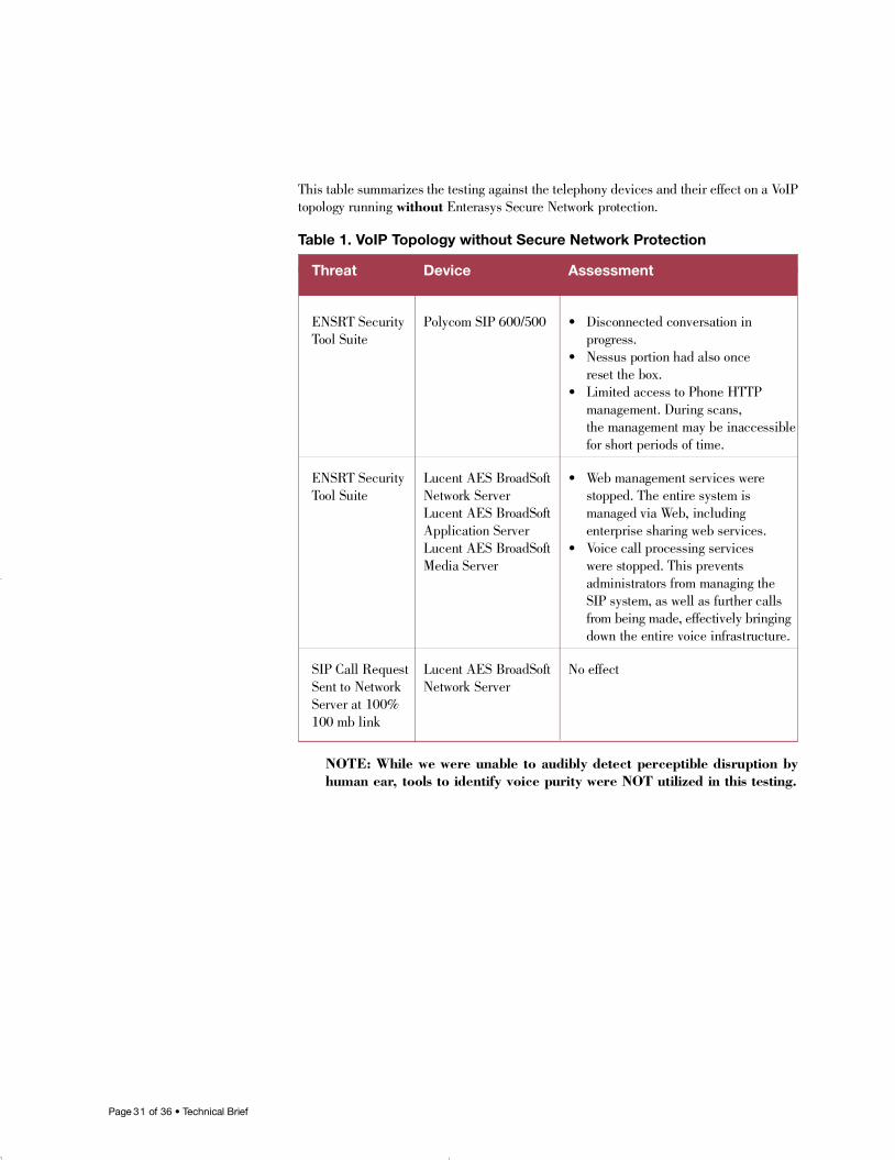
This table summarizes the testing against the telephony devices and their effect on a Vo I Ptopology running w i t h o u t Enterasys Secure Network protection.
Table 1. VoIP Topology without Secure Network Protection
NOTE: While we were unable to audibly detect perceptible disruption byhuman ear, tools to identify voice purity were NOT utilized in this testing.
Threat Device Assessment
E N S RT Security Polycom SIP 600/500 • Disconnected conversation in Tool Suite p r o g r e s s .
• Nessus portion had also once reset the box.
• Limited access to Phone HTTPmanagement. During scans,the management may be inaccessiblefor short periods of time.
E N S RT Security Lucent AES BroadSoft • Web management services were Tool Suite Network Server stopped. The entire system is
Lucent AES BroadSoft managed via Web, including Application Server enterprise sharing web services.Lucent AES BroadSoft • Voice call processing servicesMedia Server were stopped. This prevents
administrators from managing the SIP system, as well as further calls from being made, effectively bringing down the entire voice infrastructure.
SIP Call Request Lucent AES BroadSoft No effectSent to Network Network ServerServer at 100% 100 mb link
16894_9013963_SecTech_TB 5/9/05 9:30 AM Page 31
Page 3 2 of 36 • Technical Brief
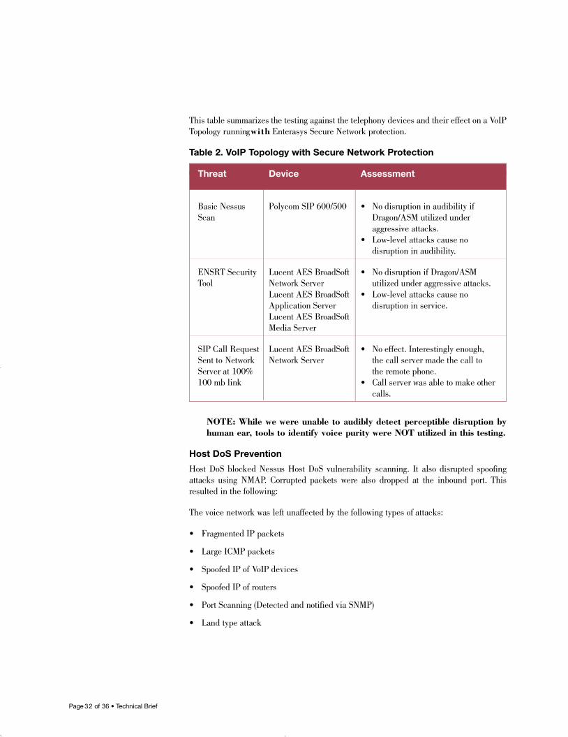
This table summarizes the testing against the telephony devices and their effect on a Vo I PTopology running w i t h Enterasys Secure Network protection.
Table 2. VoIP Topology with Secure Network Protection
NOTE: While we were unable to audibly detect perceptible disruption byhuman ear, tools to identify voice purity were NOT utilized in this testing.
Host DoS Prevention
Host DoS blocked Nessus Host DoS vulnerability scanning. It also disrupted spoofingattacks using NMAP. Corrupted packets were also dropped at the inbound port. Thisresulted in the following:
The voice network was left unaffected by the following types of attacks:
• Fragmented IP packets
• Large ICMP packets
• Spoofed IP of VoIP devices
• Spoofed IP of routers
• Port Scanning (Detected and notified via SNMP)
• Land type attack
Threat Device Assessment
Basic Nessus Polycom SIP 600/500 • No disruption in audibility if S c a n Dragon/ASM utilized under
aggressive attacks.• Low-level attacks cause no
disruption in audibility.
E N S RT Security Lucent AES BroadSoft • No disruption if Dragon/ASM To o l Network Server utilized under aggressive attacks.
Lucent AES BroadSoft • Low-level attacks cause noApplication Server disruption in service.Lucent AES BroadSoft Media Server
SIP Call Request Lucent AES BroadSoft • No effect. Interestingly enough,Sent to Network Network Server the call server made the call toServer at 100% the remote phone.100 mb link • Call server was able to make other
c a l l s .
16894_9013963_SecTech_TB 5/9/05 9:30 AM Page 32
Page 3 3 of 36 • Technical Brief
Access Control Lists
Access control lists were implemented on the voice VLAN to allow only a managementstation connected to the data VLAN communication to Lucent Servers and SIP Phones.Ports 161 and 162 opened for SNMP-based management and traps for devices on the voiceVLAN. All other traffic types were filtered out. Specific source/destination IPs were alsoestablished to prevent other machines from attempting to traverse the voice VLAN. Thisresulted in the following:
Users other than management station are denied access to devices identified on the voiceVLAN. Matrix N7 logging identified ACL actions being taken.
Prevented voice from being chopped up in the event that a hacker streamed UDP or TCP trafficto an end phone. Voice degradation is caused by latency or dropped/out of sequence packets.
802.1x
802.1x is utilized on the data VLAN to provide user-based authentication and policy. Thisauthentication method prevents unauthorized users from gaining unlimited access to thenetwork. This resulted in the following:
Upon user authentication, the filter-id passed through by the RADIUS server causes theswitch to place policy role on the port from which the user is requesting access.
MAC Authentication
MAC authentication is implemented for IP phones on the voice VLAN. When a phone isinserted into a port, it is authenticated via MAC address to the RADIUS Server. Once theRADIUS server passes back successful authentication, the port is applied the appropriatepolicy role for an IP phone. This resulted in the following:
This implementation allows only valid IP phones onto the voice VLAN. Devices that areattempting to simulate IP phones will not be authentication. However, it is feasible for ahacker to spoof MAC and IP address of a phone, which will grant them port access as anIP phone. If a hacker were to gain access under an IP phone policy, they are limited in tospecific communication such as:
• SIP to/from media servers and other IP phones
• Limited to 512 Kbps inbound/outbound. They are unable to saturate an interface or perform high-speed network analysis.
• All other unnecessary ports are disabled to prevent access to unnecessary ports in anattempt to find weaknesses within the network.
Flow Setup Throttling (FST)
General application to prevent attacks that attempt to open multiple flows on an interface.This resulted in the following:
Some applications such as Nessus or NMAP configured to scan large amounts ofUDP/TCP ports or IP ranges will be limited or even disabled from doing so. This studysimply limits the amount of flows that an attacker can initiate, ultimately resulting in twothings:
16894_9013963_SecTech_TB 5/9/05 9:30 AM Page 33
Page 3 4 of 36 • Technical Brief
• Attacker is unable to open an overwhelming number of sessions to any voice, data ornetwork device.
• Attacker port may be disabled if configured. This is a means to identify an obtrusiveinterface on the network, an SNMP alarm is sent to the SNMP management stationidentifying the user port and disabled action.
MAC Locking
MAC locking is configured in the voice VLAN to prevent an attacker from removing aphone and plugging in their own PC or unrelated device. This resulted in the following:
When a port has learned the MAC of the phone that was initially installed on it, it will denycommunication from any other MAC. This does not provide a solution for attackers thatmanipulate the MAC address to match that of the phone. However, it will prevent the“script kiddies” (users that are not proficient in security) from gaining access to the voicen e t w o r k .
Another recommendation is to monitor the link states of phone ports. A phone should notbe causing link up/downs. This could determine that someone has attempted to access thisport for intentions other than phone usage.
Data Provisioning/Class of Service
Data Provisioning and Class of Service is applied to allow network-critical applications tocontinue communicating under times in which a network is stressed. Stress could constituteas a worm or virus spreading, distributed Denial of Service attack, or an attacker sendinghigh rates of specific traffic into a network. Class of Service for voice was given a priorityof high. Other services such as HTTP were given a medium priority. All other traffic isclassified low by default. This resulted in the following:
Voice VLAN is unaffected by broadcast, chatty, or large volumes of traffic that may constitute as a virus/worm spreading. This feature must be configured globally on thedevice. If not, conditions where congestion may be heavy on the DATA LAN, may causedelay in packets on the voice LAN due to backplane bus over subscription.
Firewall
Implementation requires a SIP ALG capable firewall. The media servers can be placedbehind these protected firewall interfaces. The concept of a firewall ALG (ApplicationLayer Gateway) is to inspect the SIP protocol and enforce proper functionality. This resultedin the following:
If an attacker is using attacks that orient around damaging the SIP protocol stack or func-tional specification, the ALG will remove the packets from the line.
NOTE: A firewall was not utilized in the Lucent solution testing. However,utilization of a firewall will provide added security.
VLANs
VLANS are implemented to separate and contain voice and data systems. Even thoughthis may not be a scalable solution for a large mixed network device environment, it doescreate a more secure scenario. This results in the following:
16894_9013963_SecTech_TB 5/9/05 9:30 AM Page 34
Page 3 5 of 36 • Technical Brief
Implementation of separate voice and data VLANS segmented both data and voicedevices. This implementation prevents unnecessary traffic from hitting VoIP devices.Unnecessary traffic could be ARP broadcasts, any Windows OS broadcast type traffic, orany other packets that may be sent out to all ports.
Secure Host VLAN
The switch’s management interface is only be accessible by administrators, network man-agement stations, and servers. Users on the network (secure guest or authenticated enter-prise users) do not have the ability to contact the host. By isolating the host from users thechances of an attacker modifying a configuration file or compromising the host via a Denialof Service (DoS) attack are reduced.
Stream Call Requests
This is a form of Denial of Service (DoS) attack against a gateway or gatekeeper. Thethought behind this attack is to keep the gateway/gatekeeper busy so that it can’t attend tonormal call activity on the network. Utilizing Secure Networks policies the followingresults were obtained:
Rate limiting protected the Media Servers from receiving an overwhelming number of callrequests.
SSH
SSH encrypts all traffic (including passwords) to effectively eliminate eavesdropping, connection hijacking, and other network-level attacks.
SNMPv3
SNMPv3 was used on all devices with authentication and privacy passwords enabled. Alluser ports explicitly discarded SNMP via policy.
RADIUS
Only switch hosts should be allowed to contact the RADIUS server; all others will beexplicitly denied access via policy and ACL deployment.
Inbound Rate Limiting/Class of Service
Inbound rate limiting is implemented on port roles for VoIP phones. When a phone isinserted into a port, the device is authenticated via MAC authentication and then provideda policy role that limits port traffic to 64 Kbps inbound and outbound. This value needs tobe adjusted based on vendor voice compression implementation. This resulted in the f o l l o w i n g :
Voice inaudibility was prevented in the event that a hacker streamed UDP or TCP trafficto an end phone. Voice degradation is caused by latency or dropped/out-of-sequence packets.
Outbound Rate Limiting/Class of Service
Outbound rate limiting is implemented on port roles for VoIP phones. When a phone isinserted into a port, the device is authenticated via MAC authentication and then provideda policy role that limits port traffic to 64 Kbps inbound and outbound. This value needs tobe adjusted based on vendor voice compression implementation. This resulted in the following:
Voice inaudibility was prevented in the event that a hacker streamed UDP or TCP trafficto an end phone. Voice degradation is caused by latency or dropped/out of sequence packets.
16894_9013963_SecTech_TB 5/9/05 9:30 AM Page 35
All contents are copyright © 2005 EnterasysNetworks, Inc. All rights re s e r v e d .
Lit. #9013963 5/05
Page 3 6 of 36 • Technical Brief
Spanguard
Reception of a BPDU by a port caused the port to be locked and its state set to blocking.The port was locked for a globally specified time, which may be forever if the timer valueis set to 0.
Broadcast Suppression
Broadcast Suppression limited the number of received broadcast frames.
Logging
SYSLOG messages were sent to a centralized server.
Acceptable Use Policy (AUP)
Acceptable Use Policy (AUP) is set of rules that are configured for all users logging intothe network via 8021.x authentication. This results in the following:
Allows access to necessary resources for day-to-day business activities. This rule preventsusers from communicating on ports that are unnecessary such as HTTP Server, TFTP,S N M P, DNS Imposter, Bootp, RIP, IPX, AppleTalk, IGMP, Reverse ARP, etc.
Dynamic Intrusion Response
Dynamic Intrusion Response (DIR) is implemented on the interfaces in front of the firewallto further protect the gatekeepers and gateways from malicious attacks. This resulted inthe following:
When DIR detects malicious activity on a network, it will search out the offending sourceport and take action. In this test case, we took the extreme action and disabled the port.Network administrators may implement DIR to query for manual disruption of offendingsource port. Although it is important to maintain 99.999 uptime for a voice system, imme-diate disabling of the port and notification to administration should be a considerationwhere phone services are absolute critical.
Testing Comments
1. SIP-specific security vulnerabilities need to be expanded outside of Nessus plug-ins for future testing.
2. Dragon and ASM prevention system is key for aggressive attack scenarios.
IV. ConclusionUnderstanding not only the proprietary mechanisms of voice technology but also the pro-tocol technologies themselves can be a challenge. Secure convergence technologies suchas voice, which lack security enhancements, rely heavily on a network to protect theirf u n c t i o n a l i t y. Designing best-of-class security solutions through Secure Networks is thefoundation for these designs, but requires additional fine tuning.
In summary, the Secure Networks components deployed in this testing ensured the integrityand quality of VoIP in the network infrastructure, while maintaining a hardened securityposture for all network resources.
16894_9013963_SecTech_TB 5/9/05 9:30 AM Page 36


![[PPT]RTMM, VoIP, VVoIP, NGN? - Rhodes · Web viewRTMM, VoIP, VVoIP, NGN, Convergence? Alfredo Terzoli / Mosioua Tsietsi PLAN Admin Real time communication today: your experience A](https://img.dokumen.tips/doc/110x75/5aa1f8287f8b9a1f6d8c9bee/pptrtmm-voip-vvoip-ngn-rhodes-viewrtmm-voip-vvoip-ngn-convergence-alfredo.jpg)