Embed Size (px)
Citation preview

VOICE COMMUNICATIONSINTERCOM SYSTEMS
SYSTEM APPLICATIONS
CHURCHSCHOOLTHEATERSTUDIOINDUSTRIALMILITARY
For more information, please contact:Telex Communications, Inc.12000 Portland Avenue South
Burnsville, MN 55337
Tel: (800) 392-3497 Fax: (800) 392-0498

PROPRIETARY NOTICE
The RTS product information and design disclosed herein were originated by and are the property ofTelex Communications, Inc. Telex reserves all patent, proprietary design, manufacturing, reproduc-tion, use and sales rights thereto, and to any article disclosed therein, except to the extent rights areexpressly granted to others.
COPYRIGHT NOTICE
Copyright 2003 by Telex Communications, Inc. All rights reserved. Reproduction in whole or in partwithout prior written permission from Telex is prohibited.
CUSTOMER SUPPORTTechnical questions should be directed to:
Customer Service DepartmentRTS/Telex,12000 Portland Avenue SouthBurnsville, MN 55337 U.S.A.Telephone: (800) 392-3497Fax: (800) 323-0498

Table of Contents
Audiocom One Channel System .....................................................................................................4
Two Channel System with SingleChannel Beltpacks ..........................................................................................................................6
Two Channel System with TwoChannel Beltpacks ..........................................................................................................................8
Audiocom Small Church - 2 Channel ..............................................................................................10
Audiocom Two Channel ProductionSystem ............................................................................................................................................ 12
Audiocom Two Channel Mixed System ...........................................................................................14
Audiocom Two Channel Conference System ..................................................................................17
Audiocom Cath Lab System AND AudiocomCath Lab 2 Systems ........................................................................................................................19
Audiocom Small Fiber AND Large Fiber System ............................................................................22
Audiocom Large 6 Channel Master Station System ........................................................................26
Audiocom 6 Channel IC-6SX System UsingSource Assignment Panels ............................................................................................................. 28
6 Channel Master Station for Church ...............................................................................................30
Audiocom 10-Channel User Station System ...................................................................................33
RadioCom Single Channel Systems700 Series UHF and 300 Series VHF Wireless Intercom ...........................................................35
RadioCom Two Channel Systems800 Series UHF Wireless Intercom ............................................................................................ 38500 Series UHF and 600 Series Encrypted UHF Wireless Intercom .........................................41
Zeus / Audiocom Combo Intercom System ......................................................................................44
Cable Drawings...............................................................................................................................47
Audiocom One Channel System
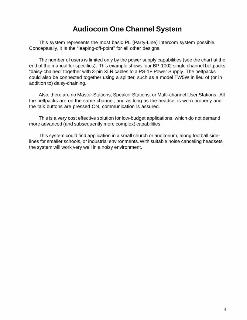
This system represents the most basic PL (Party-Line) intercom system possible.Conceptually, it is the “leaping-off-point” for all other designs.
The number of users is limited only by the power supply capabilities (see the chart at theend of the manual for specifics). This example shows four BP-1002 single channel beltpacks“daisy-chained” together with 3-pin XLR cables to a PS-1F Power Supply. The beltpackscould also be connected together using a splitter, such as a model TW5W in lieu of (or inaddition to) daisy-chaining.
Also, there are no Master Stations, Speaker Stations, or Multi-channel User Stations. Allthe beltpacks are on the same channel; and as long as the headset is worn properly andthe talk buttons are pressed ON, communication is assured.
This is a very cost effective solution for low-budget applications, which do not demandmore advanced (and subsequently more complex) capabilities.
This system could find application in a small church or auditorium, along football side-lines for smaller schools, or industrial environments. With suitable noise canceling headsets,the system will work very well in a noisy environment.
4

Two-Channel System with Single Channel Beltpacks
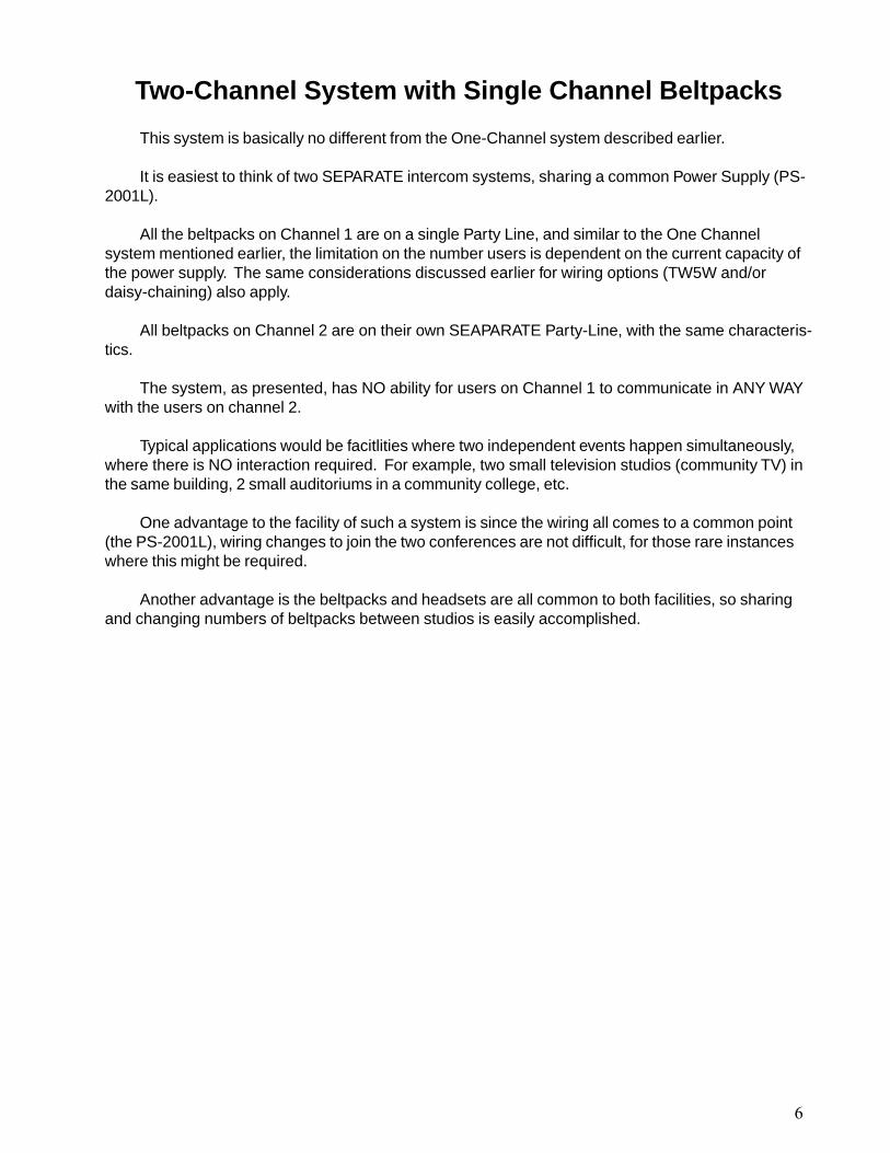
This system is basically no different from the One-Channel system described earlier.
It is easiest to think of two SEPARATE intercom systems, sharing a common Power Supply (PS-2001L).
All the beltpacks on Channel 1 are on a single Party Line, and similar to the One Channelsystem mentioned earlier, the limitation on the number users is dependent on the current capacity ofthe power supply. The same considerations discussed earlier for wiring options (TW5W and/ordaisy-chaining) also apply.
All beltpacks on Channel 2 are on their own SEAPARATE Party-Line, with the same characteris-tics.
The system, as presented, has NO ability for users on Channel 1 to communicate in ANY WAYwith the users on channel 2.
Typical applications would be facitlities where two independent events happen simultaneously,where there is NO interaction required. For example, two small television studios (community TV) inthe same building, 2 small auditoriums in a community college, etc.
One advantage to the facility of such a system is since the wiring all comes to a common point(the PS-2001L), wiring changes to join the two conferences are not difficult, for those rare instanceswhere this might be required.
Another advantage is the beltpacks and headsets are all common to both facilities, so sharingand changing numbers of beltpacks between studios is easily accomplished.
6

Two Channel System with Two Channel Belt Packs
This system is designed to allow all beltpacks to CHOOSE between EITHER of twochannels.
Like the previous examples, there is no Master Station. No station has the ability to simultaneouslyspeak or listen to BOTH channels.
The differences between this and the two previous systems are substantial in a couple of re-spects. Communications are LESS assured. For example, if a user on Channel one wishes to speak toanother user, it is possible the second user is not wearing a headset or the second user is on a differentchannel and will not hear the first user.
The BP-1002 beltpacks provide each user the opportunity to select which channel of communica-tion they wish to participate on.
Another difference is the cabling. The first two systems use standard XLR-3 cable, where thissystem requires the use of less common XLR-6 cables between beltpacks. The Junction Block shown(JB-2) converts the two single channel XLR-3 connections from the PS-2001L into a single XLR-6connector. 6-pin daisy chain cables and splitters are now required.
In some applications, it may be better to have CERTAIN users fixed to one channel or another byconnecting BP-1002 single channel beltpacks directly to the XLR connections prior to the JB-2 for therequired channel. Examples of this will be seen in the next systems.
It is easiest to think of these beltpacks as two SEPARATE intercom systems sharing a commonPower Supply (PS-2001L).
All the beltpacks on Channel 1 are on a single Party-Line, and like the one channel system, pre-sented earlier, the limitation on the number of users is dependent on the current capacity of the powersupply. The same considerations discussed earlier for wiring options (TW5W and/or daisy-chaining)also apply.
All the beltpacks on Channel 2 are likewise on their own SEPARATE Party-Line with the samecharacteristics.
The system, as presented, has NO ability for users on Channel 1 to communicate in ANY WAY withthe users on Channel 2.
Typical applications would be facilities where two independent events happen simultaneously, wherethere is NO interaction required. For example, two small television studios (community TV) in the samebuilding, to small auditoriums in a community college, etc.
One advantage to the facility of such a system is the wiring all comes to a common point (the PS-2001L), wiring changes to join the two conferences are not difficult, for those rare instances where thismay be required.
Another advantage is the beltpacks and headsets are all common to both facilites, so sharingequipment and changing numbers of beltpacks between studios is easily accomplished.
8


Audiocom Small Church - 2 Channel
First of all, “Audiocom” is misleading, as this system also has Radiocom Wireless Inter-com equipment. “Church” may also be misleading, as it is but one of hundreds of possiblevenues for such a system.
This system differs from the earlier systems in a number of ways:
First, it has a mixture of BP-1002 and BP-2002 1 and 2-channel beltpacks, along with asingle channel. This allows some users to be permanently assigned to a single channelfor the sake of simplicity, while allowing a “power user” to choose between either of twochannels.
Second, the system has a wireless component in the form of the BTR-300 system, whichprovides (as shown) 4 wireless beltpacks (can be bought with 1, 2, 3, or 4 beltpacks perbase). These wireless beltpacks give those users great freedom of movement (typicallymore than 100 yards).
Note, in this example, the wireless beltpacks (TR-300 units) are on channel 2, while theBP-1002 beltpacks are on channel 1. There is NO communication possible between thegroup of TR-300 beltpacks and the group of BP-1002 beltpacks. The only user that canCHOOSE which group to talk to is the person on the BP-2002.
The typical application for a system of this type is where the BP-2002 2 channel stationis typically working with ONE of two independent groups or activities which have differentrequirements and are likely NOT happening simultaneously. An example of this setup maybe seen in an auditorium where the BP-1002 units are used during stage-based perfor-mances of plays, while the wireless beltpacks are used during musical performances wherethe performers move around.
10


Audiocom Two Channel Production System
This system represents the first in this group that is specifically designed for and ca-pable of supporting a single event where certain users need to regularly speak with twoseparate conferences (party lines) either separately or simultaneously.
This system also provides IFB (Interrupted Fold Back) feeds to talent. IFB is used todescribe the method by which a director communicates with on-air talent during a program.When you see the reporter in the studio with an unobtrusive earpiece, that earpiece is doing“double duty”. Normally, the talent is hearing the same program that you, the viewer, hearat home...a “fold back” of the studio signal. At times, the director needs to communicatewith the talent to tell them “You have ten seconds, wrap it up NOW”. The director doesthat by interrupting the normal fold back signal, hence the term “Interrupted Fold Back”.This is a one-way communication where the talent is “listen only” which is a capabilityprovided by the IFB-1000 beltpacks.
In the example shown, each of four different reporters has their own channel of IFB, sothe director may choose to speak to any, all or a combination of the reporters at any time.The EMS-4001 Expansion Master Station provides this functionality.
Another part of the system is a fairly conventional 2-channel system, as describedearlier, consisting of the BP-1002 beltpacks. New to this diagram is the inclusion of the WP-3wall plates, which allow the individual beltpacks to plug in where convenient, without con-cerns about daisy-chaining connections. A typical production facility may have manymore WP-3 “drops” than they have corresponding beltpacks, just as a house is likely hasmany unused AC outlets.
Three units are introduced in this diagram:
US-2002: The US-2002 User Station allows the operator to talk and/or listen to eitheror both of the two channels at any time. It overcomes the limitations of a 2-channelbeltpack (such as the BP-2002) which allows the user to talk and/or listen to ONLY one oftwo channels at any time.
MS-2002: The MS-2002 Master Station provides the functionality of a 2-channel powersupply (same as the PS-2001L, described earlier), along with the functionality of a 2-channeluser station, which allows the director to (among other functions) speak to either channel 1,channel 2 or both.
EMS-4001: The EMS-4001 Expansion Master Station provides an additional four chan-nels of power and a four channel user station in one package, so by combining the MS-2002and the EMS-4001 in one location. By doing this, the director will have a 6-channel masterstation with complete access to any or all six channels at any time with separate abilities tolisten and or talk to any/all channels.
12


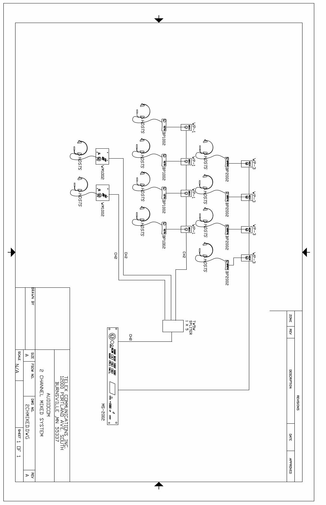
Audiocom Two Channel Mixed System
This system introduces two new concepts and capabilities from the previous examples.
A Master Station (MS-2002) has been added, which combines three functions in oneconvenient package. The MS-2002 combines a 2-channel power supply (same as the PS-2001L), a 2-channel user station capable of simultaneous talk/listen on either or both chan-nels, and a built-in speaker.
In this example, the two available channels are routed to three different types of users.At the top of the diagram, the two channels are both fed through WP-3 wall plates to BP-2002beltpacks, giving users access to either channel.
The channel 2 signal from the MS-2002 is fed to a TW5W splitter which makes thesignal available to five different paths, three of which are used in this example.
Path 1 goes to four wall plates, WP-1 where they connect directly to BP-1002 single-channel beltpacks. As the diagram shows, the daisy chaining for these beltpacks is handledby the permanent wiring “behind” the wall plates. This method allows any beltpack to beconnected or disconnected WITHOUT breaking the chain.
Path 2 goes directly to the WM-1002 wall mount station with headset.
Path 3 goes directly to a WM-1002 wall mount station.
From an operational view, the following communications are possible.
For events where the Master Station is not manned, the BP-1002 and WM-1002 stationswill always be in contact with each other - they can be used for independent operation. TheBP-2002 units can choose to operate on channel 2, where they would then be an integralpart of the BP-1002 and WM-1002 conference for a larger event. If the BP-2002 beltpacksneeded to communicate separately among themselves, either for a moment or an entireevent, they would simply switch to channel 1(but for that time, they would be out of contactwith the BP-1002 and WM-1002 stations which are restricted to channel 2 only).
By adding the User Station portion of the MS-2002 to the mix by manning it, there is nowa great deal of coordination which can occur. For starters, the operator at the MS-2002 cancommunicate with any of the other stations, independently or simultaneously. Unlike the BP-2002 units, the MS-2002 does not need to CHOOSE between the two channels, it can alsochoose BOTH either for talk or listen. The operator may choose to listen to BOTH channels,even while talking with only one of the channels. In that case, (presuming the BP-2002 unitshave selected channel 1) the operator could be working on channel 1 with the BP-2002,and still hear a request from the channel 2 BP-2002s and WM-1002 or even relay a re-quest for one (or more) of the BP-2002 beltpacks to switch to channel 2 to work with theBP-1002 and WM-1002 units. So, we now have a system that can be operated as twostandalone systems, as one large system or as a semi-related system with intercommuni-cations possible between systems.
14

This type of system would be a good basis for a multi-purpose facility, such as found in acommunity TV facility with two smaller studios, that can function as one, or at a conven-tion center with divisible conference areas.
15
Audiocom 2 Channel Conference System
This system, unlike the previous systems, can be said to “put all power in the hands of the people”.In it, each station has the full ability to choose to talk or listen to any channel at any time in any combi-nation.
To quote a line from the 2002 movie, Spider-Man, “With great power. comes great responsibility”.Each user must take the appropriate action to listen to the appropriate channel for the task they areengaged in.
To start at the beginning, a SPS-2001 provides both power and loudspeaker for “headset free”monitoring. In practical applications, it would be located next to one of the US-2002 units. In this setup,you can see the flexibility of the Audiocom modular approach. Mounting a SPS-2001 next to a US-2002results in a unit functionally equivalent to a MS-2002. “Why then”, you say, “not simply install a MS-2002?”. The answer is that the initial installation may have been made without a speaker, and themodular design allows one to be added later without discarding the existing US-2002 or playing foradditional functionality that is not required.
So, we have three identical user stations, with headsets, which can each assign themselves toeither or both of two separate channels of activity - in a small theater, these would be at the lightingboard, sound board, and stage manager locations, where they could participate in sound and/or lightingcues.
The fourth station (with the SPS-2001) has the added ability to operate with heaset or hands-freewith the speaker in the SPS-2001 and an optional gooseneck microphone. This station might reside inthe sound booth, where the operator cannot wear a headset and do their job of running sound.
17


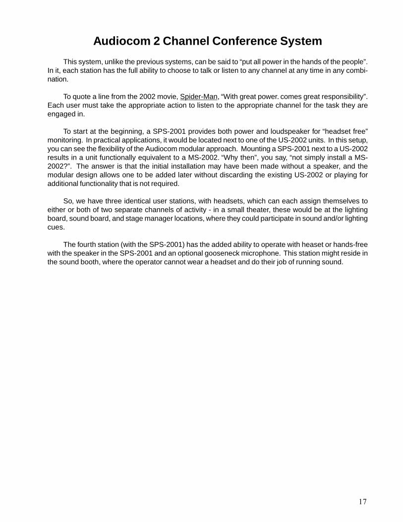
Audiocom Cath Lab System AND AudiocomCath Lab 2 Systems
The two diagrams that follow show variations on the same theme. The differences highlight howEASILY Audiocom intercoms, with their extensive external connections and balanced audio capabil-ity, permit easy interfacing to convention professional audio products such as high quality speakersand microphones.
In a Cath Lab, there is a requirement for the people in the lab to be able to have total hands-freecommunication outside the room. In this case, they must have that communications capabilitythroughout a small room.
This is accomplished by using a ceiling speaker centrally located, fed from the US-2002. Theceiling speaker may or may not require an external amplifier, depending on the volume that is re-quired.
Hands-free speaking in the Cath Lab is accomplished using an external microphone positionedto be as close as possible to the intended operating area for the person speaking.
Attention will have to be paid to sidetone adjustment for this type of installation to maximizelistening volume while minimizing feedback. Conventional professional audio attention to location andpatterns of the speaker and mic are essential.
External to the Lab is the second US-2002, along with a separate PS-2001L. In this case, it isvery likely that separate units are desired, so that the user station is as small and unobtrusive aspossible, by locating the power supply in an out of the way location. Certainly an MS-2002 couldwork just as well, if size and location are not an issue. Typically, this external user station would use aheadset to minimize feedback issues caused by audio coupling from causing feedback in the Lab.
19


Audiocom Small Fiber AND Large Fiber System
The following refers to both Small and Large Systems.
By now, you’ve seen all sorts of variations of Audicom systems, all of which have reliedon the TW or Party-Line concept. In all of these cases, if you were to examine the wiringbetween the units (for single channel), you would find a single balanced audio pair carriesboth sides of the conversation, talk and listen. The two signals are mixed together.
At any intercom station, the audio starts out as DISCRETE TALK and DISCRETE LIS-TEN. The “talk” comes into the intercom station from your mouth (a discrete source), into amicrophone (another discrete source), and then listen audio comes out of the intercom sta-tion via a speaker or earpiece in a headset (another discrete source) into the ears of thelistener.
Once inside the intercom system, however, “the egg gets scrambled” - talk from anintercom station gets impressed onto the same pair of wires that other intercom station “talks”have been impressed upon, so that on the pair of wires are signals that contain (from thepoint of view of any INDIVIDUAL user) both talk and listen.
At any individual intercom station, since we have access to the locally generated “talk”signal, we can “invert and mix” or null the local talk signal “out” of the combined talk andlisten, thus controlling how much of our OWN voice we hear (sidetone adjust).
But, at any other point where we “tap into” the intercom line, it becomes much more of achallenge to “unscramble the egg”. For example, if we want to connect to external deviceswhere we can have separate talk and listen signals a special device is required - a “hybrid”-or in Telex intercom speak, a “System to System Adapter”, such as the SSA-324 or SSA-424.
The SSA units connect to a TW or Party-Line intercom line (“yes, even those made byother companies, such as ClearCom”) and allow external audio to be taken from the intercom(listen) and presented to the intercom (talk). This is not as simple as it sounds, becauseunlike a closed system, the phase relationships, echoes, etc. may vary and make simplenulling very difficult.
Why would we want to separate the talk and listen from a TW intercom system? Wewant to separate the talk and listen from a TW intercom system when we need to connect toa system which is NOT an intercom that cannot function with combined bi-directional talk andlisten signals. A good example of this is a fiber optic cable. Typically, MOST fiber opticcables transmit signals in only one direction.
Say you have two intercom systems a mile apart connected with fiber optic cable (a verycommon occurrence on campuses), any you want to interconnect them. Consider what musthappen: the talk from system 1 (the combination of all its locally generated conversations)must be presented to the fiber optic interface equipment to be sent to the remote intercomsystem. The remote system also must have its talk signal sent BACK to the first intercom
22
system. At each end, the local signal and the remote signal are combined, so that each userat either location can hear the complete conversation, locally and remotely. But, the mergedlocal and remote talk signals are now “scrambled” together, so when the combined signal issent back from either location, the original signal is included, and FEEDBACK!!!! happens.
The job of the SSA “hybrid” is to remove the remote signal as much as possible beforesending it back down the line, which reduces the potential for feedback when two systemsare tied together.
The effectiveness of the hybrid in separating signals is referred to as “nulling”. Telexoffers two different models of SSA units providing different degrees and methods of nulling.
The SSA-324 is a cost effective hybrid (which is analog) and accomplishes its nullingthrough manual adjustment by the user listening to the results and turning the adjustments.The SSA-424 accomplishes its nulling automatically, utilizing DSP, and is more effective, butcomes at a higher cost.
Looking at the Small System diagram, everything to the right of the right-hand SSA, andeverything above and to the left of the left-hand SSA is somewhat immaterial. What is worthnoting is the equipment and technique we would use to get one channel (or more) of oneintercom system across fiber to one channel (or more) of a second intercom system, effec-tively making a single large intercom system.
What you see on the Small System diagram is TWO channels of intercom audio beingsent in each direction (as SSA units are two channels). The fiber interfaces take the twochannels off audio going in one direction, multiplexes them into a single signal, and trans-mits it down one fiber in one direction to the other location. The other end does the same,and each end then receives a signal, and then “de-multiplexes” it back into two discreteintercom channels and sends it on to the SSA to be re-converted into a TW signal, com-bining the talk and listen.
The Large System diagram shows an intercom system using a separate fiber for eachchannel... not because it is required for a large system, but just to show a different means ofacheiving the same goal.
The general principal of using an SSA to connect to a fiber can also be applied in thesame way to interface to ANY uni-directional transmission medium, such as a radio or micro-wave, a corporate data system (LAN) or a dedicated “4-wire circuit”.
23


Audiocom Large 6 Channel Master Station System
This system continues to embody concepts and options shown in earlier systems. At the heart ofthe system is a group of components that make up a six channel master station, in a compact 2 RUfactor.
As discussed earlier, the same configuration could also be built by using a MS-2002 in place of theUS-2002/SPS-2001 combination, and an EMS-4001 in place of the ES-4000/PS-4001.
The net effect is the ability to support six powered channels of intercom with the ability to speak orlisten to any or all from the central master station.
In this example, the top group shows two separate channels of intercom going to two separate“chains” of BP-1002 single channel beltpacks. These appear as channels 1 and 2 on the master sta-tion.
The middle section shows a chain of BP-2002, 2 channel beltpacks connected to channels threeand four of the Master Station.
Warning!!! - The labels on the BP-2002s refer to channel 1 or channel 2 - while in this configura-tion, when the beltpacks select channel 1, they are in reality (from the perspective of the Master Station)selecting channel 3.
The bottom section is similar to the middle section, with the difference that “local channels 1 and2” are “system channels 5 and 6” respectively.
As in earlier systems, these larger, more capable, more flexible systems require greater care andknowledge in administering and operating.
Note the following limitations of this complex system:
The top chain of BP-1002s assigned to channel 1 can ONLY communicate with each other or theMaster Station. The applies to the BP1-1002s assigned to channel 2.
The BP-2002s in the middle can only communicate with other BP-2002s in THEIR OWN CHAIN,which have the same channel (channel 1 or channel 2) selected, or the Master Station.
The bottom chain of BP-2002 have the same limitations and capabilities as the middle group.
26


Audiocom 6 Channel IC-6SX System UsingSource Assignment Panels
All the previous systems, regardless of complexity, have had one thing in common. With smallexceptions, they have been hardwired into a specific configuration, which either enforces or limits thevariety of configurations.
In the real world, needs for intercom systems are rarely so predictable, particularly once webegin looking at systems in facilities which do any variety of functions.
This system shows an IC-6SX Source Assignment Panel.
Very simply, the IC-6SX is a 6 IN by 12 OUT routing switch (albeit a completely passive one) -not much different from a jackfield. With this panel, six channels of intercom from a master station canbe assigned to any of 12 output lines. Those output lines can go to almost any type or group ofintercom stations, from single channel beltpacks to multi-channel user stations.
By the simple action, a person can slide switches on the IC-6SX to different positions andcombine or isolate any intercom stations in any combination.
On one day there may be (as shown in the diagram) six separate groups of beltpacks doing sixseparate tasks on six separate channels. With the simple slide of switches, an operator can re-configure the system into three groups of four, or a group of ten, and a second group of two. Movingbeltpacks from one conference to another becomes very easy.
By placing the IC-6SX physically close to the master station, the central operator can receiveverbal change requests from any of the intercom users, implement those changes, and then confirmverbally what has been done.
The concepts in this drawing can be applied to ANY TW (Party-Line) intercom system to add in adegree of flexibility. The key is to remember the Spiderman quote used earlier, “With great powercomes great responsibility”. Unlike a basic system, in which multiple groups of single channel userstations are permanently assigned to each other, the degree of certainty of who will hear, when aperson picks up a headset and speaks, in a system is MUCH LESS.
28


6 Channel Master Station for Church
This is an actual example of a system installed in a large church.
That is NOT to say it is THE system for large churches, only that it embodies the abilities re-quired for the specific design.
As can be noted from the lables on the drawing “Producer Position”, “Lighting Position”, “VideoPosition”, and the number and assignment of beltpacks, we can deduce the following:
There are three operating positions, as named above.
The Church communications are used primarily in the production of television programming, sothis diagram could be very applicable to a small, function-dedicated television studio in any facility.
The Producer is the “owner” of the 6-channel Master Station and has access to all six channels.He or she can talk and listen to anyone at anytime.
Two channels (channels 1&2) go only to the video position and four beltpacks. The purpose ofthis is to allow the video position to communicate privately with the Producer (for example, on chan-nel 1), while channel 2 also goes to the four beltpacks (like Cameras) with whom the Producer andVideo Position can both communicate.
The Producer also has access to channels 3, 4, 5, and 6 which are routed as follows:
Channel 3 goes to the lighting position, again for private communications between the producerand the lighting position.
Channel 4 goes to the Audio position, also for private communications between the producerand the audio person.
Channel 5 PRIMARILY goes to the lighting position and via a breakout panel also feeds the fourWP-1 wall plates, connceted to four BP-1002 beltpacks, presumably at follow spots, lighting board,and stage manager locations - The lighting position and producer can speak and listen at will to thesebeltpacks. There is also a “cross connect” to the audio position, so the audio operator also hasaccess to this channel.
Channl 6 PRIMARILY goes to the audio position and a single beltpack, presumably at a boommicrophone, or at an audio board. A “cross connect” allows the lighting position to join in; the Pro-ducer (as always) has unfettered access to all positions.
30

In this particular example, the 6 channels are fixed and very closely defined based on to whomand how they are connected.
Channel 1 Private Comms between Producer and VideoChannel 2 Video Party-LineChannel 3 Private Comms between Producer and LightingChannel 4 Private Comms between Producer and AudioChannel 5 Lighting Party-LineChannel 6 Audio Party-Line
This fixed relationship is IDEAL for a facility in which there are NOT resident hi-tech operators.The panels can be permanently labeled as to which channel is which, the confusion is kept to anabsolute minimum and functionality is assured by the hardwired nature of the system.
One final bit of “good design practice” should be noted. The audio and lighting positions haveunused channels present on their keypanels - at ANY point in the future, if desired, additional chan-nels can be added for their exclusive use, or to extend channels 1 and 2 from the video position tothem is a simple matter of wiring. No major equipment additions are required.
31

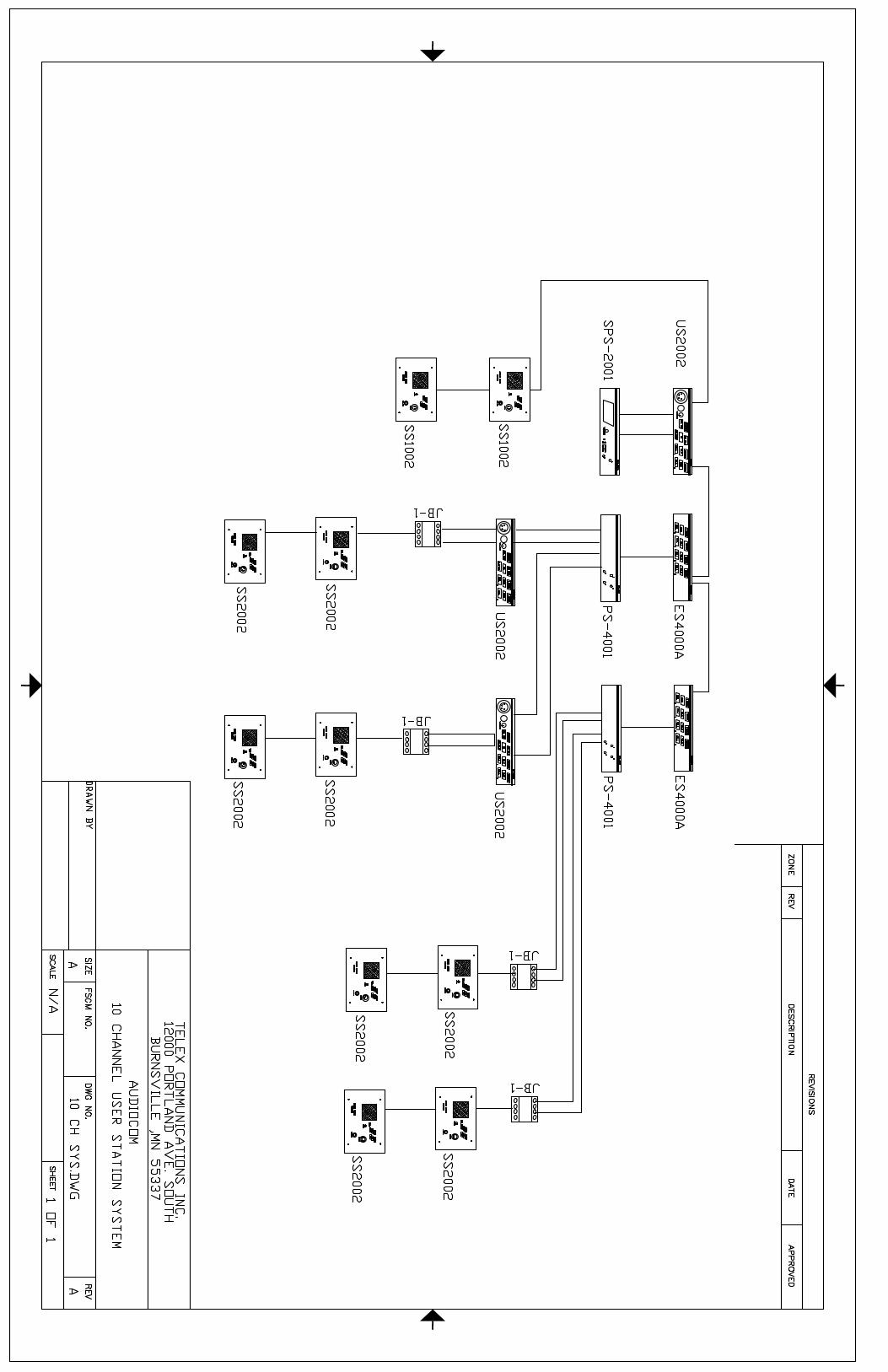
Audiocom 10-Channel User Station System
This system is quite Uncomplex compared to some of the earlier system setups.
Its main function is to illustrate that Party-Line systems can grow to respectable sizes and thatParty-Line systems based on Audiocom Modular Products can grow well beyond 12 channels.
This system uses the following units to build a 10-Channel Master Station
SPS-2001 US-2002 ES-4000A(2) PS-4001(2)
This results in a 3 RU 10-Channel Master Station at the heart of the system.
From left to right on the diagram, we see the following:
One of the first TWO channels is fed to single channel SS-1002 Speaker Stations.
The second of the first TWO channels is not used at this time.
Channels three and four are fed to a US-2002 User Station, which can then speak or listen toeither of these channels, as well as via a JB-1 Junction Box (which combines the two channels ofXLR-3 connectors into a single XLR-6 style connector) to feed a pair of TWO CHANNEL SpeakerStations, the SS-2002s.
Channels 5 and 6 have an identical set-up to channels 3 and 4.
Channels 7 and 8 do NOT feed to US-2002 User Stations, but instead go only to SS-2002 by theJB-1 junction box, and then on to a pair of SS-2002 2-channel speaker stations, allowing thosespeaker stations to work with one another and also communicate with the Master Station.
Channels 9 and 10 have an identical set-up to channels 7 and 8.
33

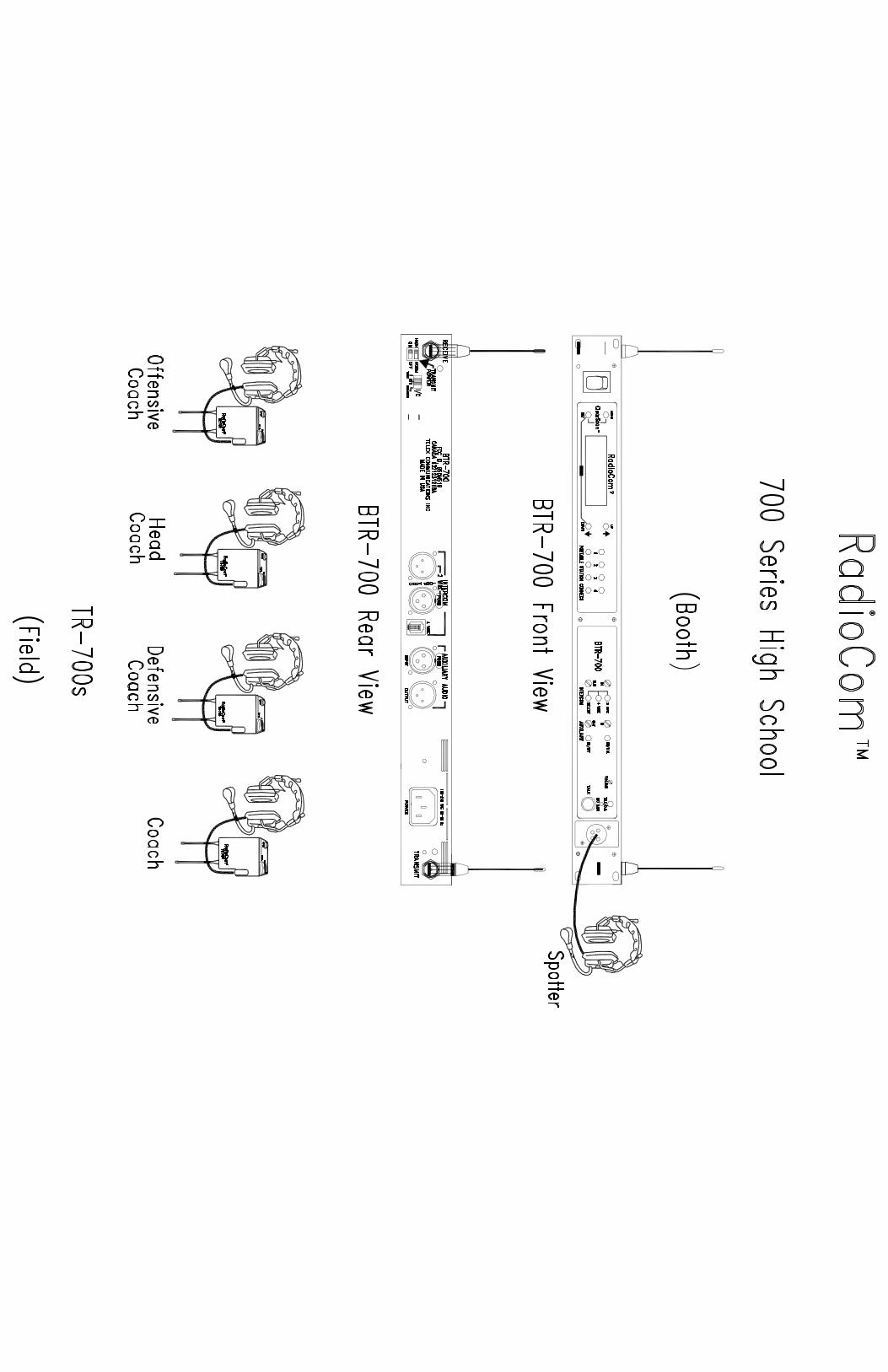
RadioCom™ Single Channel Systems700 Series UHF and 300 Series VHF Wireless Intercom
The wireless intercom examples shown, represent a basic system. They are single channelintercom systems and are shown independent of any wired intercom system. These systems can alsobe linked with Audiocom or RTS PL (Party-Line) intercom systems or with RTS Matrix intercomsystems.
Up to four TR beltpack transceivers can be used with the BTR base station with full duplexcommunications. All TR beltpacks will share a single audio channel with the BTR base station.
Both of these systems offer a cost effective solution for budget-minded applications that do notdemand more complex capabilities. The 300 series intercom is provided on fixed frequencies whilethe 700 series is frequency-agile in 18 MHz bands.
The systems shown in these examples are marked for a High School Football application,however, these stand-alone systems can be applied to churches, schools, auditoriums, or industrialapplications.
35

RadioCom™ Two Channel Systems800 Series UHF Wireless Intercom
The BTR-800 system adds a second audio channel providing communications to either audiochannel “A” or audio channel “B”. Like the 300 and 700 series wireless intercom systems, the 800series can be used as a stand-alone system or can be linked with Party-Line or Matrix wired inter-coms.
A further example of the 800 series wireless intercom system documents an interface with anAudiocom PL intercom. The example shows two BP-2002 two-channel beltpacks and two BP-1002single-channel beltpacks daisy-chained together with XLR cables to a US-2002 User Station and aPS-2001L Power Supply. The PL intercom is connected in series with a BTR-800 wireless intercombase station with four wireless beltpacks.
The wireless beltpacks shown, provide the user the ability to select which audio channel tocommunicate with. Up to four beltpacks can operate with a BTR-800 in full duplex. The TR-800provides communications with either audio channel “A” or audio channel “B”. You can listen or talkback to either audio channel, but not both at the same time.
Also shown, is the TR-825. The TR-825 can provide communication with audio channel “A” oraudio channel “B” or a mix of audio channels “A” & “B”. When the TR-825 is configured with a 5-pinXLR connector for operation with a Binaural (stereo) headset, the audio will be ‘split’ where youreceive audio channel “A” in your left ear cup and audio channel “B” in your right ear cup. You canlisten or talk back to either audio channel independently or simultaneously.
An advantage of the BTR-800 is you can configure different beltpacks to operate with yoursystem. You can operate TR-825s, for those users who need to talk back and listen on two audiochannels simultaneously, or TR-800s for simple two channel operation. You can also operate the TR-700 single channel beltpack with the BTR-800 for those user who only need access to one audiochannel. Additionally, the BTR-800 can accommodate multiple beltpacks operating in push-to-transmit mode.
The 800 series wireless intercom is frequency agile in 18 MHz bands and is provied with 36 pre-programmed frequency groups for easy selection and operation.
Like the 700 and 300 series wireless intercom systems, the 800 system can be configured forhigh school or small college football applications, as well as be configured for churches, schools,auditoriums, or industrial environments.
38


RadioCom™ Two Channel Systems500 Series UHF and 600 Series Encrypted UHF Wireless Intercom
The 500 and 600 series offers the ultimate in wireless intercom expandability. These systemscan be operated stand-alone or linked with PL or Matrix intercoms. The 500 and 600 series intercomsare unique in that each beltpack communicates with a matching base station (one to one) on twoseparate audio channels and are frequency-agile between two selectable frequencies. The 500 and600 series can be expanded for up to 12 systems to be used simultaneously.
The 600 series includes a unique digital encryption process for those who need secure full-duplex communications. Over 65,000 code settings can be selected by means of switches that arelocated on the units.
In the first example, the 600 series is shown as a High School Football stand-alone system.Typically, the BTR-600 base stations are located in the coaches booth with the TR-600 belpacks wornby the coaches on the field.
The last example depicts a large college layout with seven coaches on wired intercombeltpacks, located in the coaches booth, and eight coaches on wireless beltpacks, located on thefield. This system interfaces with four channels of Party-Line intercom. The BTR-600s interface withan AC-600. antennae splitter/combiner, to reduce the number of antennas required to one-transmitand one-receive. In this example, the ALP-600 bi-directional log periodic antenna is shown, whichprovides excellent coverage on a sideline.
Other applications for the 500 and 600 series intercom would be where one to one communica-tions are critical, such as nuclear power generating plants or other industrial applications.
41


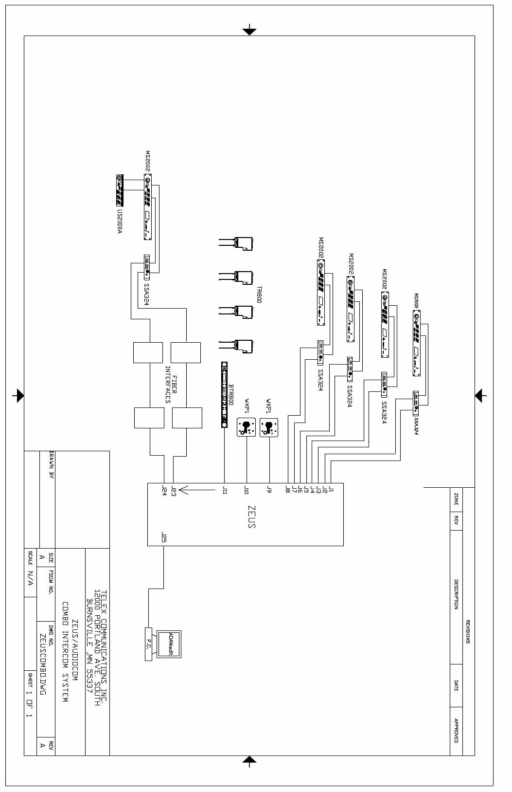
Zeus / Audiocom Combo Intercom System
This system is COMPLETELY unlike any of the previous systems.
Whereas the previous systems had “at their heart” some form of an Audiocom Master Station,this system uses an RTS Zeus Matrix Intercom System.
This is intended as only a VERY BRIEF introduction to Matrix Intercom Systems, so we willkeep our technical discussions to a minimum.
In broad concepts, TW or Party-Line Intercom systems are very similar to multiple extensionson the same telephone line; all participants hear the same conversation, and hear each other.
A Matrix Intercom System is much more like multiple telephones with separate telephonenumbers connected through the telephone company. Each user has the option of deciding who andwhen they want to talk to, whether they want to talk privately or in conference, and whether theywant to allow other parties to listen in.
The other feature of a Matrix System is hinted at by its other commonly used name “Four Wire”.Just as Party-Line intercoms are referred to as “TW” for two wire, this refers to how the audio isdistributed. In TW or Party-Line systems, the talk and listen audios are scrambled together, sharinga common pair of wires. In a Matrix or Four Wire system, the talk from a given user is on one pair,and the listen is on a second pair.
As in a previous drawing, we had to interface TW intercom to fiber (fiber like Four Wire sys-tems, having separate Talk and Listen paths), a Hybrid or System-to-System Adapter (SSA) isrequired to convert TW to Four Wire.
On the following diagram, you see when we connect a channel of TW to a channel of Four Wirewe use an SSA.
In a matrix system (such as Zeus), the users connect to other users by pressing keys or but-tons dedicated to those users (like speed dial buttons on a phone). Who those users are, whetherthey are individuals or conferences, or they function as IFBs, is a function of how the computer(inside Zeus) is programmed. This computer is programmed using a software program called AZedit(formerly known as ADAM-Edit), provided by Telex with each matrix intercom.
On the system drawing, J1 through J24 represent the 24 channels that Zeus can support.These 24 channels can correspond to 24 Matrix User Stations (key panels, such as the WKP-1 unitspictured) or can be fed through SSA units to feed channels of Audiocom or other Party-Line sys-tems. In the examples shown, a single channel from Zeus (for example, J1) goes through onechannel of an SSA-324 to one channel of the MS-2002. In most real world applications, the MS-2002 would also feed a number of other TW user stations (i.e., beltpacks or wall stations), so theTW “side” of the system could function independently as a normal Party-Line system. The advan-tage, being able to connect and communicate with any of the other 23 channels that Zeus offers.
It is useful to think of Zeus as a routing switcher for the other intercom channels, or as anautomated, programmable version of the IC-6SX shown on an earlier diagram.
44

When designing or specifying an intercom system, consider this - “An intercom system willLIKELY consist of elements which may include Party-Line Systems, Matrix Systems, WirelessSystems and Interfaces”. If, as in many of the earlier examples, the number of individual channels issmall, and the configuration of those channels is well defined an unlikely to change often, then amatrix intercom is LIKELY to be superfluous.
If, on the other hand, the system requirements point to a large number (greater than eight orten) channels, and the daily needs for which groups need to talk with, then the versatility offered bya matrix intercom system is worth the time, money and effort to design it.
45

Cable Diagrams
This drawing shows the various cable connections as noted on the first 13 drawings.
47


![AudioCom Training rev3 - textfiles.compdf.textfiles.com/manuals/STARINMANUALS/Telex Intercom/Manuals... · 1 Telex Intercom 1]Small System Intercom AudioCom RTS-TW 2] Large System](https://img.dokumen.tips/doc/110x75/5b25fa067f8b9ad4348b517a/audiocom-training-rev3-intercommanuals-1-telex-intercom-1small-system.jpg)