Embed Size (px)
Citation preview
1
Wireless Intercom Systems
RadioComTM
Principles of RF
What it is and how it works!
2
What is RF?
RF is short for Radio Frequency. Radio frequencies are part of the electromagnetic spectrum. They are different from audio frequencies because of two main factors:Frequency (usually higher)Medium of propagation (method of transmission)
Electromagnetic Spectrum
The electromagnetic spectrum is made up of signals whose frequency can be as low as a 1 Hz (Hertz) or as high as cosmic rays.
3
Electromagnetic Waves
Composed of an electric (electro) and magnetic components. These are sometimes referred to as the E field (electric) and H field (magnetic). 90° of separation between E and H fields.Depending on the frequency, the ratio of the amplitudes of the E and H fields will vary.
Field Ratios
The higher the frequency, the stronger the E field and the weaker the H field.The lower the frequency, the stronger the H field and the weaker the E field.The field ratios are important because they control how the wave behaves and therefore can be the difference between a system working and not working.
4
Wave Propagation
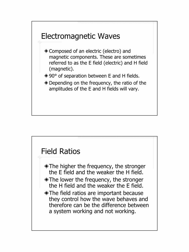
Electromagnetic waves propagate perpendicular to the E and H fields.
Basic RF System
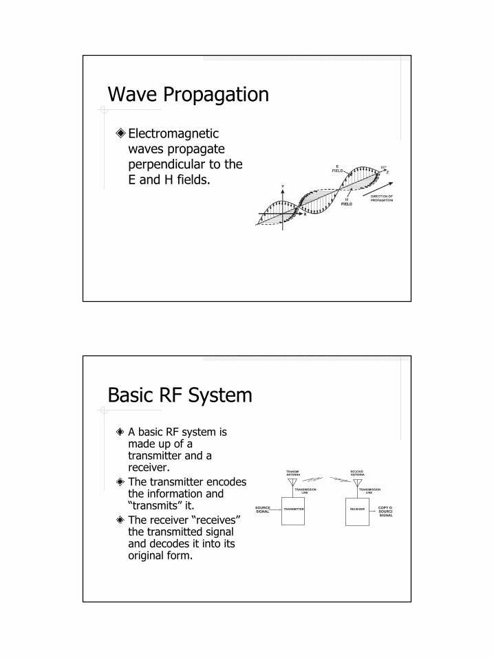
A basic RF system is made up of a transmitter and a receiver.The transmitter encodes the information and “transmits” it.The receiver “receives” the transmitted signal and decodes it into its original form.
TRANSMITTER
RECEIVERANTENNA
TRANSMITANTENNA
TRANSMISSIONLINE
TRANSMISSIONLINE
RECEIVERSOURCESIGNAL
COPY OFSOURCESIGNAL
5
The Transmitter
Takes the source information in (audio, data, etc…)Modulates (encodes) the RF wave with the information.Delivers the RF wave (signal) to the transmit (TX) antenna.
The Receiver
Gathers in the RF wave (signal) from the receive (RX) antenna.Demodulates (decodes) the RF wave with the information.Outputs a copy of the original source information (audio, data, etc…)
6
What Happens in the Middle?
The RF wave travels between the transmitter and receiver via the propagation path.The waves travel like the waves from a pebble in a pond.• Moves away equally in all directions• Each vector moves away in a straight line.• The signal gets weaker as it moves away.
The Inverse Square Law
The rate at which the RF wave becomes weaker can be calculated via the inverse square law:
(1/D2) x TX Power = Power at path endWhere D is the distance traveled.
Twice as far doesn’t mean half as strong!
7
An Example
Path Calculation A
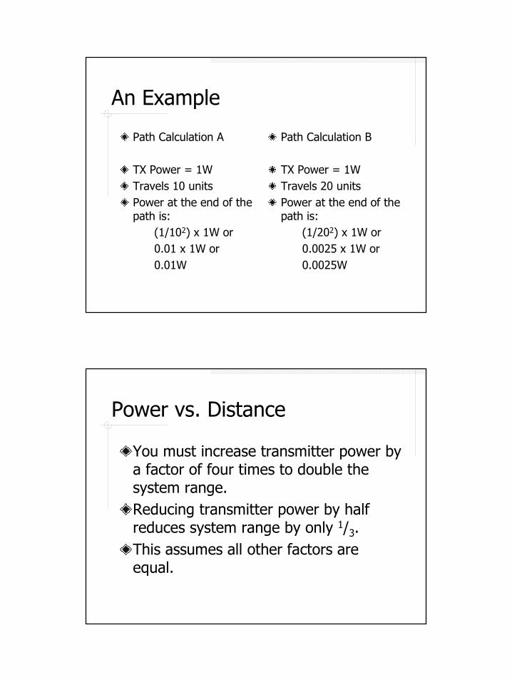
TX Power = 1WTravels 10 unitsPower at the end of the path is:
(1/102) x 1W or0.01 x 1W or0.01W
Path Calculation B
TX Power = 1WTravels 20 unitsPower at the end of the path is:
(1/202) x 1W or0.0025 x 1W or0.0025W
Power vs. Distance
You must increase transmitter power by a factor of four times to double the system range.Reducing transmitter power by half reduces system range by only 1/3.This assumes all other factors are equal.
8
Polarization
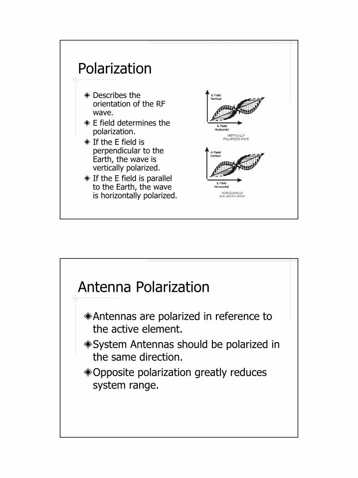
Describes the orientation of the RF wave.E field determines the polarization.If the E field is perpendicular to the Earth, the wave is vertically polarized. If the E field is parallel to the Earth, the wave is horizontally polarized.
Antenna Polarization
Antennas are polarized in reference to the active element.System Antennas should be polarized in the same direction.Opposite polarization greatly reduces system range.
9
Antenna Types
There are two basic types of antennas:
1. Omnidirectional2. Directional
All antennas have a driven element.
Omnidirectional Antennas
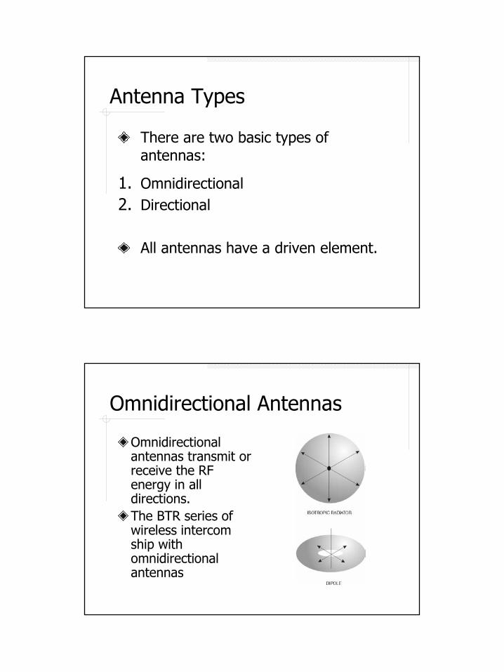
Omnidirectional antennas transmit or receive the RF energy in all directions.The BTR series of wireless intercom ship with omnidirectional antennas
10
Directional Antennas
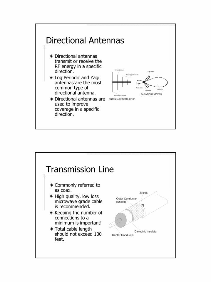
Directional antennas transmit or receive the RF energy in a specific direction.Log Periodic and Yagi antennas are the most common type of directional antenna.Directional antennas are used to improve coverage in a specific direction.
Reflective Element
Focusing Elements
Driven Elemen
ANTENNA CONSTRUCTION
RADIATION PATTERN
Side-lobes
Main-lobeRear-lobe
Antenna
Transmission Line
Commonly referred to as coax.High quality, low loss microwave grade cable is recommended.Keeping the number of connections to a minimum is important!Total cable length should not exceed 100 feet.
Outer Conductor(Shield)
Jacket
Dielectric InsulatorCenter Conductor
11
Splitting Antennas
Requires the use of a splitter. (Active or passive splitters exist.)Splitting antennas is recommended for receive antennas when coverage is an issue. Some signal loss will occur.Splitting antennas for the transmit side is only recommended in extreme cases since significant power loss will occur.Leaky coax can be used in certain situations.
Combining Antennas
Sometimes referred to as community antennasCan be used to reduce the number of antennas in a system.Requires a good combiner (preferably active).Potential exists for intermodulation.
12
Polarization vs. Phase
Polarization
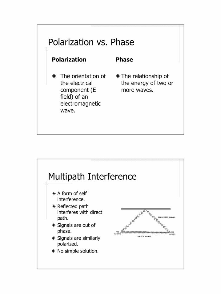
The orientation of the electrical component (E field) of an electromagnetic wave.
Phase
The relationship of the energy of two or more waves.
Multipath Interference
A form of self interference.Reflected path interferes with direct path.Signals are out of phase.Signals are similarly polarized.No simple solution.
REFLECTED SIGNAL
TXAntenna
DIRECT SIGNAL
RXAntenna
13
Receiver Desensing
Transmitter energy overloads a receiver.Doesn’t have to be exactly on receiver’s frequency.Small amounts of power can still mean a big problem.Solved by separation and in extreme cases filtering.
Intermodulation
What is it?
Intermodulation occurs when two or more frequencies mix in a non-linear device and produce a number of related frequencies known as intermodulation products (Intermod for short).
14
Intermodulation
How does it happen?
Intermodulation interference takes place when at least two transmitters are broadcasting at the same time on frequencies that have a definite, calculable relationship with the affected receiver.
Intermodulation
Where does it happen?
Intermod products are not created in the air. They are the result of the mixing of signals in non-linear devices such as transmitter output amplifiers and receiver input amplifiers or other usually active elements.
15
Intermodulation
How can it be avoided?
1. Pick frequencies that are known to work in the presence of each other without creating intermod.
2. Choose equipment with well designed receivers and transmitters with appropriate passive filtering.
3. Manage the positioning of antennas and beltpacks within the system to optimize operational potential.
Intermodulation
What should I do if I think intermod is occurring?
1. Try turning off one or more transmitters and see if the problem disappears.
2. Try repositioning antennas and/or equipment.3. Gather a list of frequencies in use (i.e. wireless
microphones, wireless intercom, etc…) and consult with a system engineer or other technical support person who can run an intermod calculation.
16
Frequency Coordination
An important first step in setting up a system. A coordinated system will keep the number of returns, re-crystalings, and tech support calls to a minimum.Before you call gather the following info:
1. Address where the system will be used. If it is a traveling system say so…
2. The frequencies of any additional wireless units (microphones, intercom, etc…) that may be used in conjunction with the new equipment.
Analog (NTSC) vs. Digital (DTV)
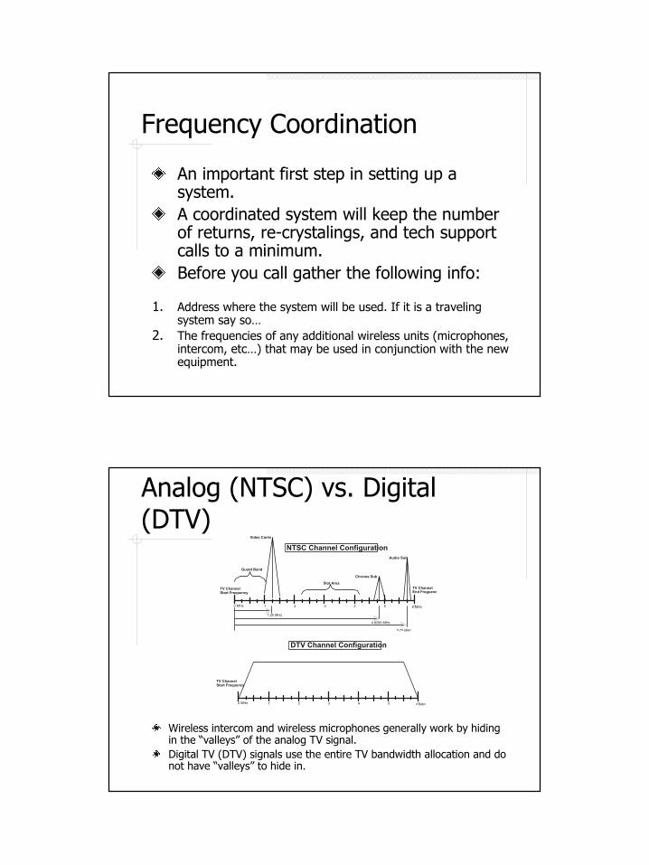
Wireless intercom and wireless microphones generally work by hiding in the “valleys” of the analog TV signal.Digital TV (DTV) signals use the entire TV bandwidth allocation and do not have “valleys” to hide in.
TV ChannelStart Frequency
0 MHz
1.25 MHz
4.8295 MHz
5.75 MHz
6 MHz1 2 3 4 5 1
Guard Band
Chroma Sub
Audio Sub
TV ChannelEnd Freguenc
Video Carrie
NTSC Channel Configuration
Slot Area
TV ChannelStart Frequency
0 MHz 6 MHz1 2 3 4 5 1
DTV Channel Configuration
17
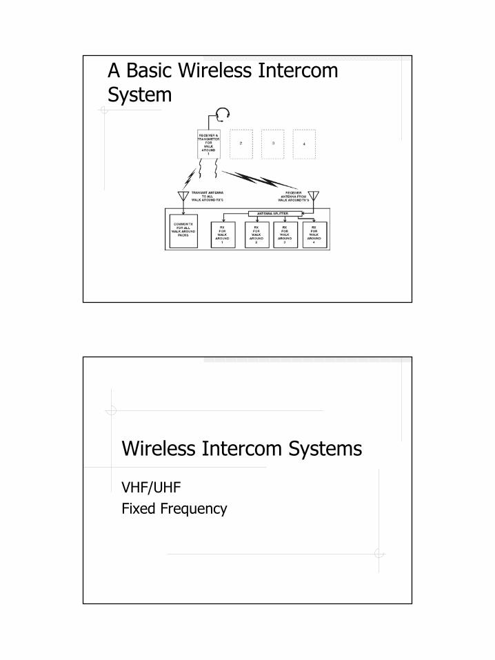
A Basic Wireless Intercom System
Wireless Intercom Systems
VHF/UHF Fixed Frequency
18
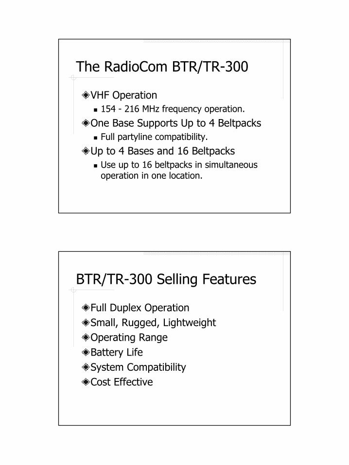
The RadioCom BTR/TR-300
VHF Operation� 154 - 216 MHz frequency operation.
One Base Supports Up to 4 Beltpacks� Full partyline compatibility.
Up to 4 Bases and 16 Beltpacks� Use up to 16 beltpacks in simultaneous
operation in one location.
BTR/TR-300 Selling Features
Full Duplex OperationSmall, Rugged, LightweightOperating RangeBattery LifeSystem CompatibilityCost Effective
19
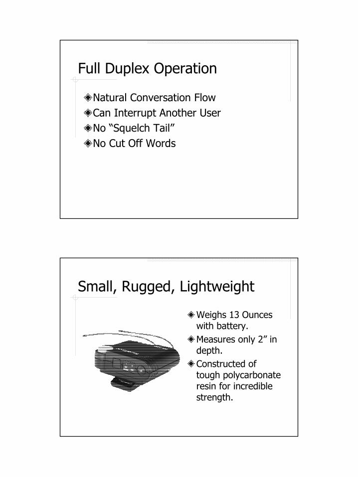
Full Duplex Operation
Natural Conversation FlowCan Interrupt Another UserNo “Squelch Tail”No Cut Off Words
Small, Rugged, Lightweight
Weighs 13 Ounces with battery.Measures only 2” in depth.Constructed of tough polycarbonate resin for incredible strength.
20
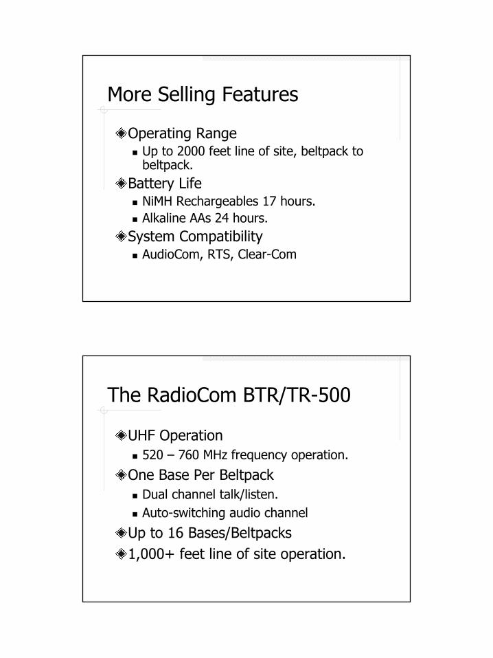
More Selling Features
Operating Range� Up to 2000 feet line of site, beltpack to
beltpack.Battery Life� NiMH Rechargeables 17 hours.� Alkaline AAs 24 hours.System Compatibility� AudioCom, RTS, Clear-Com
The RadioCom BTR/TR-500
UHF Operation� 520 – 760 MHz frequency operation.
One Base Per Beltpack� Dual channel talk/listen.� Auto-switching audio channel
Up to 16 Bases/Beltpacks1,000+ feet line of site operation.
21
The RadioCom BTR/TR-600
Same great features and performance as the BTR/TR-500.Uses 24-bit digital encryption technique.� 65,000 code setting that can be changed
on the fly via four cipher code switches
Slightly more system noise than BTR/TR-500 system due to encryption.
Mirrored Belt Packs
Sometimes referred to as a tour guide setup.Available on models:
TR-300TR-500TR-600
22
Wireless Intercom Systems
UHF Frequency Agile
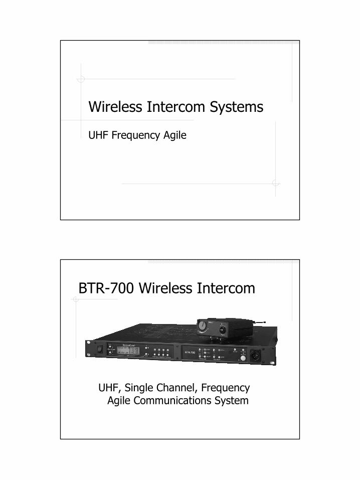
BTR-700 Wireless Intercom
UHF, Single Channel, Frequency Agile Communications System
23
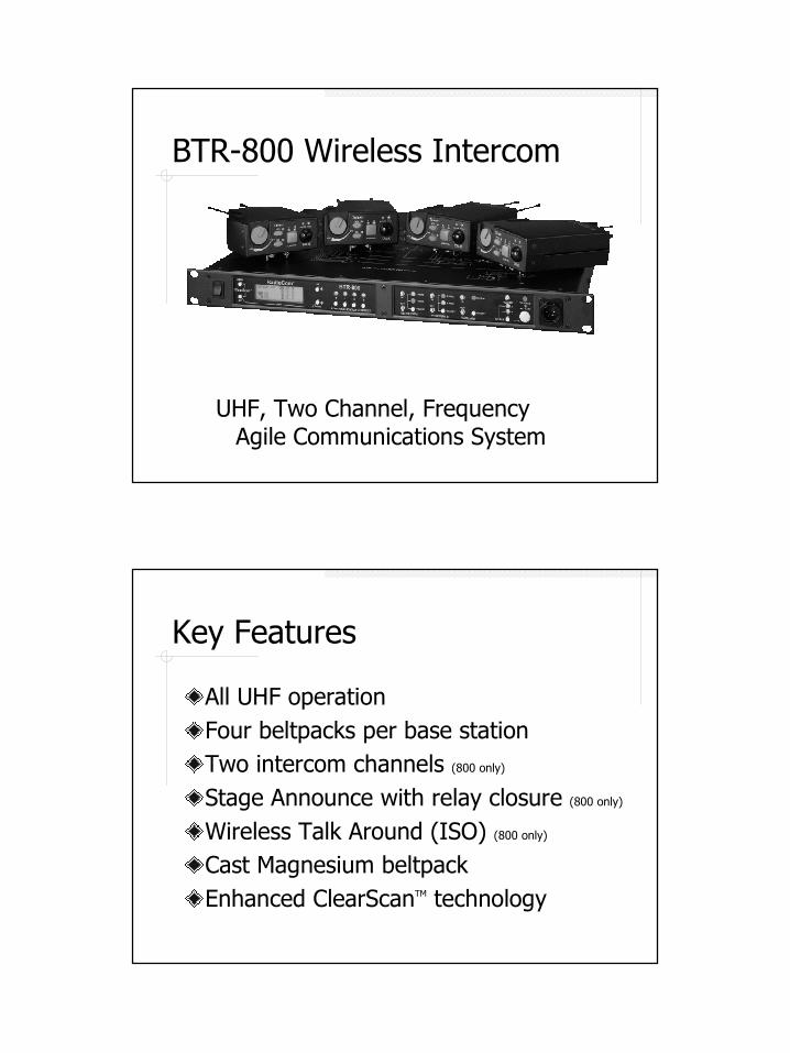
BTR-800 Wireless Intercom
UHF, Two Channel, Frequency Agile Communications System
Key Features
All UHF operationFour beltpacks per base stationTwo intercom channels (800 only)
Stage Announce with relay closure (800 only)
Wireless Talk Around (ISO) (800 only)
Cast Magnesium beltpack Enhanced ClearScanTM technology
24
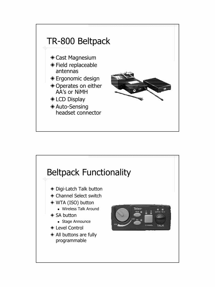
TR-800 Beltpack
Cast MagnesiumField replaceable antennasErgonomic designOperates on either AA’s or NiMHLCD DisplayAuto-Sensing headset connector
Beltpack Functionality
Digi-Latch Talk buttonChannel Select switchWTA (ISO) button� Wireless Talk Around
SA button� Stage Announce
Level ControlAll buttons are fully programmable
25
Intelligent Power ControlTM
Automatically reduces beltpack power 10dB from 50mW to 5mW when beltpack is in close proximity to base.Reduces desensing created by near/far situationsSaves battery life.Reduces intermodulation
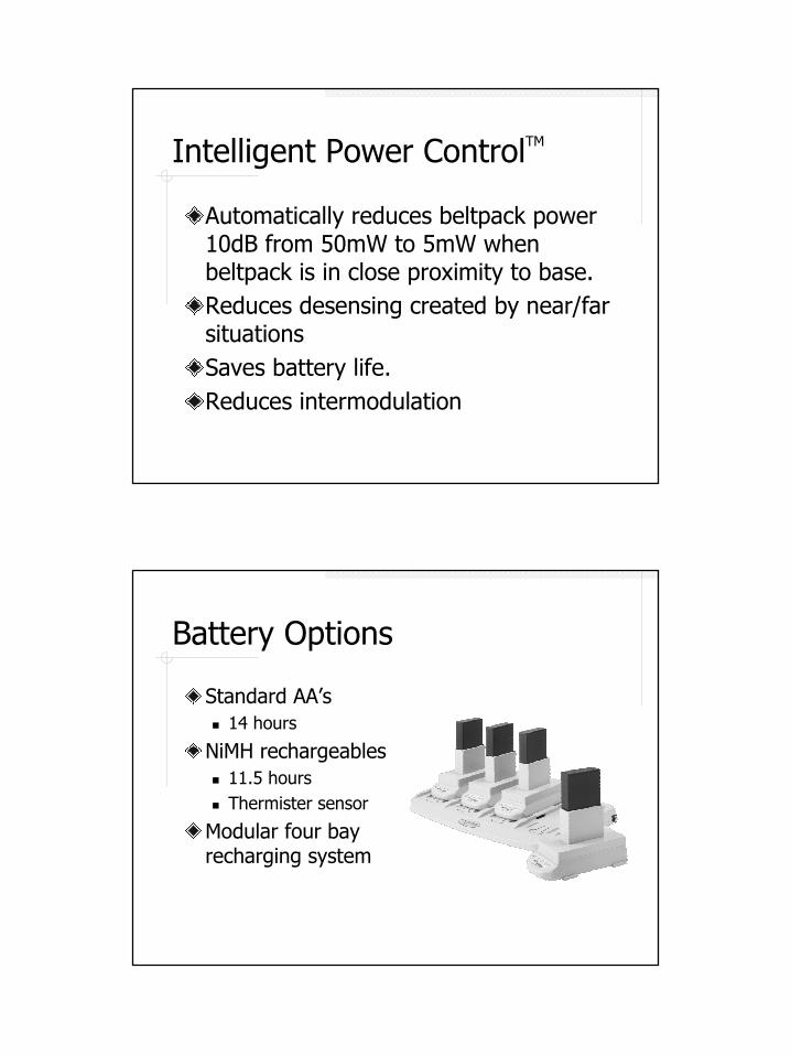
Battery Options
Standard AA’s� 14 hours
NiMH rechargeables� 11.5 hours� Thermister sensor
Modular four bay recharging system
26
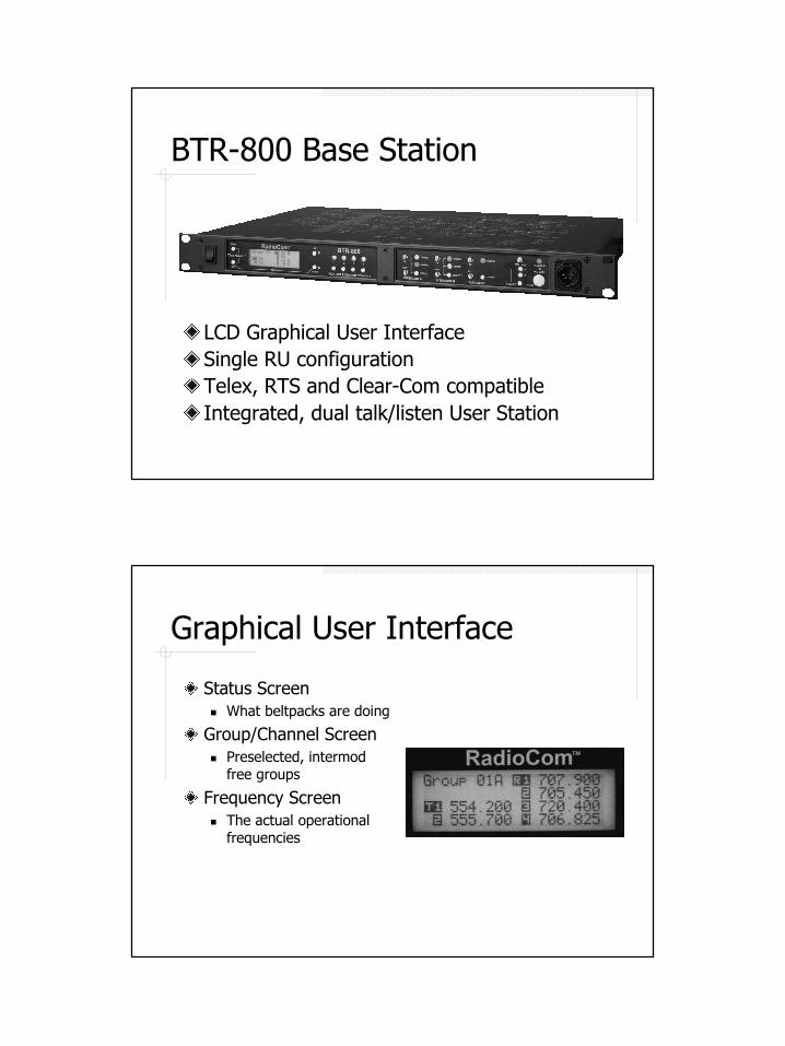
BTR-800 Base Station
LCD Graphical User InterfaceSingle RU configurationTelex, RTS and Clear-Com compatibleIntegrated, dual talk/listen User Station
Graphical User Interface
Status Screen� What beltpacks are doing
Group/Channel Screen� Preselected, intermod
free groups
Frequency Screen� The actual operational
frequencies
27
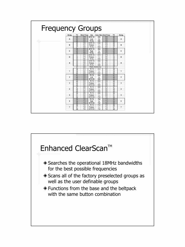
Frequency GroupsDesig TV Strat Freq Use Telex BandEnd Freq TV Desig
22 518 BTR TX 518 524 22A 23 524 Low to 530 23 A
24 530 TR Rx 536 536 2425 536 BTR TX 536 542 25
B 26 542 Future to 548 26 B27 548 TR Rx 554 554 2728 554 BTR TX 554 560 28
C 29 560 High to 566 29 C30 566 TR Rx 572 572 3031 572 BTR TX 572 578 31
D 32 578 Future to 584 32 D33 584 TR Rx 590 590 3334 590 BTR TX 590 596 34
E 35 596 Future to 602 35 E36 602 TR Rx 608 608 3637 608 614 3738 614 TR TX 614 620 38
1 39 620 Future to 626 39 140 626 BTR RX 632 632 4041 632 TR TX 632 638 41
2 42 638 Low to 644 42 243 644 BTR RX 650 650 4344 650 TR TX 650 656 44
3 45 656 Future to 662 45 346 662 BTR RX 668 668 4647 668 TR TX 668 674 47
4 48 674 Future to 680 48 449 680 BTR RX 686 686 4950 686 TR TX 686 692 50
5 51 692 Future to 698 51 552 698 BTR RX 704 704 5253 704 TR TX 704 710 53
6 54 710 High to 716 54 655 716 BTR RX 722 722 5556 722 TR TX 722 728 56
7 57 728 Future to 734 57 758 734 BTR RX 734 740 58
Radio Astronomy
Enhanced ClearScanTM
Searches the operational 18MHz bandwidths for the best possible frequenciesScans all of the factory preselected groups as well as the user definable groupsFunctions from the base and the beltpack with the same button combination
28
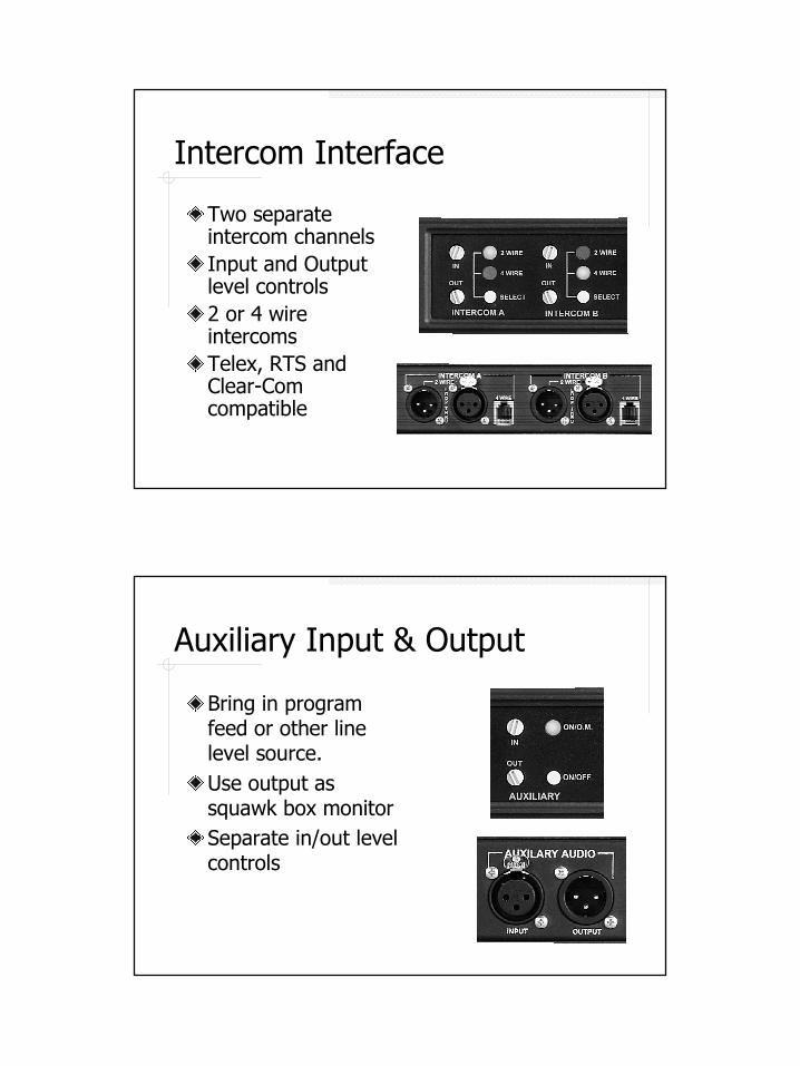
Intercom Interface
Two separate intercom channelsInput and Output level controls2 or 4 wire intercomsTelex, RTS and Clear-Com compatible
Auxiliary Input & Output
Bring in program feed or other line level source.Use output as squawk box monitorSeparate in/out level controls
29
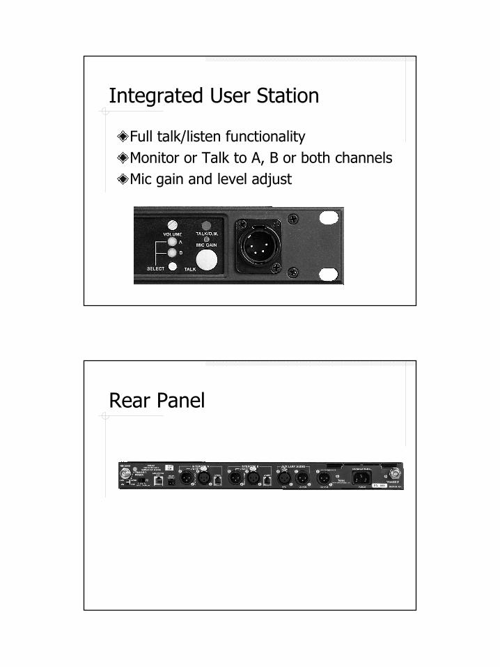
Integrated User Station
Full talk/listen functionalityMonitor or Talk to A, B or both channelsMic gain and level adjust
Rear Panel
30
Wireless Intercom Systems
Accessories
Antennas & Cable
Directional antennas (Yagi & Log Periodic).Replacement base station and beltpack antennas.Low-loss cable in 25, 50, 75, and 100 foot lengths.SC-600 Antenna combiner for BTR-500, BTR-600, and BTR-700 systems.
31
Other Accessories
Power supplies.Battery packs.Belt clips.
Wireless IFB Systems
VHF Switch Selectable Frequency
32
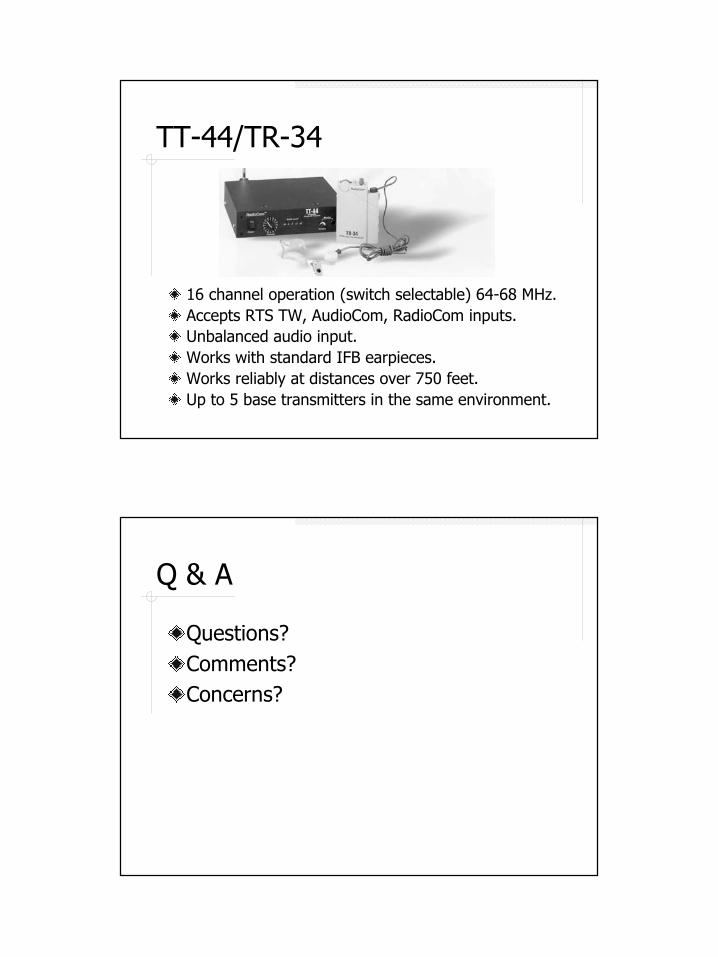
TT-44/TR-34
16 channel operation (switch selectable) 64-68 MHz.Accepts RTS TW, AudioCom, RadioCom inputs.Unbalanced audio input.Works with standard IFB earpieces.Works reliably at distances over 750 feet.Up to 5 base transmitters in the same environment.
Q & A
Questions?Comments?Concerns?