Embed Size (px)
Citation preview

VMware Cloud Foundation Overviewand Bring-Up Guide
VMware Cloud Foundation 2.1
This document supports the version of each product listed andsupports all subsequent versions until the document isreplaced by a new edition. To check for more recent editions ofthis document, see http://www.vmware.com/support/pubs.
EN-002378-02

VMware Cloud Foundation Overview and Bring-Up Guide
2 VMware, Inc.
You can find the most up-to-date technical documentation on the VMware Web site at:
http://www.vmware.com/support/
The VMware Web site also provides the latest product updates.
If you have comments about this documentation, submit your feedback to:
Copyright © 2015 – 2017 VMware, Inc. All rights reserved. Copyright and trademark information.
VMware, Inc.3401 Hillview Ave.Palo Alto, CA 94304www.vmware.com

Contents
About the VMware Cloud Foundation Overview and Bring-Up Guide 5
1 About VMware Cloud Foundation 7
Features and Benefits 9Cloud Foundation Use Cases 10Private Cloud Deployment Options 12Physical Topology 13Network Topology 15Storage Topology 15
2 Cloud Foundation Architecture 17
VIA 19SDDC Manager 19Hardware Management Services and Hardware Plugins 21SDDC Components of Cloud Foundation 21
3 Preparing your Site for the Cloud Foundation System 23
4 Cloud Foundation Initial Bring-Up 25
Connect Rack 1 to Your Power Source and Network 26Initiate the Cloud Foundation Bring-Up Process on Rack 1 27Locate SDDC Manager IP Address 46Change Passwords of Rack Components 47Change SDDC Manager Password 48Copy Backup File to an Accessible Location 49
5 Adding Racks to your Cloud Foundation System 51
Connect Rack 2 to Spine Switches 51Power on Rack 2 52Bootstrap Additional Rack 52Manual Steps for Rack Addition 55Initiate the Bring-Up Process on Additional Rack 56Changing Passwords of Rack Components 61Change SDDC Manager Password on Each Additional Rack 61
6 Alerts List 63
7 Troubleshooting Cloud Foundation Deployment 67
Manually Power On SDDC Manager VM When Setting Up Your Cloud Foundation System 67Restart HMS 68Retry If Bring-Up Fails During NFS Datastore Creation 68
VMware, Inc. 3

Retry If Bring-Up Fails During NSX Power Up 68
8 Additional VMware Product Documentation 71
9 Example ToR Switch Output for L3 Configuration on Cisco ToR Switches
(9372) 73
10 Glossary 77
Index 79
VMware Cloud Foundation Overview and Bring-Up Guide
4 VMware, Inc.

About the VMware Cloud Foundation Overviewand Bring-Up Guide
The VMware Cloud Foundation Overview and Bring-Up Guide provides an overview of theVMware Cloud Foundation product and its components and describes the steps for setting up andconfiguring a Cloud Foundation system.
Intended AudienceThe VMware Cloud Foundation Overview and Bring-Up Guide is intended for data center cloud administratorswho deploy an Cloud Foundation system in their organization's data center. The information in this guide iswritten for experienced data center cloud administrators who are familiar with:
n Concepts of virtualization and software-defined data centers
n Networking and concepts such as uplinks, NICs, and IP networks
n Hardware components such as top-of-rack (ToR) switches, spine switches, servers with direct attachedstorage, cables, and power supplies
n Methods for setting up physical racks in your data center
n Using the VMware vSphere® Web Client™ to work with virtual machines
Related PublicationsThe Administering VMware Cloud Foundation contains detailed information about how to administer andoperate your data center's deployed Cloud Foundation system.
Your Cloud Foundation system includes various VMware software products and components. You can findthe documentation for those VMware software products at www.vmware.com/support/pubs.
VMware Technical Publications GlossaryVMware Technical Publications provides a glossary of terms that might be unfamiliar to you. For definitionsof terms as they are used in VMware technical documentation, go to http://www.vmware.com/support/pubs.
VMware, Inc. 5

VMware Cloud Foundation Overview and Bring-Up Guide
6 VMware, Inc.

About VMware Cloud Foundation 1VMware Cloud Foundation is the unified SDDC platform for the private and public cloud. CloudFoundation brings together compute, storage, and network virtualization into a natively integrated stackthat can be deployed on-premises or run as a service from the public cloud.
APP
OSAPP
OSAPP
OSAPP
OSAPP
OSAPP
OS
SDDC Manager - Automated Lifecycle Management
Public cloud
NSX Virtual SANvSphere
Private cloud
The VMware Cloud Foundation Overview and Bring-Up Guide focuses on the private cloud use case.Deploying VMware Cloud Foundation on Qualified Hardware(http://link.brightcove.com/services/player/bcpid2296383276001?bctid=ref:video_deploy_cloud_foundation_hardware)
VMware, Inc. 7

To manage the logical infrastructure in the private cloud, Cloud Foundation augments the VMwarevirtualization and management components with a new component, SDDC Manager. SDDC Manager is thesingle interface for managing the infrastructure. From this interface, the IT administrator can provision newprivate cloud resources, monitor changes to the logical infrastructure, and manage lifecycle and otheroperational activities.
Figure 1‑1. Cloud Foundation Solution
Cloud Foundation(all vRack traffic stays inside)
Attached to corporate network through L2/L3 peering
This chapter includes the following topics:
n “Features and Benefits,” on page 9
n “Cloud Foundation Use Cases,” on page 10
n “Private Cloud Deployment Options,” on page 12
n “Physical Topology,” on page 13
VMware Cloud Foundation Overview and Bring-Up Guide
8 VMware, Inc.

n “Network Topology,” on page 15
n “Storage Topology,” on page 15
Features and BenefitsIn addition to the core features and capabilities provided by the individual components of the softwarestack, Cloud Foundation adds several unique capabilities.
Natively Integrated Software-Defined StackCloud Foundation delivers a natively integrated software-defined data center stack starting with the coreinfrastructure virtualization, vSphere, Virtual SAN and NSX, in addition to the SDDC Manager for lifecyclemanagement automation. Customers can flexibly upgrade individual components in the stack to highereditions and optionally deploy VMware vRealize Suite and VMware Horizon.
Automates Hardware and Software Bring-UpCloud Foundation automates the installation of the entire VMware software stack. Once the rack is installedand powered on and the networking is in place, SDDC Manager leverages its knowledge of the hardwarebill of materials and user-provided environmental information (e.g. DNS, IP address pool, etc.) to initializethe rack. Time savings varies by customer, but software installation time is estimated to be reduced fromseveral weeks to as little as two hours due to the automation of certain previously manual functions. Theseinclude provisioning workloads, including automated provisioning of networks, allocation of resourcesbased on service needs, and provisioning of end points. When the process completes, the customer has avirtual infrastructure ready to start deploying vSphere clusters and provisioning workloads.
Simplifies Resource Provisioning by Creating Workload DomainsCloud Foundation introduces a new abstraction, workload domains, for creating logical pools acrosscompute, storage, and networking. A workload domain is a policy based resource container with specificavailability and performance attributes that combines vSphere, vSAN and NSX into a single consumableentity. Each workload domain provides the needed capacity with specified policies for performance,availability, and security. For example, a cloud administrator can create one workload domain for testworkloads that have balanced performance and low availability requirements, while creating a separateworkload domain for production workloads requiring high availability and high performance.
SDDC Manager automatically implements a deployment workflow to translate the workload domainspecifications into the underlying pool of resources. Workload domains relieve a cloud administrator fromhaving to research and implement best practices needed to achieve operational goals.
A workload domain can be created, expanded, and deleted as part of the SDDC lifecycle operations.
Automates Lifecycle ManagementData center upgrades and patch management are typically manual, repetitive tasks that are prone toconfiguration and implementation errors. Validation testing of software and hardware firmware to ensureinteroperability among components when one component is patched or upgraded requires extensive qualityassurance testing in staging environments. Often strapped for time, IT must sometimes make the difficultdecision to deploy new patches before they are fully vetted or defer new patches, which slows down theroll-out of new feature or security and bug fixes. Both situations increase risk for the private cloudenvironment.
SDDC Manager automates upgrade and patch management for the SDDC software stack, thereby freeingresources to focus on business critical initiatives, while improving reliability and consistency.
Chapter 1 About VMware Cloud Foundation
VMware, Inc. 9

Lifecycle management in SDDC Manager can be applied to the entire infrastructure or to specific workloaddomains and is designed to be non-disruptive to tenant virtual machines (VMs). By utilizing live VMmigration, SDDC Manager can patch software to improve infrastructure security and reliability whilemaintaining tenant uptime.
Integrates Management of Physical and Virtual InfrastructureSDDC Manager understands the physical and logical topology of the software defined data center and theunderlying components’ relation to each other, and efficiently monitors the infrastructure to detect potentialrisks, degradations and failures. SDDC Manager provides stateful alert management to prevent notificationspam on problem detection. Each notification includes a clear description of the problem and providesremediation actions needed to restore service. Degradations or failures are aggregated and correlated toworkload domains to enable a clear view of the impact of any issue to the business services being deployedwithin a domain. Therefore, SDDC Manager can greatly reduce the mean time to resolution acrossorganizational and technology silos.
Scalability and PerformanceCloud Foundation delivers a private cloud instance that can be easily deployed within an existing corporatenetwork. Based on a scale-out, hyper-converged architecture, a Cloud Foundation implementation can startas small as 4servers, and can scale out to multiple racks. Additional capacity and performance can easily beadded linearly in increments as small as one server at a time within a single rack, scaling out to 8 full racksper SDDC Manager instance. Cloud Foundation automatically discovers any new capacity and adds it intothe larger pool of available capacity for use.
Cloud Foundation Use CasesCloud Foundation includes two pre-packaged workload domain types, Virtual Infrastructure (VI) andVirtual Desktop Infrastructure (VDI). A workload domain is a policy based resource container with specificavailability and performance attributes and combining vSphere, vSAN and NSX into single a consumableentity. The following sub-sections discuss how Cloud Foundation implements each of these workloaddomains.
Virtual InfrastructureWith Cloud Foundation, you have a turnkey solution to run your SDDC infrastructure. Cloudadministrators have the ability to expand and contract the underlying infrastructure to meet their changingbusiness needs. With a cloud that is based on the market leading virtualization platform, lines of businesshave the flexibility to deploy a wide variety of operating systems and application stacks within the tenantVMs. Virtual infrastructure administrators can integrate with and monitor the underlying infrastructureusing a common monitoring tool set that aggregates and correlates across physical and virtualinfrastructure. In addition, you have the flexibility to integrate their vSphere compatible tools directly withvCenter Server.
VI configures a flexible virtual datacenter including the following:
n Ability to deploy and configure OS instances in the form of VMs with vCPUs, memory, and storageincluding networking resources.
n Internet connectivity with a built-in IPAM (IP Address Management) solution.
You can acquire modular Cloud Foundation units to match your consumers' data center capacityrequirements and offer the resulting virtual infrastructure to your consumers with minimal overhead. SDDCManager deploys the following for a VI workload:
n Physical compute
The servers specified by the administrator are deployed. Each server includes processing, storage, andnetwork connectivity.
VMware Cloud Foundation Overview and Bring-Up Guide
10 VMware, Inc.

n Virtual infrastructure
One vCenter Server is deployed per workload domain, which connects to the Platform ServicesController in the management domain for credentials and licenses. It creates workload domainsaccording to the specifications, adding hosts and creating vSAN datastores from the storage on thosehosts. It also deploys and configures NSX vSwitches into the ESXi instance on each host.
n Physical networking
SDDC Manager uses the Hardware Management Services ( HMS) to configure the ToR switches toaccept traffic for the VLANs created in the virtual infrastructure and to route traffic for the publiclogical networks of the workload domain.
n Management
Cloud Foundation allows administrators to monitor and manage the workload domain usingvRealize Operations Manager, and vRealize Log Insight.
Virtual Desktop InfrastructureWith Cloud Foundation, you can deliver virtual or hosted desktops and applications through a singleVirtual Desktop Infrastructure (VDI) platform with VMware VMware Horizon with View. End users canaccess all of their desktops and applications through a single unified workspace.
When you deploy a VDI workload, Cloud Foundation reserves the necessary hardware resources anddeploys the required SDDC components. Your Cloud Foundation system auto-configures the physicalinfrastructure. SDDC Manager deploys the following for a VDI workload:
n Physical compute
The servers specified by the administrator are deployed. Each server includes processing, storage, andnetwork connectivity.
n Virtual infrastructure
One vCenter Server is deployed per workload domain, which connects to the Platform ServicesController in the management domain for credentials and licenses. It creates workload domainsaccording to the specifications, adding hosts and creating vSAN datastores from the storage on thosehosts. It also deploys and configures NSX switches into the ESXi instance on each host.
n Physical networking
SDDC Manager uses the HMS to configure the switches to accept traffic for the VLANs created in thevirtual infrastructure and to route traffic for the public logical networks of the workload domain.
n Management
Cloud Foundation allows administrators to monitor and manage the workload domain usingvRealize Operations Manager, and vRealize Log Insight.
n VDI
Cloud Foundation is bundled with VMware Horizon with View and automates the deployment of ViewConnection Servers, security servers, App Volumes, Composer Server, and a DHCP Relay Agent.Cloud Foundation can create an initial desktop pool.
With VDI, you can:
n Create additional users for access to the VMware Horizon with View environment, connecting it to anLDAP or Active Directory server for authenticating enterprise users.
n Configure desktop environments including persistence, application access, etc.
Chapter 1 About VMware Cloud Foundation
VMware, Inc. 11

n Migrate VM templates from VDI infrastructure outside the workload domain into the virtual rackworkload domain(s). This is made possible because the SDDC Manager creates the management virtualnetwork as a public one (traffic can flow in and out of the workload domain and physical rack) andvCenter Server 6.0 allows VM migration between vCenter Servers. You cannot migrate VMs beingmanaged by another installation of VMware Horizon with View.
IT Automating ITvRealize Automation can be optionally added to the Cloud Foundation software stack.
Private Cloud Deployment OptionsCloud Foundation provides flexibility in choosing on-premises deployment options.
Customers begin by sizing their Cloud Foundation deployment to determine the number of physical serversin their rack. You then have two deployment options for Cloud Foundation
n Deploy the Cloud Foundation software on qualified hardware in your datacenter.
Customers can start with qualified hardware (qualified vSAN ready nodes and qualified switches) intheir datacenter, wire it up, and deploy the Cloud Foundation software stack on the ready system. Forinformation on qualified hardware, see VMware Compatibility Guide.
n Purchase a fully integrated system that combines software and hardware from select VMware partners.
The partner works with a VMware representative to complete the Site Readiness document. Thistranslates into a bill of materials (BoM) consisting of both hardware and software components. With thisBoM in hand, the partner assembles the rack and images it. The partner then ships the system,consisting of physical racks, servers, server sub-components, power distribution units, switchinginfrastructure and the Cloud Foundation software, to customers.
VMware Cloud Foundation Overview and Bring-Up Guide
12 VMware, Inc.

Physical TopologyCloud Foundation is a logical instance of up to eight physical racks.
Figure 1‑2. Physical Topology
KEMP
NICs CPU Memory SSD HDD Mgmt port
HMS
Cloud Foundation API
Cloud Foundation UIvRealize OperationvRealize Log Insight
Workload Management
NSX Manager
NSX
vCenter Server
VSAN
Har
dwar
e
vSphere
HMS
ManagementSwitch
Cloud Foundation API
VI / VDI
SDDC Manager
Virt
ualiz
atio
nO
pera
tions
and
Man
agem
ent
(OA
M)
Host 0 appliance
Spine SwitchesThe Cloud Foundation system contains two spine switches. These switches extend the network fabric of thetop of rack (ToR) switches between racks and are used for inter-rack connectivity only. The hardware vendorconnects the available uplink ports of the ToR switches to the spine switches.
Spine switches are required only in multi-rack installations of Cloud Foundation and are placed in thesecond rack.
Chapter 1 About VMware Cloud Foundation
VMware, Inc. 13

Management SwitchThe management switch provides Out-Of-Band (OOB) connectivity to the baseboard management controller(BMC) on each server.
The management network fabric does not carry vSphere management, vSAN, or vMotion traffic. That trafficresides on the network fabric created by the TOR and spine switches. As a result the management switch is anon-redundant component in the physical rack. If this switch goes down, some functionality such asmonitoring may not be available until it comes back up. Workloads will continue to run, but theinfrastructure associated with them cannot be modified or controlled.
Top of Rack SwitchesA physical rack contains two top of rack (ToR) switches, each of which has 48 10GE ports and at least 4 40GEuplink ports. The ToR and spine switches carry all network traffic from the servers including VM network,VM management, vSAN, and vMotion traffic. On rack 1 in a multi-rack Cloud Foundation, the ToRs alsocarry traffic to the enterprise network via two of the uplink ports. The ToR switches provide higherbandwidth as well as redundancy for continued operation in case one of the ToR switches goes down.
If the installation has spine switches, two uplink ports from each ToR switch on each rack are connected toeach spine switch.
ServersA physical rack must contain a minimum of four dual-socket 1U. You can incrementally add servers to therack up to a maximum of 32 servers.
All servers within a rack must be of the same model and type. The disk size and storage configuration mustbe identical as well. Memory and CPU (e.g. per CPU core count) between servers can vary. For supportedconfiguration, see VMware Compatibility Guide.
Management DomainSDDC Manager configures the first four servers in each physical rack into an entity called the managementdomain. After you deploy Cloud Foundation, you can expand the management domain.
The management domain manages the hosts in that rack. All disk drives are claimed by vSAN.
The management domain contains the following:
n vCenter Server Appliance(including both vCenter Server and Platform Services Controller as separateVMs) managing the vSphere cluster with HA and DRS enabled.
n The following VMs:
n NSX Manager
n vRealize Operations
n vRealize Log Insight
n SDDC Manager
VMware Cloud Foundation Overview and Bring-Up Guide
14 VMware, Inc.

Figure 1‑3. Management Domain Architecture
Management Cluster
NSX Manager SDDC Manager
vCenter Server vRealize Operations
Platform Services Controller
vRealize Log Insight
Host 1 Host 2 Host 3 Host 4
Management VSAN Datastore
Network TopologyAll hosts in a physical rack are connected to both the two ToR switches with 10Gb links. On each host, NICport 1 is connected to ToR switch 1 and NIC port 2 is connected to ToR switch 2 with Link Aggregation(LAG).
The BMC on each host is connected to the management switch over a 1G connection. This connection is usedfor OOB management. Both ToR switches are further connected to a pair of spine switches in a dual-LAGconfiguration using 40 G links. The spine switches are an aggregation layer for connecting multiple racks.
Cloud Foundation is designed to be resilient to certain network failures. The datapath between hosts andToR switches can tolerate a failure of one link between the host and ToR switches. Between the ToR andspine switches, the system can tolerate the failure of a ToR switch and/or spine switch.
Storage TopologyThe primary source of storage for Cloud Foundation is vSAN. For example, a 1U server can have 8 disks inthe capacity tier and 2 disks in the caching tier. All disks are claimed by vSAN for storage.
The amount of available physical storage in workload domains depends on the number of physical hosts.The amount of usable capacity depends on availability requirements.
Storage traffic is carried over the 10Gbps links between the hosts and ToR switches. All vSAN memberscommunicate over this 10Gbps network.
vSphere Network I/O Control (NIOC) can be enabled to allow network resource management to usenetwork resource pools to prioritize network traffic by type.
Chapter 1 About VMware Cloud Foundation
VMware, Inc. 15

VMware Cloud Foundation Overview and Bring-Up Guide
16 VMware, Inc.

Cloud Foundation Architecture 2Cloud Foundation is a logical instance of orchestrating, provisioning, and deploying an SDDC. It maps aconverged view of physical resources (e.g., CPU, memory, storage, and network) to a logical abstraction.Cloud Foundation overlays a software suite on top of the physical hardware for operations management,event reporting, and auditing. This enables Cloud Foundation to provide consistent hardware managementacross switches, servers, and storage, as well as a distributed management solution across your SDDC.
Though there is a management software stack on each physical rack, Cloud Foundation's distributedarchitecture provides the SDDC Manager as a single point-of-control web-based interface for managinginfrastructure and deploying workloads.
Figure 2‑1. Multi-Rack Setup
HardwareManagement
Cloud Foundation Multi-RackDiscovery and Management
Single Virtual Rack(ESXi, vSAN, NSX)
VMware, Inc. 17

The figure below shows the software components of Cloud Foundation and how they are mapped to thephysical hosts and switches in the rack.
Figure 2‑2. Cloud Foundation Software Stack
KEMP
NICs CPU Memory SSD HDD Mgmt port
HMS
Cloud Foundation API
SDDC Manager
Workflow Services Engine
Physical Resource Manager
Logical Resource Manager
Event Processing Manager
State Controller and Auditing
Resource Aggregation and Correlations Engine
Data Store
Cloud Foundation UI
vRealize Operation
vRealize Log Insight Workload Managment
Continousautomated
managementpolicies
NSX Manager
NSX
vCenter Server
VSANVSAN/NSX/
vSpherepolicies,
events
Hardwarecontroland events
Har
dwar
e
vSphere
This chapter includes the following topics:
n “VIA,” on page 19
n “SDDC Manager,” on page 19
n “Hardware Management Services and Hardware Plugins,” on page 21
n “SDDC Components of Cloud Foundation,” on page 21
VMware Cloud Foundation Overview and Bring-Up Guide
18 VMware, Inc.

VIAVIA is a virtual appliance used by system integrators or administrators deployingVMware Cloud Foundation to image physical racks. During imaging, VIA pre-configures the CloudFoundation software stack on the rack. For more information, see VIA User's Guide.
SDDC ManagerThe SDDC Manager provisions, manages, and monitors the logical and physical resources ofCloud Foundation.
SDDC Manager is responsible for Cloud Foundation configuration, operations, and management functionsby:n Abstracting and aggregating the physical resources of an SDDC into a logical entity.
n Performing physical resource management such as adding and removing hosts or switches to the rack,adding new racks to scale, failure management, and maintaining and upgrading hosts and switches.
n Orchestrating the shutdown and boot-up of logical software and management plane components ofCloud Foundation such as ESXi, vCenter Server, vRealize Operations, vRealize Log Insight, NSX, andvSAN.
n Generating the logical resource mapping structures based on workload profiles, physical events, andphysical operations (such as vCenter clusters, vCenter cluster expansion operations, etc.).
n Interacting with the Cloud Foundation software components, such as vCenter Server for cluster andvSAN management, Hardware Management Services for hardware management, vRealize Operationsfor health monitoring; NSX Manager for network management, and the vRealize Automation suite forworkload management.
As you expand your Cloud Foundation environment horizontally by adding physical racks, the SDDCManager allows data center administrators to configure the additional racks into a single pool of resources.This consolidates compute, storage, and networking resources of the racks available for assignment toworkloads.
The SDDC Manager is a multi-threaded execution engine that includes the Physical Resources Manager(PRM), Logical Resources Manager (LRM), and an events engine.
Services EngineThe services engine enables SDDC Manager to perform its management plane functions. Theimplementation of this engine uses the Java Executor Service framework initialized with a collection ofrunnable threads and scheduler threads that pull the next threads for execution. SDDC Manager functionsare structured as workloads, workflows, and tasks.
WorkloadsWorkloads are applications deployed on Cloud Foundation. These include initial bring-up ofCloud Foundation as well as VI and VDI workload domains. Workloads consume resources and can lead tomultiple software component instantiations during their creation. They are configured with variousparameters that specify their resource requirements, software components to be deployed, networkconfiguration details, etc. These details may be stored as workload metadata in the SDDC Manager databaseor can be directly supplied to the workflow context which is also stored in the SDDC Manager database.
WorkflowsWorkflows are a long running group of tasks that change the state of a workload. Examples of workflowsinclude creating an instance of a workload, changing the allocated capacity, or removing the workload andreclaiming its associated resources.
Chapter 2 Cloud Foundation Architecture
VMware, Inc. 19

TasksA task is a unit of work from a workflow. A task can do calculations, allocate resources, and/or requestresources. A workflow task obtains the input parameters from either the workflow context or workloadmetadata and then sets the output parameters. A task can include multiple steps.
If the task fails, it is resumed from right before the point of failure. Since a task can include multiple steps,the step that follows the last successful step in the task can be the point where the task is resumed.
DatabaseWorkload and workflow metadata is stored in the SDDC Manager database. Workload metadata includesinformation that is always important to the system such as a list of racks, hosts, etc. Workflow data istemporary and stops to exist when a workflow changes a workload or when the workflow is successfullyexecuted.
Physical Resources ManagerThe Physical Resources Manager (PRM) manages the physical components of a physical rack and maintainsa corresponding software physical rack object.
The PRM does the following:
n defines the interfaces that access the physical resource abstractions.
n retrieves the physical hardware state by interfacing with the HMS layer.
n relays HMS events to the SDDC Manager engine.
Logical Resource ManagerThe Logical Resource Manager (LRM) manages the logical resource state of Cloud Foundation.
LRM ControllerThe LRM controller is exported as a logical managed view, which is comprised of the deployed vCentersand resource stats per vCenter.
Examples of logical resource types include the following:
n VM
n distributed virtual switch
n distributed virtual portgroup
n host system
n datastore
n total storage
LRM Logical ResourcesLRM builds its logical resource view of Cloud Foundation components by interfacing with vCenter usingvSphere APIs.
LRM ServicesAn example of an LRM service is the LRM alarm service that fetches alarms from vCenter periodically.
VMware Cloud Foundation Overview and Bring-Up Guide
20 VMware, Inc.

Events EngineThe events engine pushes SDDC Manager events to vRealize Log Insight. The events engine process can alsodisplay events information on the SDDC Manager UI dashboard.
SDDC Manager in a Multi-Rack SetupWhen Cloud Foundation is deployed in a multi-rack environment, bare-metal provisioning and subsequentinstallation and configuration of software components (e.g., vCenter, NSX, SDDC Manager on host 0) isexecuted on each rack sequentially. Though there is an instance of SDDC Manager on each physical rack,you can control and manage your Cloud Foundation system through a single interface.
SDDC Manager is highly available. The SDDC Manager instance in the management cluster of the firstphysical rack is the leader, while the SDDC Manager on each additional physical rack is a secondaryinstance. To manage this cluster of SDDC Manager services, Cloud Foundation uses Zookeeper andCassandra as a distributed cluster management service and as shared distributed datastore.
Zookeeper runs as a ZK server process instance within the SDDC Manager VM. The SDDC Manager processcommunicates with Zookeeper servers using a Zookeeper client handle.
Hardware Management Services and Hardware PluginsThe Hardware Management Services (HMS) provides the necessary functions required for discovering,bootstrapping, and monitoring the hardware in a physical rack in the system. The HMS out of band agentruns on the management switch of each physical rack.
The HMS is an abstracted software mechanism that manages the physical hardware in the physical racks,such as servers and network switches. The HMS provides this abstraction to enable integration of supportedhardware from different sources and give the SDDC Manager the capability to interact with the hardware.The HMS is only accessed through the SDDC Manager and is not visible to system administrators directly.With the HMS you can discover, bootstrap, and monitor the hardware by polling received hardware eventsand handling hardware state changes. The HMS obtains these hardware events and state changes fromsoftware plugins that hardware partners create and provide to work with their specific hardware.
SDDC Components of Cloud FoundationThis section describes how the SDDC software components work within an Cloud Foundation system. Avirtual rack is a set of physical racks combined into and managed as a single logical entity. A workloaddomain is a resource group with specific availability and performance attributes.
ESXiESXi is a Type I hypervisor that customers use to implement virtualization on bare metal systems to createtheir own datacenters. Along with certain add-on management products, many customers use ESXi to createprivate cloud solutions.
Cloud Foundation uses ESXi as a foundation for creating its SDDC architecture by using the hypervisor torun VMs in workload domains as well as the management domain. vCenter Server manages the workloaddomains using HA and uses internal storage aggregated into a datastore using vSAN.
vCenter ServervCenter Server provides a single point of management of a VMware virtualized environment with one ormore ESXi instances.
Chapter 2 Cloud Foundation Architecture
VMware, Inc. 21

Cloud Foundation deploys the vCenter Server Appliance, a preconfigured Linux-based virtual machineoptimized for running vCenter Server. The services bundled with the Platform Services Controller andvCenter Server are deployed on different virtual machines. As a result, by default, the management domainconsists of a vCenter Server, and two external Platform Services Controllers.
Each vCenter division is configured as follows:
n A vSphere cluster with DRS and HA is enabled.
n Hosts supplying resources to the workload domain are added to the vSphere cluster.
n The capacity tier is aggregated into a vSAN-backed datastore, with the cache tier disk drives in vSANconfigured separately to provide additional performance.
vSANvSAN pools together server-attached flash devices and/or hard disks to provide a highly resilient shareddatastore suitable for a variety of workloads including business-critical applications, virtual desktops,remote IT, DR, and DevOps infrastructure.
In Cloud Foundation, each workload domain contains one or more vSphere clusters. The SDDC Managercreates a single vSAN volume spanning all the hosts within each vSphere cluster. It is recommended thatyou use a minimum of four hosts per workload domain for vSAN.
In an all flash vSAN environment, you must mark flash devices to be used for capacity layer as capacitydisks.
NSXNSX is the network virtualization platform for the SDDC, delivering the operational model of a virtualmachine for entire networks. With NSX, network functions including switching, routing, and firewalling areembedded in the hypervisor and distributed across the environment.
One NSX Manager maps to a single vCenter Server environment. Therefore, each workload domainincludes one NSX Manager instance and one NSX Controller instance.
Beyond this, data center administrators can use the vSphere Web Client to perform additional NSXconfiguration required by the specific VMs deployed within the workload domain.
vRealize OperationsvRealize Operations delivers intelligent operations management across physical, virtual, and cloudinfrastructure. It correlates data from applications to storage in a unified, easy-to-use management tool thatprovides control over performance, capacity, and configuration, with predictive analytics driving proactiveaction, and policy-based automation.
Cloud Foundation configures vRealize Operations so that administrators can monitor operations of both thephysical and virtual components through a single interface.
vRealize Log InsightvRealize Log Insight delivers heterogeneous and highly scalable log management with intuitive, actionabledashboards, sophisticated analytics and broad third-party extensibility, providing deep operational visibilityand faster troubleshooting.
Cloud Foundation configures vRealize Log Insight so that administrators can monitor logs for both thephysical and virtual components through a single interface.
VMware Cloud Foundation Overview and Bring-Up Guide
22 VMware, Inc.
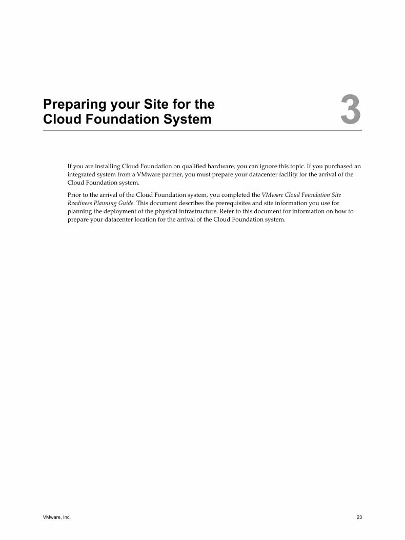
Preparing your Site for theCloud Foundation System 3
If you are installing Cloud Foundation on qualified hardware, you can ignore this topic. If you purchased anintegrated system from a VMware partner, you must prepare your datacenter facility for the arrival of theCloud Foundation system.
Prior to the arrival of the Cloud Foundation system, you completed the VMware Cloud Foundation SiteReadiness Planning Guide. This document describes the prerequisites and site information you use forplanning the deployment of the physical infrastructure. Refer to this document for information on how toprepare your datacenter location for the arrival of the Cloud Foundation system.
VMware, Inc. 23

VMware Cloud Foundation Overview and Bring-Up Guide
24 VMware, Inc.

Cloud Foundation Initial Bring-Up 4Once your physical rack is imaged (where the SDDC software is pre-configured on the rack), the rack ispowered on, and ToR switches are connected to the datacenter network, you connect a jump box to the ToRswitches and log in to the SDDC Manager using a browser on the jump box.
During power on, SDDC Manager completes the configuration of a private cloud in a process called bring-up.
The bring-up process involves multiple steps. Multi-rack configurations require all steps to be completed onthe first physical rack before adding additional physical racks
Prerequisites
Verify that you have met the following prerequisites.
n You have your completed copy of the VMware Cloud Foundation Site Readiness Planning Guide alongwith your VMware representative. This document contains networking and other information that youuse in the Cloud Foundation setup wizard.
n You have prepared your site, including power requirements, as described in the VMwareCloud Foundation Site Readiness Planning Guide.
n You have physical connectivity to the management switch in the first physical rack and a supportedweb browser such as Mozilla Firefox and Google Chrome. For the list of supported browser versions,see the Release Notes. To run the setup wizard, the browser must be able to connect to port 48 on a rack'smanagement switch. Some methods to accomplish this prerequisite are:
n On the physical rack, wire the management switch's port #48 to a computer (jump host) that hasone of the supported browsers, such as a Windows laptop with its integrated monitor.
n To use a browser on a remote computer, use a switch to connect the management switch's port #48to a network that your remote computer can use to access the port.
n If your physical rack has 4 nodes, set the value of the parameter rack.initial.mgmt.host=3.
a SSH to the SDDC Manager VM (192.168.100.40).
b Navigate to /home/vrack/VMware/vRack/vrm.properties.
c Set rack.initial.mgmt.host=3.
d Navigate to /home/vrack/vrm/webapps/vrm-ui/WEB-INF/classes/vrm.properties.
e Set rack.initial.mgmt.host=3.
f Restart the vrm-tcserver service.
service vrm-tcserver stop
service vrm-tcserver start
VMware, Inc. 25

Procedure
1 Connect Rack 1 to Your Power Source and Network on page 26
2 Initiate the Cloud Foundation Bring-Up Process on Rack 1 on page 27You initiate the bring-up process on a computer that can access the management switch in the physicalrack. The wizard runs in a standard web browser, such as Mozilla Firefox and Google Chrome. Afteryou provide site specific information such as rack name, passwords, IP addresses, and DNS and NTPdetails, SDDC Manager configures your private cloud.
3 Locate SDDC Manager IP Address on page 46The SDDC Manager IP address changes during bring-up. You need to look up the new IP address sothat you can log in to change the password on the rack components.
4 Change Passwords of Rack Components on page 47Cloud Foundation is deployed with factory default passwords. You must replace the defaultpasswords with secure system generated passwords.
5 Change SDDC Manager Password on page 48If you purchased an integrated system, your hardware partner sends you the system generatedpassword for SDDC Manager along with the imaged rack. If you deployed Cloud Foundation on aready system, you must have saved the SDDC Manager password. This password is not changedduring password rotation. VMware strongly recommends that you change this password beforecreating workloads.
6 Copy Backup File to an Accessible Location on page 49
Connect Rack 1 to Your Power Source and Network
Procedure
1 Connect the rack's power inlets to your power source.
2 Connect port 48 of rack 1's management switch to a laptop that has a standard web browser installed,from where you will run the setup wizard.
3 Configure the NIC on the laptop to tag VLAN traffic.
4 Create two interfaces on the laptop - say interfaces 1 and 2.
a Leave interface 1 untagged and assign the 192.168.100.248/24 IP address/subnet mask to it.
Interface 1 will allow OOB access to all Cloud Foundation hardware and software components.
b Tag interface 2 with the management VLAN and assign an unused IP address/subnet mask fromthe management network IPaddress pool used for management workload domains.
Interface 2 will allow for OOB access if there is an uplink mis-configuration and the system isunreachable from the upstream customer network.
5 Install a vSphere client application on the jump host.
Your Cloud Foundation system arrives with virtual machines pre-installed on ESX host 192.168.100.50in the rack. If any of those virtual machines do not power on when you power on the servers in a rack,you can use the vSphere Client application to connect to and manually power on the virtual machine.
What to do next
1 Ping host 0 at 192.168.100.50. If you are unable to ping host 0, contact VMware support.
VMware Cloud Foundation Overview and Bring-Up Guide
26 VMware, Inc.

2 Open a supported browser on the jump host and navigate to https://192.168.100.40:8443/vrm-ui. For alist of the supported browser versions, see the product Cloud Foundation Release Notes. If the browserdoes not display the setup wizard, the required virtual machines might not be powered on. Verifywhether the required virtual machines are running and, if not, power them on as described in “Manually Power On SDDC Manager VM When Setting Up Your Cloud Foundation System,” onpage 67.
Continue with the steps in “Initiate the Cloud Foundation Bring-Up Process on Rack 1,” on page 27.
Initiate the Cloud Foundation Bring-Up Process on Rack 1You initiate the bring-up process on a computer that can access the management switch in the physical rack.The wizard runs in a standard web browser, such as Mozilla Firefox and Google Chrome. After you providesite specific information such as rack name, passwords, IP addresses, and DNS and NTP details, SDDCManager configures your private cloud.
If you accidentally log out of the browser while the configuration process is running, the process continuesto progress. You can log back in to continue the configuration.
Prerequisites
1 Ensure that you have completed the steps in “Connect Rack 1 to Your Power Source and Network,” onpage 26.
2 Either turn off firewall on the jump host or ensure that the firewall ports required to accessCloud Foundation on it are open.
Table 4‑1. Inbound Ports for Cloud Foundation
Port Required for
TCP 8443 SDDC Manager
TCP/UDP 53 DNS resolution to SDDC Manager
TCP 22 (optional) SSH access to Cloud Foundation and vSphere components
Table 4‑2. Outbound Ports for Cloud Foundation
Port Required for
TCP/UDP 53 Corporate DNS resolution
UDP 123 NTP access to corporate time servers
In addition, VMware software may require additional firewall ports to be open.
n vRealize Operations
https://pubs.vmware.com/vrealizeoperationsmanager-6/index.jsp?topic=%2Fcom.vmware.vcom.core.doc%2FGUID-8CEB26FB-9EAF-45D7-A6A5-232A3CED3D6E.html
n vRealize Log Insight
https://pubs.vmware.com/log-insight-30/index.jsp?topic=%2Fcom.vmware.log-insight.security.doc%2FGUID-14DBC90A-379A-4316-9D76-4850E08437A8.html
n vCenter Server and ESXi
https://kb.vmware.com/selfservice/microsites/search.do?language=en_US&cmd=displayKC&externalId=1005189
n VMware Horizon with View
https://kb.vmware.com/selfservice/microsites/search.do?language=en_US&cmd=displayKC&externalId=1027217
Chapter 4 Cloud Foundation Initial Bring-Up
VMware, Inc. 27

n Platform Services Controller
https://pubs.vmware.com/vsphere-60/index.jsp?topic=%2Fcom.vmware.vsphere.upgrade.doc%2FGUID-925370DD-E3D1-455B-81C7-CB28AAF20617.html
3 Depending on the switches in your environment, ensure that two 40 Gbps ports or multiple 10 Gbpsports are connected to your corporate network and configured appropriately. For details, see VIA User'sGuide.
4 If your rack has only 4 ports, you must update the vrm.properties file before starting bring-up on therack.
a In a command line window, SSH to the base IP address for SDDC Manager on the rack.
b In the /home/vrack/VMware/vRack/vrm.properties file, change the rack.initial.mgmt.hosts=3parameter to rack.initial.mgmt.hosts=4 .
c In the /home/vrack/vrm/webapps/vrm-ui/web-inf/classes/vrm.properties file, change therack.initial.mgmt.hosts=3 parameter to rack.initial.mgmt.hosts=4 .
Procedure
1 After you connect the Cloud Foundation system to your network, wait at least 10 minutes beforeproceeding to the next step. This ensures that all rack components are powered on.
2 In a web browser on the laptop that you have connected to port #48 of the rack's management switch,navigate to https://192.168.100.40:8443/vrm-ui.
The Welcome page appears.
VMware Cloud Foundation Overview and Bring-Up Guide
28 VMware, Inc.

3 Click SET TIME.
The System Time for VMware Cloud Foundation page appears.
Chapter 4 Cloud Foundation Initial Bring-Up
VMware, Inc. 29

4 Specify the date, time, and time zone for the rack and click Submit. The specified time should match thecurrent time in your environment.
All the physical components in the environment are synchronised. After the time has been set on allCloud Foundation components, the SDDC Manager ISVMs are rebooted and the CONTINUE buttonturns blue.
5 Click CONTINUE.
The system performs Power On Self Validation (POSV), where it verifies that all the physicalcomponents are operational. This includes verifying that everything in the inventory is present, thehardware is healthy, and ensuring that the necessary services are running.
VMware Cloud Foundation Overview and Bring-Up Guide
30 VMware, Inc.

If the validation page displays an error, ensure that all physical connections are in place. Then clickRETRY.
Chapter 4 Cloud Foundation Initial Bring-Up
VMware, Inc. 31

6 After the validation is complete, click CONTINUE.
The Login page appears.
7 Type the default credentials:
User name: [email protected]
Password: vmware123
8 Click LOGIN.
The Cloud Foundation End User License Agreement (EULA) page appears.
9 Click AGREE.
The Create a Superuser Account page appears.
10 Type a user name and password for the superuser.
The password must be between 8 and 20 characters long and must contain at least one each of thefollowing:
n lowercase letter
n uppercase letter
n number
n special character such as ! or @
VMware Cloud Foundation Overview and Bring-Up Guide
32 VMware, Inc.

The superuser account has the same privileges as the [email protected] account. After thebring-up process is complete, the password for the [email protected] account is rotated to arandom password, but the password for the superuser account does not change. You can, thus, login toSDDC Manager with the superuser user name and password without having to look up the rotatedpassword for the administrator account.
11 Click CREATE SUPERUSER.
The Initial Setup wizard appears.
12 On the General information page, enter the following information.
Field Name Description
vRack Name Name of the virtual rack
Company Name Your company name
CompanyDepartment
Your department name
Root Domain Type your root DNS domain (for example, vmware.corp). This should be the same as theActive Directory domain.
VMware CloudFoundation SubDomain
Cloud Foundation generates this based on the root domain you specified. For example, ifyou specified the root domain as mycompany.example, the subdomain is auto-populated assubdomain.mycompany.example. You can edit this field.The sub domain is used for all components in Cloud Foundation. So everything is namedcomponent.subdomain. Based on our example, the NSX VM would be named rack-1-nsxmanager-1.subdomain.vmware.com.
SSO Domain Type the authentication domain to be used by SSO. For example, vsphere.local.The root domain and PSC domain must be different if you plan to join Active Directory. Ifyou will not join Active Directory, they can be the same.
Chapter 4 Cloud Foundation Initial Bring-Up
VMware, Inc. 33

Field Name Description
VMware CloudFoundation LicenseKey
Type the license key for Cloud Foundation. If you do not have the license key now, you canenter it later on the Cloud Foundation dashboard.
Joining Active Directory during Cloud Foundation bring-up can fail because of unconfigured or mis-configured uplinks, mis-configured upstream firewall, or incorrect corporate DNS configuration. Afterbring-up, you must identify and correct the cause of the failure. You can then manually connect eachPSC to Active Directory. See ESXi and vCenter Server 6.0 Documentation.
13 Click NEXT.
The Management Configuration page appears. You now provide network information such as theVLAN identifier and IP subnets for the management, vMotion, Virtual SAN, and VXLAN networks.The VLAN IDs you specify here are pre-configured on the physical switch infrastructure.
The following VLANs are configured while setting up networks for the bring-up phase:
a management
VMware Cloud Foundation Overview and Bring-Up Guide
34 VMware, Inc.

b vMotion
c vSAN
d VXLAN
e datacenter (corporate) network
The management and datacenter upstream networks are routable to the datacenter. The vMotion,VSAN, and VXLAN networks are routable only within Cloud Foundation.
Note that there is a progress bar at the top of the page. To make any changes to a previous screen, clickthe appropriate page title. After making a change, you must click NEXT for the change to take effect.
14 On the Management page, enter your management network values. The DNS server here is the DNS
server for your management network.
Field Name Description
VLAN ID The supported VLAN range is 3-3299.
Subnet VMware recommends using a /22 network. This is to allow for adequate IP addresscapacity as you expand your Cloud Foundation deployment by adding racks.
Subnet Mask VMware recommends using a /22 network.
Gateway Gateway address.
DNS DNS of your datacenter.
NTP NTP of your datacenter.
Exclude Individual IPAddresses
Enter a set of IP addresses to exclude from the provisioning process. For example, you canexclude those IP addresses that are already assigned to your network availability servicessuch as HSRP.To add multiple addresses, type an IP address, click the + sign, and type the next IPaddress.
Exclude IP AddressRanges
Enter a set of IP address ranges to exclude from the provisioning process. For example, youcan exclude a range of IP addresses that you want reserved for other uses in your network.To add multiple address ranges, type an IP address range, click the + sign, and type thenext IP address range.
15 Click USE DEFAULTS to allow Cloud Foundation to specify system generated IP address ranges forvMOTION, vSAN, and VXLAN. Since the Cloud Foundation network is an enclosed ecosystem, it isrecommended that you select this option.
Chapter 4 Cloud Foundation Initial Bring-Up
VMware, Inc. 35

16 Click NEXT.
The progress bar is displayed with additional wizard steps.
To make any changes to a previous screen, click the appropriate page title. After making a change, youmust click NEXT for the change to take effect.
17 On the vMotion Configuration page, review or enter your network addresses for VLAN ID, Subnet,Subnet Mask, Gateway, and excluded IP addresses and IP address ranges.
Note The supported VLAN range is 3-3299. VMware recommends using a /22 network for the subnetand subnet mask. This is to allow for adequate IP address capacity as you expand yourCloud Foundation deployment by adding racks.
VMware Cloud Foundation Overview and Bring-Up Guide
36 VMware, Inc.

18 Click NEXT.
The VSAN information page appears.
19 On the VSAN Information page, review or enter your Virtual SAN network addresses for the VLAN,Subnet, Subnet Mask, Gateway, and excluded IP addresses and IP address ranges..
Note The supported VLAN range is 3-3299. The subnet and subnet mask must be at least a /22network. This is to allow for adequate IP address capacity as you expand your Cloud Foundationdeployment by adding racks.
Chapter 4 Cloud Foundation Initial Bring-Up
VMware, Inc. 37
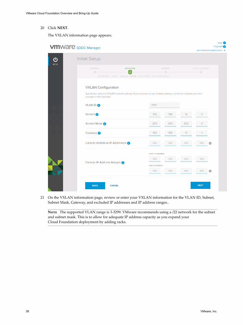
20 Click NEXT.
The VXLAN information page appears.
21 On the VXLAN information page, review or enter your VXLAN information for the VLAN ID, Subnet,Subnet Mask, Gateway, and excluded IP addresses and IP address ranges..
Note The supported VLAN range is 3-3299. VMware recommends using a /22 network for the subnetand subnet mask. This is to allow for adequate IP address capacity as you expand yourCloud Foundation deployment by adding racks.
VMware Cloud Foundation Overview and Bring-Up Guide
38 VMware, Inc.

22 Click NEXT.
The Data Center connections page appears.
Chapter 4 Cloud Foundation Initial Bring-Up
VMware, Inc. 39

23 The Data Center Connections page contains information for Cloud Foundation to connect to yourcorporate network. Enter your corporate network information for the VLAN ID, Connection Name,Network Start IP, Subnet Mask, Gateway, DNS, NTP, and excluded IP addresses and IP address ranges.
Important Review these values carefully before clicking NEXT because external connections are notvalidated at this time.
The Data Center Uplink page appears.
24 If the uplink is an L2 connection, provide the following information.
Field Description
Uplink Type L2
Uplink LAG Enabled It is recommended that you select this option.
Uplink Ports Port numbers on the ToR switches that are connected tothe uplink network.
Uplink Speed Speed for uplink connections.
25 If the uplink is an L3 connection, provide the following information.
Field Description
Uplink Type L3
Uplink LAG Enabled It is recommended that you select this option.
Uplink Ports Port numbers on the ToR switches that are connected tothe uplink network.
Uplink Speed Speed for uplink connections.
Uplink IP IP address of the uplink IP on the ToR switches.
VMware Cloud Foundation Overview and Bring-Up Guide
40 VMware, Inc.

Field Description
Mask IP Subnet mask for the uplink IP.
Next Hop IP IP address of the uplink switch for the data center.
Ensure that the management and external VLANs from Cloud Foundation are routable upstream.
For an L3 uplink, SDDC Manager configures a Switched VLAN Interface (SVI) for each requestedVLAN and configures a static route between ToR 1 and the upstream router. The configured SVI andthe configuration between the ToR and router is non-HA.
It is recommended that you set up iBGP between the ToR switches and an eBGP between each ToRswitch and the upstream router. This not automated. For information on the required configuration, see Chapter 9, “Example ToR Switch Output for L3 Configuration on Cisco ToR Switches (9372),” onpage 73.
Figure 4‑1. L3 Configuration
iBGP
eBGP
ECMP ECMP
eBGP
vPC
Router - 01ASN 64512
Router - 02ASN 64512
iBGP
ToR - 01ASN 64990
ToR - 02ASN 64990
Chapter 4 Cloud Foundation Initial Bring-Up
VMware, Inc. 41

26 Click NEXT.
The Configuration Review page appears.
VMware Cloud Foundation Overview and Bring-Up Guide
42 VMware, Inc.

27 On the Configuration Review page, review the information carefully.
28 After you ensure that all values on the Review page are accurate, click NEXT.
After a few moments, the Component IP Allocation page appears and displays the IP addresses for theVMs that will be deployed for the vRealize Log Insight, NSX, Platform Services Controller, SDDCManager, vCenter Server, and vRealize Operations software components.
If you need to make any change on the IP Reallocation page, click CANCEL to make edits as required.
29 Note down the virtual machine IP addresses. You will need these later in the bring-up process.
30 After you ensure that the IP Reallocation values are correct, click CONFIRM.
The Cloud Foundation configuration process begins. The amount of time it takes for the bring upprocess to be completed depends on the number of servers in the physical rack. The average time isapproximately 90 minutes.
Chapter 4 Cloud Foundation Initial Bring-Up
VMware, Inc. 43

You can see progress on the individual tasks by clicking Task Details.
VMware Cloud Foundation Overview and Bring-Up Guide
44 VMware, Inc.

Expand the task by clicking the blue arrow to see additional information. You can filter the tasks bystatus or time.
If there is an error during the configuration of the system, an error page appears. Click RETRY. Theconfiguration process remembers where it was in the sequence and start over from that point. If anerror occurs even after you rerun, contact VMware Support.
After the system configuration is completed, the SDDC Manager is restarted and the login screen isdisplayed.
31 Login with your superuser credentials . When SDDC Manager comes up, the Password Rotation page isdisplayed. For information on rotating the system passwords, see “Change Passwords of RackComponents,” on page 47
The Continue to Dashboard button is grayed out till password rotation is completed.
Chapter 4 Cloud Foundation Initial Bring-Up
VMware, Inc. 45

32 Note the IP address on the URL. If you accidentally close the browser, you will need this IP address tonavigate to the Dashboard.
33 Leave this browser window open.
34 Configure DNS delegation for automatic resolution of all names in Cloud Foundation.
SDDC Manager uses Unbound a DNS server software) for name resolution during theCloud Foundation bring-up. You must now configure the corporate DNS server to delegate zonecontrol for the Cloud Foundation domain to SDDC Manager.
For example, if your corporate domain is mycompany.example, and the Cloud Foundation Sub Domainis subdomain. mycompany.example, the corporate DNS server must be configured to delegate controlof subdomain. mycompany.example to SDDC Manager.
a Install DNS on your server by adding a new role through Server Manager and selecting DNS.
b Ensure that your jump server uses the local DNS for name resolution.
c Configure the primary zone (mycompany.example) as a zone managed by Windows DNS.
d Right-click the zone and select New Delegation.
e Enter the name of the sub-domain (subdomain).
f In the Server fully qualified domain name (FQDN) field, type the IP address of SDDC Managerand click Resolve.
g Click OK.
The new zone appears as a delegated zone under your primary domain.
h In a command line window, ping psc.Cloud_Foundation_Sub_Domain (psc.subdomain.mycompany.example in our example).
Locate SDDC Manager IP AddressThe SDDC Manager IP address changes during bring-up. You need to look up the new IP address so thatyou can log in to change the password on the rack components.
Procedure
1 Look up the vCenter Server IP address from the notes you took when the Component IP Allocationpage of the Initial Setup wizard displayed the IP addresses allocated to the virtual machines.
2 Login to this IP address via the vSphere Web Client. Use your superuser account credentials for the username and password. Append @vsphere.local to the user name.
3 Navigate to the Hosts and Clusters view and click the SDDC Manager VM in the left pane. The name ofthe VM appears as vrm-UUID.
4 On the right pane, click the Summary tab.
VMware Cloud Foundation Overview and Bring-Up Guide
46 VMware, Inc.

5 The IP Address field displays the SDDC Manager IP address.
\
6 Click View all to display all the IP addresses.
7 Identify the base IP addresses for SDDC Manager.
There are three IP addresses displayed for SDDC Manager. The IP address that was displayed for VRMon the IP Allocation page is the virtual IP (VIP) of the SDDC Manager. The other two IP addresses arethe base addresses. The private IP address is the 192.168.100.x. You need a base IP address for passwordrotation because the VIP disappears when the vrm-tcserver service is shut down, which will make youlose connectivity when you shut down the service as required during password rotation.
Change Passwords of Rack ComponentsCloud Foundation is deployed with factory default passwords. You must replace the default passwordswith secure system generated passwords.
Note In a multi-rack setup, you must change the passwords on the first physical rack before bringing-upadditional racks.
Prerequisites
You must have completed bring-up on the rack and the Password Rotation blocker screen must have beendisplayed.
Procedure
1 In a command line window, SSH to one of the base IP addresses for SDDC Manager on the rack. See “Locate SDDC Manager IP Address,” on page 46.
2 Navigate to /home/vrack/bin.
3 Type the following command:
./vrm-cli.sh lookup-password
The output displays the passwords and IP addresses for all components.
4 Save the output to a secure location so that you can access it later.
Chapter 4 Cloud Foundation Initial Bring-Up
VMware, Inc. 47

5 Save a copy of the /home/vrack/Vmware/vRack/vrm.properties file to a secure location where you canaccess it later.
6 In the SDDC Manager console window, navigate to /home/vrack/bin.
7 Type the following command:
./vrm-cli.sh rotate-all
This command changes the passwords of physical and logical components on the rack. Wait for 10minutes before proceeding to the next step.
8 In the SDDC Manager console window, type the following command again:
./vrm-cli.sh lookup-password
Save the output. Compare the output file you saved in step 5 with the output file you saved now andensure that all passwords have been changed. Note the password for the administrator account, whichyou will need for logging in to the Cloud Foundation dashboard.
9 Refresh the browser window where you were running the Initial Setup wizard.
The Continue to Dashboard button is now green. Click this button to display the Cloud FoundationDashboard.
10 Log out of the Dashboard.
11 Log back in using your superuser credentials.
Change SDDC Manager PasswordIf you purchased an integrated system, your hardware partner sends you the system generated passwordfor SDDC Manager along with the imaged rack. If you deployed Cloud Foundation on a ready system, youmust have saved the SDDC Manager password. This password is not changed during password rotation.VMware strongly recommends that you change this password before creating workloads.
Procedure
1 In a command line window, SSH to the SDDC Manager on the rack.
2 Login as root. Use the password provided to you by the partner (integrated system use case) or the oneyou saved after imaging the rack(ready system deployment use case.
3 Type the following command to change the password:
passwd
4 At the prompt, type and re-type the new password.
The SDDC Manager password is changed.
5 Refresh the web browser window where you were running the Initial Setup wizard.
6 Type in one of the following set of credentials:
n superuser account username and password that you created during the initial setup
n [email protected] user name and the password you noted down afer rotating it(credentials appear in the Single Sign On section in the output of the lookup-password command)
The dashboard page appears.
VMware Cloud Foundation Overview and Bring-Up Guide
48 VMware, Inc.
For information on how to administer and operate your data center's Cloud Foundation system, see theAdministering VMware Cloud Foundation.
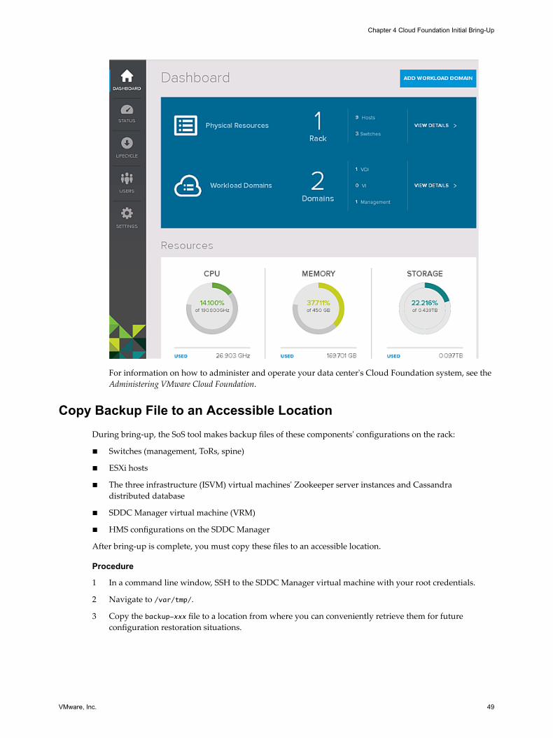
Copy Backup File to an Accessible LocationDuring bring-up, the SoS tool makes backup files of these components' configurations on the rack:
n Switches (management, ToRs, spine)
n ESXi hosts
n The three infrastructure (ISVM) virtual machines' Zookeeper server instances and Cassandradistributed database
n SDDC Manager virtual machine (VRM)
n HMS configurations on the SDDC Manager
After bring-up is complete, you must copy these files to an accessible location.
Procedure
1 In a command line window, SSH to the SDDC Manager virtual machine with your root credentials.
2 Navigate to /var/tmp/.
3 Copy the backup-xxx file to a location from where you can conveniently retrieve them for futureconfiguration restoration situations.
Chapter 4 Cloud Foundation Initial Bring-Up
VMware, Inc. 49

VMware Cloud Foundation Overview and Bring-Up Guide
50 VMware, Inc.

Adding Racks to yourCloud Foundation System 5
Once Cloud Foundation is running on the first physical rack, you can bring up Cloud Foundation onadditional physical racks in your environment
Note The SDDC Manager version on the rack you want to add must match the version of the other racks inyour environment. If the new rack is a later version, you must upgrade the other racks in your environmentbefore you add it to your Cloud Foundation system.
Procedure
1 Connect Rack 2 to Spine Switches on page 51This procedure refers to the rack being added as rack 2. Follow the same procedure for adding anyrack.
2 Power on Rack 2 on page 52After the spine connections are in place, you can power on rack 2.
3 Bootstrap Additional Rack on page 52Bootstrap SDDC Manager on rack 2 from SDDC Manager on rack 1.
4 Manual Steps for Rack Addition on page 55Complete these steps before bringing-up the additional rack.
5 Initiate the Bring-Up Process on Additional Rack on page 56Complete bring-up on the rack you are adding to your Cloud Foundation system.
6 Changing Passwords of Rack Components on page 61Cloud Foundation is deployed with factory default passwords. It is highly recommended that youreplace the default passwords with secure system generated passwords.
7 Change SDDC Manager Password on Each Additional Rack on page 61If you purchased an integrated system, your hardware partner sends you the system generatedpassword for SDDC Manager along with the imaged rack. If you deployed Cloud Foundation on aready system, you must have saved the SDDC Manager password. During password rotation, theSDDC Manager is not changed. VMware strongly recommends that you change this password on eachrack before creating workloads.
Connect Rack 2 to Spine SwitchesThis procedure refers to the rack being added as rack 2. Follow the same procedure for adding any rack.
Prerequisites
1 Ensure that rack 2 is powered down so that there is no connectivity between rack 1 and rack 2.
VMware, Inc. 51

2 The bring-up process must have been completed successfully on rack 1. Rack 1 Dashboard must beaccessible and the SDDC Manager VM (VRM) on rack 1 must be powered on.
3 Password rotation must have been completed on rack 1.
Procedure
1 Make the following connections:
n Rack 1 ToR 1 port 49 to spine 1 port 1 on rack 2
n Rack 1 ToR 1 port 50 to spine 2 port 1 on rack 2
n Rack 1 ToR 2 port 49 to spine 1 port 2 on rack 2
n Rack 1 ToR 2 port 50 to spine 2 port 2 on rack 2
2 While rack 2 is still powered down, verify that the ports on the spine switches on rack 2 are up.
3 Verify that the link connectivity LED between the racks is up.
What to do next
Power on rack 2.
Power on Rack 2After the spine connections are in place, you can power on rack 2.
Procedure
1 Power on rack 2.
2 Ensure that you can ping SDDC Manager on rack 2 from rack 1.
a SSH to SDDC Manager on rack 1 with your superuser account credentials.
b Ping SDDC Manager on rack 2 (192.168.100.40).
What to do next
Bootstrap additional rack.
Bootstrap Additional RackBootstrap SDDC Manager on rack 2 from SDDC Manager on rack 1.
Procedure
1 On the SDDC Manager Dashboard for rack 1, click SETTINGS > Physical Rack Settings.
VMware Cloud Foundation Overview and Bring-Up Guide
52 VMware, Inc.

2 Click the Additional Rack tab.
The thumbprint of rack 2 is displayed here.
3 Click ADD RACK.
The Add a Rack wizard appears.
4 Compare the thumbprint displayed on the screen with the thumbprint you received from the partner(integrated system use case) or the thumbprint you saved after imaging the rack (ready system usecase).
Chapter 5 Adding Racks to your Cloud Foundation System
VMware, Inc. 53

5 If the thumbprints match, click CONFIRM.
The Validation page appears.
6 On the Validation page, type the bootstrap password and click CONFIRM.
The Confirmation page confirms that the additional rack has been added to the Cloud Foundationsystem.
VMware Cloud Foundation Overview and Bring-Up Guide
54 VMware, Inc.

7 Click DONE.
The Additional Rack page displays the thumbprint of the rack you just added. The CONFIGUREbutton is grayed out until you complete the manual steps required at this point. See “Manual Steps forRack Addition,” on page 55.
8 Leave this browser window open.
What to do next
Complete manual steps for rack addition.
Manual Steps for Rack AdditionComplete these steps before bringing-up the additional rack.
Procedure
1 Copy the file encryption keys from rack 1 to rack 2. This file will be used to perform encryption anddecryption while saving and retrieving the ESXi and PSC passwords to and from Zookeeper.
a In a command line window, SSH to the private IP address of SDDC Manager on rack 2.
For information on retrieving the private IP address of SDDC Manager, see “Locate SDDCManager IP Address,” on page 46.
b Run the following script:
/home/vrack/VMware/vRack/copycryptokeys.sh
The default source and destination paths are displayed.
c Type the password of the SDDC Manager on the first physical rack.
If the files are copied successfully, the message File copied successfully is displayed.
2 Confirm that the ISVMs on rack 2 are deleted.
3 Navigate to /home/vrack/bin.
4 Sync the SDDC Manager properties by typing the following command.
./vrm-cli.sh sync-properties
Chapter 5 Adding Racks to your Cloud Foundation System
VMware, Inc. 55

Initiate the Bring-Up Process on Additional RackComplete bring-up on the rack you are adding to your Cloud Foundation system.
Procedure
1 Do one of the following to begin bring-up:
n In the Add a Rack wizard that you had left after bootstrapping the additional rack, clickCONFIGURE.
n Open a new browser window and type the following URL:
https://192.168.100.40:8443/vrm-ui
The Welcome page appears.
2 Click SET TIME.
The System Time for VMware Cloud Foundation page appears.
VMware Cloud Foundation Overview and Bring-Up Guide
56 VMware, Inc.

The date, time, and time zone are fetched from the first physical rack.
Chapter 5 Adding Racks to your Cloud Foundation System
VMware, Inc. 57

3 The system sets the time on each Cloud Foundation component in the additional rack.
After the time has been set on all Cloud Foundation components, SDDC Manager is rebooted and theCONTINUE button turns blue.
4 Click CONTINUE.
The system performs Power On System Validation (POSV), where it verifies that the integrated systemdelivered to the customer is correct and operational. It validates that the right hardware and software isinstalled in the racks and also validates the health of the installed hardware and software applications.
VMware Cloud Foundation Overview and Bring-Up Guide
58 VMware, Inc.
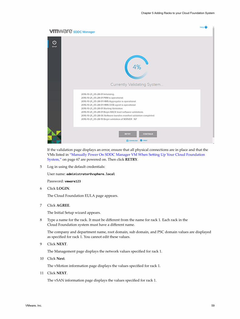
If the validation page displays an error, ensure that all physical connections are in place and that theVMs listed in “Manually Power On SDDC Manager VM When Setting Up Your Cloud FoundationSystem,” on page 67 are powered on. Then click RETRY.
5 Log in using the default credentials:
User name: [email protected]
Password: vmware123
6 Click LOGIN.
The Cloud Foundation EULA page appears.
7 Click AGREE.
The Initial Setup wizard appears.
8 Type a name for the rack. It must be different from the name for rack 1. Each rack in theCloud Foundation system must have a different name.
The company and department name, root domain, sub domain, and PSC domain values are displayedas specified for rack 1. You cannot edit these values.
9 Click NEXT.
The Management page displays the network values specified for rack 1.
10 Click Next.
The vMotion information page displays the values specified for rack 1.
11 Click NEXT.
The vSAN information page displays the values specified for rack 1.
Chapter 5 Adding Racks to your Cloud Foundation System
VMware, Inc. 59

12 Click NEXT.
The vXLAN information page displays the values specified for rack 1.
13 Click NEXT.
The Data Center Connections page displays the values specified for rack 1.
14 Click NEXT.
The Configuration Review page displays the values specified for rack 1.
15 Click NEXT.
The Review page appears.
16 Review the information.
17 Click CONNECT.
After a few minutes, the Component IP Allocation page appears and displays the IP addresses for theVMs that will be deployed for the NSX, SDDC Manager, vCenter Server, and vRealize Operationssoftware components. Ignore the Log Insight IP address. Log Insight is only deployed on rack 1.
18 After you ensure that the IP Reallocation values are correct, click CONFIRM.
The Configuring System page displays the task that is running and the list of tasks that need to becompleted. Click TASK DETAILS to view additional details for the tasks. Click next to the task to seefurther details. You can filter tasks by status (Running, Successful, or New) or time range.
In case a task fails, click RETRY to run the task again.
If restarting the Network: Configure VLAN Tags on Switches task fails, restart the tcserver on theadditional rack.
a SSH to the SDDC Manager VM on the additional rack.
b Type service vrm-tcserver stop.
c Type service vrm-tcserver start.
19 After the system configuration is completed, the SDDC Manager is restarted. When SDDC Managercomes up, the Password Rotation page is displayed.
20 Leave this browser window open.
21 Rotate passwords on rack 2. See “Change SDDC Manager Password on Each Additional Rack,” onpage 61.
You cannot access the SDDC Manager Dashboard on rack 1 till you complete this step.
22 If DNS delegation for automatic resolution is configured in your environment, you are redirected to thelogin page in the browser window you had left open. Log in using the superuser credentials or thesystem administrator account name (administrator@domainName) and password that you noted downafter password rotation. The Dashboard page appears. The Physical Resources on the Dashboardincludes both rack1 and rack 2.
VMware Cloud Foundation Overview and Bring-Up Guide
60 VMware, Inc.

Changing Passwords of Rack ComponentsCloud Foundation is deployed with factory default passwords. It is highly recommended that you replacethe default passwords with secure system generated passwords.
You must change the passwords on each rack that you add to your Cloud Foundation system.
Note The additional rack must have successfully completed bring-up before you change the passwords.
1 In a command line window, SSH to one of the base IP addresses for SDDC Manager on the rack. See “Locate SDDC Manager IP Address,” on page 46.
2 Navigate to /home/vrack/bin.
3 Type the following command:
./vrm-cli.sh lookup-password
The output displays the passwords and IP addresses for all components on rack 1.
4 Save the output to a secure location so that you can access it later.
5 Save a copy of the /home/vrack/VMware/vRack/vrm.properties file to a secure location where you canaccess it later.
6 In the SDDC Manager console window for rack 1, navigate to /home/vrack/bin.
7 Type the following command:
./vrm-cli.sh rotate-all
This command changes the passwords of the physical components on rack 1 and logical components onall racks in your environment.
8 In the SDDC Manager console window, type the following command:
./vrm-cli.sh lookup-password
Save the output. Compare the output file you saved in step 5 with the output file you saved now andensure that all passwords have been changed.
9 Refresh the browser window where you were running the Initial Setup wizard.
The Cloud Foundation Dashboard is displayed.
Change SDDC Manager Password on Each Additional RackIf you purchased an integrated system, your hardware partner sends you the system generated passwordfor SDDC Manager along with the imaged rack. If you deployed Cloud Foundation on a ready system, youmust have saved the SDDC Manager password. During password rotation, the SDDC Manager is notchanged. VMware strongly recommends that you change this password on each rack before creatingworkloads.
Procedure
1 In a command line window, SSH to the SDDC Manager on the rack.
2 Login as root. Use the password provided to you by the partner (integrated system use case) or the oneyou saved after imaging the rack (ready system deployment use case).
3 Type the following command to change the password:
passwd
Chapter 5 Adding Racks to your Cloud Foundation System
VMware, Inc. 61

4 At the prompt, type and re-type the new password.
The SDDC Manager password is changed.
VMware Cloud Foundation Overview and Bring-Up Guide
62 VMware, Inc.

Alerts List 6An alert is a record of a known detected problem. Alerts can be raised at Power On System Validation(POSV), at a set interval when the system polls the alert catalog, or when an event is generated. An event is arecord of a system condition that is potentially significant or interesting to you, such as a degradation,failure, or user-initiated configuration change.
Table 6‑1. Cloud Foundation Alerts
Alert Name Short DescriptionSeverityLevel
DetectedBy
BMC_AUTHENTICATION_FAILURE_ALERT The system is unable to authenticate tothe server's out-of-band (OOB)management port.
ERROR Event
BMC_MANAGEMENT_FAILURE_ALERT The system failed to perform amanagement operation using the server'sOOB management port.
ERROR Event
BMC_NOT_REACHABLE_ALERT The system is unable to communicatewith the BMC server's out-of-band (OOB)management port.
ERROR Event
COORDINATION_SERVICE_DOWN_ALERT Cannot establish connection withZookeeper.
ERROR
CPU_CAT_FAILURE_ALERT A processor has shut down due to acatastrophic error.
ERROR Event
CPU_EXTRA_ALERT Mismatch between CPU spec in manifestfile and physical CPU inventory reportedby HMS. An extra CPU is present in thephysical inventory.
WARNING Event
CPU_INITIALIZATION_ERROR_ALERT The system detected that a CPUinitialization error has occurred.
ERROR Event
CPU_INVALID_ALERT The polling detected a type of CPU in theserver that does not match what isexpected according to the manifest.
ERROR POSV andsystempoll
CPU_MACHINE_CHECK_ERROR_ALERT A server CPU has failed due to CPUMachine Check Error.
ERROR Event
CPU_POST_FAILURE_ALERT A server CPU has shut down due toPOST failure.
ERROR Event
CPU_TEMPERATURE_ABOVE_UPPER_THRESHOLD_ALERT
A CPU temperature has reached itsmaximum safe operating temperature.
WARNING Event
CPU_TEMPERATURE_BELOW_LOWER_THRESHOLD_ALERT
A CPU temperature has reached itsminimum safe operating temperature.
WARNING Event
VMware, Inc. 63

Table 6‑1. Cloud Foundation Alerts (Continued)
Alert Name Short DescriptionSeverityLevel
DetectedBy
CPU_THERMAL_TRIP_ERROR_ALERT A server CPU has shut down due tothermal error.
ERROR Yes
CPU_UNDETECTED_ALERT A CPU matching the manifest was notdetected.
ERROR Event
DIMM_ECC_MEMORY_ERROR_ALERT The system detected an uncorrectableError Correction Code (ECC) error for aserver's memory.
ERROR Event
DIMM_TEMPERATURE_ABOVE_THRESHOLD_ALERT
Memory temperature has reached itsmaximum safe operating temperature.
WARNING Event
DIMM_THERMAL_TRIP_ALERT Memory has shut down due to thermalerror.
ERROR Event
EVO_SDDC_BUNDLE_INCOMPLETE_ALERT The Cloud Foundation ISO file is missingsome elements.
CRITICAL POSV
EVO_SDDC_BUNDLE_INVALID_ALERT MD5 checksum generated on theCloud Foundation ISO bundle does notmatch the MD5 checksum provided byVIA in the vSAN datastore.
CRITICAL POSV
EVO_SDDC_BUNDLE_MISSING_ALERT The Cloud Foundation bundle ISO file orMD5checksum file is missing.
CRITICAL POSV
HDD_DOWN_ALERT Operational status is down for an HDD. ERROR Event
HDD_EXCESSIVE_READ_ERRORS_ALERT Excessive read errors reported for anHDD.
WARNING Event
HDD_EXCESSIVE_WRITE_ERRORS_ALERT Excessive write errors reported for anHDD
WARNING Event
HDD_EXTRA_ALERT Additional HDD detected that does notmatch the manifest.
WARNING POSV andsystempoll
HDD_INVALID_ALERT Detected HDD does not match themanifest.
ERROR POSV andsystempoll
HDD_TEMPERATURE_ABOVE_THRESHOLD_ALERT
HDD temperature has reached itsmaximum safe operating temperature.
WARNING Event
HDD_UNDETECTED_ALERT HDD matching the manifest was notdetected.
ERROR POSV andsystempoll
HDD_WEAROUT_ABOVE_THRESHOLD_ALERT
Wear-out state of an HDD is above itsdefined threshold.
WARNING Event
HMS_AGENT_DOWN_ALERT A physical rack's Hardware ManagementServices agent is down.
CRITICAL POSV
HMS_DOWN_ALERT The HMS is down. CRITICAL POSV andevent
HOST_AGENT_NOT_ALIVE_ALERT ESXi on a server in a physical rack is notrunning.
POSV
MANAGEMENT_SWITCH_DOWN_ALERT Operational status is down for a physicalrack's management switch.
WARNING POSV,systempoll, andevent
VMware Cloud Foundation Overview and Bring-Up Guide
64 VMware, Inc.

Table 6‑1. Cloud Foundation Alerts (Continued)
Alert Name Short DescriptionSeverityLevel
DetectedBy
MANAGEMENT_SWITCH_EXTRA_ALERT Additional management switch detectedthat does not match the manifest.
WARNING POSV,systempoll, andevent
MANAGEMENT_SWITCH_INVALID_ALERT Detected management switch does notmatch the manifest.
CRITICAL POSV,systempoll, andevent
MANAGEMENT_SWITCH_PORT_DOWN_ALERT
Operational status is down for a port in aphysical rack's management switch.
WARNING Event
MEMORY_EXTRA_ALERT Detected additional memory that doesnot match the manifest.
WARNING POSV andsystempoll
MEMORY_INVALID_ALERT Detected memory type does not matchmanifest.
ERROR POSV andsystempoll
MEMORY_UNDETECTED_ALERT Memory matching the manifest was notdetected.
ERROR POSV andsystempoll
PCH_TEMPERATURE_ABOVE_THRESHOLD_ALERT
Platform controller hub (PCH)temperature has reached its maximumsafe operating temperature.
WARNING Event
SERVER_DOWN_ALERT Server is in the powered-down state. ERROR POSV andsystempoll
SERVER_EXTRA_ALERT Detected additional server that does notmatch the manifest.
WARNING POSV andsystempoll
SERVER_INVALID_ALERT Detected server does not match themanifest.
ERROR POSV andsystempoll
SERVER_PCIE_ERROR_ALERT A server's system has PCIe errors. ERROR Event
SERVER_POST_ERROR_ALERT A server has POST failures ERROR Event
SERVER_UNDETECTED_ALERT Server matching the manifest as notdetected.
ERROR POSV andsystempoll
SPINE_SWITCH_DOWN_ALERT Operational status is down for a physicalrack's spine switch.
ERROR POSV,systempoll, andevent
SPINE_SWITCH_EXTRA_ALERT Detected spine switch does not match themanifest.
WARNING POSV andsystempoll
SPINE_SWITCH_INVALID_ALERT Detected spine switch does not match themanifest.
ERROR POSV andsystempoll
SPINE_SWITCH_PORT_DOWN_ALERT Operational status is down for a port: ina physical rack's spine switch.
WARNING Event
SSD_DOWN_ALERT Operational status is down for an SSD. ERROR Event
Chapter 6 Alerts List
VMware, Inc. 65

Table 6‑1. Cloud Foundation Alerts (Continued)
Alert Name Short DescriptionSeverityLevel
DetectedBy
SSD_EXCESSIVE_READ_ERRORS_ALERT Excessive read errors reported for anSSD.
WARNING Event
SSD_EXCESSIVE_WRITE_ERRORS_ALERT Excessive write errors reported for anSSD.
WARNING Event
SSD_EXTRA_ALERT Detected additional SSD that does notmatch the manifest.
WARNING POSV andsystempoll
SSD_INVALID_ALERT Detected SSD does not match themanifest.
ERROR POSV andsystempoll
SSD_TEMPERATURE_ABOVE_THRESHOLD_ALERT
SSD temperature has reached itsmaximum safe operating temperature
WARNING Event
SSD_UNDETECTED_ALERT SSD matching the manifest was notdetected.
ERROR POSV andsystempoll
SSD_WEAROUT_ABOVE_THRESHOLD_ALERT
Wear-out state of an SSD is above itsdefined threshold.
WARNING Event
STORAGE_CONTROLLER_DOWN_ALERT Operational status is down for a storageadapter.
ERROR Event
TOR_SWITCH_DOWN_ALERT Operational status is down for a physicalrack's ToR switch.
ERROR POSV andsystempoll
TOR_SWITCH_EXTRA_ALERT Detected extra ToR switch that does notmatch the manifest.
WARNING POSV andsystempoll
TOR_SWITCH_INVALID_ALERT Detected ToR switch does not match themanifest.
ERROR POSV andsystempoll
TOR_SWITCH_PORT_DOWN_ALERT Operational status is down for a port in aphysical rack's ToR switch.
WARNING Event
VMware Cloud Foundation Overview and Bring-Up Guide
66 VMware, Inc.

Troubleshooting Cloud FoundationDeployment 7
You can troubleshoot issues that you might experience during deployment of your Cloud Foundationsystem.
This chapter includes the following topics:
n “Manually Power On SDDC Manager VM When Setting Up Your Cloud Foundation System,” onpage 67
n “Restart HMS,” on page 68
n “Retry If Bring-Up Fails During NFS Datastore Creation,” on page 68
n “Retry If Bring-Up Fails During NSX Power Up,” on page 68
Manually Power On SDDC Manager VM When Setting Up YourCloud Foundation System
When you power on a rack, the SDDC Manager VM (VRM) that is pre-installed on host 0 is supposed topower on automatically. If this does not happen, you can manually power it on using the vSphere Clientapplication.
Problem
You open your browser to the address for the SDDC Manager setup wizard, and you do not see the wizard'sstarting screen. Instead of displaying the wizard, the browser shows there is no connection.
Cause
The setup wizard requires the pre-installed SDDC Manager VM to be running. If it is not powered on whenthe ESXi host powers on, the setup wizard cannot run.
Solution
1 On the jump host that is connected to port #48 on the management switch, start the vSphere Client andopen it to IP address 192.168.100.100.
2 Log in to the host.
3 In the vSphere Client, navigate to the Inventory view to see the vrm VM. Ensure that it is powered on. Ifa virtual machine does not have a green arrow icon, it is not powered on.
The LCM Repository and 3 Zookeeper VMs are also pre-installed. Once the vrm VM is powered on, itpowers on the 3 Zookeeper VMs. The LCM Repository VM is activated during the Cloud Foundationdeployment.
4 If vrm VM is not powered on, power it on.
VMware, Inc. 67

Restart HMSYou may need to restart HMS while deploying the Cloud Foundation system.
Problem
While deploying the Cloud Foundation system, the following error message is displayed:
vRack has encountered an error. Problem connecting with HMS host: http://localhost:8080/hms-
local at the moment.
Cause
HMS may have stopped running.
Solution
1 Verify if HMS is running by connecting to the management switch and typing the following commands:
jobs
ps –lef |grep -i hms
2 If HMS is not running, restart HMS by typing the following commands.
cd /opt/vrack/hms
service starthms.sh start
Retry If Bring-Up Fails During NFS Datastore CreationYou might experience an exception during the NFS datastore creation in the bring-up process.
Problem
If intermittent network connectivity occurs during the bring-up process, the process might fail during theESX: Create NFS Datastore task with the following exception:
Exception trying to create NAS DS on host host-ip-address
Cause
Intermittent network connectivity to an ESXi host during the bring-up process.
Solution
u In the bring-up user interface, click the Retry button to perform the task and proceed with the bring-upprocess.
Retry If Bring-Up Fails During NSX Power UpYou might experience an exception during the bring-up process if the NSX nodes fail to power on.
Problem
In a multi-rack system, a VI workload domain creation workflow might fail during the NSX: RegistervCenter task with an error stating that NSX did not power on.
Cause
The bring-up process fails because the NSX Controller virtual machines did not power on during the waittime set in the NSX: Register vCenter task.
VMware Cloud Foundation Overview and Bring-Up Guide
68 VMware, Inc.

Solution
u In the bring-up user interface, click the Retry button to perform the task and proceed with the bring-upprocess.
Chapter 7 Troubleshooting Cloud Foundation Deployment
VMware, Inc. 69

VMware Cloud Foundation Overview and Bring-Up Guide
70 VMware, Inc.

Additional VMware ProductDocumentation 8
Refer to the appropriate documentation for help with VMware SDDC products that are part ofCloud Foundation.
Product Name Documentation
VMware ESXi andvCenter Server
ESXi and vCenter Server 6.0 Documentation at http://pubs.vmware.com/vsphere-60/topic/com.vmware.ICbase/Welcome/welcome.html
vSAN Administering VMware Virtual SAN at http://pubs.vmware.com/vsphere-60/topic/com.vmware.ICbase/PDF/virtual-san-61-administration-guide.pdf
NSX NSX for vSphere Documentation at http://pubs.vmware.com/NSX-62/topic/com.vmware.ICbase/Welcome/welcome.html
vRealize Operations VMware vRealize Operations Manager Documentation at https://www.vmware.com/support/pubs/vrealize-operations-manager-pubs.html
vRealize Log Insight VMware vRealize Log Insight Documentation at http://pubs.vmware.com/log-insight-30/topic/com.vmware.ICbase/Welcome/welcome.html
VMware, Inc. 71

VMware Cloud Foundation Overview and Bring-Up Guide
72 VMware, Inc.

Example ToR Switch Output for L3Configuration on Cisco ToR Switches(9372) 9
Example ToR Switch Output when you set up an iBGP connection between the ToR switches and an eBGPbetween each ToR switch and the upstream router.
TOR-20(config)# show running-config bgp
!Command: show running-config bgp
!Time: Tue Nov 8 00:50:29 2016
version 7.0(3)I2(2d)
feature bgp
router bgp 64990
router-id 192.168.220.1
address-family ipv4 unicast
redistribute direct route-map rmap-bgp
maximum-paths 4
maximum-paths ibgp 2
neighbor 192.168.53.2
remote-as 64990
address-family ipv4 unicast
neighbor 192.168.54.2
remote-as 64990
address-family ipv4 unicast
neighbor 192.168.143.2
remote-as 64512
address-family ipv4 unicast
neighbor 192.168.144.2
remote-as 64512
address-family ipv4 unicast
neighbor 192.168.145.2
remote-as 64512
address-family ipv4 unicast
neighbor 192.168.146.2
remote-as 64512
address-family ipv4 unicast
TOR-20(config)# show ip interface brief
IP Interface Status for VRF "default"(1)
Interface IP Address Interface Status
Vlan1001 192.168.120.21 protocol-up/link-up/admin-up
Vlan1005 192.168.98.1 protocol-up/link-up/admin-up
VMware, Inc. 73

Lo0 192.168.220.1 protocol-up/link-up/admin-up
Eth1/43 192.168.143.1 protocol-up/link-up/admin-up
Eth1/44 192.168.144.1 protocol-up/link-up/admin-up
Eth1/45 192.168.145.1 protocol-up/link-up/admin-up
Eth1/46 192.168.146.1 protocol-up/link-up/admin-up
Eth1/53 192.168.53.1 protocol-up/link-up/admin-up
Eth1/54 192.168.54.1 protocol-up/link-up/admin-up
TOR-21(config)# show running-config bgp
!Command: show running-config bgp
!Time: Tue Nov 8 00:54:23 2016
version 7.0(3)I2(2d)
feature bgp
router bgp 64990
router-id 192.168.220.2
address-family ipv4 unicast
redistribute direct route-map rmap-bgp
maximum-paths 4
maximum-paths ibgp 2
neighbor 192.168.53.1
remote-as 64990
address-family ipv4 unicast
neighbor 192.168.54.1
remote-as 64990
address-family ipv4 unicast
neighbor 192.168.243.2
remote-as 64512
address-family ipv4 unicast
neighbor 192.168.244.2
remote-as 64512
address-family ipv4 unicast
neighbor 192.168.245.2
remote-as 64512
address-family ipv4 unicast
neighbor 192.168.246.2
remote-as 64512
address-family ipv4 unicast
TOR-21(config)# show ip interface brief
IP Interface Status for VRF "default"(1)
Interface IP Address Interface Status
Vlan1001 192.168.120.20 protocol-up/link-up/admin-up
Lo0 192.168.220.2 protocol-up/link-up/admin-up
Eth1/43 192.168.243.1 protocol-up/link-up/admin-up
Eth1/44 192.168.244.1 protocol-up/link-up/admin-up
Eth1/45 192.168.245.1 protocol-up/link-up/admin-up
Eth1/46 192.168.246.1 protocol-up/link-up/admin-up
Eth1/53 192.168.53.2 protocol-up/link-up/admin-up
Eth1/54 192.168.54.2 protocol-up/link-up/admin-up
VMware Cloud Foundation Overview and Bring-Up Guide
74 VMware, Inc.

Core1(config-router)# show running-config bgp
!Command: show running-config bgp
!Time: Tue Nov 8 00:57:53 2016
version 7.0(3)I4(2)
feature bgp
router bgp 64512
router-id 192.168.221.1
address-family ipv4 unicast
redistribute direct route-map rmap-bgp
maximum-paths 4
maximum-paths ibgp 2
neighbor 192.168.49.2
remote-as 64512
address-family ipv4 unicast
neighbor 192.168.50.2
remote-as 64512
address-family ipv4 unicast
neighbor 192.168.143.1
remote-as 64990
address-family ipv4 unicast
neighbor 192.168.144.1
remote-as 64990
address-family ipv4 unicast
neighbor 192.168.245.1
remote-as 64990
address-family ipv4 unicast
neighbor 192.168.246.1
remote-as 64990
address-family ipv4 unicast
Core1(config-router)# show ip interface brief
IP Interface Status for VRF "default"(1)
Interface IP Address Interface Status
Lo0 192.168.221.1 protocol-up/link-up/admin-up
Eth1/1 192.168.143.2 protocol-up/link-up/admin-up
Eth1/2 192.168.144.2 protocol-up/link-up/admin-up
Eth1/3 192.168.245.2 protocol-up/link-up/admin-up
Eth1/4 192.168.246.2 protocol-up/link-up/admin-up
Eth1/49 192.168.49.1 protocol-up/link-up/admin-up
Eth1/50 192.168.50.1 protocol-up/link-up/admin-up
Core2(config-router)# show running-config bgp
!Command: show running-config bgp
!Time: Tue Nov 8 00:58:04 2016
version 7.0(3)I4(2)
feature bgp
router bgp 64512
router-id 192.168.221.2
Chapter 9 Example ToR Switch Output for L3 Configuration on Cisco ToR Switches (9372)
VMware, Inc. 75

address-family ipv4 unicast
redistribute direct route-map rmap-bgp
maximum-paths 4
maximum-paths ibgp 2
neighbor 192.168.49.1
remote-as 64512
address-family ipv4 unicast
neighbor 192.168.50.1
remote-as 64512
address-family ipv4 unicast
neighbor 192.168.145.1
remote-as 64990
address-family ipv4 unicast
neighbor 192.168.146.1
remote-as 64990
address-family ipv4 unicast
neighbor 192.168.243.1
remote-as 64990
address-family ipv4 unicast
neighbor 192.168.244.1
remote-as 64990
address-family ipv4 unicast
Core2(config-router)# show ip interface brief
IP Interface Status for VRF "default"(1)
Interface IP Address Interface Status
Lo0 192.168.221.2 protocol-up/link-up/admin-up
Eth1/1 192.168.243.2 protocol-up/link-up/admin-up
Eth1/2 192.168.244.2 protocol-up/link-up/admin-up
Eth1/3 192.168.145.2 protocol-up/link-up/admin-up
Eth1/4 192.168.146.2 protocol-up/link-up/admin-up
Eth1/49 192.168.49.2 protocol-up/link-up/admin-up
Eth1/50 192.168.50.2 protocol-up/link-up/admin-up
VMware Cloud Foundation Overview and Bring-Up Guide
76 VMware, Inc.

Glossary 10Term Description
bring-up Initial configuration of a newly deployed Cloud Foundation system.
host 0 First server in the physical rack.
imaging During imaging, SDDC software is pre-configured on a physical rack.
management domain Cluster of physical hosts (first fours hosts in the physical rack) that house themanagement component VMs
workload domain A policy based resource container with specific availability and performance attributesand combining vSphere, vSAN and NSX into single a consumable entity. A workloaddomain can be created, expanded, and deleted as part of the SDDC lifecycle operations.
VMware, Inc. 77

VMware Cloud Foundation Overview and Bring-Up Guide
78 VMware, Inc.
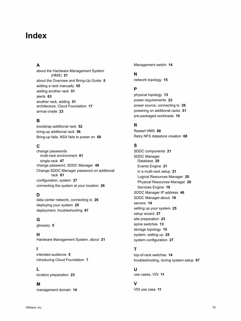
Index
Aabout the Hardware Management System
(HMS) 21about the Overview and Bring-Up Guide 5adding a rack manually 55adding another rack 51alerts 63another rack, adding 51architecture, Cloud Foundation 17arrival onsite 23
Bbootstrap additional rack 52bring-up additional rack 56Bring-up fails, NSX fails to power on 68
Cchange passwords
multi-rack environment 61single-rack 47
change password, SDDC Manager 48Change SDDC Manager password on additional
rack 61configuration, system 27connecting the system at your location 26
Ddata center network, connecting to 26deploying your system 25deployment, troubleshooting 67
Gglossary 5
HHardware Management System, about 21
Iintended audience 5introducing Cloud Foundation 7
Llocation preparation 23
Mmanagement domain 14
Management switch 14
Nnetwork topology 15
Pphysical topology 13power requirements 23power source, connecting to 26powering on additional racks 51pre-packaged workloads 10
RRestart HMS 68Retry NFS datastore creation 68
SSDDC components 21SDDC Manager
Database 20Events Engine 21in a multi-rack setup 21Logical Resources Manager 20Physical Resources Manager 20Services Engine 19
SDDC Manager IP address 46SDDC Manager:about 19servers 14setting up your system 25setup wizard 27site preparation 23spine switches 13storage topology 15system, setting up 25system configuration 27
Ttop-of-rack switches 14troubleshooting, during system setup 67
Uuse cases, VDI 11
VVDI use case 11
VMware, Inc. 79

VDI workloads 10VI use case 10VI workloads 10VIA 19Virtual Desktop Infrastructure, use case 11VMware SDDC product documentation 71
Wworkload use cases, VI 10workloads, pre-packaged 10
VMware Cloud Foundation Overview and Bring-Up Guide
80 VMware, Inc.