Embed Size (px)
Citation preview
VMware Cloud Foundation Overviewand Bring-Up Guide
Modified on 27 SEP 2017VMware Cloud Foundation 2.2

VMware Cloud Foundation Overview and Bring-Up Guide
2 VMware, Inc.
You can find the most up-to-date technical documentation on the VMware Web site at:
https://docs.vmware.com/
The VMware Web site also provides the latest product updates.
If you have comments about this documentation, submit your feedback to:
Copyright © 2015 – 2017 VMware, Inc. All rights reserved. Copyright and trademark information.
VMware, Inc.3401 Hillview Ave.Palo Alto, CA 94304www.vmware.com

Contents
About the VMware Cloud Foundation Overview and Bring-Up Guide 5
1 About VMware Cloud Foundation 7
Features and Benefits 8Private Cloud Deployment Options 9Cloud Foundation Use Cases 9Physical Topology 11Network Topology 13Storage Topology 13
2 Cloud Foundation Architecture 15
Workload Domains 15Architecture Models 17Cloud Foundation Components 18SDDC Components of Cloud Foundation 20
3 Cloud Foundation Initial Bring-Up 23
Collect Information Required for Bring-Up 24Connect First Rack to Your Power Source 25Initiate the Cloud Foundation Bring-Up Process on First Rack 26Change SDDC Manager Password 34Connect Rack to Corporate Network 35Copy Backup File to an Accessible Location 35Schedule Backup of Cloud Foundation Components 35Login to the SDDC Manager Dashboard 35
4 Adding a Rack to your Cloud Foundation System 37
Connect Additional Rack to Inter-rack Switches 37Power onAdditional Rack 38Add the Additional Rack to your Cloud Foundation System 38
5 Troubleshooting Cloud Foundation Deployment 39
Manually Power On SDDC Manager VMs When Setting Up Your Cloud Foundation System 39Restart HMS 40Retry If Bring-Up Fails During NFS Datastore Creation 40Retry If Bring-Up Fails During NSX Power Up 40
6 Additional VMware Product Documentation 43
7 Example ToR Switch Output for L3 Configuration on Cisco ToR Switches
(9372) 45
VMware, Inc. 3

8 Cloud Foundation Glossary 49
Index 51
VMware Cloud Foundation Overview and Bring-Up Guide
4 VMware, Inc.

About the VMware Cloud Foundation Overviewand Bring-Up Guide
The VMware Cloud Foundation Overview and Bring-Up Guide provides an overview of theVMware Cloud Foundation product and its components and describes the steps for setting up andconfiguring a Cloud Foundation system.
Intended AudienceThe VMware Cloud Foundation Overview and Bring-Up Guide is intended for data center cloud administratorswho deploy a Cloud Foundation system in their organization's data center. The information in this guide iswritten for experienced data center cloud administrators who are familiar with:
n Concepts of virtualization and software-defined data centers
n Networking and concepts such as uplinks, NICs, and IP networks
n Hardware components such as top-of-rack (ToR) switches, inter-rack switches, servers with directattached storage, cables, and power supplies
n Methods for setting up physical racks in your data center
n Using the VMware vSphere® Web Client™ to work with virtual machines
Related PublicationsThe Administering VMware Cloud Foundation contains detailed information about how to administer andoperate a Cloud Foundation system in your data center.
Your Cloud Foundation system includes various VMware software products and components. You can findthe documentation for those VMware software products at docs.vmware.com.
Cloud Foundation GlossaryThe Cloud Foundation Glossary defines terms specific to Cloud Foundation.
VMware, Inc. 5

VMware Cloud Foundation Overview and Bring-Up Guide
6 VMware, Inc.

About VMware Cloud Foundation 1VMware Cloud Foundation is the unified SDDC platform that brings together vSphere, vSAN, and NSX intoa natively integrated stack to deliver enterprise-ready cloud infrastructure for the private and public cloud.
APP
OSAPP
OSAPP
OSAPP
OSAPP
OSAPP
OS
SDDC Manager - Automated Lifecycle Management
Public cloud
NSX Virtual SANvSphere
Private cloud
The VMware Cloud Foundation Overview and Bring-Up Guide focuses on the private cloud use case.Deploying VMware Cloud Foundation on qualified vSAN Ready Nodes.(http://link.brightcove.com/services/player/bcpid2296383276001?bctid=ref:video_deploy_cloud_foundation_hardware)
To manage the logical infrastructure in the private cloud, Cloud Foundation augments the VMwarevirtualization and management components with a new component, SDDC Manager. SDDC Manager is theinterface for managing the infrastructure. From this interface, the IT administrator can provision newprivate cloud resources, monitor changes to the logical infrastructure, and manage lifecycle and otheroperational activities.
This chapter includes the following topics:
n “Features and Benefits,” on page 8
n “Private Cloud Deployment Options,” on page 9
n “Cloud Foundation Use Cases,” on page 9
n “Physical Topology,” on page 11
n “Network Topology,” on page 13
n “Storage Topology,” on page 13
VMware, Inc. 7

Features and BenefitsIn addition to the core features and capabilities provided by the individual components of the softwarestack, Cloud Foundation adds several unique capabilities.
Natively Integrated Software-Defined StackCloud Foundation delivers a natively integrated software-defined data center stack that includes the coreinfrastructure virtualization, vSphere, vSAN and NSX. In addition, Cloud Foundation includesCloud Foundation, which automates the entire system lifecycle (from initial bring-up, to configuration andprovisioning, to upgrades and patching), and simplifies day-to-day management and operations. You canoptionally deploy other software components such as VMware Horizon.
Automates Hardware and Software Bring-UpCloud Foundation automates the installation of the VMware software stack. Once the physical componentshave been installed in the rack, cabled, and powered on, SDDC Manager leverages its knowledge of thehardware bill of materials and user-provided environmental information (such as DNS, IP address pool,etc.) to configure the hardware components in the rack and deploy the SDDC software stack. Time savingsvaries by customer, but software installation time is estimated to be reduced from several weeks to as littleas two hours due to the automation of certain previously manual functions. These include provisioning themanagement domain, including automated provisioning of networks, and allocation of resources based onservice needs. When the process completes, you has a virtual infrastructure ready to start deployingvSphere clusters and provisioning workload domains.
Simplifies Resource Provisioning by Creating Workload DomainsCloud Foundation introduces a new abstraction, workload domains, for creating logical pools acrosscompute, storage, and networking. A workload domain is a policy based resource container with specificavailability and performance attributes that combines vSphere, vSAN and NSX into a single consumableentity.
There are two types of workload domains - the management domain (contains the management componentsto manage the infrastructure) and compute workload domains.
Each workload domain provides the needed capacity with specified policies for performance, availability,and security. For example, a cloud administrator can create one workload domain for test workloads thathave balanced performance and low availability requirements, while creating a separate workload domainfor production workloads requiring high availability and high performance.
SDDC Manager automatically implements a deployment workflow to translate the workload domainspecifications into the underlying pool of resources. Workload domains automate the provisioning ofinfrastructure in accordance with best practices, making it easy to achieve operational goals.
A workload domain can be created, expanded, and deleted as part of the SDDC lifecycle operations.
Automates Lifecycle ManagementData center upgrades and patch management are typically manual, repetitive tasks that are prone toconfiguration and implementation errors. Validation testing of software and hardware firmware to ensureinteroperability among components when one component is patched or upgraded requires extensive qualityassurance testing in staging environments. Often strapped for time, IT must sometimes make the difficultdecision to deploy new patches before they are fully vetted or defer new patches, which slows down theroll-out of new feature or security and bug fixes. Both situations increase risk for the private cloudenvironment.
VMware Cloud Foundation Overview and Bring-Up Guide
8 VMware, Inc.

SDDC Manager automates upgrade and patch management for the SDDC software stack, thereby freeingresources to focus on business critical initiatives, while improving reliability and consistency.
Lifecycle management in SDDC Manager can be applied to the to the SDDC software stack or to individualworkload domains, and is designed to be non-disruptive to tenant virtual machines (VMs). By utilizing liveVM migration together with vSphere Dynamic Resource Scheduler (DRS), SDDC Manager can patchsoftware to improve infrastructure security and reliability. VMware does extensive validation testing of thesoftware stack prior to releasing software updates, which reduces risk and helps to instill confidence.
Integrates Management of Physical and Virtual InfrastructureSDDC Manager understands the physical and logical topology of the software defined data center and theunderlying components’ relation to each other, and efficiently monitors the infrastructure to detect potentialrisks, degradations and failures. SDDC Manager provides stateful alert management to prevent notificationspam on problem detection. Each notification includes a clear description of the problem and providesremediation actions needed to restore service. Degradations or failures are aggregated and correlated toworkload domains to enable a clear view of the impact of any issue to the business services being deployedwithin a domain. Therefore, SDDC Manager can greatly reduce the mean time to resolution acrossorganizational and technology silos.
Scalability and PerformanceCloud Foundation delivers a private cloud instance that can be easily deployed within an existing corporatenetwork. Based on a scale-out, hyper-converged architecture, a Cloud Foundation implementation can startcan start with a single rack containing four servers. Additional capacity and performance can easily beadded linearly in increments as small as one server at a time within a single rack, scaling out to eight fullracks containing 256 servers. Cloud Foundation adds the new capacity into the larger pool of availablecapacity for use.
Private Cloud Deployment OptionsCloud Foundation provides flexibility in choosing on-premises deployment options.
Customers begin by sizing their Cloud Foundation deployment to determine the number of physical serversin their rack. You then have two deployment options for Cloud Foundation
n Deploy the Cloud Foundation software on qualified vSAN ReadyNodes in your datacenter.
Customers can start with qualified hardware (qualified ReadyNodes and qualified switches) in theirdatacenter, wire it up, and deploy the Cloud Foundation software stack on the ready system. Forinformation on qualified hardware, see VMware Compatibility Guide.
n Purchase a fully integrated system that combines software and hardware from select VMware partners.
The partner works with a VMware representative to complete the Site Readiness document. Thistranslates into a bill of materials (BoM) consisting of both hardware and software components. With thisBoM in hand, the partner assembles the rack and images it. The partner then ships the system,consisting of physical racks, servers, server sub-components, power distribution units, switchinginfrastructure and the Cloud Foundation software, to customers.
Cloud Foundation Use CasesCloud Foundation includes two pre-packaged workload domain types, Virtual Infrastructure (VI) andVirtual Desktop Infrastructure (VDI). A workload domain is a policy based resource container with specificavailability and performance attributes and combining vSphere, vSAN and NSX into single a consumableentity. The following sub-sections discuss how Cloud Foundation implements each of these workloaddomains.
Chapter 1 About VMware Cloud Foundation
VMware, Inc. 9

Virtual InfrastructureWith Cloud Foundation, you have a complete solution to run your SDDC infrastructure. Cloudadministrators have the ability to allocate and reclaim the underlying infrastructure to meet their changingbusiness needs. With a cloud that is based on the market leading virtualization platform, lines of businesshave the flexibility to deploy a wide variety of operating systems and application stacks within the tenantVMs. Virtual infrastructure administrators can integrate with and monitor the underlying infrastructureusing a common monitoring tool set that aggregates and correlates across physical and virtualinfrastructure. In addition, you have the flexibility to integrate your vSphere compatible tools directly withvCenter Server.
VI configures a flexible virtual datacenter with the ability to deploy and configure OS instances in the formof VMs with vCPUs, memory, and storage including networking resources.
You can acquire modular Cloud Foundation units to match your consumers' data center capacityrequirements and offer the resulting virtual infrastructure to your consumers with minimal overhead. SDDCManager deploys the following for a VI workload:
n Physical compute
The administrator specifies the required capacity and SDDC Manager determines how many servers areneeded and decides which servers use.
n Virtual infrastructure
One vCenter Server is deployed per workload domain, which connects to the Platform ServicesController in the management domain for credentials and licenses. SDDC Manager creates workloaddomains according to your specifications, adding hosts and creating vSAN datastores from the storageon those hosts. It also deploys and configures distributed virtual switches on each host.
n Physical networking
SDDC Manager configures the ToR switches to accept traffic for the VLANs created in the virtualinfrastructure and to route traffic for the public logical networks of the workload domain.
n Log Aggregation
Cloud Foundation allows administrators to aggregate logs using vRealize Log Insight.
Virtual Desktop InfrastructureWith Cloud Foundation, you can deliver hosted desktops and applications through a single Virtual DesktopInfrastructure (VDI) platform with VMware VMware Horizon. End users can access all of their desktopsand applications through a single unified workspace.
When deploying a VDI workload domain, Cloud Foundation automates the deployment and configurationof all required components. SDDC Manager performs the following tasks during a VDI workload domaincreation:
n Physical compute
Hosts for the workload domain are selected from the hosts in the available inventory based upon thesizing requirements for the environment. Each host includes processing, storage, and networkconnectivity.
n Virtual infrastructure
One vCenter Server is deployed per workload domain, which connects to the Platform ServicesController in the management domain for credentials and licenses. The workload domain is createdaccording your specifications, adding hosts and creating vSAN datastores from the storage on thosehosts. Distributed virtual switches are deployed on each host.
VMware Cloud Foundation Overview and Bring-Up Guide
10 VMware, Inc.

n Physical networking
SDDC Manager uses the HMS to configure the switches to accept traffic for the VLANs created in thevirtual infrastructure and to route traffic for the public logical networks of the workload domain.
n Log Aggregation
Cloud Foundation allows administrators to aggregate logs using vRealize Log Insight.
n VDI
VMware Horizon is bundled with Cloud Foundation and automates the deployment of ViewConnection Servers, security servers, App Volumes, Composer Server, and a DHCP Relay Agent.Cloud Foundation also creates an initial desktop pool.
Physical TopologyA Cloud Foundation system can include up to eight physical racks.
Figure 1‑1. Physical Topology
KEMP
NICs CPU Memory SSD HDD Mgmt port
HMS
Cloud Foundation API
Cloud Foundation UIvRealize OperationvRealize Log Insight
Workload Management
NSX Manager
NSX
vCenter Server
VSAN
Har
dwar
e
vSphere
HMS
ManagementSwitch
Cloud Foundation API
VI / VDI
SDDC Manager
Virt
ualiz
atio
nO
pera
tions
and
Man
agem
ent
(OA
M)
Host 0 appliance
Chapter 1 About VMware Cloud Foundation
VMware, Inc. 11

Inter-rack SwitchesThe Cloud Foundation system contains two inter-rack switches. These switches extend the network fabric ofthe top of rack (ToR) switches between racks and are used for inter-rack connectivity only. The availableuplink ports of the ToR switches are connected to the inter-rack switches.
Inter-rack switches are required only in multi-rack installations of Cloud Foundation and are typicallyplaced in the second rack.
Management SwitchThe management switch provides Out-Of-Band (OOB) connectivity to the baseboard management controller(BMC) on each server.
The management network fabric does not carry vSphere management, vSAN, or vMotion traffic. That trafficresides on the network fabric created by the ToR and inter-rack switches. As a result the management switchis a non-redundant component in the physical rack. If this switch goes down, some functionality such asmonitoring may not be available until it comes back up. Workloads will continue to run, but theinfrastructure associated with them cannot be modified or controlled.
Top of Rack SwitchesA physical rack contains two top of rack (ToR) switches. The ToR and inter-rack switches carry all networktraffic from the servers including VM network, VM management, vSAN, and vMotion traffic. The ToRswitches in the first rack carry all traffic to the enterprise network via two of the uplink ports. The ToRswitches provide higher bandwidth as well as redundancy for continued operation in case one of them goesdown.
If the installation has inter-rack switches, two uplink ports from each ToR switch on each rack are connectedto each inter-rack switch.
ServersThis section contains information about supported server models and component configurations.
For information on supported hardware, see VMware Compatibility Guide.
Table 1‑1. Server Configuration for Cloud Foundation
Component Minimum Maximum
CPU perserver
Dual-socket, 8 cores per socket Dual-socket, no maximum on cores per socket
Memory perserver
256 GB 1.5 TB
Storage perserver
4 TB for capacity tier. Follow vSAN guidelines forcache tier sizing as described in VMware vSANDesign and Sizing Guide.For high performance workload domains, eachserver to be used in the domain must contain at least3 capacity tier disks.Note Cloud Foundation only supports vSANRAID controllers in pass-through mode.
8 disks per controller. Follow vSAN guidelinesfor cache tier sizing as described in VMwarevSAN Design and Sizing Guide.
NICs perserver
Two 10 GbE NICs and one 1 GbE BMC NIC Two 10 GbE NICs and one 1 GbE BMC NIC
VMware Cloud Foundation Overview and Bring-Up Guide
12 VMware, Inc.

Table 1‑1. Server Configuration for Cloud Foundation (Continued)
Component Minimum Maximum
Servers perrack
Four 1U or 2U serversA minimum of 7 servers are required for workloadcreation.
32 1U servers or 16 2U servers
Rack 1 8
Network TopologyEach host in the physical rack is connected to the two ToR switches with separate 10Gb links. On each host,NIC port 1 is connected to ToR switch 1 and NIC port 2 is connected to ToR switch 2 with Link Aggregation(LAG).
The BMC on each host is connected to the management switch over a 1G connection. This connection is usedfor OOB management. In a multi-rack system, both ToR switches are further connected to a pair of inter-rackswitches in a dual-LAG configuration using 40 G links. The inter-rack switches are an aggregation layer forconnecting multiple racks.
Cloud Foundation is designed to be resilient to certain network failures. The datapath between hosts andToR switches can tolerate a failure of one link between the host and ToR switches. Between the ToR andinter-rack switches, the system can tolerate the failure of a ToR switch and/or inter-rack switch.
Storage TopologyThe primary source of storage for Cloud Foundation is vSAN. For example, a 1U server can have 8 disks inthe capacity tier and 2 disks in the caching tier. All disks are claimed by vSAN for storage.
The amount of available physical storage in workload domains depends on the number of physical hosts.The amount of usable capacity depends on availability requirements.
Storage traffic is carried over the 10Gbps links between the hosts and ToR switches. There is a dedicatedvSAN port group defined on the vDS. All vSAN members communicate over this 10 Gbps network.
vSphere Network I/O Control (NIOC) can be enabled to allow network resource management to usenetwork resource pools to prioritize network traffic by type.
Chapter 1 About VMware Cloud Foundation
VMware, Inc. 13

VMware Cloud Foundation Overview and Bring-Up Guide
14 VMware, Inc.

Cloud Foundation Architecture 2Cloud Foundation orchestrates, provisions, and deploys a software defined data center (SDDC). It maps aconverged view of physical resources (e.g., CPU, memory, storage, and network) to a logical abstraction.Cloud Foundation overlays a software suite on top of the physical hardware for operations management,event reporting, and auditing. This enables Cloud Foundation to provide consistent hardware managementacross switches, servers, and storage, as well as a consolidated management solution across your SDDC.
In addition to the SDDC software stack, Cloud Foundation includes SDDC Manager, an application thatautomates the entire SDDC lifecycle (from initial bring-up, to configuration and provisioning, to upgradesand patching), and simplifies day-to-day management and operations. SDDC Manager offers a web-basedinterface.
This chapter includes the following topics:
n “Workload Domains,” on page 15
n “Architecture Models,” on page 17
n “Cloud Foundation Components,” on page 18
n “SDDC Components of Cloud Foundation,” on page 20
Workload DomainsA workload domain is a policy based resource container with specific availability and performanceattributes that combines compute (vSphere), storage (vSAN) and networking (NSX) into a singleconsumable entity.
Management DomainThe management domain is a special-purpose workload domain dedicated to infrastructure andmanagement tasks.
During bring-up, the management domain is automatically created on a four host vSAN cluster on the firstrack in a Cloud Foundation system. It contains the following management components:n SDDC Manager
n vCenter Server and Platform Services Controllers
n vRealize Log Insight
VMware, Inc. 15

n NSX
Figure 2‑1. Management Domain Components
Management Resource Pool
Platform ServicesControllers
NSXControllers
vCenter Server NSXManager
SDDC ManagerUtility VM
SDDC ManagerControl VM
Log InsightCluster
ESXi Host 1 ESXi Host 2 ESXi Host 3 ESXi Host 4
Management VSAN Datastore
vSphere Distributed Switch
NSX vSwitch (DFW, DLR, VTEP)
Compute Resource Pool
Compute Workload DomainsCompute workload domains can be either VI or VDI, and are created on-demand by Cloud Foundationadministrators. A compute workload is provisioned on a vSAN with a minimum of three hosts. Eachworkload domain is created according to user specified size, performance, and availability. For example, acloud administrator can create one workload domain for test workloads that have balanced performanceand low availability requirements, while creating a separate workload domain for production workloadsrequiring high availability and high performance.
A compute workload domains contains the following software components:
n vCenter Server
n NSX
In addition to the above components, VDI workload domains also contain VMware Horizon.
VMware Cloud Foundation Overview and Bring-Up Guide
16 VMware, Inc.
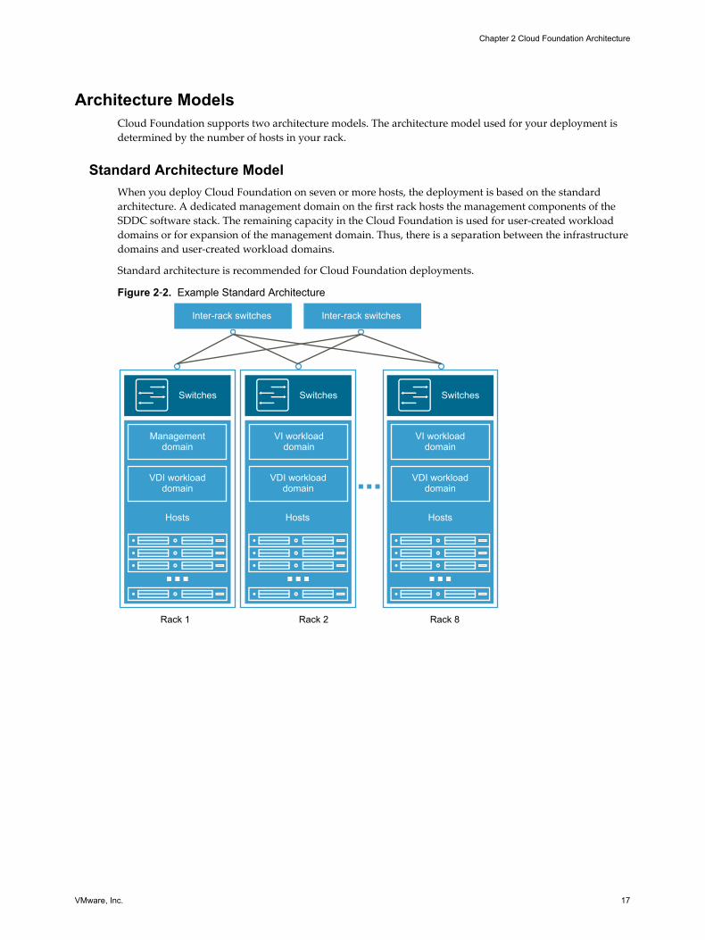
Architecture ModelsCloud Foundation supports two architecture models. The architecture model used for your deployment isdetermined by the number of hosts in your rack.
Standard Architecture ModelWhen you deploy Cloud Foundation on seven or more hosts, the deployment is based on the standardarchitecture. A dedicated management domain on the first rack hosts the management components of theSDDC software stack. The remaining capacity in the Cloud Foundation is used for user-created workloaddomains or for expansion of the management domain. Thus, there is a separation between the infrastructuredomains and user-created workload domains.
Standard architecture is recommended for Cloud Foundation deployments.
Figure 2‑2. Example Standard Architecture
Switches
Hosts Hosts
Managementdomain
VDI workloaddomain
VDI workloaddomain
VI workloaddomain
Hosts
VDI workloaddomain
VI workloaddomain
Rack 1 Rack 2 Rack 8
Switches Switches
Inter-rack switches Inter-rack switches
Chapter 2 Cloud Foundation Architecture
VMware, Inc. 17

Consolidated Architecture ModelWhen you deploy Cloud Foundation on six or fewer hosts, deployment is based on the consolidatedarchitecture. In this model, both the infrastructure and compute workload domains run a shared vSpherecluster. Resource pools provide isolation for the different workload types.
As you add additional hosts to a Cloud Foundation system deployed on a consolidated architecture, you canconvert to the standard architecture by creating a compute workload domain outside the managementdomain and moving the workload domain VMs from the compute resource pool to the newly createdworkload domain. When moving these VMs, you must update shares and reservations on the computeresource pool.
Figure 2‑3. Sample Consolidated Architecture
Switches
6 or less hosts
Computeresource pool
Managementresource pool
Managementdomain
Rack 1
Cloud Foundation Components
VIAVIA is a virtual appliance used to image the first rack, additional racks, and individual servers. Duringimaging, VIA pre-configures the SDDC software stack on the rack. For more information, see VIA User'sGuide.
SDDC ManagerSDDC Manager manages the bring-up of the Cloud Foundation system, creates and manages workloaddomains, and performs lifecycle management to ensure the software components remain up-to-to date.SDDC Manager also monitors the logical and physical resources of Cloud Foundation.
As you expand your Cloud Foundation system by adding hosts or racks, SDDC Manager allows data centeradministrators to configure the additional hosts and racks into a logical pool of resources. This consolidatescompute, storage, and networking resources of the racks available for assignment to workload domains.Thus, multiple racks can be managed as a single Cloud Foundation system.
VMware Cloud Foundation Overview and Bring-Up Guide
18 VMware, Inc.

SDDC Manager controls these processes by using workflows. Each workflow comprises of a series of tasks,which are executed by SDDC Manager. By doing so, SDDC Manager ensures that if any high level task suchas bring-up or upgrade fails, it can identify the exact point of failure, and continue the process from thatpoint onward.
SDDC Manager VMs contain multiple services, each responsible for the different APIs providing lifecyclemanagement for the SDDC.
SDDC Manager Controller VMThe SDDC Manager Controller VM includes the logic for deploying the software stack, managing workloaddomains, managing hardware tasks, and performing lifecycle management. It provides a persistent datastore.
Bring-Up Service
The bring-up service deploys the SDDC software stack on your physical rack. It creates the managementdomain on the first rack in a Cloud Foundation system. A resource pool is created on the managementdomain which can contain user-created workload domain VMs.
Manager Service
The Manager Service manages the SDDC stack. It creates, expands, and deletes workload domainsaccording to your specifications.
LCM Service
LCM service performs lifecycle management on the Cloud Foundation software as well as the VMwaresoftware components included in the SDDC software stack.
System Controller Service
The System Controller Service starts the other SDDC Manager services and also re-starts them whennecessary.
Events Engine
The events engine pushes SDDC Manager events to vRealize Log Insight. The events engine process can alsodisplay events information on the SDDC Manager UI dashboard.
Hardware Management Services
The Hardware Management Services (HMS) manages the hardware in the Cloud Foundation system, suchas hosts and network switches. It provides the necessary functions required for discovering, bootstrapping,and monitoring the hardware. HMS runs on the SDDC Manager Controller VM, where it can access all hostsand switches on the out-of-band network.
HMS works with both vendor-provided plug-ins and VMware plug-ins, and gives the SDDC Manager thecapability to interact with the hardware. The HMS is only accessed through the SDDC Manager and is notvisible to system administrators.
Chapter 2 Cloud Foundation Architecture
VMware, Inc. 19

SDDC Manager Utility VMThe SDDC Manager Utility VM contains the downloaded LCM update bundles, as well host-level and NSXbackup files.
SDDC Components of Cloud FoundationThis section describes how the SDDC software components work within a Cloud Foundation system.
ESXiESXi is a type 1 hypervisor used to implement virtualization on bare metal systems. ESXi provides forcompute virtualization within the software-defined data center and is a foundational building block forimplementing a private cloud.
Cloud Foundation uses ESXi as the foundation for creating workload domains. SDDC Manager groupshosts into vSphere clusters managed by vCenter Server. vSphere HA provides high availability to protectagainst ESXi host failures.
vCenter ServervCenter Server provides for management of a VMware virtualized environment with one or more ESXihosts. SDDC Manager deploys one vCenter Server per workload domain. By default, all vCenter Servers areconfigured in enhanced linked mode.
Platform Services ControllersDuring bring-up, SDDC Manager deploys two Platform Services Controllers in the management domain.These instantiate an SSO domain. All vCenter Servers (management domain and compute workloaddomains) are registered with the SSO domain and configured in enhanced link mode.
vSANvSAN provides storage systems for the SDDC. It pools together local flash devices and/or hard disks toprovide a highly resilient shared datastore suitable for a variety of workload domains including business-critical applications, virtual desktops, remote IT, DR, and DevOps infrastructure.
In Cloud Foundation, each workload domain contains one vSphere cluster. The SDDC Manager creates asingle vSAN volume spanning all the hosts within each vSphere cluster. It is recommended that you use aminimum of four hosts per workload domain for vSAN.
In an all flash vSAN environment, you must mark flash devices to be used for capacity layer as capacitydisks. See the Administering VMware Cloud Foundation guide for more information.
NSXNSX is the network virtualization platform for the SDDC, delivering the operational model of a virtualmachine for entire networks. With NSX, network functions including switching, routing, and firewalling areembedded in the hypervisor and distributed across the environment.
NSX comprises of one NSX Manager and three Controllers. NSX Manager maps to a single vCenter Serverenvironment. Therefore, each workload domain includes one NSX Manager instance and three NSXController instances.
Data center administrators can use the vSphere Web Client to perform additional NSX configurationrequired by the specific VMs deployed within the workload domain.
VMware Cloud Foundation Overview and Bring-Up Guide
20 VMware, Inc.

vRealize Log InsightvRealize Log Insight delivers heterogeneous and highly scalable log management with intuitive, actionabledashboards, sophisticated analytics and broad third-party extensibility, providing deep operational visibilityand faster troubleshooting.
Cloud Foundation configures vRealize Log Insight on the management domain in a three node cluster. WithvRealize Log Insight, administrators can monitor logs for both the physical and virtual components througha single interface. The default vRealize Log Insight license covers the management domain. You need toprovide an additional license for using vRealize Log Insight with workload domains.
Chapter 2 Cloud Foundation Architecture
VMware, Inc. 21

VMware Cloud Foundation Overview and Bring-Up Guide
22 VMware, Inc.

Cloud Foundation Initial Bring-Up 3The initial configuration of a newly deployed Cloud Foundation rack is called bring-up.
During bring-up, the system creates a management cluster and deploys the core management componentVMs in the management cluster. You can then create workload domains on your Cloud Foundationsystem.
the minimum number of servers supported is 4.
The physical rack must contain at least four hosts for bring-up. These are used to create the managementdomain, which can also used to host user provided workload domains. To create another workload domainin addition to the initial management domain, another three hosts are required.
The bring-up process involves several steps. If you have multiple racks in your Cloud Foundation system,you must complete bring-up on rack 1 before configuring the remaining racks.
Prerequisites
Verify that you have met the following prerequisites.
n You have an imaged rack (where SDDC software is pre-configured on the rack) with the appropriatenumber of hosts.
n You have a laptop with a supported web browser, from where you will run the bring-up process. For alist of supported browser versions, see the VMware Cloud Foundation Release Notes.
Procedure
1 Collect Information Required for Bring-Up on page 24During the bring-up process, you are required to provide company domain, management network,and vSAN, VXLAN, and datacenter network settings. You must collect this information before startingthe bring-up process.
2 Connect First Rack to Your Power Source on page 25Power on the first rack.
3 Initiate the Cloud Foundation Bring-Up Process on First Rack on page 26After you provide site specific information for the bring-up process such as rack name, passwords, IPaddresses, and DNS and NTP details, SDDC Manager configures your private cloud.
4 Change SDDC Manager Password on page 34During imaging, the SDDC Manager password is set to vmware1234. This is the password used duringinitial bring-up. For security reasons, you must change this password before connecting the rack toyour corporate network.
5 Connect Rack to Corporate Network on page 35You can now connect the Cloud Foundation rack to your corporate network.
VMware, Inc. 23

6 Copy Backup File to an Accessible Location on page 35Copy the files of the backup taken during bring-up to an accessible location.
7 Schedule Backup of Cloud Foundation Components on page 35Schedule a periodic backup for your Cloud Foundation environment.
8 Login to the SDDC Manager Dashboard on page 35
Collect Information Required for Bring-UpDuring the bring-up process, you are required to provide company domain, management network, andvSAN, VXLAN, and datacenter network settings. You must collect this information before starting the bring-up process.
Table 3‑1. Description of Networks
Title Description
vSANnetwork
Network for vSAN and vSphere HA inter-host communication.
vMotionnetwork
Network for vMotion across hosts.
Non-routablenetwork
Network for internal communication between Cloud Foundation management components.
Managementnetwork
Network that provides public access to Cloud Foundation components in the management domain.
Data centernetwork
Network used to access customer VMs.
VMware recommends that you print this table and fill in the required values. Keep this printout handyduring the bring-up process.
Table 3‑2. Information Required for Bring-Up
Information Required Example Value
Rack nameEach rack in the Cloud Foundation system must be assigned aunique name.Rack names allow you to map the IDs SDDC Manager assigns toa host or a switch with the physical rack containing the host orswitch. You need to specify the rack name during bring-up andwhile adding a rack. A best practice is to specify the nameaffixed to the physical rack along with location details such asthe datacenter the rack is located in.
ABC
Company name My Company
Department My department
Root DNS DomainMust be the same as the domain defined in DNS naming system.
mycompany.local
Sub-domain for the Cloud Foundation system. Each rack in theCloud Foundation system must have a unique sub-domain.
vcf01-domain.mycompany.local
SSO domain for the Cloud Foundation system. mycompany.local
Cloud Foundation license key 11111-11111-11111-11111-11111
VLAN ID for management networkSupported VLAN range is 21-3299.
21
VMware Cloud Foundation Overview and Bring-Up Guide
24 VMware, Inc.

Table 3‑2. Information Required for Bring-Up (Continued)
Information Required Example Value
Subnet for management networkMust be at least a /22 network to allow for expansion of theCloud Foundation system.
255.255.0.0
Subnet mask for management networkA /22 network is recommended to allow for expansion of theCloud Foundation system.
222.222.222.0
Gateway for management resources 10.0.0.000
Primary DNS for management resources 10.172.40.1
Secondary DNS for management resources 10.172.40.2
VLAN ID, subnet, subnet mask, and gateway for vMotion,vSAN, VXLAN, and data center networks. You can either usesystem generated values for these, or specify your own values.
NTP server for the Cloud Foundation system. 192.168.100.100
IP address range to be excludedIf you have already used a set of IP addresses in your detacenteror do not want to use certain IP addresses, you can exclude themfrom Cloud Foundation provisioning.
Choose uplink type L2 or L3If you choose L3, you will also need the upstream router (nexthop) information.
L2
Whether uplink LAG is to be enabledLAG (Link Aggregation Group) aggregates multiple links into asingle bundle. You can enable this option if the speeds on theports in your environment match. For example, if you have 4uplink ports at 10G, you can get up to 40G with LAG enabled.
Yes
Uplink ToR ports10 GB ports: 43-4640 GB ports: 51-54
43, 44
Uplink speedOptions are 1 GB, 10 GB, 40 GB
10 GB
Connect First Rack to Your Power SourcePower on the first rack.
Note Do not connect the rack to your corporate network till after the bring-up process is complete.
Procedure
1 Connect the rack's power inlets to your power source.
2 Connect port 48 of the first rack's management switch to the laptop from where you will run the bring-up process.
3 Configure the laptop NIC to tag VLAN traffic.
Chapter 3 Cloud Foundation Initial Bring-Up
VMware, Inc. 25

4 Create a trunked interface on the laptop.
a Assign the 192.168.100.248/22 IP address/subnet mask to the untagged interface. The untaggedinterface will allow private network access to Cloud Foundation hardware and Softwarecomponents
b Tag interface 2 with the management VLAN ID (refer to the table where you had noted thesedetails) and assign an IP address/subnet mask from the upper end of the management network IPaddress pool used for management workload domains.
This interface will allow for hardware access to the system if there is an uplink mis-configurationand the system is unreachable from the upstream customer network.
What to do next
1 Ping the SDDC Manager Controller VM VM at 192.168.100.40. If you are unable to ping the VM, contactVMware support.
2 Open the browser on the laptop and navigate to http://192.168.100.40:8008/login. If the browser does notdisplay the setup wizard, the SDDC Manager VMs might not be powered on. Verify whether they arerunning and, if not, power them on as described in “Manually Power On SDDC Manager VMs WhenSetting Up Your Cloud Foundation System,” on page 39.
Continue with the steps in “Initiate the Cloud Foundation Bring-Up Process on First Rack,” on page 26.
Initiate the Cloud Foundation Bring-Up Process on First RackAfter you provide site specific information for the bring-up process such as rack name, passwords, IPaddresses, and DNS and NTP details, SDDC Manager configures your private cloud.
If you accidentally log out of the browser while the configuration process is running, the process continuesto progress. You can log back in to continue the configuration.
Prerequisites
1 Ensure that you have completed the steps in “Connect First Rack to Your Power Source,” on page 25.
2 Either turn off the firewall on the jump host or ensure that the firewall ports required to accessCloud Foundation are open.
Table 3‑3. Inbound Ports for Cloud Foundation
Port Required for
TCP 8443 SDDC Manager
TCP/UDP 53 DNS resolution to SDDC Manager
TCP 22 (optional) SSH access to Cloud Foundation and vSphere components
Table 3‑4. Outbound Ports for Cloud Foundation
Port Required for
TCP/UDP 53 Corporate DNS resolution
UDP 123 NTP access to corporate time servers
In addition, other VMware software included in Cloud Foundation may require additional firewallports to be open.
n vCenter Server and ESXi KB article
n VMware Horizon KB article
n Platform Services Controller
VMware Cloud Foundation Overview and Bring-Up Guide
26 VMware, Inc.

Login to Cloud FoundationYou begin by logging in to the wizard.
Procedure
1 After you power on the rack, wait at least 10 minutes before proceeding to the next step. This ensuresthat all rack components are powered on.
2 In a web browser on the laptop that is connected to port 48 of the rack's management switch, navigateto https://192.168.100.40:8008/login.
The Welcome page appears.
3 Type the default credentials:
User name: [email protected]
Password: vmware1234
4 Click LOG IN and then click START BRING-UP.
The VMware Cloud Foundation page appears.
Rack DiscoveryDuring the rack discovery phase of the bring-up process, the system communicates with the servers andswitches.
If the servers are available and the switches can be accessed, the physical inventory is populated. When thisis completed, a green check mark appears next to Rack Discovery on the Welcome page and the Continuebutton on the bottom of the page is enabled.
n Click CONTINUE.
If is a hardware issue detected, you must fix it and click Re-try.
Set System Date and TimeAfter the hardware components on the physical rack have been discovered, you set the date and time for therack. The specified time is set on all operational hosts, switches, and the SDDC Manager VM.
Procedure
1 Select the date on the calendar.
2 Set the time.
The specified time should match the current time in your environment.
3 Select the time zone for the rack.
4 Click SET TIME.
The page displays the progress of the set time task. If time set fails on any component other than SDDCManager VMs, you can either re-try this task or proceed with the rest of the workflow. Time is syncedlater during the bring-up workflow.
If time set on the SDDC Manager VMs fails, you must retry setting the time. If the retry fails, reboot theSDDC Manager VMs and retry the time set task.
After the time has been set on all Cloud Foundation components, the CONTINUE button is enabled.
5 Click CONTINUE.
The Power On System Validation page is displayed.
Chapter 3 Cloud Foundation Initial Bring-Up
VMware, Inc. 27

Power On System (POSV) ValidationPower On System Validation applies a set of pre-defined rules to assess whether bootstrapping can bestarted on the rack. Alerts related to hardware issues are displayed so that you can fix the problems beforebootstrapping begins. You must ensure that the hardware is healthy before bring-up begins. The bring-upservice will skip hosts that cannot be configured.
The status bar on the Power On System Validation page displays the task progress. The Tasks tab displaysthe date and time that each validation task was performed. After the validation is complete, the Continuebutton is enabled.
Alert notifications are also displayed here. The Alerts tab displays alert severity and remediation details.You can download or print the task or alert list. After you fix the issue reported by an alert, click Resolve. Ifyou cannot take the remediation steps displayed on the alert, you can continue bring-up. Hosts with issuesare not configured during bring-up.
Procedure
1 Click CONTINUE.
If POSV fails, take the necessary action and click Retry.
2 Click START DEPLOYMENT.
Initial SetupDuring initial setup, the rack is bootstrapped and the management cluster is created. The managementcluster contains the management component VMs. The remaining hosts in the physical rack are configuredfor Cloud Foundation.
Accept End User License Agreement (EULA)Displays EULA for Cloud Foundation.
Procedure
1 Read the EULA and accept it.
2 Click NEXT.
Create Super User for SDDC Manager DashboardYou create a super user account to manage the vSphere infrastructure. The super user account has the sameprivileges as the [email protected] account. After the bring-up process is complete, the passwordfor the [email protected] account is rotated to a random password, but the password for thesuper user account does not change. You can, thus, login to SDDC Manager with the super user name andpassword without having to look up the rotated password for the administrator account.
Procedure
1 Type a user name and password for the super user.
The password must be between 8 and 20 characters long and must contain at least one each of thefollowing:
n lowercase letter
n uppercase letter
n number
n special character such as ! or @
VMware Cloud Foundation Overview and Bring-Up Guide
28 VMware, Inc.

2 Click NEXT.
Specify Rack and Company Domain DetailsSpecify information about the physical rack and company domain.
Procedure
1 On the General information page, enter the following information.
Field Name Description
Physical RackName
Name by which the physical rack is to be identifiedRack names allow you to map the IDs SDDC Manager assigns to a host or a switch with thephysical rack containing the host or switch. A best practice is to specify the name affixed to thephysical rack along with location details such as the datacenter the rack is located in.
Company Name Your company name
CompanyDepartment
Your department name
Root DNSDomain
Type your root DNS domain (for example, vmware.corp).Must be the same as the domain defined in DNS naming system.
VMware CloudFoundation Sub-Domain
Cloud Foundation generates this based on the root domain you specified. For example, if youspecified the root domain as vmware.corp, the subdomain is auto-populated assubdomain.vmware.corp. You can edit this field. The Cloud Foundation sub-domain must beunique in your organization, otherwise there will be issues when you join Active Directory.The sub-domain is used for all components in Cloud Foundation. So everything is namedcomponent.subdomain. Based on our example, the NSX VM would be named rack-1-nsxmanager-1.subdomain.vmware.corp.
SSO Domain Type the authentication domain to be used by SSO. For example, vsphere.local.The root domain and PSC domain must be different if you plan to join Active Directory. If youwill not join Active Directory, they can be the same.
VMware CloudFoundationLicense Key
Optionally, type the license key for Cloud Foundation.
2 Click NEXT.
Specify Management Network DetailsSpecify network information such as the VLAN identifier and IP subnets for the management, vMotion,vSAN, and VXLAN networks. The VLAN IDs you specify here are configured on the physical switchinfrastructure.
Procedure
1 On the Management page, enter your management network values. The DNS server here is the DNSserver for your management network.
Field Name Description
VLAN ID The supported VLAN range is 24-3967.
Subnet VMware recommends using a /22 network. This is to allow for adequate IP addresscapacity as you expand your Cloud Foundation deployment by adding racks.
Subnet Mask VMware recommends using a /22 network.
Gateway Gateway address.
Primary DNS Primary DNS of your datacenter.
Secondary DNS Secondary DNS of your datacenter.
Chapter 3 Cloud Foundation Initial Bring-Up
VMware, Inc. 29

Field Name Description
NTP NTP of your datacenter.
Exclude IP AddressRanges
Enter a set of IP address ranges to exclude from the provisioning process. For example,you can exclude a range of IP addresses that you want reserved for other uses in yournetwork.To add multiple address ranges, type an IP address range, click the + sign, and type thenext IP address range.
2 Click USE DEFAULTS to allow Cloud Foundation to specify system generated IP address ranges forvMotion, vSAN, and VXLAN.
3 Click NEXT.
Specify vMotion Network SettingsIf you are using default values, review the system's vMotion network details. Otherwise, specify vMotionnetwork values.
Procedure
u Review or enter your network addresses for VLAN ID, Subnet, Subnet Mask, Gateway, and excluded IPaddresses and IP address ranges.
Note The supported VLAN range is 24-3967. VMware recommends using a /22 network for the subnetand subnet mask. This is to allow for adequate IP address capacity as you expand yourCloud Foundation deployment by adding racks.
Specify vSAN Network SettingsIf you are using default values, review the system's vSAN network details. Otherwise, specify vSANnetwork values.
Procedure
u On the vSAN Network page, review or enter your vSAN network addresses for the VLAN, Subnet,Subnet Mask, Gateway, and excluded IP address ranges.
Note The supported VLAN range is 24-3967. The subnet and subnet mask must be at least a /22network. This is to allow for adequate IP address capacity as you expand your Cloud Foundationdeployment by adding racks.
Specify VXLAN Network SettingsIf you are using default values, review the system's VXLAN network details. Otherwise, specify VXLANnetwork values.
Procedure
u On the VXLAN Network page, review or enter your VXLAN network addresses for the VLAN, Subnet,Subnet Mask, Gateway, and excluded IP address ranges.
Note The supported VLAN range is 24-3967. The subnet and subnet mask must be at least a /22network. This is to allow for adequate IP address capacity as you expand your Cloud Foundationdeployment by adding racks.
VMware Cloud Foundation Overview and Bring-Up Guide
30 VMware, Inc.

Specify Datacenter Network SettingsSpecify the network settings to connect the Cloud Foundation system to your corporate network.
Procedure
1 Enter your corporate network information for the VLAN ID, Connection Name, Network Start IP,Subnet Mask, Gateway, DNS, NTP, and excluded IP addresses and IP address ranges.
2 Type a connection name for the Cloud Foundation system.
3 Type the Subnet, Subnet Mask, and Gateway for your corporate network.
Note The supported VLAN range is 24-3967. The subnet and subnet mask must be at least a /22network. This is to allow for adequate IP address capacity as you expand your Cloud Foundationdeployment by adding racks.
4 Click NEXT.
Specify Datacenter Uplink DetailsSpecify data center uplink information. The uplink is enabled for management and data center networks.
Procedure
1 If the uplink is an L2 connection, provide the following information.
Field Description
Uplink Type L2
Uplink LAG Enabled It is recommended that you select this option.
Uplink Ports Port numbers on the ToR switches that are connected to the uplink network. Enter avalue ranging from 43 to 46.
Uplink Speed Speed for uplink connections.
Ensure that the management and external VLANs from Cloud Foundation are routable upstream.
2 If the uplink is an L3 connection, provide the following information.
Field Description
Uplink Type L3
Uplink LAG Enabled LAG (Link Aggregation Group) aggregates multiple links into a single bundle. You canenable this option if the speeds on the ports in your environment match. For example, ifyou have 4 uplink ports at 10G, you can get up to 40G with LAG enabled.
Uplink Ports Port numbers on the ToR switches that are connected to the uplink network. Enter avalue ranging from 51 to 54.
Uplink Speed Speed for uplink connections.
Uplink IP IP address of the uplink IP on the ToR switches.
Mask IP Subnet mask for the uplink IP.
Next Hop IP IP address of the uplink switch for the data center.
For an L3 uplink, SDDC Manager configures a Switched VLAN Interface (SVI) for each requestedVLAN and configures a static route between ToR 1 and the upstream router. The configured SVI andthe configuration between the ToR and router is non-HA. You need set up a method to route trafficacross the internet. This not automated during bring-up.
Chapter 3 Cloud Foundation Initial Bring-Up
VMware, Inc. 31

You can set up iBGP between the ToR switches and an eBGP between each ToR switch and theupstream router. For information on the required configuration, see Chapter 7, “Example ToR SwitchOutput for L3 Configuration on Cisco ToR Switches (9372),” on page 45.
Figure 3‑1. L3 Configuration
iBGP
eBGP
ECMP ECMP
eBGP
vPC
Router - 01ASN 64512
Router - 02ASN 64512
iBGP
ToR - 01ASN 64990
ToR - 02ASN 64990
3 Click NEXT.
Review Configuration DetailsReview the configuration details carefully.
Procedure
1 On the Review page, review the configuration details carefully. You cannot make any changes after yousubmit this information.
2 Click FINISH.
View SDDC Deployment StatusYou can see the tasks being completed as the SDDC components are deployed and configured.
Procedure
u Click FINISH.
The system configuration for Cloud Foundation begins. During this process, the following tasks arecompleted.
n Non-routable IP addresses of all hosts in the rack are reconfigured and the changed IP addressesare updated in the physical inventory.
n ESXi bootbank and state files are backed up.
n PSC, vSphere, vSAN, and NSX components are deployed.
n The management domain is created, which contains the SDDC Manager, all vCenter Servers, andNSX Managers and Controllers. Hosts that are not in the management cluster are configured forCloud Foundation as well.
n Each component in the rack is assigned a unique password.
VMware Cloud Foundation Overview and Bring-Up Guide
32 VMware, Inc.

You can search for a task and can also download and print the task list.
The amount of time it takes for the bring up process to be completed depends on the number of serversin the physical rack. The average time is approximately 2 hours.
After bring-up is successful, the SEE IP ALLOCATION button is enabled.
Dealing with Errors During Bring-Up
During bring-up, SDDC Manager does not configure hosts that are not healthy. You can either fix thecorresponding hardware issue and re-try bring-up, or skip these hosts from the bring-up process.
Hosts with the following alerts are considered not healthy:
n CPU_INITIALIZATION_ERROR_ALERT
n CPU_POST_FAILURE_ALERT
n SERVER_DOWN_ALERT
n SERVER_POST_ERROR_ALERT
n HOST_AGENT_NOT_ALIVE_ALERT
n NIC_PORT_DOWN_ALERT
For a description of these alerts, see Administering VMware Cloud Foundation. After you resolve an issue, youmust clear the corresponding alert.
Follow the steps below if you see an error during bring-up.
1 If a hardware problem is detected, fix the issue. If you see an alert during bring-up that indicates a hostis ineligible for configuration, you can skip that host during the bring-up process. After bring-up, youmust either repair the faulty host or expand the management domain with one of the successfullyconfigured hosts.
a Log in to the SDDC Manager Controller VM with your root credentials.
b Run the following script.
root@sddc-manager [ /opt/vmware/bringup/webapps/bringup-app/lib ]# /home/vrack/bin/mark-
hosts-ineligible-for-bootstrap.sh
2017-05-17 18:00:58
--------------------------------------------------------------------------------
2017-05-17 18:00:58 Usage:
2017-05-17 18:00:58 /home/vrack/bin/mark-hosts-ineligible-for-bootstrap.sh --host-
ids=<Host ID(s) separated by commma>
2017-05-17 18:00:58 Example:
2017-05-17 18:00:58 /home/vrack/bin/mark-hosts-ineligible-for-bootstrap.sh --host-
ids="R1N1,R1N2,R2N5"
Hosts on which the any of the following alerts are raised are considered unhealthy:
n CPU_INITIALIZATION_ERROR_ALERT
n CPU_POST_FAILURE_ALERT
n SERVER_DOWN_ALERT
n SERVER_POST_ERROR_ALERT
n HOST_AGENT_NOT_ALIVE_ALERT
n NIC_PORT_DOWN_ALERT on each of the two VMNICs of the host that are connected to TOR
For more information on alerts, see Administering VMware Cloud Foundation.
After bring-up is complete, you can either replace the faulty component or the host.
Chapter 3 Cloud Foundation Initial Bring-Up
VMware, Inc. 33
2 click RETRY.
The configuration process remembers where it was in the sequence and start over from that point.
3 If an error occurs even after you rerun, contact VMware Support.
View IP Addresses and Configure DNS DelegationThe Component IP Allocation page displays IP addresses for VMs that will be deployed for the NSX,Platform Services Controller, SDDC Manager, and vCenter Server software components.
Procedure
1 Click SEE IP ALLOCATION.
2 Note the IP addresses of the component VMs.
3 Configure DNS delegation for automatic resolution of all names in Cloud Foundation.
SDDC Manager uses Unbound (a DNS server software) for name resolution during theCloud Foundation bring-up. You must now configure the corporate DNS server to delegate zonecontrol for the Cloud Foundation domain to SDDC Manager.
For example, if your corporate domain is vmware.corp, and the Cloud Foundation Sub Domain issubdomain. vmware.corp, the corporate DNS server must be configured to delegate control ofsubdomain.vmware.corp to SDDC Manager.
a Install DNS on your server by adding a new role through Server Manager and selecting DNS.
b Ensure that your jump server uses the local DNS for name resolution.
c Configure the primary zone (vmware.corp) as a zone managed by Windows DNS.
d Right-click the zone and select New Delegation.
e Enter the name of the sub-domain (subdomain in our example).
f In the Server fully qualified domain name (FQDN) field, type the IP address of SDDC Managerand click Resolve.
g Click OK.
The new zone appears as a delegated zone under your primary domain.
h In a command line window, ping psc-1.Cloud_Foundation_Sub_Domain(psc-1.subdomain.vmware.corp in our example).
Change SDDC Manager PasswordDuring imaging, the SDDC Manager password is set to vmware1234. This is the password used during initialbring-up. For security reasons, you must change this password before connecting the rack to your corporatenetwork.
Procedure
1 In a command line window, SSH to the SDDC Manager Controller VM on the rack. Use the IP addressthat you had noted from the IP Allocation page during bring-up.
2 Login with these credentials.
User name: root
Password: vmware1234
3 Type the following command to change the password:
passwd
VMware Cloud Foundation Overview and Bring-Up Guide
34 VMware, Inc.

4 At the prompt, type and re-type the new password.
The SDDC Manager Controller VM password is changed.
Connect Rack to Corporate NetworkYou can now connect the Cloud Foundation rack to your corporate network.
Procedure
u Depending on the switches in your environment, connect two 40 Gbps ports or multiple 10 Gbps portsto your corporate network and configure them appropriately. For wiring information, see VIA User'sGuide.
Copy Backup File to an Accessible LocationCopy the files of the backup taken during bring-up to an accessible location.
During bring-up, the SoS tool makes backup files of these components' configurations on the rack:
n Switches (management, ToRs, spine)
n ESXi hosts
n SDDC Manager VMs
n HMS configurations on the SDDC Manager
After bring-up is complete, you must copy these files to an accessible location.
Procedure
1 In a command line window, SSH to the SDDC Manager Controller VM with your root credentials.
2 Navigate to /var/tmp/.
3 Copy the backup-xxx file to a location from where you can conveniently retrieve them for futureconfiguration restoration situations.
Schedule Backup of Cloud Foundation ComponentsSchedule a periodic backup for your Cloud Foundation environment.
For information on scheduling backups, see Back Up Component Configurations Using the SoS Tool in theAdministering VMware Cloud Foundation document.
Login to the SDDC Manager Dashboard
Procedure
1 Refresh the web browser window where you were running the Initial Setup wizard.
Chapter 3 Cloud Foundation Initial Bring-Up
VMware, Inc. 35

2 Login with the superuser account credentials that you created during the initial setup
The SDDC Manager Dashboard appears.
For information on how to administer and operate your data center's Cloud Foundation system, see theAdministering VMware Cloud Foundation.
Example:
What to do next
VMware Cloud Foundation Overview and Bring-Up Guide
36 VMware, Inc.

Adding a Rack to yourCloud Foundation System 4
After Cloud Foundation bring-up has been completed on the first rack, you can add additional racks to yourenvironment
Procedure
1 Connect Additional Rack to Inter-rack Switches on page 37Connect the new rack to inter-rack switches.
2 Power on Additional Rack on page 38After the inter-rack switch connections are in place, power on the additional rack.
3 Add the Additional Rack to your Cloud Foundation System on page 38Add the additional rack to your Cloud Foundation system.
Connect Additional Rack to Inter-rack SwitchesConnect the new rack to inter-rack switches.
Prerequisites
1 Ensure that the additional rack is powered down so that there is no connectivity between the first rackand and this rack.
2 The bring-up process must have been completed successfully on rack 1. The rack 1 Dashboard must beaccessible and the SDDC Manager VMs must be powered on.
Procedure
u Make the following connections:
n First rack ToR 1 port 49 to spine 1 port 1 on rack 2
n First rack ToR 1 port 50 to spine 2 port 1 on rack 2
n First rack ToR 2 port 49 to spine 1 port 2 on rack 2
n First rack ToR 2 port 50 to spine 2 port 2 on rack 2
What to do next
Power on the additional rack.
VMware, Inc. 37

Power onAdditional RackAfter the inter-rack switch connections are in place, power on the additional rack.
Procedure
1 Power on the additional rack.
2 Ensure that you can ping a host on rack 2 from the first rack.
3 Verify that the ports on the inter-rack switches on the additional rack are up.
4 Verify that the link connectivity LED between the racks is up.
Add the Additional Rack to your Cloud Foundation SystemAdd the additional rack to your Cloud Foundation system.
Prerequisites
You must have the manifest file for the rack you are adding.
If you bought an integrated system, the partner must have sent you the manifest file along with the imagedrack. If you imaged the additional rack, you must have downloaded and saved the manifest file afterimaging the rack. See VIA Use's Guide.
Procedure
1 On the SDDC Manager Dashboard, click SETTINGS > Physical Rack Settings.
2 Click the Add Rack tab.
The Add a Rack wizard appears.
3 Type a name for the rack. It must be different from the name for the first rack. Each rack in theCloud Foundation system must have a different name.
4 Upload the manifest file for the rack.
The system discovers and updates the inventory tables for the additional rack. The rack ID andcomponent IDs are generated.
5 Click Continue.
The system sets the time on each component in the additional rack to match the time on first rack.
6 Click Continue.
The system performs Power On System Validation (POSV), where it validates that the right hardwareand software is installed on the rack and also validates the health of the installed hardware andsoftware applications.
7 Click Continue.
The system reconfigures IP addresses on the non-routable network and the OOB network for all hostsand switches. If this is the second rack in your Cloud Foundation system, the system then configuresinter-rack network configurations. Then each component in the rack is assigned a unique password.
After configuration is complete, the Dashboard button is enabled.
8 Click Dashboard to proceed to the SDDC Manager dashboard.
VMware Cloud Foundation Overview and Bring-Up Guide
38 VMware, Inc.

Troubleshooting Cloud FoundationDeployment 5
You can troubleshoot issues that you might experience during deployment of your Cloud Foundationsystem.
This chapter includes the following topics:
n “Manually Power On SDDC Manager VMs When Setting Up Your Cloud Foundation System,” onpage 39
n “Restart HMS,” on page 40
n “Retry If Bring-Up Fails During NFS Datastore Creation,” on page 40
n “Retry If Bring-Up Fails During NSX Power Up,” on page 40
Manually Power On SDDC Manager VMs When Setting Up YourCloud Foundation System
When you power on a rack, the SDDC Manager Controller VM and SDDC Manager Utility VM that are pre-installed on host 0 are supposed to power on automatically. If this does not happen, you can manuallypower them on using the vSphere Web Client.
Problem
You open your browser to the address for the SDDC Manager setup wizard, and you do not see the wizard'sstarting screen. Instead of displaying the wizard, the browser shows there is no connection.
Cause
The setup wizard requires the pre-installed SDDC Manager VMs to be running. If they are not powered onwhen the ESXi host powers on, the setup wizard cannot run.
Solution
1 On the laptop that is connected to port 48 on the management switch, start the vSphere Web Client andopen it to the IP address of host 0 (192.168.100.50).
2 Log in to the host.
3 In the vSphere Web Client, navigate to the Inventory view to see the SDDC Manager Controller VM andSDDC Manager Utility VM. Ensure that they are powered on. If a virtual machine does not have a greenarrow icon, it is not powered on.
4 If the VMs are not powered on, power them on.
VMware, Inc. 39

Restart HMSYou may need to restart HMS while deploying the Cloud Foundation system.
Problem
While deploying the Cloud Foundation system, the following error message is displayed:
vRack has encountered an error. Problem connecting with HMS host: http://localhost:8080/hms-
local at the moment.
Cause
HMS may have stopped running.
Solution
1 Verify if HMS is running by connecting to the SDDC Manager Controller VM and typing the followingcommands:
jobs
ps –lef |grep -i hms
2 If HMS is not running, restart HMS by typing the following commands.
cd /opt/vrack/hms
service starthms.sh start
Retry If Bring-Up Fails During NFS Datastore CreationYou might experience an exception during the NFS datastore creation in the bring-up process.
Problem
If intermittent network connectivity occurs during the bring-up process, the process might fail during theESX: Create NFS Datastore task with the following exception:
Exception trying to create NAS DS on host host-ip-address
Cause
Intermittent network connectivity to an ESXi host during the bring-up process.
Solution
u In the bring-up user interface, click the Retry button to perform the task and proceed with the bring-upprocess.
Retry If Bring-Up Fails During NSX Power UpYou might experience an exception during the bring-up process if the NSX nodes fail to power on.
Problem
In a multi-rack system, the management domain creation workflow might fail during the NSX: Deploy NSXManager task with an error stating that NSX did not power on.
Cause
The bring-up process fails because the NSX Controller virtual machines did not power on during the waittime set in the NSX: Register NSX with VC task.
VMware Cloud Foundation Overview and Bring-Up Guide
40 VMware, Inc.

Solution
u In the bring-up user interface, click the Retry button to perform the task and proceed with the bring-upprocess.
Chapter 5 Troubleshooting Cloud Foundation Deployment
VMware, Inc. 41

VMware Cloud Foundation Overview and Bring-Up Guide
42 VMware, Inc.

Additional VMware ProductDocumentation 6
Refer to the appropriate documentation for help with VMware SDDC products that are part ofCloud Foundation.
Product Name Documentation
VMware ESXi andvCenter Server
ESXi and vCenter Server 6.5 Documentation at https://docs.vmware.com/en/VMware-vSphere/index.html
vSAN Administering VMware vSAN at https://docs.vmware.com/en/VMware-vSphere/6.5/com.vmware.vsphere.virtualsan.doc/GUID-AEF15062-1ED9-4E2B-BA12-A5CE0932B976.html
NSX NSX for vSphere Documentation at https://docs.vmware.com/en/VMware-NSX-for-vSphere/index.html
vRealize Log Insight VMware vRealize Log Insight Documentation at http://pubs.vmware.com/log-insight-30/topic/com.vmware.ICbase/Welcome/welcome.html
VMware, Inc. 43

VMware Cloud Foundation Overview and Bring-Up Guide
44 VMware, Inc.

Example ToR Switch Output for L3Configuration on Cisco ToR Switches(9372) 7
Example ToR Switch Output when you set up an iBGP connection between the ToR switches and an eBGPbetween each ToR switch and the upstream router.
TOR-20(config)# show running-config bgp
!Command: show running-config bgp
!Time: Tue Nov 8 00:50:29 2016
version 7.0(3)I2(2d)
feature bgp
router bgp 64990
router-id 192.168.220.1
address-family ipv4 unicast
redistribute direct route-map rmap-bgp
maximum-paths 4
maximum-paths ibgp 2
neighbor 192.168.53.2
remote-as 64990
address-family ipv4 unicast
neighbor 192.168.54.2
remote-as 64990
address-family ipv4 unicast
neighbor 192.168.143.2
remote-as 64512
address-family ipv4 unicast
neighbor 192.168.144.2
remote-as 64512
address-family ipv4 unicast
neighbor 192.168.145.2
remote-as 64512
address-family ipv4 unicast
neighbor 192.168.146.2
remote-as 64512
address-family ipv4 unicast
TOR-20(config)# show ip interface brief
IP Interface Status for VRF "default"(1)
Interface IP Address Interface Status
Vlan1001 192.168.120.21 protocol-up/link-up/admin-up
Vlan1005 192.168.98.1 protocol-up/link-up/admin-up
VMware, Inc. 45

Lo0 192.168.220.1 protocol-up/link-up/admin-up
Eth1/43 192.168.143.1 protocol-up/link-up/admin-up
Eth1/44 192.168.144.1 protocol-up/link-up/admin-up
Eth1/45 192.168.145.1 protocol-up/link-up/admin-up
Eth1/46 192.168.146.1 protocol-up/link-up/admin-up
Eth1/53 192.168.53.1 protocol-up/link-up/admin-up
Eth1/54 192.168.54.1 protocol-up/link-up/admin-up
TOR-21(config)# show running-config bgp
!Command: show running-config bgp
!Time: Tue Nov 8 00:54:23 2016
version 7.0(3)I2(2d)
feature bgp
router bgp 64990
router-id 192.168.220.2
address-family ipv4 unicast
redistribute direct route-map rmap-bgp
maximum-paths 4
maximum-paths ibgp 2
neighbor 192.168.53.1
remote-as 64990
address-family ipv4 unicast
neighbor 192.168.54.1
remote-as 64990
address-family ipv4 unicast
neighbor 192.168.243.2
remote-as 64512
address-family ipv4 unicast
neighbor 192.168.244.2
remote-as 64512
address-family ipv4 unicast
neighbor 192.168.245.2
remote-as 64512
address-family ipv4 unicast
neighbor 192.168.246.2
remote-as 64512
address-family ipv4 unicast
TOR-21(config)# show ip interface brief
IP Interface Status for VRF "default"(1)
Interface IP Address Interface Status
Vlan1001 192.168.120.20 protocol-up/link-up/admin-up
Lo0 192.168.220.2 protocol-up/link-up/admin-up
Eth1/43 192.168.243.1 protocol-up/link-up/admin-up
Eth1/44 192.168.244.1 protocol-up/link-up/admin-up
Eth1/45 192.168.245.1 protocol-up/link-up/admin-up
Eth1/46 192.168.246.1 protocol-up/link-up/admin-up
Eth1/53 192.168.53.2 protocol-up/link-up/admin-up
Eth1/54 192.168.54.2 protocol-up/link-up/admin-up
VMware Cloud Foundation Overview and Bring-Up Guide
46 VMware, Inc.
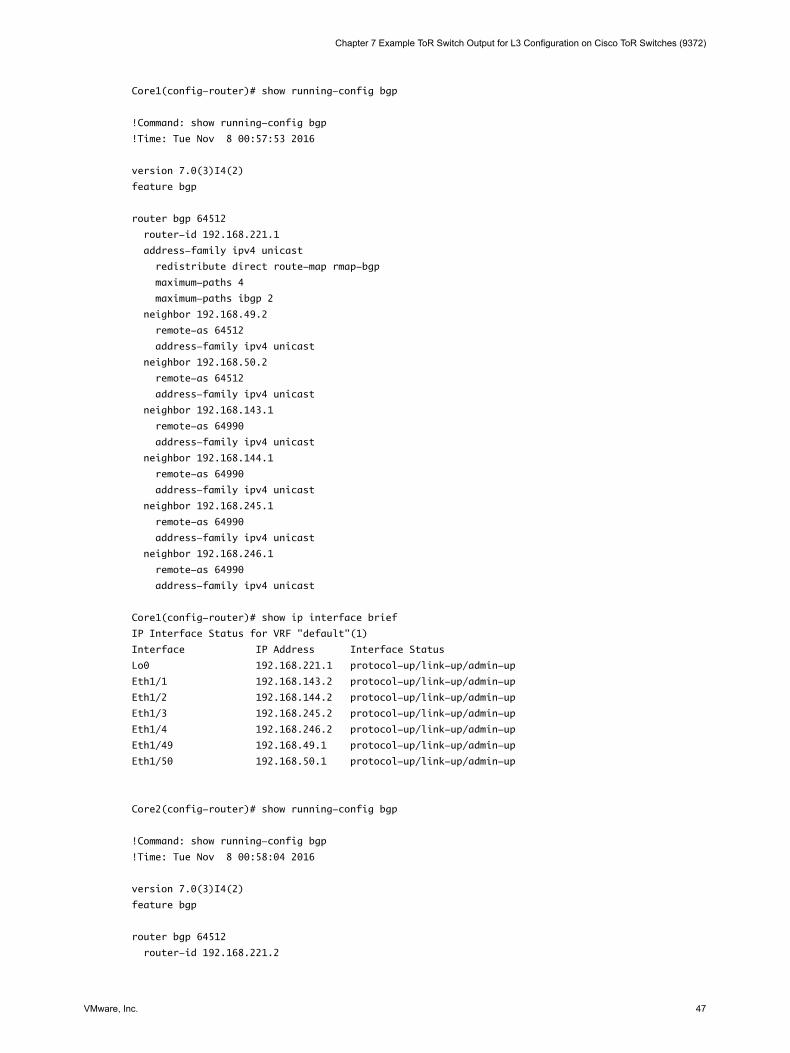
Core1(config-router)# show running-config bgp
!Command: show running-config bgp
!Time: Tue Nov 8 00:57:53 2016
version 7.0(3)I4(2)
feature bgp
router bgp 64512
router-id 192.168.221.1
address-family ipv4 unicast
redistribute direct route-map rmap-bgp
maximum-paths 4
maximum-paths ibgp 2
neighbor 192.168.49.2
remote-as 64512
address-family ipv4 unicast
neighbor 192.168.50.2
remote-as 64512
address-family ipv4 unicast
neighbor 192.168.143.1
remote-as 64990
address-family ipv4 unicast
neighbor 192.168.144.1
remote-as 64990
address-family ipv4 unicast
neighbor 192.168.245.1
remote-as 64990
address-family ipv4 unicast
neighbor 192.168.246.1
remote-as 64990
address-family ipv4 unicast
Core1(config-router)# show ip interface brief
IP Interface Status for VRF "default"(1)
Interface IP Address Interface Status
Lo0 192.168.221.1 protocol-up/link-up/admin-up
Eth1/1 192.168.143.2 protocol-up/link-up/admin-up
Eth1/2 192.168.144.2 protocol-up/link-up/admin-up
Eth1/3 192.168.245.2 protocol-up/link-up/admin-up
Eth1/4 192.168.246.2 protocol-up/link-up/admin-up
Eth1/49 192.168.49.1 protocol-up/link-up/admin-up
Eth1/50 192.168.50.1 protocol-up/link-up/admin-up
Core2(config-router)# show running-config bgp
!Command: show running-config bgp
!Time: Tue Nov 8 00:58:04 2016
version 7.0(3)I4(2)
feature bgp
router bgp 64512
router-id 192.168.221.2
Chapter 7 Example ToR Switch Output for L3 Configuration on Cisco ToR Switches (9372)
VMware, Inc. 47

address-family ipv4 unicast
redistribute direct route-map rmap-bgp
maximum-paths 4
maximum-paths ibgp 2
neighbor 192.168.49.1
remote-as 64512
address-family ipv4 unicast
neighbor 192.168.50.1
remote-as 64512
address-family ipv4 unicast
neighbor 192.168.145.1
remote-as 64990
address-family ipv4 unicast
neighbor 192.168.146.1
remote-as 64990
address-family ipv4 unicast
neighbor 192.168.243.1
remote-as 64990
address-family ipv4 unicast
neighbor 192.168.244.1
remote-as 64990
address-family ipv4 unicast
Core2(config-router)# show ip interface brief
IP Interface Status for VRF "default"(1)
Interface IP Address Interface Status
Lo0 192.168.221.2 protocol-up/link-up/admin-up
Eth1/1 192.168.243.2 protocol-up/link-up/admin-up
Eth1/2 192.168.244.2 protocol-up/link-up/admin-up
Eth1/3 192.168.145.2 protocol-up/link-up/admin-up
Eth1/4 192.168.146.2 protocol-up/link-up/admin-up
Eth1/49 192.168.49.2 protocol-up/link-up/admin-up
Eth1/50 192.168.50.2 protocol-up/link-up/admin-up
VMware Cloud Foundation Overview and Bring-Up Guide
48 VMware, Inc.

Cloud Foundation Glossary 8Term Description
add rack Configure an additional rack for a Cloud Foundation system.
additional rack Additional racks (added after the first rack) to a Cloud Foundation system.
bring-up Initial configuration of a newly deployedCloud Foundation system. .
Cloud Foundation system. Set of physical racks managed as a unit by a single SDDC Manager.
first rack First (primary) rack in the Cloud Foundation system. The management domain isdeployed on this rack.
Hardware ManagementSystem (HMS)
Manages hosts and switches in the Cloud Foundation system.
host An imaged server.
host 0 First host to be imaged by VIA. This host has the 192.168.100.50 IP address.
imaging During imaging, SDDC software is pre-configured on a physical rack.
integrated system System that combines hardware and software. Can be purchased from select VMwarepartners. The partner images the rack before sending it to the customer site.
inter-rack switches Connects individual ToR switches with each other to provide connectivity across racks.These switches are required only when you have more than one rack in yourCloud Foundation system, and are placed on the second rack.
Lifecycle Manager (LCM) Automates patching and upgrading of the software stack.
management domain Cluster of physical hosts (first fours hosts in the physical rack) that house themanagement component VMs
management host Standalone ESXi server to host the Windows jump VM used for imaging.
SDDC Manager Software component that provisions, manages, and monitors the logical and physicalresources of a Cloud Foundation system.
SDDC ManagerControllerVM
Contains the SDDC Managerservices and a shell from which command line tools can berun. This VM exposes the SDDC Manager UI.
SDDC Manager Utility VM Contains the LCM depot, backup repository containing NSX Manager and host backups,and 2nd DNS instance.
server Bare metal server in a physical rack. After imaging, it is referred to as a host.
Top of Rack (ToR) switch Connects servers within a rack through 10Gbps links to the NICs on each server. ACloud Foundation rack contains two ToR switches connected to each other.
VMware, Inc. 49
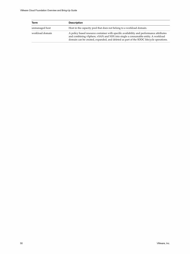
Term Description
unmanaged host Host in the capacity pool that does not belong to a workload domain.
workload domain A policy based resource container with specific availability and performance attributesand combining vSphere, vSAN and NSX into single a consumable entity. A workloaddomain can be created, expanded, and deleted as part of the SDDC lifecycle operations.
VMware Cloud Foundation Overview and Bring-Up Guide
50 VMware, Inc.

Index
Aabout the Hardware Management System
(HMS) 19about the Overview and Bring-Up Guide 5adding another rack 37another rack, adding 37architecture, Cloud Foundation 15architecture model
consolidated 18standard 17
Bbackup
copy to accessible location 35scedule 35
bootstrap additional rack 38bring-up, initial setup 28Bring-up fails, NSX fails to power on 40
Cchange password, SDDC Manager 34configuration, system 26connecting the system at your location 25
Ddata center network, connecting to 25deploying your system 23deployment, troubleshooting 39
Gglossary 5
HHardware Management System, about 19
Iintended audience 5inter-rack switches 12introducing Cloud Foundation 7
LLCM service 19
MManagement switch 12
Nnetwork topology 13
Pphysical topology 11power source, connecting to 25powering on additional racks 37pre-packaged workloads 9
RRestart HMS 40Retry NFS datastore creation 40
SSDDC Manager
about 18Bring-Up Service 19Events Engine 19LCM service 19Manager Service 19System Controller Service 19Utility VM 20
SDDC components 20servers 12setting up your system 23setup wizard 26storage topology 13system, setting up 23system configuration 26System Controller Service 19
Ttop-of-rack switches 12troubleshooting, during system setup 39
Uuse cases, VDI 10
VVDI use case 10VDI workloads 9VI use case 10VI workloads 9VIA 18Virtual Desktop Infrastructure, use case 10
VMware, Inc. 51

VMware SDDC product documentation 43
Wworkload use cases, VI 10workloads, pre-packaged 9
VMware Cloud Foundation Overview and Bring-Up Guide
52 VMware, Inc.