Embed Size (px)
Citation preview
H17731
Architecture Guide
VMware Cloud Foundation on VxRail Architecture Guide
Abstract
This guide introduces the architecture of the VMware Cloud Foundation
on VxRail solution. It describes the different components within the
solution and also acts as an aid to selecting the configuration needed for
your business requirements.
April 2019
2 VMware Cloud Foundation on VxRail Architecture Guide
Revisions
Date Description
April 2019 Initial release
The information in this publication is provided “as is.” Dell Inc. makes no representations or warranties of any kind with respect to the information in this
publication, and specifically disclaims implied warranties of merchantability or fitness for a particular purpose.
Use, copying, and distribution of any software described in this publication requires an applicable software license.
Copyright © 2019 Dell Inc. or its subsidiaries. All Rights Reserved. Dell, EMC, Dell EMC and other trademarks are trademarks of Dell Inc. or its
subsidiaries. Other trademarks may be trademarks of their respective owners. [4/15/2019] [Architecture Guide] [H17731]
3 VMware Cloud Foundation on VxRail Architecture Guide
Table of contents
Revisions............................................................................................................................................................................. 2
1 Executive Summary ..................................................................................................................................................... 5
1.1 VMware Cloud Foundation on VxRail ................................................................................................................ 5
1.2 Document purpose ............................................................................................................................................. 5
1.3 Intended audience .............................................................................................................................................. 5
2 Architecture Overview .................................................................................................................................................. 6
2.1 VxRail Manager .................................................................................................................................................. 7
2.2 SDDC Manager .................................................................................................................................................. 7
2.3 Network Virtualization ......................................................................................................................................... 7
2.4 vRealize Operations ........................................................................................................................................... 7
2.5 Logging and Analytics ........................................................................................................................................ 7
2.6 Cloud Management ............................................................................................................................................ 8
3 Workload Domain Architecture ..................................................................................................................................... 9
3.1 Physical workload domain layout ....................................................................................................................... 9
3.1.1 VxRail Hardware Options ................................................................................................................................. 11
3.2 Management Workload Domain ....................................................................................................................... 12
3.3 vCenter design.................................................................................................................................................. 13
3.4 VxRail VI Workload Domain ............................................................................................................................. 13
3.4.1 VI Workload Domain ......................................................................................................................................... 13
3.4.2 Horizon VDI Domain ......................................................................................................................................... 14
4 VxRail Virtual Network Architecture ........................................................................................................................... 16
4.1 Virtual Switches ................................................................................................................................................ 16
4.2 NIC Teaming ..................................................................................................................................................... 17
5 NSX Functional Components ..................................................................................................................................... 18
5.1 NSX Manager ................................................................................................................................................... 18
5.2 NSX Controllers ................................................................................................................................................ 18
5.3 NSX vSwitch ..................................................................................................................................................... 18
5.4 VXLAN and VTEPs ........................................................................................................................................... 19
5.5 Logical switching............................................................................................................................................... 20
5.6 Distributed logical routing ................................................................................................................................. 20
5.7 Edge services gateway (ESG) .......................................................................................................................... 21
5.8 Distributed firewall (DFW) ................................................................................................................................. 21
6 NSX Cluster Design ................................................................................................................................................... 22
6.1 NSX physical network requirements................................................................................................................. 22
6.2 NSX deployment in workload domain............................................................................................................... 22
4 VMware Cloud Foundation on VxRail Architecture Guide
6.3 Transport Zone Design ..................................................................................................................................... 23
6.4 Logical switch control plane replication mode .................................................................................................. 24
6.5 NSX virtual routing design ................................................................................................................................ 24
7 Physical network design considerations .................................................................................................................... 27
7.1 Traditional 3-tier (access/core/aggregation) ..................................................................................................... 27
7.2 Leaf and Spine layer 3 fabric ............................................................................................................................ 28
7.3 Multi-rack design considerations ...................................................................................................................... 29
7.3.1 VxRail multi-rack cluster ................................................................................................................................... 29
7.4 Physical network interfaces .............................................................................................................................. 31
8 Multi-site design considerations ................................................................................................................................. 32
8.1 Stretched cluster ............................................................................................................................................... 32
8.1.1 Management workload component placement ................................................................................................. 33
8.1.2 Witness traffic separation (WTS) ...................................................................................................................... 34
8.1.3 NSX stretched-cluster routing design ............................................................................................................... 35
8.2 Dual region with disaster recovery ................................................................................................................... 36
8.2.1 SSO Considerations ......................................................................................................................................... 37
8.2.2 NSX Dual-Region Routing Design .................................................................................................................... 38
9 Operations Management Architecture ....................................................................................................................... 39
9.1 VxRail vCenter UI ............................................................................................................................................. 39
9.2 vRealize Operations ......................................................................................................................................... 39
9.3 vRealize Log Insight ......................................................................................................................................... 40
10 Lifecycle Management ............................................................................................................................................... 41
10.1 vRealize Suite Lifecycle Manager .................................................................................................................... 42
11 Cloud Management Architecture ................................................................................................................................ 43
5 VMware Cloud Foundation on VxRail Architecture Guide
1 Executive Summary
1.1 VMware Cloud Foundation on VxRail VMware Cloud Foundation on VxRail is a Dell EMC and VMware jointly engineered integrated solution with
features that simplify, streamline, and automate the operations of your entire SDDC from Day 0 through Day
2. The new platform delivers a set of software-defined services for compute (with vSphere and vCenter),
storage (with vSAN), networking (with NSX), security, and cloud management (with vRealize Suite) in both
private and public environments, making it the operational hub for your hybrid cloud.
VMware Cloud Foundation on VxRail provides the simplest path to the hybrid cloud through a fully integrated
hybrid cloud platform that leverages native VxRail hardware and software capabilities and other VxRail unique
integrations (such as vCenter plugins and Dell EMC networking) working together to deliver a new turnkey
hybrid cloud user experience with full-stack integrity. Full-stack integrity means you get both HCI
infrastructure layer and cloud software stack in one complete automated lifecycle turnkey experience.
1.2 Document purpose This guide introduces the architecture of the VMware Cloud Foundation on VxRail solution It describes the
different components within the solution and also acts as an aid to selecting the configuration needed for your
business requirements.
1.3 Intended audience This architecture guide is intended for executives, managers, cloud architects, network architects, and
technical sales engineers interested in designing or deploying a Software Defined Datacenter (SDDC) or
Hybrid Cloud Platform to meet the needs or the business requirements. The readers should be familiar with
the VMware vSphere, NSX, vSAN and vRealize product suites in addition to general network architecture
concepts.
6 VMware Cloud Foundation on VxRail Architecture Guide
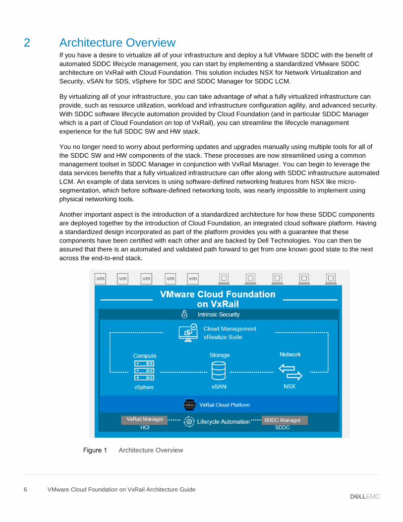
2 Architecture Overview If you have a desire to virtualize all of your infrastructure and deploy a full VMware SDDC with the benefit of
automated SDDC lifecycle management, you can start by implementing a standardized VMware SDDC
architecture on VxRail with Cloud Foundation. This solution includes NSX for Network Virtualization and
Security, vSAN for SDS, vSphere for SDC and SDDC Manager for SDDC LCM.
By virtualizing all of your infrastructure, you can take advantage of what a fully virtualized infrastructure can
provide, such as resource utilization, workload and infrastructure configuration agility, and advanced security.
With SDDC software lifecycle automation provided by Cloud Foundation (and in particular SDDC Manager
which is a part of Cloud Foundation on top of VxRail), you can streamline the lifecycle management
experience for the full SDDC SW and HW stack.
You no longer need to worry about performing updates and upgrades manually using multiple tools for all of
the SDDC SW and HW components of the stack. These processes are now streamlined using a common
management toolset in SDDC Manager in conjunction with VxRail Manager. You can begin to leverage the
data services benefits that a fully virtualized infrastructure can offer along with SDDC infrastructure automated
LCM. An example of data services is using software-defined networking features from NSX like micro-
segmentation, which before software-defined networking tools, was nearly impossible to implement using
physical networking tools.
Another important aspect is the introduction of a standardized architecture for how these SDDC components
are deployed together by the introduction of Cloud Foundation, an integrated cloud software platform. Having
a standardized design incorporated as part of the platform provides you with a guarantee that these
components have been certified with each other and are backed by Dell Technologies. You can then be
assured that there is an automated and validated path forward to get from one known good state to the next
across the end-to-end stack.
Architecture Overview
7 VMware Cloud Foundation on VxRail Architecture Guide
2.1 VxRail Manager VMware Cloud Foundation on VxRail uses VxRail Manager to deploy and configure vSphere clusters
powered by vSAN. It is also used to execute the lifecycle management of ESXi, vSAN and HW firmware using
a fully integrated and seamless SDDC Manager orchestrated process. It monitors the health of hardware
components and provides remote service support. This level of integration provides a truly unique turnkey
hybrid cloud experience not available on any other infrastructure.
VxRail Manager provides the glue for the HCI hardware and software and is all lifecycle managed together.
By focusing on the glue and automation across the deployment, updating, monitoring, and maintenance
phases of product lifecycle, VxRail Manager delivers value by removing the need for heavy operational
staffing. This improves operational efficiency, reduces LCM risk, and significantly changes the focus of staff
by providing value back to the business rather than expending time on maintaining the infrastructure.
2.2 SDDC Manager SDDC Manager orchestrates the deployment, configuration, and lifecycle management (LCM) of vCenter,
NSX, and vRealize suite above the ESXi and vSAN layers of VxRail. It unifies multiple VxRail clusters as
workload domains or as multi-cluster workload domains. It creates the stretched cluster configuration for a
dual-availability zone (AZ) workload domain.
2.3 Network Virtualization VMware NSX Data Center is the network virtualization and security platform that enables the virtual cloud
network. It’s a software-defined approach to networking that extends across data centers, clouds, endpoints,
and edge locations. With NSX Data Center, network functions—including switching, routing, firewalling, and
load balancing—are brought closer to the application and distributed across the environment. Similar to the
operational model of virtual machines, networks can be provisioned and managed independent of underlying
hardware.
NSX Data Center reproduces the entire network model in software, enabling any network topology—from
simple to complex multitier networks—to be created and provisioned in seconds. Users can create multiple
virtual networks with diverse requirements, leveraging a combination of the services offered via NSX including
micro-segmentation or from a broad ecosystem of third-party integrations ranging from next-generation
firewalls to performance management solutions to build inherently more agile and secure environments.
These services can then be extended to a number of endpoints within and across clouds.
2.4 vRealize Operations The vRealize Operation management components allow centralized monitoring of and logging data about the other solutions in the SDDC. The physical infrastructure, virtual infrastructure and tenant workloads are monitored in real-time, collecting information for intelligent and dynamic operational management.
2.5 Logging and Analytics Another component of the VMware SDDC is VMware vRealize Log lnsight™. It delivers heterogeneous and
highly scalable log management with intuitive, actionable dashboards, sophisticated analytics, and broad
third-party extensibility, providing deep operational visibility and faster troubleshooting.
8 VMware Cloud Foundation on VxRail Architecture Guide
2.6 Cloud Management The Cloud Management platform (CMP) is the main consumption portal for the software-defined data center
(SDDC). You use vRealize Automation to author, administer, and consume VM templates and blueprints. As
an integral component of VMware Cloud Foundation, vRealize Automation provides a unified service catalog
that gives IT or end-users the ability to select and execute requests to instantiate specific services.
9 VMware Cloud Foundation on VxRail Architecture Guide
3 Workload Domain Architecture A workload domain consists of one or more Dell EMC 14G VxRail clusters that are managed by one vCenter
Server instance and network equipment for connection to the data center. Workload domains are connected
to a network core that distributes data between them. Workload domains can include different combinations of
VxRail clusters and network equipment which can be set up with varying levels of hardware redundancy.
From the VxRail clusters, you can organize separate pools of capacity into workload domains, each with its
own set of specified CPU, memory and storage requirements to support various workloads types such as
Horizon or business-critical apps like Oracle databases, etc. As new VxRail physical capacity is added, it will
be added by the SDDC Manager and be made available for consumption as part of a workload domain.
There are three types of workload domains that can be deployed:
• a Virtual Infrastructure (VI) workload domain, also known as a tenant workload domain
• a Horizon workload domain, and
• a special workload domain called the Management workload domain (Mgmt WLD).
We will look at each type of workload domain in more detail in the next section, but let’s first look at the
physical layout of a workload domain.
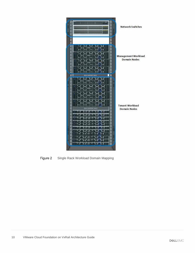
3.1 Physical workload domain layout A workload domain represents a logical boundary of functionality, managed by a single vCenter server
instance. Although a workload domain usually spans one rack, you can aggregate multiple workload domains
in a single rack in smaller setups, or in larger configurations, workload domains can span racks.
The following figure shows how one rack can be used to host two different workload domains, the
management workload domain and one tenant workload domain. Note that a tenant workload domain can
consist of one or more clusters, this will be discussed later.
10 VMware Cloud Foundation on VxRail Architecture Guide
Single Rack Workload Domain Mapping
11 VMware Cloud Foundation on VxRail Architecture Guide
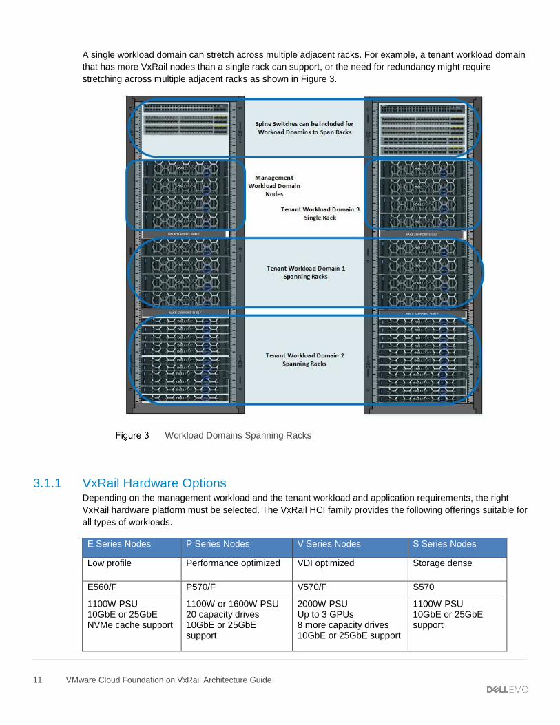
A single workload domain can stretch across multiple adjacent racks. For example, a tenant workload domain
that has more VxRail nodes than a single rack can support, or the need for redundancy might require
stretching across multiple adjacent racks as shown in Figure 3.
Workload Domains Spanning Racks
3.1.1 VxRail Hardware Options Depending on the management workload and the tenant workload and application requirements, the right
VxRail hardware platform must be selected. The VxRail HCI family provides the following offerings suitable for
all types of workloads.
E Series Nodes P Series Nodes V Series Nodes S Series Nodes
Low profile
Performance optimized VDI optimized
Storage dense
E560/F P570/F V570/F S570
1100W PSU 10GbE or 25GbE NVMe cache support
1100W or 1600W PSU 20 capacity drives 10GbE or 25GbE support
2000W PSU Up to 3 GPUs 8 more capacity drives 10GbE or 25GbE support
1100W PSU 10GbE or 25GbE support
12 VMware Cloud Foundation on VxRail Architecture Guide
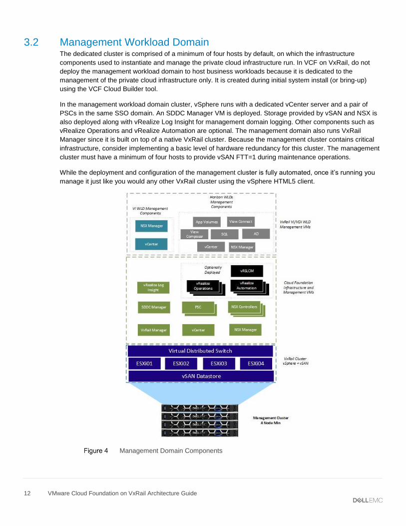
3.2 Management Workload Domain The dedicated cluster is comprised of a minimum of four hosts by default, on which the infrastructure
components used to instantiate and manage the private cloud infrastructure run. In VCF on VxRail, do not
deploy the management workload domain to host business workloads because it is dedicated to the
management of the private cloud infrastructure only. It is created during initial system install (or bring-up)
using the VCF Cloud Builder tool.
In the management workload domain cluster, vSphere runs with a dedicated vCenter server and a pair of
PSCs in the same SSO domain. An SDDC Manager VM is deployed. Storage provided by vSAN and NSX is
also deployed along with vRealize Log Insight for management domain logging. Other components such as
vRealize Operations and vRealize Automation are optional. The management domain also runs VxRail
Manager since it is built on top of a native VxRail cluster. Because the management cluster contains critical
infrastructure, consider implementing a basic level of hardware redundancy for this cluster. The management
cluster must have a minimum of four hosts to provide vSAN FTT=1 during maintenance operations.
While the deployment and configuration of the management cluster is fully automated, once it’s running you
manage it just like you would any other VxRail cluster using the vSphere HTML5 client.
Management Domain Components
13 VMware Cloud Foundation on VxRail Architecture Guide
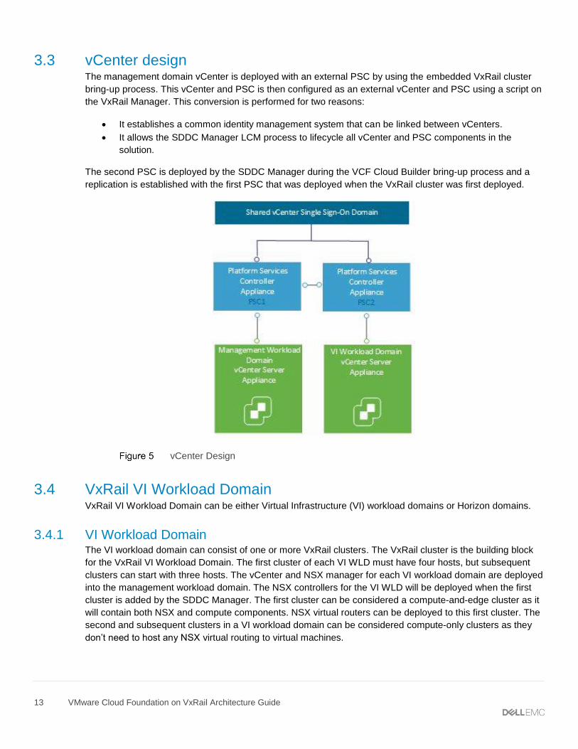
3.3 vCenter design The management domain vCenter is deployed with an external PSC by using the embedded VxRail cluster
bring-up process. This vCenter and PSC is then configured as an external vCenter and PSC using a script on
the VxRail Manager. This conversion is performed for two reasons:
• It establishes a common identity management system that can be linked between vCenters.
• It allows the SDDC Manager LCM process to lifecycle all vCenter and PSC components in the
solution.
The second PSC is deployed by the SDDC Manager during the VCF Cloud Builder bring-up process and a
replication is established with the first PSC that was deployed when the VxRail cluster was first deployed.
vCenter Design
3.4 VxRail VI Workload Domain VxRail VI Workload Domain can be either Virtual Infrastructure (VI) workload domains or Horizon domains.
3.4.1 VI Workload Domain The VI workload domain can consist of one or more VxRail clusters. The VxRail cluster is the building block
for the VxRail VI Workload Domain. The first cluster of each VI WLD must have four hosts, but subsequent
clusters can start with three hosts. The vCenter and NSX manager for each VI workload domain are deployed
into the management workload domain. The NSX controllers for the VI WLD will be deployed when the first
cluster is added by the SDDC Manager. The first cluster can be considered a compute-and-edge cluster as it
will contain both NSX and compute components. NSX virtual routers can be deployed to this first cluster. The
second and subsequent clusters in a VI workload domain can be considered compute-only clusters as they
don’t need to host any NSX virtual routing to virtual machines.
14 VMware Cloud Foundation on VxRail Architecture Guide
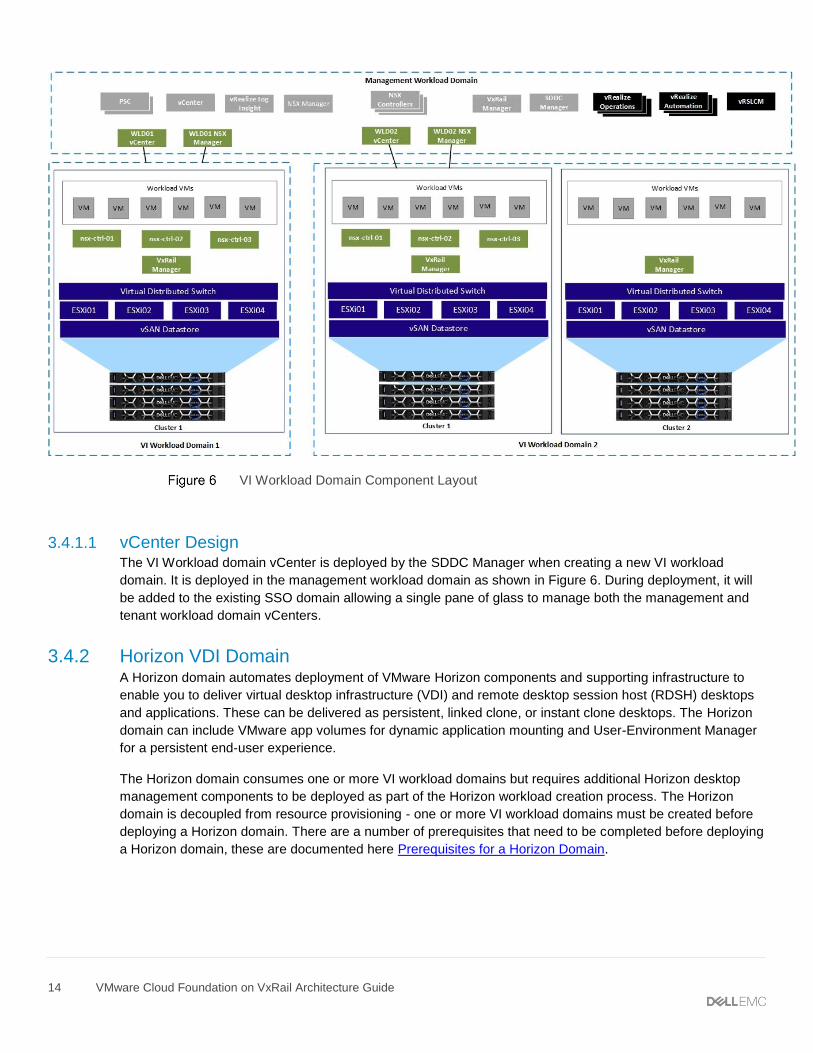
VI Workload Domain Component Layout
3.4.1.1 vCenter Design The VI Workload domain vCenter is deployed by the SDDC Manager when creating a new VI workload
domain. It is deployed in the management workload domain as shown in Figure 6. During deployment, it will
be added to the existing SSO domain allowing a single pane of glass to manage both the management and
tenant workload domain vCenters.
3.4.2 Horizon VDI Domain A Horizon domain automates deployment of VMware Horizon components and supporting infrastructure to
enable you to deliver virtual desktop infrastructure (VDI) and remote desktop session host (RDSH) desktops
and applications. These can be delivered as persistent, linked clone, or instant clone desktops. The Horizon
domain can include VMware app volumes for dynamic application mounting and User-Environment Manager
for a persistent end-user experience.
The Horizon domain consumes one or more VI workload domains but requires additional Horizon desktop
management components to be deployed as part of the Horizon workload creation process. The Horizon
domain is decoupled from resource provisioning - one or more VI workload domains must be created before
deploying a Horizon domain. There are a number of prerequisites that need to be completed before deploying
a Horizon domain, these are documented here Prerequisites for a Horizon Domain.
15 VMware Cloud Foundation on VxRail Architecture Guide
During the Horizon domain deployment, one to three connection servers and a corresponding load balancer is
deployed. In addition, you can choose the optional components that you want to deploy:
• Composer Server
• App Volumes
• User Environment Manager
• Unified Access Gateway
The Horizon domain is based on the Horizon reference architecture, which uses Pod Block architecture to
enable you to scale as your use cases grow. For more information about the architecture and number of
supported virtual machines, refer to the Horizon 7 Pod and Block section in the VMware Workspace ONE and
VMware Horizon 7 Enterprise Edition On-premises Reference Architecture document.
16 VMware Cloud Foundation on VxRail Architecture Guide
4 VxRail Virtual Network Architecture The solution uses the network virtualization inherent in vSphere for deployment and operations of the VxRail
cluster. VMware Cloud Foundation depends on this underlying vSphere network to support a comprehensive
virtualized network using NSX.
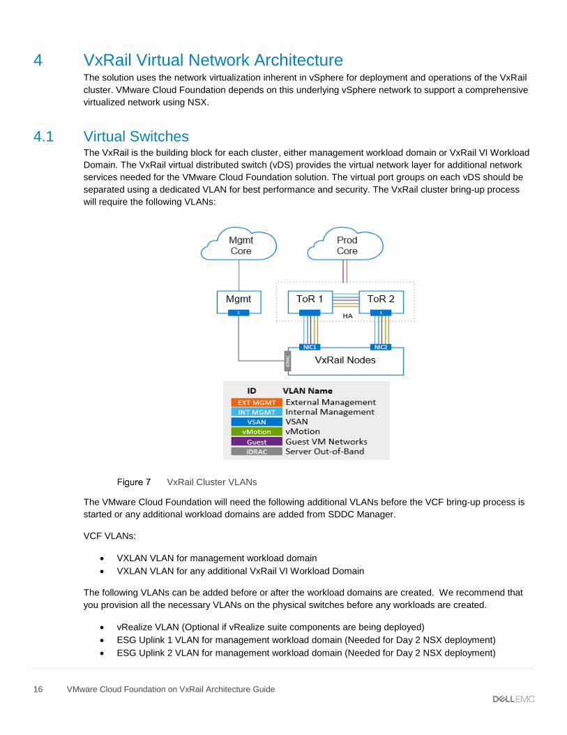
4.1 Virtual Switches The VxRail is the building block for each cluster, either management workload domain or VxRail VI Workload
Domain. The VxRail virtual distributed switch (vDS) provides the virtual network layer for additional network
services needed for the VMware Cloud Foundation solution. The virtual port groups on each vDS should be
separated using a dedicated VLAN for best performance and security. The VxRail cluster bring-up process
will require the following VLANs:
VxRail Cluster VLANs
The VMware Cloud Foundation will need the following additional VLANs before the VCF bring-up process is
started or any additional workload domains are added from SDDC Manager.
VCF VLANs:
• VXLAN VLAN for management workload domain
• VXLAN VLAN for any additional VxRail VI Workload Domain
The following VLANs can be added before or after the workload domains are created. We recommend that
you provision all the necessary VLANs on the physical switches before any workloads are created.
• vRealize VLAN (Optional if vRealize suite components are being deployed)
• ESG Uplink 1 VLAN for management workload domain (Needed for Day 2 NSX deployment)
• ESG Uplink 2 VLAN for management workload domain (Needed for Day 2 NSX deployment)
17 VMware Cloud Foundation on VxRail Architecture Guide
• ESG Uplink 1 VLAN for tenant workload domain 1 (Needed for Day 2 NSX deployment)
• ESG Uplink 2 VLAN for tenant workload domain 1 (Needed for Day 2 NSX deployment)
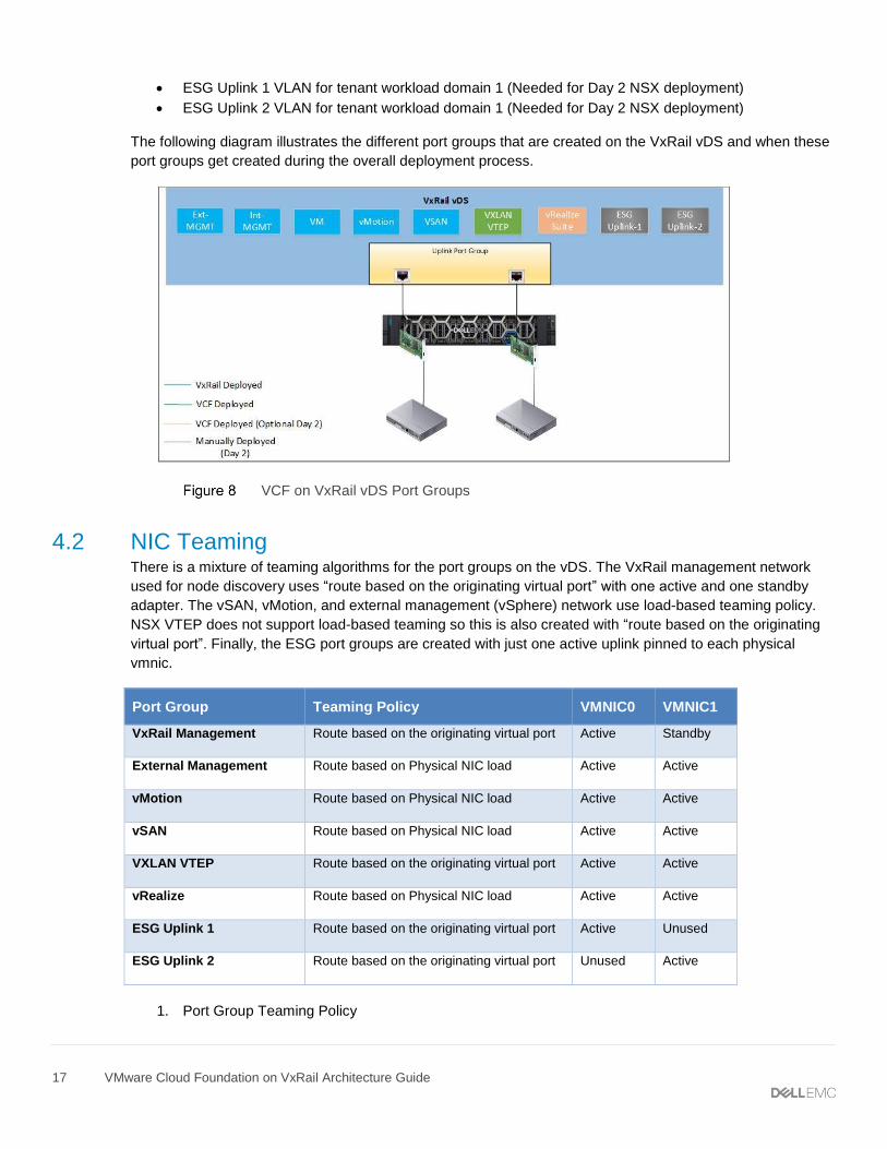
The following diagram illustrates the different port groups that are created on the VxRail vDS and when these
port groups get created during the overall deployment process.
VCF on VxRail vDS Port Groups
4.2 NIC Teaming There is a mixture of teaming algorithms for the port groups on the vDS. The VxRail management network
used for node discovery uses “route based on the originating virtual port” with one active and one standby
adapter. The vSAN, vMotion, and external management (vSphere) network use load-based teaming policy.
NSX VTEP does not support load-based teaming so this is also created with “route based on the originating
virtual port”. Finally, the ESG port groups are created with just one active uplink pinned to each physical
vmnic.
Port Group Teaming Policy VMNIC0 VMNIC1
VxRail Management Route based on the originating virtual port Active Standby
External Management Route based on Physical NIC load Active Active
vMotion Route based on Physical NIC load Active Active
vSAN Route based on Physical NIC load Active Active
VXLAN VTEP Route based on the originating virtual port Active Active
vRealize Route based on Physical NIC load Active Active
ESG Uplink 1 Route based on the originating virtual port Active Unused
ESG Uplink 2 Route based on the originating virtual port Unused Active
1. Port Group Teaming Policy
18 VMware Cloud Foundation on VxRail Architecture Guide
5 NSX Functional Components The foundation of the Network virtualization layer is NSX. This provides a software-defined networking
approach that delivers layer 2 to layer 7 networking services (e.g., switching, routing, firewalling, and load
balancing) in software. These services can then be programmatically assembled in any arbitrary combination,
producing unique, isolated virtual networks in a matter of seconds.
5.1 NSX Manager The NSX Manager is responsible for the deployment of the controller clusters and ESXi host preparation. The
host preparation process installs various vSphere installation bundles (VIBs) to enable VXLAN, distributed
routing, distributed firewall and a user world agent for control plane communications. The NSX Manager is
also responsible for the deployment and configuration of the NSX Edge services gateways and associated
network services (load balancing, firewalling, NAT, etc.). It provides the single point of configuration and the
REST API entry-points for NSX in a vSphere environment.
The NSX Manager also ensures security of the control plane communication of the NSX architecture. It
creates self-signed certificates for the nodes of the controller cluster and ESXi hosts that should be allowed to
join the NSX domain. Each workload domain has an NSX Manager as part of the VMware Cloud Foundation
on VxRail solution.
5.2 NSX Controllers The controller cluster in the NSX platform is the control plane component that manages the hypervisor
switching and routing modules. The controller cluster consists of controller nodes that manage specific logical
switches and includes three nodes that are clustered for scale-out and high-availability. The NSX Controllers
are required for each workload domain, including management and any additional VxRail VI Workload
Domain.
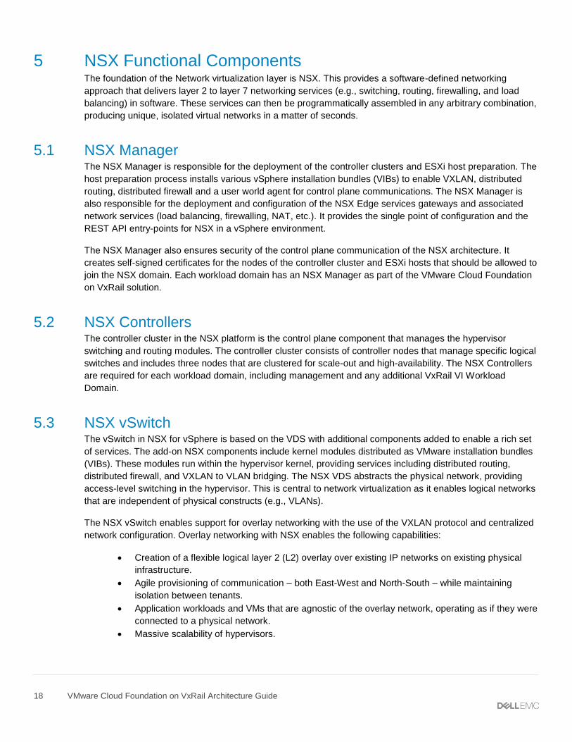
5.3 NSX vSwitch The vSwitch in NSX for vSphere is based on the VDS with additional components added to enable a rich set
of services. The add-on NSX components include kernel modules distributed as VMware installation bundles
(VIBs). These modules run within the hypervisor kernel, providing services including distributed routing,
distributed firewall, and VXLAN to VLAN bridging. The NSX VDS abstracts the physical network, providing
access-level switching in the hypervisor. This is central to network virtualization as it enables logical networks
that are independent of physical constructs (e.g., VLANs).
The NSX vSwitch enables support for overlay networking with the use of the VXLAN protocol and centralized
network configuration. Overlay networking with NSX enables the following capabilities:
• Creation of a flexible logical layer 2 (L2) overlay over existing IP networks on existing physical
infrastructure.
• Agile provisioning of communication – both East-West and North-South – while maintaining
isolation between tenants.
• Application workloads and VMs that are agnostic of the overlay network, operating as if they were
connected to a physical network.
• Massive scalability of hypervisors.
19 VMware Cloud Foundation on VxRail Architecture Guide
NSX vSwitch Data Plane Components
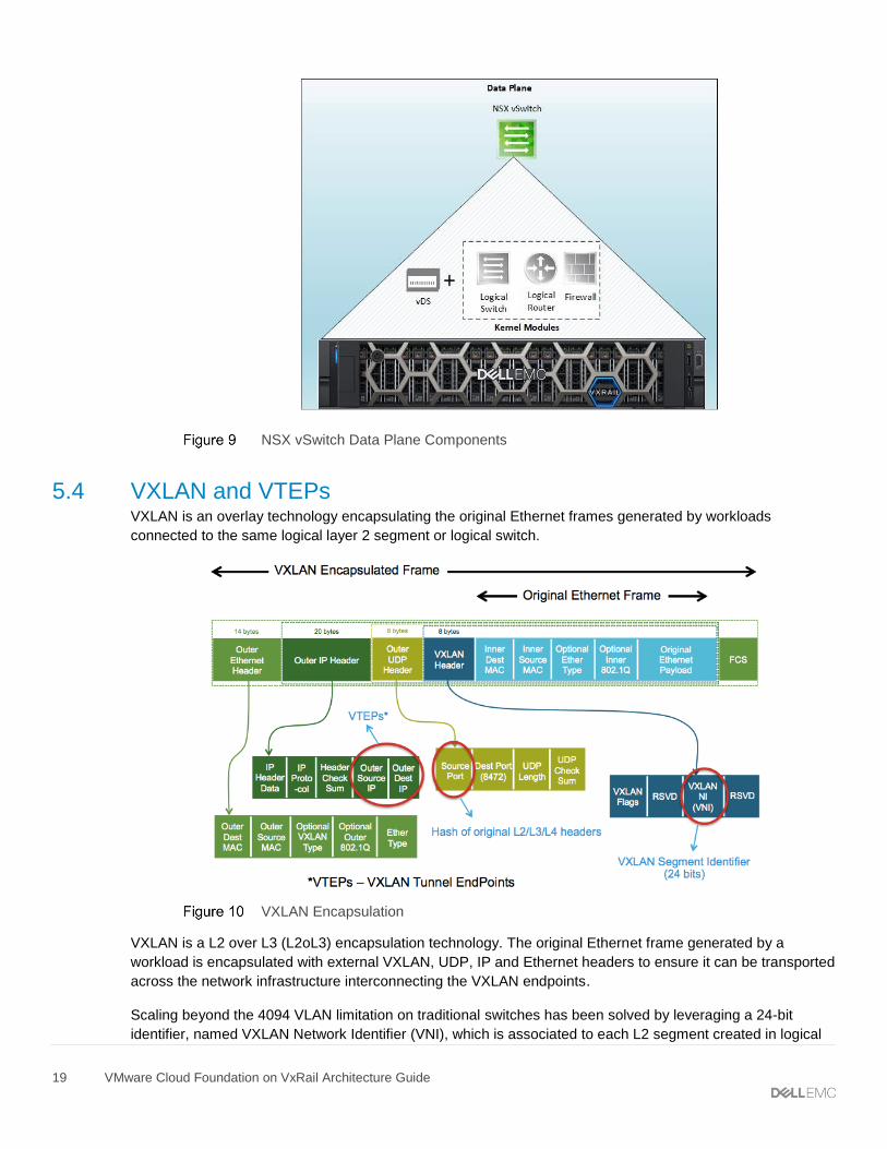
5.4 VXLAN and VTEPs VXLAN is an overlay technology encapsulating the original Ethernet frames generated by workloads
connected to the same logical layer 2 segment or logical switch.
VXLAN Encapsulation
VXLAN is a L2 over L3 (L2oL3) encapsulation technology. The original Ethernet frame generated by a
workload is encapsulated with external VXLAN, UDP, IP and Ethernet headers to ensure it can be transported
across the network infrastructure interconnecting the VXLAN endpoints.
Scaling beyond the 4094 VLAN limitation on traditional switches has been solved by leveraging a 24-bit
identifier, named VXLAN Network Identifier (VNI), which is associated to each L2 segment created in logical
20 VMware Cloud Foundation on VxRail Architecture Guide
space. This value is carried inside the VXLAN header and is normally associated to an IP subnet, similarly to
what traditionally happens with VLANs. Intra-IP subnet communication occurs between devices connected to
the same virtual network/logical switch.
VXLAN tunnel endpoints (VTEPs) are created within the vSphere distributed switch to which the ESXi hosts
that are prepared for NSX for vSphere are connected. VTEPs are responsible for encapsulating VXLAN traffic
as frames in UDP packets and for the corresponding decapsulation. VTEPs are essentially VMkernel ports
with IP addresses and are used both to exchange packets with other VTEPs and to join IP multicast groups
via Internet Group Membership Protocol (IGMP).
5.5 Logical switching Logical switching enables extension of a L2 segment / IP subnet anywhere in the fabric independent of the
physical network design. The logical switching capability in the NSX platform provides the ability to deploy
isolated logical L2 networks with the same flexibility and agility that exists for virtual machines. Endpoints,
both virtual and physical, can connect to logical segments and establish connectivity independently from their
physical location in the data center network.
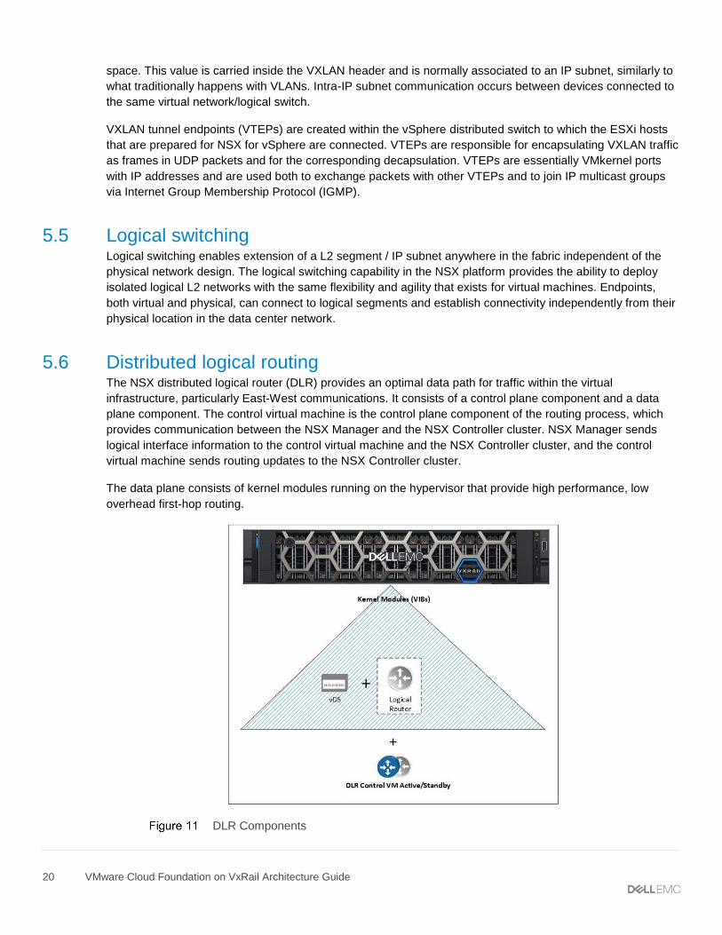
5.6 Distributed logical routing The NSX distributed logical router (DLR) provides an optimal data path for traffic within the virtual
infrastructure, particularly East-West communications. It consists of a control plane component and a data
plane component. The control virtual machine is the control plane component of the routing process, which
provides communication between the NSX Manager and the NSX Controller cluster. NSX Manager sends
logical interface information to the control virtual machine and the NSX Controller cluster, and the control
virtual machine sends routing updates to the NSX Controller cluster.
The data plane consists of kernel modules running on the hypervisor that provide high performance, low
overhead first-hop routing.
DLR Components
21 VMware Cloud Foundation on VxRail Architecture Guide
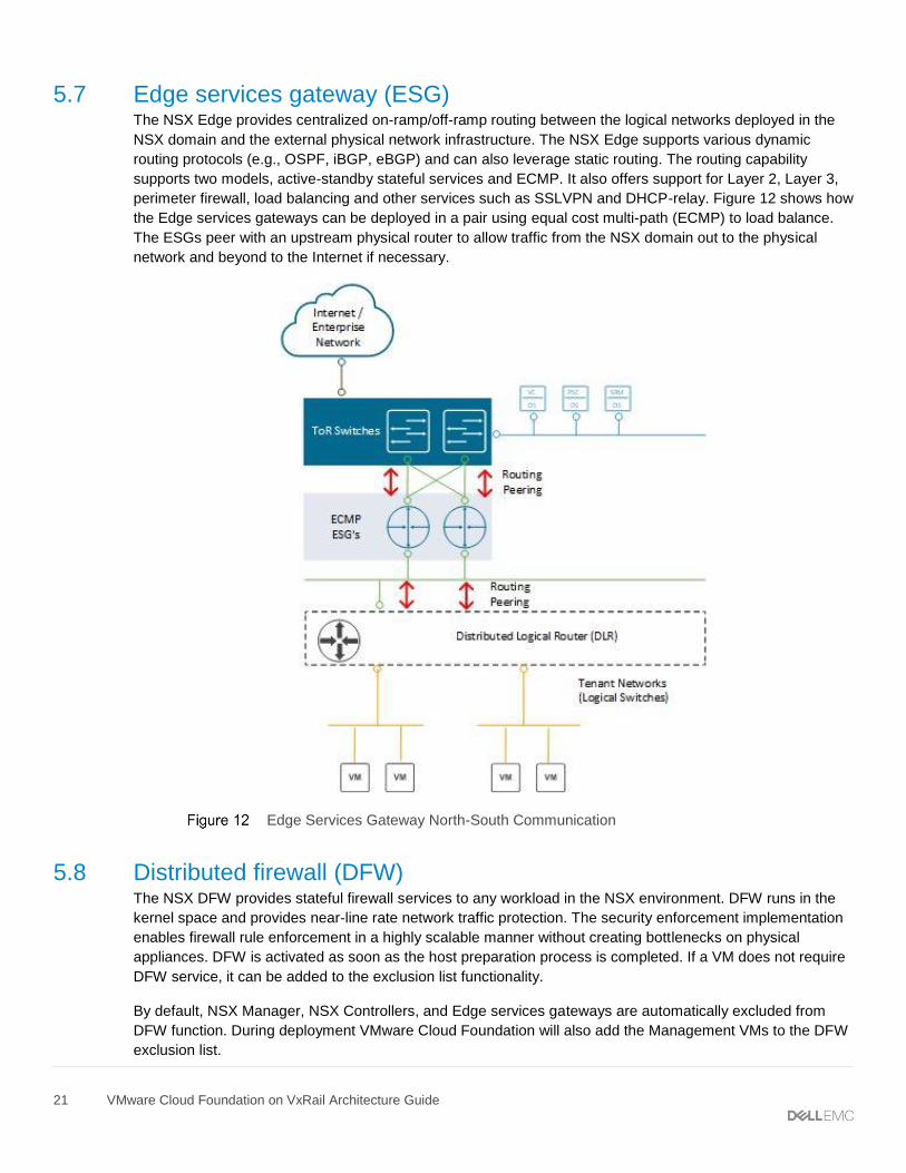
5.7 Edge services gateway (ESG) The NSX Edge provides centralized on-ramp/off-ramp routing between the logical networks deployed in the
NSX domain and the external physical network infrastructure. The NSX Edge supports various dynamic
routing protocols (e.g., OSPF, iBGP, eBGP) and can also leverage static routing. The routing capability
supports two models, active-standby stateful services and ECMP. It also offers support for Layer 2, Layer 3,
perimeter firewall, load balancing and other services such as SSLVPN and DHCP-relay. Figure 12 shows how
the Edge services gateways can be deployed in a pair using equal cost multi-path (ECMP) to load balance.
The ESGs peer with an upstream physical router to allow traffic from the NSX domain out to the physical
network and beyond to the Internet if necessary.
Edge Services Gateway North-South Communication
5.8 Distributed firewall (DFW) The NSX DFW provides stateful firewall services to any workload in the NSX environment. DFW runs in the
kernel space and provides near-line rate network traffic protection. The security enforcement implementation
enables firewall rule enforcement in a highly scalable manner without creating bottlenecks on physical
appliances. DFW is activated as soon as the host preparation process is completed. If a VM does not require
DFW service, it can be added to the exclusion list functionality.
By default, NSX Manager, NSX Controllers, and Edge services gateways are automatically excluded from
DFW function. During deployment VMware Cloud Foundation will also add the Management VMs to the DFW
exclusion list.
22 VMware Cloud Foundation on VxRail Architecture Guide
6 NSX Cluster Design The initial deployment of the SDDC management or workload domain will depend on the supporting physical
network and underlying VxRail vSphere virtual network to establish basic network connectivity for domain
management, and establish the foundation for a future fully virtualized network with NSX. At this stage,
network design considerations are applied to the domain to enable a fully virtualized network using NSX.
6.1 NSX physical network requirements NSX has the following external network requirements that must be met before the VMware Cloud Foundation
on VxRail solution can be deployed.
• MTU 1600 or greater for VXLAN traffic (For Multi-site ensure MTU across ISL)
• IGMP Snooping for each VXLAN VLAN on the first hop switches
• IGMP querier must be enabled on the connected router or Layer 3 switch.
• VLAN for Management workload domain VXLAN created on the switches
• VLAN for VI workload domain VXLAN created on the switches
• DHCP must be configured for each VXLAN VLAN to assign the VTEPs IP.
• Layer 3 license requirement for peering with ESGs
• BGP configured for each router peering with an ESG
• Optional vRealize VLAN
• Two Uplink VLANs for ESGs in Management workload domain
• Two Uplink VLANs for ESGs in each WLD
6.2 NSX deployment in workload domain The management workload domain cluster and each workload domain will deploy NSX components during
the deployment process. The SDDC Manager is responsible for deploying NSX components onto the VI
workload domain clusters. The following steps are executed by the VCF Cloud Builder during the
management workload domain bring-up process.
1. Deploy NSX Manager in management workload domain cluster.
2. Register NSX Manager with PSC01.
3. Register NSX Manager with management workload domain VC.
4. Install license for NSX.
5. Deploy 3 NSX controllers to management workload domain cluster.
6. Create Anti-Affinity rules for controllers.
7. Create VXLAN segment ID range.
8. Create a global transport zone.
9. Add cluster to transport zone.
10. Install NSX VIBs (host prep).
11. Create VXLAN port group and VTEPs.
Note: A multicast IP range for VXLAN hybrid replication must be configured manually after the VXLAN
configuration is completed for any workload domain.
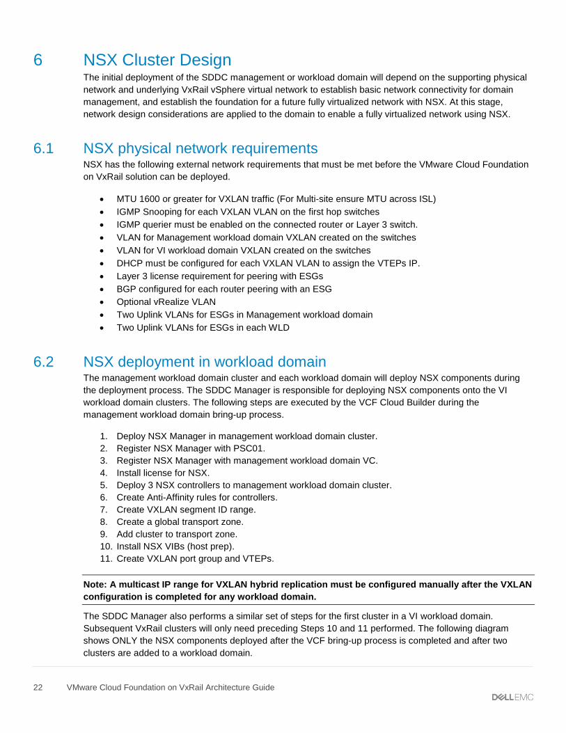
The SDDC Manager also performs a similar set of steps for the first cluster in a VI workload domain.
Subsequent VxRail clusters will only need preceding Steps 10 and 11 performed. The following diagram
shows ONLY the NSX components deployed after the VCF bring-up process is completed and after two
clusters are added to a workload domain.
23 VMware Cloud Foundation on VxRail Architecture Guide
VMware Cloud Foundation for VxRail NSX Component Layout
6.3 Transport Zone Design A transport zone controls which hosts a logical switch can reach and can span one or more vSphere clusters.
Transport zones dictate which clusters and, therefore, which VMs can participate in the use of a layer 2
network. The Management Workload domain cluster will have its own transport zone created during the VCF
bring-up process. When creating a VI workload domain, the SDDC Manager creates the transport zone while
the first cluster is added to the VI workload domain. Subsequent cluster will be added to the transport zone.
This allows VMs in a workload domain on the same logical switch to span clusters. This, this can be useful
when designing three-tier applications using a flat layer 2 but keeping different workloads on different clusters.
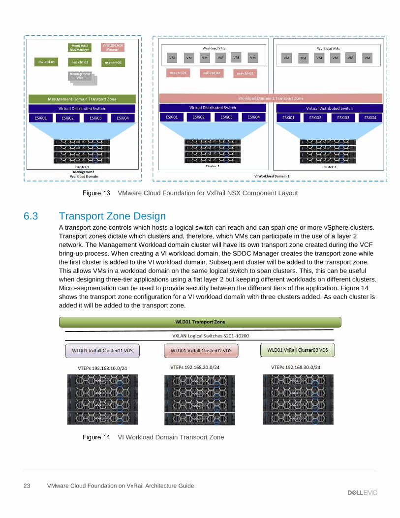
Micro-segmentation can be used to provide security between the different tiers of the application. Figure 14
shows the transport zone configuration for a VI workload domain with three clusters added. As each cluster is
added it will be added to the transport zone.
VI Workload Domain Transport Zone
24 VMware Cloud Foundation on VxRail Architecture Guide
6.4 Logical switch control plane replication mode The control plane decouples connectivity in the logical space from the physical network infrastructure and
handles the broadcast, unknown unicast, and multicast (BUM) traffic within the logical switches. The control
plane is on top of the transport zone and is inherited by all logical switches that are created within it. VMware
Cloud Foundation on VxRail uses the hybrid replication mode to send BUM traffic. This mode is an optimized
version of the unicast mode where local traffic replication for the subnet is offloaded to the physical network.
Hybrid mode requires IGMP snooping on the first-hop switch and access to an IGMP querier in each VTEP
subnet or VLAN. Using VLANs for the management domain VXLAN VLAN that are different than the VLANs
used for workload domains is recommended to completely isolate the management and tenant traffic in the
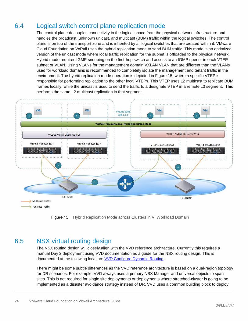
environment. The hybrid replication mode operation is depicted in Figure 15, where a specific VTEP is
responsible for performing replication to the other local VTEPs. This VTEP uses L2 multicast to replicate BUM
frames locally, while the unicast is used to send the traffic to a designate VTEP in a remote L3 segment. This
performs the same L2 multicast replication in that segment.
Hybrid Replication Mode across Clusters in VI Workload Domain
6.5 NSX virtual routing design The NSX routing design will closely align with the VVD reference architecture. Currently this requires a
manual Day 2 deployment using VVD documentation as a guide for the NSX routing design. This is
documented at the following location: VVD Configure Dynamic Routing.
There might be some subtle differences as the VVD reference architecture is based on a dual-region topology
for DR scenarios. For example, VVD always uses a primary NSX Manager and universal objects to span
sites. This is not required for single site deployments or deployments where stretched-cluster is going to be
implemented as a disaster avoidance strategy instead of DR. VVD uses a common building block to deploy
25 VMware Cloud Foundation on VxRail Architecture Guide
the virtual routing. This design is similar for single region (Region A), multi-AZ or dual region with disaster
recovery (Region B).
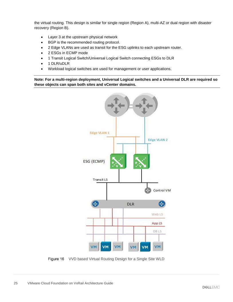
• Layer 3 at the upstream physical network
• BGP is the recommended routing protocol.
• 2 Edge VLANs are used as transit for the ESG uplinks to each upstream router.
• 2 ESGs in ECMP mode
• 1 Transit Logical Switch/Universal Logical Switch connecting ESGs to DLR
• 1 DLR/uDLR
• Workload logical switches are used for management or user applications.
Note: For a multi-region deployment, Universal Logical switches and a Universal DLR are required so
these objects can span both sites and vCenter domains.
VVD based Virtual Routing Design for a Single Site WLD

26 VMware Cloud Foundation on VxRail Architecture Guide
To expand on this design and consider both the management workload domain and one VI workload domain
for a single site deployment we would have the NSX virtual routing layout similar to that depicted in Figure 17.
This figure shows the eBGP peering between the management workload domain ESGs and the upstream
switches. These could be a TOR/Spine switch or potentially core switches, depending on the physical network
design. iBGP is used between the ESGs and the DLR. Basically BGP is used through the network design.
• BPG is used as the routing protocol for DLR/ESG/TOR/Spine and Core.
• 4 Uplink VLANs, each router will have a VLAN for both management and VI WLD ESGs.
• Management WLD transit logical switch to connect management WLD ESGs to management
WLD DLR
• VI WLD transit logical switch to connect VI WLD ESGs to VI WLD domain DLR
• Customer network design would define handoff to the core network.
NSX Virtual Routing – Single Site with Management and VI WLD
27 VMware Cloud Foundation on VxRail Architecture Guide
7 Physical network design considerations The VMware Cloud Foundation on VxRail Network design offers flexibility to allow for different topologies and
different network hardware vendors. This allows users to use their existing network infrastructure or
potentially add new hardware to an existing datacenter network infrastructure. Typically, datacenter network
design has been shifting away from classical 3-tier network topologies using primarily layer 2 fabric to the
newer Leaf and Spine layer 3 fabric architectures. When deciding whether to use layer 2 or layer 3, consider
the following factors:
• NSX ECMP Edge devices establish layer 3 routing adjacency with the first upstream layer 3
device to provide equal cost routing for management and workload traffic.
• The investment you have today in your current physical network infrastructure
• The advantages and disadvantages for both layer 2 and layer 3 designs. The following section
describes both designs and highlights the main advantages and disadvantages.
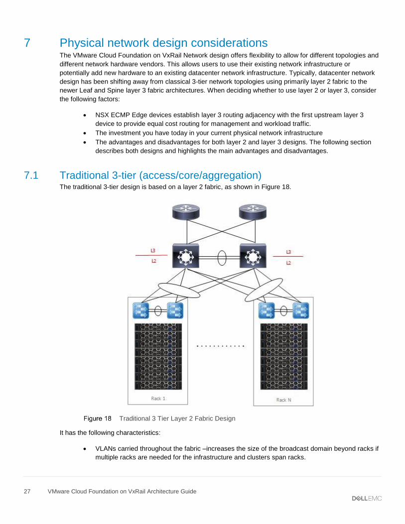
7.1 Traditional 3-tier (access/core/aggregation) The traditional 3-tier design is based on a layer 2 fabric, as shown in Figure 18.
Traditional 3 Tier Layer 2 Fabric Design
It has the following characteristics:
• VLANs carried throughout the fabric –increases the size of the broadcast domain beyond racks if
multiple racks are needed for the infrastructure and clusters span racks.
28 VMware Cloud Foundation on VxRail Architecture Guide
• The aggregation layer devices of each pod are the demarcation line between L2 and L3 network
domains.
• Default Gateway – HSRP/VRRP at the aggregation layer
• The NSX ESGs will peer with the routers at the aggregation layer.
Advantages:
• VLANs can span racks which can be useful for VxRail system VLANs like vSAN/vMotion and
node discovery.
• Layer 2 design might be considered less complex to implement.
Disadvantages:
• Large clusters spanning racks will create large broadcast domains.
• Interoperability issues between different switch vendors can introduce spanning tree issues in
large fabrics.
• The NSX ESGs for each workload domain will need to peer at the aggregation layer. For large
scale deployments with multiple workload domains, the configuration will become complex.
• The size of such a deployment is limited because the fabric elements have to share a limited
number of VLANs 4094. With NSX, the number of VLANs could be reduced so this might not be
an issue.
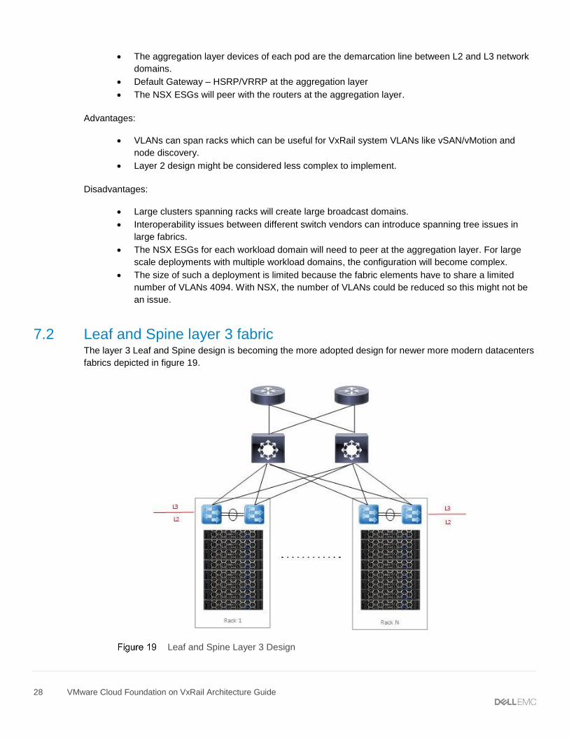
7.2 Leaf and Spine layer 3 fabric The layer 3 Leaf and Spine design is becoming the more adopted design for newer more modern datacenters
fabrics depicted in figure 19.
Leaf and Spine Layer 3 Design
29 VMware Cloud Foundation on VxRail Architecture Guide
It has the following characteristics:
• L3 is terminated at the leaf, thus all the VLANs originating from ESXi hosts terminate on leaf.
• The same VLANs can be reused for each rack.
• The leaf switches provide default gateway functionality.
• The NSX ESGs for each workload domain will peer with the leaf switches in each rack.
Advantages:
• Vendor agnostic - Multiple network hardware vendors can be used in the design.
• Reduced VLAN span across racks, thus smaller broadcast domains.
• East-West for an NSX domain can be confined within a rack with intra-rack routing at the leaf.
• East-West across NSX domains or Cross-Rack routed through the Spine.
• ESG peering is simplified by peering the workload domains with the leaf switches in the rack.
Disadvantages:
• The layer 2 VLANs cannot span racks. For clusters spanning racks, this will require a solution to
allow VxRail system traffic to span racks using hardware VTEPs.
• The layer 3 configuration might be more complex to implement.
7.3 Multi-rack design considerations It might be desirable to span workload domain clusters across racks to avoid a single point of failure within
one rack. The loudmouth protocol for VxRail node discovery requires VxRail nodes to reside on the same L2
private management discovery network. Additionally, VxRail does not yet support L3 for vSAN. L3 for vMotion
is a post VxRail cluster deployment operation and the management VMs will also need L2 adjacency so the
VMs can be migrated between racks. For a layer 3 Leaf/Spine fabric, this is a problem as the VLANs are
terminated at the leaf switches in each rack.
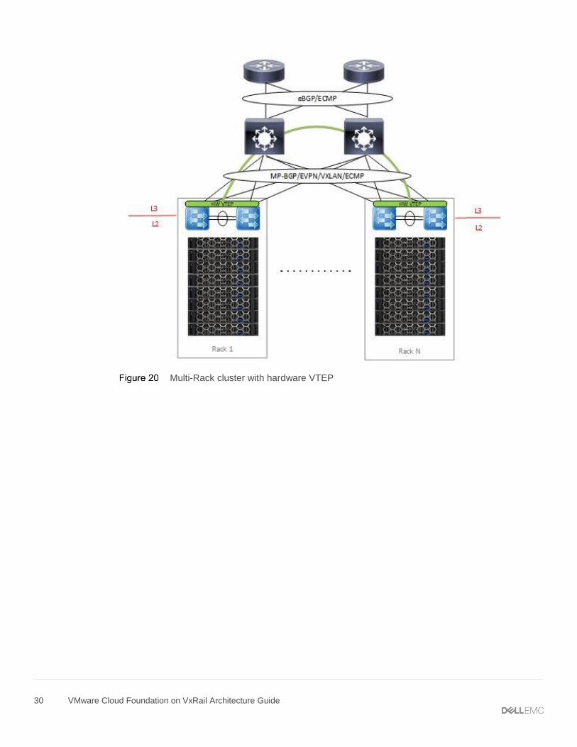
7.3.1 VxRail multi-rack cluster VxRail multi-rack cluster is a solution that allows a single (or multiple) VxRail cluster(s) to span between
racks. This particular solution uses a Dell networking switch hardware VTEP to provide an L2 overlay network
to extend L2 segments over an L3 underlay network for VxRail node discovery, vSAN, vMotion, management
and VM/App L2 network connectivity between racks. The following diagram is an example of a multi-rack
solution using hardware VTEP using VXLAN BGP EVPN. The advantage of VXLAN BGP EVPN over static
VXLAN configuration is that each VTEP is automatically learned as a member of a virtual network from the
EVPN routes received from the remote VTEP.
30 VMware Cloud Foundation on VxRail Architecture Guide
Multi-Rack cluster with hardware VTEP
31 VMware Cloud Foundation on VxRail Architecture Guide
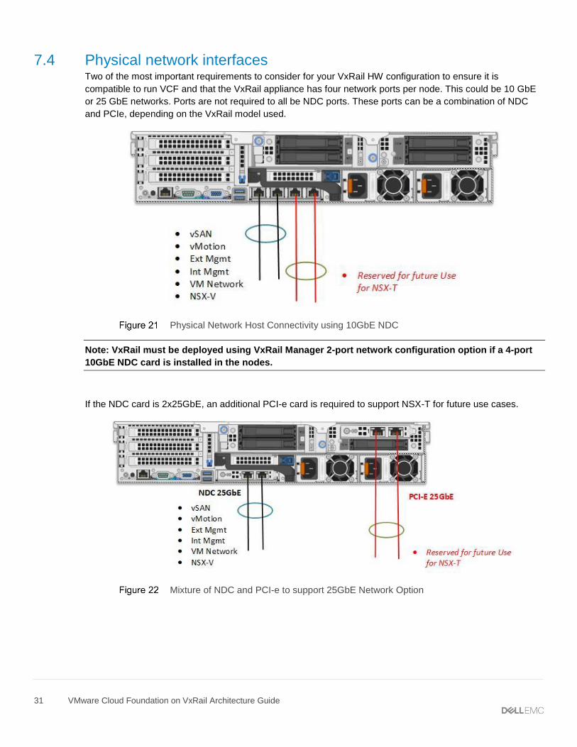
7.4 Physical network interfaces Two of the most important requirements to consider for your VxRail HW configuration to ensure it is
compatible to run VCF and that the VxRail appliance has four network ports per node. This could be 10 GbE
or 25 GbE networks. Ports are not required to all be NDC ports. These ports can be a combination of NDC
and PCIe, depending on the VxRail model used.
Physical Network Host Connectivity using 10GbE NDC
Note: VxRail must be deployed using VxRail Manager 2-port network configuration option if a 4-port
10GbE NDC card is installed in the nodes.
If the NDC card is 2x25GbE, an additional PCI-e card is required to support NSX-T for future use cases.
Mixture of NDC and PCI-e to support 25GbE Network Option
32 VMware Cloud Foundation on VxRail Architecture Guide
8 Multi-site design considerations The VMware Cloud Foundation on VxRail solution natively supports a stretched-cluster configuration between
two availability zones. The stretched-cluster configuration is partially automated by executing a pair of scripts
from the SDDC Manager. A disaster recovery solution is also supported but this is a manual configuration and
would require additional add-on products like SRM to be installed and configured following VVD reference
architecture.
8.1 Stretched cluster The management workload domain and VI workload domains can be stretched across two availability zones.
Availability zones can be located in either the same datacenter but in different racks/server rooms or in two
different datacenters in two different geographic locations. The same requirements for a native VxRail
stretched-cluster deployment are also required for a VMware Cloud Foundation on VxRail stretched-cluster
deployment, specifically those related to the network requirements.
Note: The VI workload domain cluster can only be stretched if the management workload domain
cluster is first stretched.
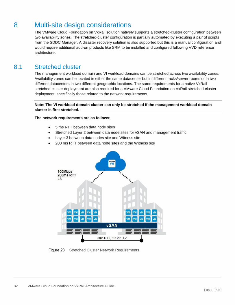
The network requirements are as follows:
• 5 ms RTT between data node sites
• Stretched Layer 2 between data node sites for vSAN and management traffic
• Layer 3 between data nodes site and Witness site
• 200 ms RTT between data node sites and the Witness site
Stretched Cluster Network Requirements
33 VMware Cloud Foundation on VxRail Architecture Guide
The following requirements are specific to VMware Cloud Foundation on VxRail and must also be considered.
• Management workload domain cluster requires minimum of four nodes per site (4+4).
• VI WLD requires a minimum of four nodes per site (4+4), secondary clusters require a minimum
of three nodes per site (3+3).
• All stretched-cluster configurations must be balanced with the same number of nodes on each
site.
Note: The Witness needs to be manually deployed at a third site and configured before VCF
configuration. For more information see the DELL EMC VxRAIL™ vSAN STRETCHED CLUSTERS
PLANNING GUIDE.
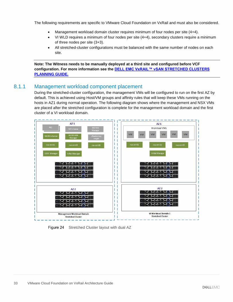
8.1.1 Management workload component placement During the stretched-cluster configuration, the management VMs will be configured to run on the first AZ by
default. This is achieved using Host/VM groups and affinity rules that will keep these VMs running on the
hosts in AZ1 during normal operation. The following diagram shows where the management and NSX VMs
are placed after the stretched configuration is complete for the management workload domain and the first
cluster of a VI workload domain.
Stretched Cluster layout with dual AZ
34 VMware Cloud Foundation on VxRail Architecture Guide
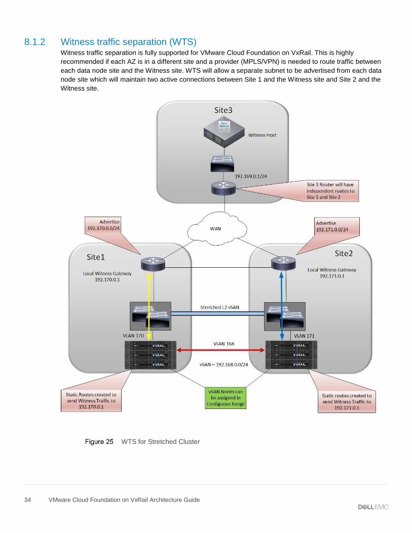
8.1.2 Witness traffic separation (WTS) Witness traffic separation is fully supported for VMware Cloud Foundation on VxRail. This is highly
recommended if each AZ is in a different site and a provider (MPLS/VPN) is needed to route traffic between
each data node site and the Witness site. WTS will allow a separate subnet to be advertised from each data
node site which will maintain two active connections between Site 1 and the Witness site and Site 2 and the
Witness site.
WTS for Stretched Cluster
35 VMware Cloud Foundation on VxRail Architecture Guide
8.1.3 NSX stretched-cluster routing design The NSX stretched cluster design will closely align with the VVD reference architecture. Currently this
requires a manual Day 2 deployment using VVD documentation as a guide for the NSX routing design. For
stretched-cluster deployments, there is no requirement for cross vCenter NSX or universal objects. Standard
logical switches and DLRs can be used in the design. Following is an example of such a design. The physical
network design will vary depending on your existing network infrastructure.
Key points to consider for stretched-cluster routing design:
• Single management and VI WLD vCenter/NSX Manager
• L2 Stretch for Mgmt/vSAN/vMotion
• BPG used as the routing protocol for DLR/ESG/TOR/Spine.
• For each Site 4 Uplink VLANs, each router will have a VLAN for both management and VI WLD.
• Site 1 ESGs pinned to Site 1 hosts
• Site 2 ESGs pinned to Site 2 Hosts
• Mgmt WLD transit logical switch to connect Mgmt WLD ESGs to Mgmt WLD DLR
• VI WLD transit logical switch to connect VI WLD ESGs to VI WLD DLR
• Physical network design will vary depending on existing network infrastructure.
36 VMware Cloud Foundation on VxRail Architecture Guide
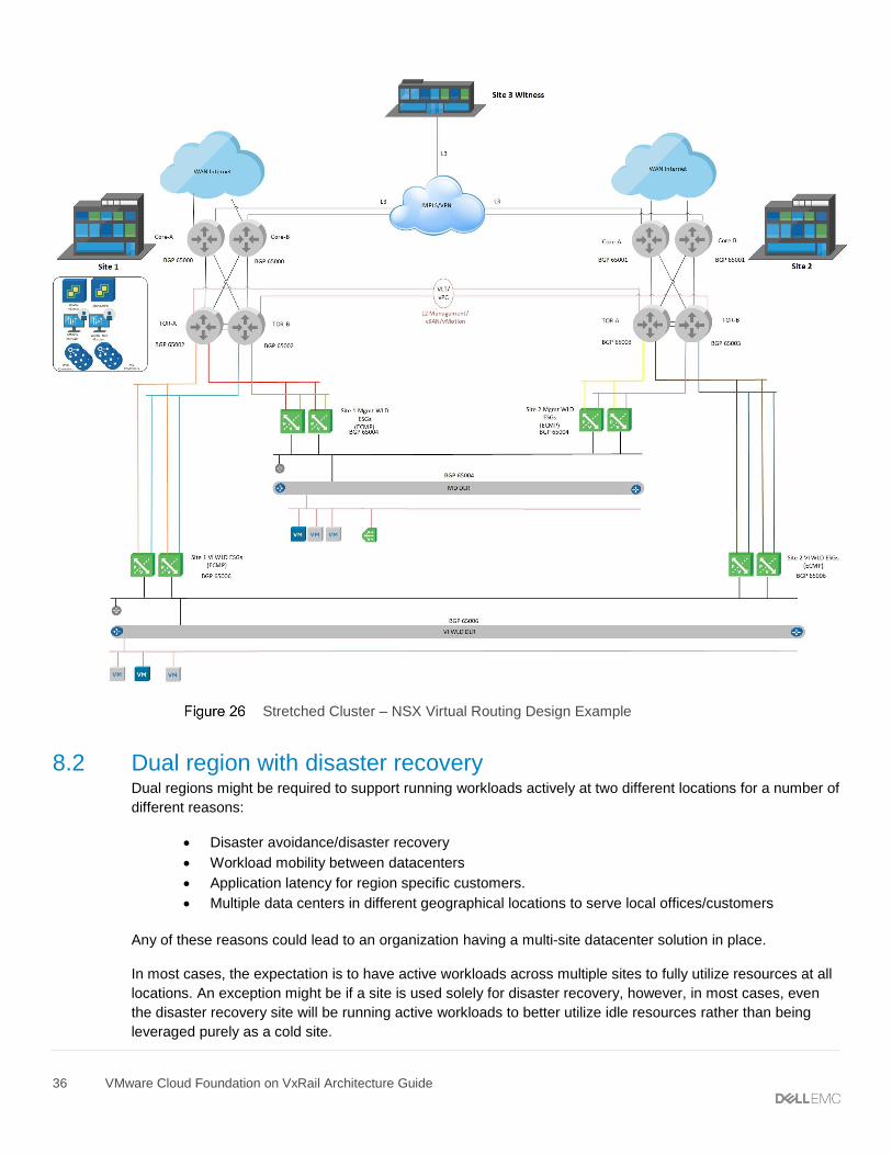
Stretched Cluster – NSX Virtual Routing Design Example
8.2 Dual region with disaster recovery Dual regions might be required to support running workloads actively at two different locations for a number of
different reasons:
• Disaster avoidance/disaster recovery
• Workload mobility between datacenters
• Application latency for region specific customers.
• Multiple data centers in different geographical locations to serve local offices/customers
Any of these reasons could lead to an organization having a multi-site datacenter solution in place.
In most cases, the expectation is to have active workloads across multiple sites to fully utilize resources at all
locations. An exception might be if a site is used solely for disaster recovery, however, in most cases, even
the disaster recovery site will be running active workloads to better utilize idle resources rather than being
leveraged purely as a cold site.
37 VMware Cloud Foundation on VxRail Architecture Guide
The current VMware Cloud Foundation release does not support the automated deployment of dual region
SDDC, but it can be manually deployed and configured using VVD reference architecture and documentation.
The VMware Cloud Foundation Site Protection and Disaster Recovery Guide can be found on VMware’s VCF
documentation page.
The procedures documented include the installation of VMware Site Recovery Manager with vSphere
Replication to be used as the mechanism to protect management domain workloads by replicating the data
across site and orchestrate disaster recovery. It also details the NSX configuration needed to support a multi-
site network design, the steps follow VVD reference architecture.
Note: This documentation only covers protecting the management workloads that run on the
management workload domain and does not include tenant workloads running on the VI workload
domains.
Note: For the deployment of additional NSX and vSphere Replication VMs, additional capacity will be
required. Refer to the VVD Planning and Preparation Guide for details.
Cross vCenter NSX is used to provide workload mobility for the solution. It allows spanning of logical
networks and security policies across multiple vCenter domains while maintaining the use of dedicated
vCenter servers per site. In this solution, vSphere clusters are not stretched across sites. Instead, the NSX
logical networking and security domains span vCenter domains. A stretched-storage solution is not required
or used between the vCenter domains at each site. Local storage and the latency requirements between sites
is a maximum RTT of 150 ms.
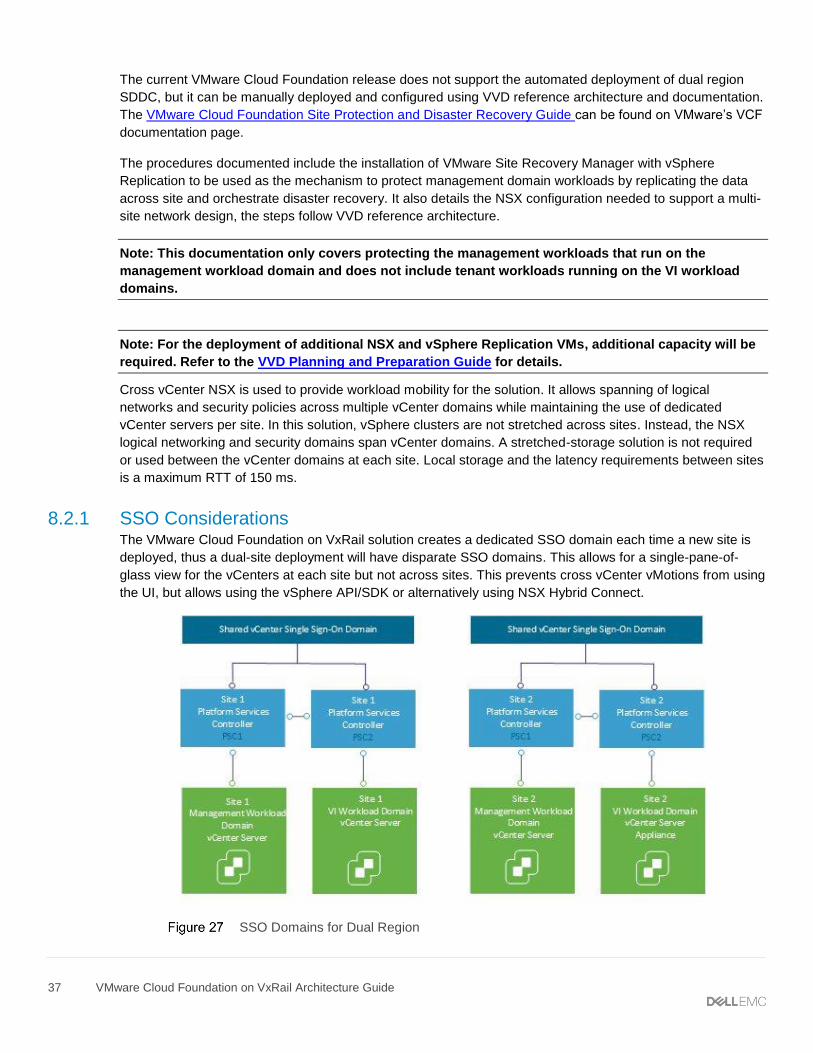
8.2.1 SSO Considerations The VMware Cloud Foundation on VxRail solution creates a dedicated SSO domain each time a new site is
deployed, thus a dual-site deployment will have disparate SSO domains. This allows for a single-pane-of-
glass view for the vCenters at each site but not across sites. This prevents cross vCenter vMotions from using
the UI, but allows using the vSphere API/SDK or alternatively using NSX Hybrid Connect.
SSO Domains for Dual Region
38 VMware Cloud Foundation on VxRail Architecture Guide
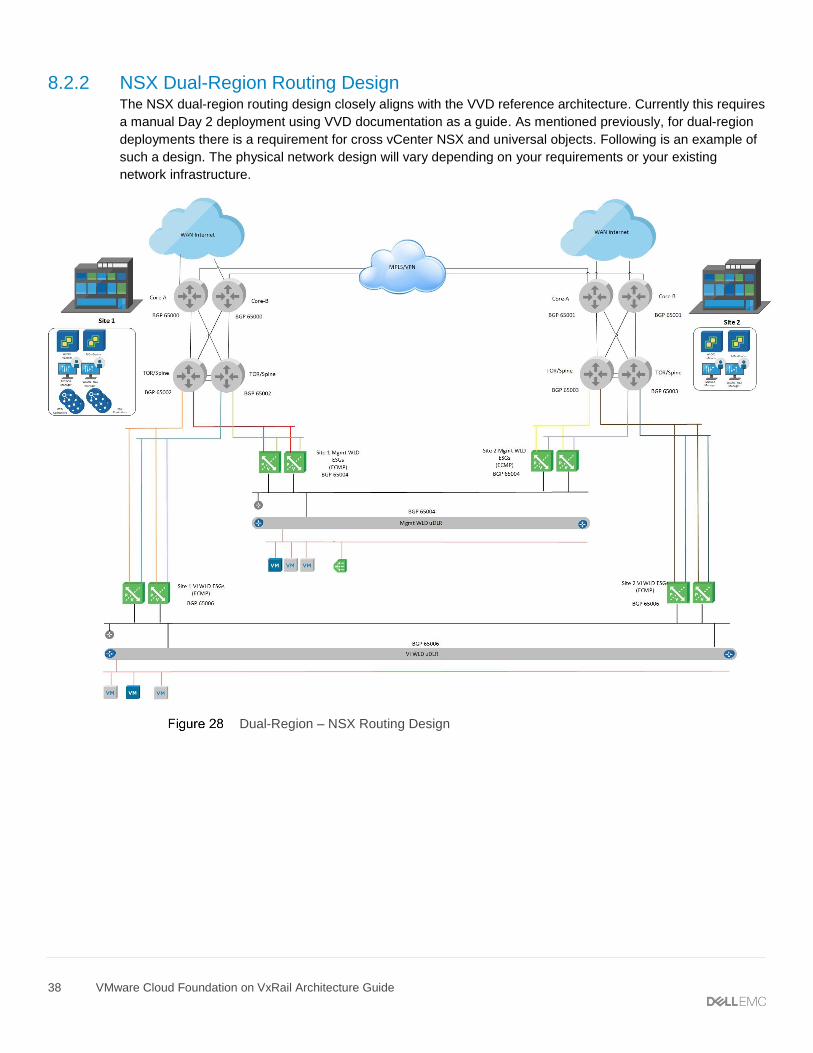
8.2.2 NSX Dual-Region Routing Design The NSX dual-region routing design closely aligns with the VVD reference architecture. Currently this requires
a manual Day 2 deployment using VVD documentation as a guide. As mentioned previously, for dual-region
deployments there is a requirement for cross vCenter NSX and universal objects. Following is an example of
such a design. The physical network design will vary depending on your requirements or your existing
network infrastructure.
Dual-Region – NSX Routing Design
39 VMware Cloud Foundation on VxRail Architecture Guide
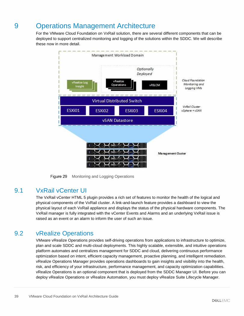
9 Operations Management Architecture For the VMware Cloud Foundation on VxRail solution, there are several different components that can be
deployed to support centralized monitoring and logging of the solutions within the SDDC. We will describe
these now in more detail.
Monitoring and Logging Operations
9.1 VxRail vCenter UI The VxRail vCenter HTML 5 plugin provides a rich set of features to monitor the health of the logical and
physical components of the VxRail cluster. A link-and-launch feature provides a dashboard to view the
physical layout of each VxRail appliance and displays the status of the physical hardware components. The
VxRail manager is fully integrated with the vCenter Events and Alarms and an underlying VxRail issue is
raised as an event or an alarm to inform the user of such an issue.
9.2 vRealize Operations VMware vRealize Operations provides self-driving operations from applications to infrastructure to optimize,
plan and scale SDDC and multi-cloud deployments. This highly scalable, extensible, and intuitive operations
platform automates and centralizes management for SDDC and cloud, delivering continuous performance
optimization based on intent, efficient capacity management, proactive planning, and intelligent remediation.
vRealize Operations Manager provides operations dashboards to gain insights and visibility into the health,
risk, and efficiency of your infrastructure, performance management, and capacity optimization capabilities.
vRealize Operations is an optional component that is deployed from the SDDC Manager UI. Before you can
deploy vRealize Operations or vRealize Automation, you must deploy vRealize Suite Lifecycle Manager.
40 VMware Cloud Foundation on VxRail Architecture Guide
9.3 vRealize Log Insight VMware vRealize Log Insight delivers automated log management through log aggregation, analytics, and
search capabilities. With an integrated cloud operations management approach. It provides the operational
intelligence and enterprise-wide visibility that is required to enable service levels proactively and operational
efficiency in dynamic hybrid cloud environments. vRealize Log Insight is deployed in the management
workload domain during the VCF bring-up process. It consists of three VMs deployed in a cluster and the
internal Load Balancer feature is enabled.
41 VMware Cloud Foundation on VxRail Architecture Guide
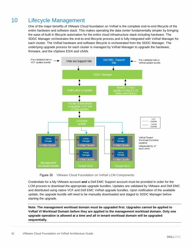
10 Lifecycle Management One of the major benefits of VMware Cloud foundation on VxRail is the complete end-to-end lifecycle of the
entire hardware and software stack. This makes operating the data center fundamentally simpler by bringing
the ease-of-built in lifecycle automation for the entire cloud infrastructure stack including hardware. The
SDDC Manager orchestrates the end-to-end lifecycle process and is fully integrated with VxRail Manager for
each cluster. The VxRail hardware and software lifecycle is orchestrated from the SDDC Manager. The
underlying upgrade process for each cluster is managed by VxRail Manager to upgrade the hardware,
firmware, and the vSphere ESXi and vSAN.
VMware Cloud Foundation on VxRail LCM Components
Credentials for a My VMware account and a Dell EMC Support account must be provided in order for the
LCM process to download the appropriate upgrade bundles. Updates are validated by VMware and Dell EMC
and distributed using native VCF and Dell EMC VxRail upgrade bundles. Upon notification of the available
update, the upgrade bundle will need to be manually downloaded and staged to SDDC Manager before
starting the upgrade.
Note: The management workload domain must be upgraded first. Upgrades cannot be applied to
VxRail VI Workload Domain before they are applied to the management workload domain. Only one
upgrade operation is allowed at a time and all in tenant workload domain will be upgraded
sequentially.
42 VMware Cloud Foundation on VxRail Architecture Guide
10.1 vRealize Suite Lifecycle Manager The VMware vRealize Suite Lifecycle Manager automates the lifecycle management of the vRealize Suite. It
must be deployed before any vRealize Operations or vRealize Automation components can be deployed. The
vRealize Suite Lifecycle Manager contains the functional elements that collaborate to orchestrate the lifecycle
management operations of the vRealize Suite environment.
43 VMware Cloud Foundation on VxRail Architecture Guide
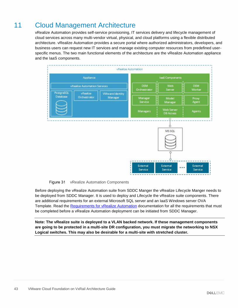
11 Cloud Management Architecture vRealize Automation provides self-service provisioning, IT services delivery and lifecycle management of
cloud services across many multi-vendor virtual, physical, and cloud platforms using a flexible distributed
architecture. vRealize Automation provides a secure portal where authorized administrators, developers, and
business users can request new IT services and manage existing computer resources from predefined user-
specific menus. The two main functional elements of the architecture are the vRealize Automation appliance
and the IaaS components.
vRealize Automation Components
Before deploying the vRealize Automation suite from SDDC Manger the vRealize Lifecycle Manger needs to
be deployed from SDDC Manager. It is used to deploy and Lifecycle the vRealize suite components. There
are additional requirements for an external Microsoft SQL server and an IaaS Windows server OVA
Template. Read the Requirements for vRealize Automation documentation for all the requirements that must
be completed before a vRealize Automation deployment can be initiated from SDDC Manager.
Note: The vRealize suite is deployed to a VLAN backed network. If these management components
are going to be protected in a multi-site DR configuration, you must migrate the networking to NSX
Logical switches. This may also be desirable for a multi-site with stretched cluster.