Embed Size (px)
Citation preview

Pattern Recognition Letters 34 (2013) 42–51
Contents lists available at SciVerse ScienceDirect
Pattern Recognition Letters
journal homepage: www.elsevier .com/locate /patrec
Visible and infrared image registration in man-made environmentsemploying hybrid visual features q
Jungong Han ⇑, Eric J. Pauwels, Paul de ZeeuwCentrum Wiskunde & Informatica (CWI), Science Park 123, Amsterdam, The Netherlands
a r t i c l e i n f o a b s t r a c t
Article history:Available online 4 April 2012
Keywords:Image registrationLine detectionGeometric analysisLocal deformation
0167-8655/$ - see front matter � 2012 Elsevier B.V. Ahttp://dx.doi.org/10.1016/j.patrec.2012.03.022
q This work is supported by EU-FP7 FIRESENSE pro⇑ Corresponding author. Tel.: +31 205924209.
E-mail address: [email protected] (J. Han).
We present a new method to register a pair of images captured in different image modalities. Unlike mostof existing systems that register images by aligning single type of visual features, e.g., interest point orcontour, we try to align hybrid visual features, including straight lines and interest points. The entirealgorithm is carried out in two stages: line-based global transform approximation and point-based localtransform adaptation. In the first stage, straight lines derived from edge pixels are employed to find cor-respondences between two images in order to estimate a global perspective transformation. In the sec-ond stage, we divide the entire image into non-overlapping cells with fixed size. The point having thestrongest corner response within each cell is selected as the interest point. These points are transformedto other image based on the global transform, and then used to bootstrap a local correspondence search.Experimental evidence shows this method achieves better accuracy for registering visible and long wave-length infrared images/videos as compared to state-of-the-art approaches.
� 2012 Elsevier B.V. All rights reserved.
1. Introduction
Recent advances in imaging, networking, data processing andstorage technology have resulted in an explosion in the use of mul-timodality images in a variety of fields, including video surveil-lance, urban monitoring, cultural heritage area protection andmany others. The integration of images from multiple channelscan provide complementary information and therefore increasethe accuracy of the overall decision making process. A fundamentalproblem in multimodality image integration is that of aligningimages of the same scene observed from different positions and/or in different sensor modalities. This problem is known as imageregistration and the objective is to recover the correspondences be-tween the images. Once such correspondences have been found, allimages can be transformed into the same reference, enabling onaugmenting of the information in one image with the informationfrom the others.
1.1. Prior work on image registration
Several related survey papers for image registration have ap-peared over the years. Brown (1992), Zitova and Flusser (2003)and Xiong and Zhang (2010) have provided a broad overview ofover two hundred papers for registering different types of sensors.
ll rights reserved.
ject.
Before embarking on a more in-depth discussion of some of the re-lated prior work, we point out that in accordance with most of theliterature, we also divide existing techniques into two categories:pixel-based methods and feature-based methods. Pixel-basedmethods first define a metric, such as the sum of squared differ-ences or mutual information (Zitova and Flusser, 2003), whichmeasures the distance of two pixels from different images. The reg-istration problem is then recast as the total distance minimizationbetween all pixels in one image and the corresponding pixels in theother image. In feature-based methods, interest points like Harriscorners, scale invariant feature transform (SIFT), speed-up robustfeature (SURF), etc., are first extracted from images. Subsequently,these features are matched based on metrics, such as crosscorrelation or mutual information. Once more than four featurecorrespondences are obtained, the projective transform can becomputed. In principle, a pixel-based method is better than afeature-based method, because the former takes all pixels into ac-count when minimizing the cost function, while the latter mini-mizes the cost function based on a part of pixels only. In practicehowever, feature-based method performs well in many applica-tions, because interest points are supposed to be distinctive, thusleading to better matching. Moreover, pixel-based methods aremuch more expensive than feature-based algorithms in the sensethat every pixel needs to be involved in the computation. Consid-ering both accuracy and efficiency of the algorithm, we adopt thefeature-based method in this paper. Therefore, we limit our reviewto feature-based registration methods, and pay special attention tovisible (ViS) and infrared (IR) image registration.
J. Han et al. / Pattern Recognition Letters 34 (2013) 42–51 43
Many approaches have been proposed for automatically regis-tering IR and ViS images. In (Hrkac et al., 2007), an approach devel-oped for aligning IR and ViS images is presented, in which thecorner points are used. The similarity between the ViS cornersand corners from IR image is measured by directed partial Haus-dorff distance. Firmenich et al. (2011) employ the multispectral cor-ner detector which aims to improve the quality of interest pointextraction. The new method generalizes the Harris detector bysumming autocorrelation matrices per band. In (Jarc et al., 2007),the image is first processed by using laws texture coefficient,which combines four one-dimensional filters. Each filtered imageis then converted to a sort of texture-like energy image. The imagealignment is conducted based on measuring/optimizing mutualinformation of two quantized texture energy images. Edge/gradi-ent information is a popular feature as their magnitudes (Leeet al., 2010) and orientations (Firmenich et al., 2011; Kim et al.,2008) may match between infrared and visible images. In (Coiraset al., 2000), authors first extract edge segments, which are thengrouped to form triangles. The transform can be computed bymatching triangles from source to destination images. Huang andChen (2002) proposes a contour-based registration algorithm,which integrates the invariant moments with the orientation func-tion of the contours to establish the correspondences of the con-tours in the two images. Normally it is difficult to obtainaccurate registration by using contour-based method, because pre-cisely matching all contours detected from two images is challeng-ing. Moreover, this method drastically increases computation timecompared to interest point-based registration. To improve thiswork, Han and Bhanu (2007) propose to find correspondences onmoving contours. They extract silhouettes of moving humans fromboth images. Matching only the contours of human bodies signifi-cantly improves both the performance and the efficiency of thealgorithm. An alternative (Caspi et al., 2006) is to make use ofthe object motion paths generated by object tracking algorithm.Finding correspondences between trajectories helps to alignimages. This type of algorithm works very well when moving ob-jects can be precisely tracked from both channels. Unfortunately,the current tracking algorithm is not satisfactory in manyapplications.
1.2. Problem statement
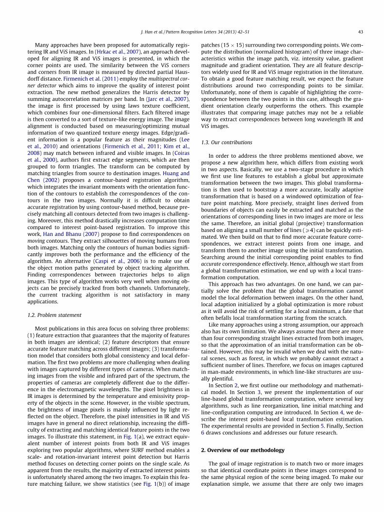
Most publications in this area focus on solving three problems:(1) feature extraction that guarantees that the majority of featuresin both images are identical; (2) feature descriptors that ensureaccurate feature matching across different images; (3) transforma-tion model that considers both global consistency and local defor-mation. The first two problems are more challenging when dealingwith images captured by different types of cameras. When match-ing images from the visible and infrared part of the spectrum, theproperties of cameras are completely different due to the differ-ence in the electromagnetic wavelengths. The pixel brightness inIR images is determined by the temperature and emissivity prop-erty of the objects in the scene. However, in the visible spectrum,the brightness of image pixels is mainly influenced by light re-flected on the object. Therefore, the pixel intensities in IR and ViSimages have in general no direct relationship, increasing the diffi-culty of extracting and matching identical feature points in the twoimages. To illustrate this statement, in Fig. 1(a), we extract equiv-alent number of interest points from both IR and ViS imagesexploring two popular algorithms, where SURF method enables ascale- and rotation-invariant interest point detection but Harrismethod focuses on detecting corner points on the single scale. Asapparent from the results, the majority of extracted interest pointsis unfortunately shared among the two images. To explain this fea-ture matching failure, we show statistics (see Fig. 1(b)) of image
patches (15 � 15) surrounding two corresponding points. We com-pute the distribution (normalized histogram) of three image char-acteristics within the image patch, viz. intensity value, gradientmagnitude and gradient orientation. They are all feature descrip-tors widely used for IR and ViS image registration in the literature.To obtain a good feature matching result, we expect the featuredistributions around two corresponding points to be similar.Unfortunately, none of them is capable of highlighting the corre-spondence between the two points in this case, although the gra-dient orientation clearly outperforms the others. This exampleillustrates that comparing image patches may not be a reliableway to extract correspondences between long wavelength IR andViS images.
1.3. Our contributions
In order to address the three problems mentioned above, wepropose a new algorithm here, which differs from existing workin two aspects. Basically, we use a two-stage procedure in whichwe first use line features to establish a global but approximatetransformation between the two images. This global transforma-tion is then used to bootstrap a more accurate, locally adaptivetransformation that is based on a windowed optimization of fea-ture point matching. More precisely, straight lines derived fromboundaries of objects can easily be extracted and matched as theorientations of corresponding lines in two images are more or lessthe same. Therefore, an initial global (projective) transformationbased on aligning a small number of lines (P4) can be quickly esti-mated. We then build on that to find more accurate feature corre-spondences, we extract interest points from one image, andtransform them to another image using the initial transformation.Searching around the initial corresponding point enables to findaccurate correspondence effectively. Hence, although we start froma global transformation estimation, we end up with a local trans-formation computation.
This approach has two advantages. On one hand, we can par-tially solve the problem that the global transformation cannotmodel the local deformation between images. On the other hand,local adaption initialized by a global optimization is more robustas it will avoid the risk of settling for a local minimum, a fate thatoften befalls local transformation starting from the scratch.
Like many approaches using a strong assumption, our approachalso has its own limitation. We always assume that there are morethan four corresponding straight lines extracted from both images,so that the approximation of an initial transformation can be ob-tained. However, this may be invalid when we deal with the natu-ral scenes, such as forest, in which we probably cannot extract asufficient number of lines. Therefore, we focus on images capturedin man-made environments, in which line-like structures are usu-ally plentiful.
In Section 2, we first outline our methodology and mathemati-cal model. In Section 3, we present the implementation of ourline-based global transformation computation, where several keyalgorithms, such as line reorganization, line initial matching andline-configuration computing are introduced. In Section 4, we de-scribe the interest point-based local transformation estimation.The experimental results are provided in Section 5. Finally, Section6 draws conclusions and addresses our future research.
2. Overview of our methodology
The goal of image registration is to match two or more imagesso that identical coordinate points in these images correspond tothe same physical region of the scene being imaged. To make ourexplanation simple, we assume that there are only two images
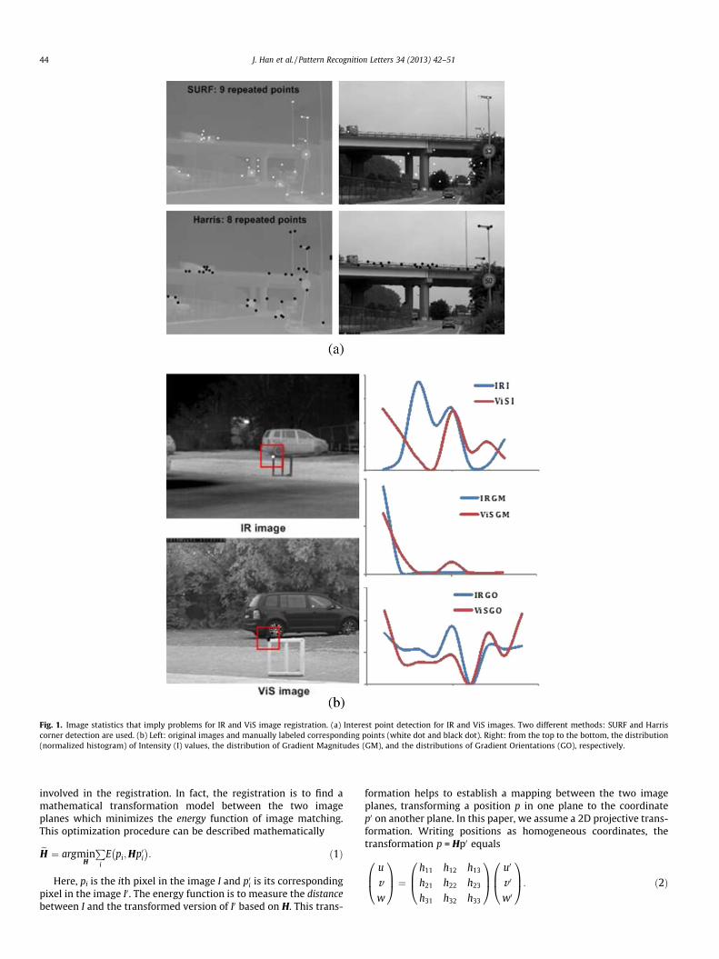
Fig. 1. Image statistics that imply problems for IR and ViS image registration. (a) Interest point detection for IR and ViS images. Two different methods: SURF and Harriscorner detection are used. (b) Left: original images and manually labeled corresponding points (white dot and black dot). Right: from the top to the bottom, the distribution(normalized histogram) of Intensity (I) values, the distribution of Gradient Magnitudes (GM), and the distributions of Gradient Orientations (GO), respectively.
44 J. Han et al. / Pattern Recognition Letters 34 (2013) 42–51
involved in the registration. In fact, the registration is to find amathematical transformation model between the two imageplanes which minimizes the energy function of image matching.This optimization procedure can be described mathematically
eH ¼ argminH
Pi
E pi;Hp0i� �
: ð1Þ
Here, pi is the ith pixel in the image I and p0i is its correspondingpixel in the image I0. The energy function is to measure the distancebetween I and the transformed version of I0 based on H. This trans-
formation helps to establish a mapping between the two imageplanes, transforming a position p in one plane to the coordinatep0 on another plane. In this paper, we assume a 2D projective trans-formation. Writing positions as homogeneous coordinates, thetransformation p = Hp0 equals
u
vw
0B@1CA ¼ h11 h12 h13
h21 h22 h23
h31 h32 h33
0B@1CA u0
v 0
w0
0B@1CA: ð2Þ

J. Han et al. / Pattern Recognition Letters 34 (2013) 42–51 45
Homogeneous coordinates are scaling invariant, reducing thedegrees of freedom for the matrix H to eight. In order to determinethe eight parameters, at least four point-correspondences betweenthe two images have to be found. In the literature, most publica-tions rely on interest (corner) points for establishing point-correspondences.
If all detected interest points are involved in the computation of(1), there will be only one transformation between images, whichis called global transformation. Alternatively, the image can alsotreated as a composition of patches, where each patch is matchedto the corresponding patch in another image. The transformation Hbetween two corresponding patches can also be estimated using(1), for which the involved interest points are restricted to lie with-in the patch. Hence, the overall transformation between the imagesis composed of many local transformations, each with differentparameters. The global transformation has the advantage of havinga relatively small number of parameters to be estimated, and theglobal nature of the model ensures a consistent transformationacross the entire image, while the disadvantage is that one globalmapping cannot properly handle images deformed locally. On thecontrary, the local transformation is able to handle local deforma-tion. However, its computational load is heavy due to the largernumber of parameters that need to be estimated. Additionally, itis not easy to guarantee global consistency.
To own the benefits from both transformations, we try to com-bine them in our framework. The algorithm is carried out in twostages, as depicted in Fig. 2. In the first stage, we estimate a globalperspective transformation by aligning straight lines derived fromedges of the images. These lines strongly relate to boundaries ofobjects, which often appear in both images though IR sensor andViS sensor have significantly different properties. We have chosena perspective (projective) model for the transformation betweenthe two images as this is the appropriate exact transformationwhenever the cameras are observing a planar scene from differentviewpoints and viewing angles. It is also an excellent approxima-tion whenever the cameras are observing a 3D scene in whichthe depth difference between the objects is small compared tothe distance to the cameras. Fortunately, this assumption usuallyholds in our application. In the second stage, we divide the entireimage into cells of fixed size. The most salient interest point is ex-tracted from each cell, and is transformed to another image basedon the global transformation matrix. We allow the interest point tofind a better correspondence within a window surrounding its ini-tial corresponding point. By doing so, we can cope with the localgeometric differences between images. Since the size of the search-ing window is limited, the estimated local transformation will notbe significantly different from the global one, thus guaranteeing aglobal consistency.
3. The implementation of line-based global transformation
3.1. The mathematical model
As we mentioned before, the first stage of our work aims to ob-tain a global projective (perspective) transformation by aligningstraight lines between two images. Theoretically, the objective isto compute a point-to-point transform matrix H explained by (2).
Fig. 2. Framework of our system, which composes of line-based global transform
However, due to the well-known principle of duality in projectivegeometry, it follows that the transformation can also be deter-mined by specifying a sufficient number of line correspondences.
Let us now denote two corresponding lines (l and l0) on both im-age coordinates as:
auþ bv þw ¼ 0 and a0u0 þ b0v 0 þw0 ¼ 0: ð3Þ
The above two lines can be expressed by their homogenous coordi-nates which are recorded by a linear transform A : (a,b,1)T and A0 :(a0,b0,1)T, respectively. Based on (2), we can describe the relation be-tween these two lines by a transformation bH , which is specified by:
A ¼ bHA0: ð4Þ
To clarify the relationship between bH and H in (2), we rewrite theline equation to
AT
u
vw
0B@1CA ¼ 0 and ðA0ÞT
u0
v 0
w0
0B@1CA ¼ 0: ð5Þ
If we substitute (4) into (5), it will become
uvw
0B@1CA ¼ bH�T
u0
v 0
w0
0B@1CA: ð6Þ
Comparing (6) and (2), we can deduce that H ¼ bH�T . Obviously, it ispossible to compute a point-to-point transformation H given aline-to-line mapping bH . Eq. (6) also confirms that four line-correspondences suffice to compute bH (as expected from duality).
3.2. Algorithm implementation
Our line-based perspective transformation estimation consistsof two modules, addressing line generation and line matching,respectively. The line generation module consists of line detection,line labeling and sorting. The line matching module includes initialmatching and geometric matching of line composition. All stepsare designed with an eye on efficiency.
3.2.1. Line generationThe input of our line detection algorithm is the edge pixel ex-
tracted by the Canny operator. Prior to the edge extraction step,we have a contrast enhancement step based on the histogramequalization, which helps to detect the blurred edge pixels. We uti-lize a RANSAC-like algorithm (Han et al., 2008, 2011) discussed inour previous work to detect the dominant line given the data-set.RANSAC is a randomized algorithm that hypothesizes a set of mod-el parameters and evaluates the quality of the parameters. Afterseveral hypotheses have been evaluated, the best one is chosen.Specifically, we hypothesize a line by randomly selecting two edgepixels, from which we compute line parameter g. For this linehypothesis, we compute a score s(g) as
sðgÞ ¼Pðx;yÞ2X
maxðs� dðg; x; yÞ;0Þ; ð7Þ
where X is the set of edge pixels and d(g,x,y) denotes the distancebetween (x,y) and the line g. This score effectively computes the
ation estimation and interest point-based local transformation computation.

46 J. Han et al. / Pattern Recognition Letters 34 (2013) 42–51
support of a line hypothesis as the number of edge pixels close (asdetermined by s) to the line, weighted with their distance to theline. The score and the line parameters are stored and the processis repeated until about 25 hypotheses are generated randomly. Atthe end, the hypothesis with the highest score is selected. Theoutput of this detection algorithm also includes the start- andend-point of each line. More precisely, it returns a line segment.We filter out some shorter line segments, and extend the linesegments to the image borders. The reason for the step is that linesegments extracted from both images vary dramatically, but mostmajor segments with sufficient length are appeared in both images.
Next, lines are labeled as either ‘‘lying’’ or ‘‘standing’’. This labelis determined by the parameter:
Lls ¼ jxend � xstartj=Dstart!end; ð8Þ
where xstart and xend refer to x coordinates of start point and endpoint of a line, respectively. Dstart ? end denotes the distance be-tween these two points. If Lls is larger than 0.7, the line is labeledas a lying line. Otherwise, the line is considered to be a standingline. Note that the value of this threshold is not that important inthe sense that it may only influence the initial matching of one ortwo line, whose Lls is very close to the threshold. For this extremecase, one line might be labeled as a ‘‘lying’’ line in one image butis labeled as a ‘‘standing’’ line in another image, resulting in a wronginitial line matching. However, this mistake of the individual linematching is not critical, because our algorithm is attempting to findthe best line-configuration matching between images, which is asort of optimization procedure based on many lines. After labelinglines, the set of standing lines are ordered left to right, the set of ly-ing lines from top to bottom. Later, when we will search for corre-spondences between images, we will put the constraint on theassignment that the order must be preserved. This constraint islikely valid in case that our transform is either affine transform orperspective transform.
Finally, the line is modeled by three parameters, which are Lls, spand os. If the line is a lying line, sp is defined as the angle of the lineto the x-axis, and os means the offset of the line on the y-axis. Theroles of the x- and y-axis are reversed in case of a ‘‘standing’’ line.The definitions for sp and os are just inverse if line is a standingline. Fig. 3 shows the samples processed by our line generationalgorithm.
3.2.2. Line matchingAs we can see from the problem statement part, feature initial
matching schemes used by existing systems are in general notaccurate enough. The main reason is that two images capturedby different modalities are quite different at the pixel level. Tosolve this problem, our system enables a sort of one-to-many fea-ture matching, which allows a line in one image to have several
Fig. 3. Line generation results for two samples. Lying lines and standing lines are markedinterpretation of the references to colour in this figure legend, the reader is referred to
correspondences on another image. By doing so, we can increasethe likelihood that several matching candidates must include thecorrect one. The basic idea for this initial matching is to checkand compare three parameters of two lines located in two images.The first parameter is Lls, where we assume that two correspondinglines should have similar Lls. The assumption is valid for mostapplications, where modalities are mounted on the same platform.The second parameter is sp, where we assume that correspondinglines have similar slope to the axis. The last parameter is to com-pare distributions of the edge pixel surrounding the line. The sur-rounding area is the zone between two border lines, which havethe same slope with the candidate line but with ±� offset shift,respectively. The distribution of the edge pixel within this areacan be simply specified by the edge pixel percentage pecedge of thatarea, equaling to Nedge/Ntotal. Here, Nedge refers to the number ofedge pixels within that area, while Ntotal means the total numberof pixels within that area. If we denote the parameters of two can-didate lines as (Lls,sp,pecedge) and ðeLls;fsp;gpecedgeÞ, our matchingscore S can thus be formulated as:
S ¼ KLls � eLls
rLls
!� K sp�fsp
rsp
� �� K
pecedge �gpecedge
rpec
!: ð9Þ
The three terms in the equation implement the same logic: K(�) isthe Epanechnikov kernel function and r indicates the width ofthe kernel, which can be set manually. We compute the matchingscores between a given line and all candidate lines. Instead ofselecting the best one, we allow one line to have three candidatecorrespondences in terms of the ranking of the matching score.
After this initial line matching stage, we proceed by process-ing the alignment of geometric configurations comprising fourlines. Earlier we pointed out that the matching result betweentwo individual lines may not be reliable. However, the geometricconfiguration (layout) of different lines is much more consistentbetween images. This observation motivated us to align imagesby minimizing the discrepancy between two geometric configu-rations formed by lines. The basic idea is that we randomlychoose four lines from the first image, thus creating a so-calledmini-configuration. Depending on the initial matching result, wewill have several corresponding mini-configurations in the sec-ond image. Each configuration-correspondence allows us to com-pute the parameters of a projective transformation by solvingthe system of linear Eq. (4). Using the transformation thus ob-tained, we project one image onto the other image. The matchbetween two images is evaluated by computing the total dis-tance between each line and its closest projected line. We itera-tively search all possible configuration-correspondences andsettle for the one that minimizes the total distance as the bestconfiguration-correspondence. The transformation can thus be
with different colors. The original edge pixels are labeled with the white color.(Forthe web version of this article).
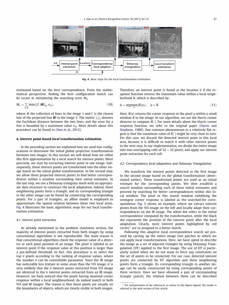
Fig. 4. Basic steps for the local transformation estimation.
1 For interpretation of the references to colour in this figure legend, the reader isreferred to the web version of this article.
J. Han et al. / Pattern Recognition Letters 34 (2013) 42–51 47
estimated based on the best correspondence. From the mathe-matical perspective, finding the best configuration match canbe recast as minimizing the matching error Me,
Me ¼Pl2U
minðkl0;Hlk2; emÞ; ð10Þ
where U the collection of lines in the image 1 and l0 is the closestline of the projected line Hl in the image 2. The metric k,k2 denotesthe Euclidean distance between the two lines, and the error for aline is bounded by a maximum value em. More details about thisprocedure can be found in (Han et al., 2012).
4. Interest point-based local transformation estimation
In the preceding section we explained how we used line config-urations to determine the initial global projective transformationbetween two images. In this section we will detail how we refinethis first approximation by a local search for interest points. Moreprecisely, we start by extracting interest point in one image. Sub-sequently, those interest points are transformed into the other im-age based on the initial global transformation. In the second step,we allow those projected interest points to find better correspon-dences within a window surrounding their initial estimates. Inthe last step, we use a Delaunay triangular mesh with an appropri-ate data structure to construct the local adaptation. Indeed, threeneighboring points form a triangle, and its corresponding trianglein the other image can be found by connecting the correspondingpoints. For a pair of triangles, an affine model is employed toapproximate the spatial relation between these two local areas.Fig. 4 illustrates the basic algorithmic steps for our local transfor-mation estimation.
4.1. Interest point extraction
As already mentioned in the problem statement section, themajority of interest points extracted from both images by usingconventional algorithms is not reproducible. The main reason isthat conventional algorithms check the response value of a detec-tor at each pixel position of an image. The pixel is labeled as aninterest point if the response value at this position is larger thana pre-defined threshold. In fact, this procedure is to select thetop n pixels according to the ranking of response values, wherethe number n can be controllable parameter. Since the IR imagehas noticeably less texture in some areas than the ViS image, it isvery unlikely that the n interest points extracted from ViS imageare identical to the n interest points extracted from an IR image.However, we have noticed that the pixels having maximal cornerresponse within a local neighbourhood, do indeed match in bothViS and IR images. The reason is that those pixels are usually onthe boundaries of objects, which are clearly visible in both images.
Therefore, an interest point is found at the location ~u if the re-sponse function returns the maximum value within a local neigh-borhood B, which is described by:
~u ¼ argmaxuðRðuÞÞ; u 2 B: ð11Þ
Here, R(u) returns the corner response in the pixel u within a smallwindow B in the image. In our algorithm, we use the Harris cornerdetector to compute R(�). For more details about the Harris cornerresponse function, we refer to the original paper (Harris andStephens, 1988). One common phenomenon in a relatively flat re-gion is that the maximum value of R(�) might be very close to zero.For this case, we discard the detected interest point in this localarea, because it is difficult to match it with other interest pointsin the next step. In our implementation, we divide the entire imageinto non-overlapping cells of 32 � 32 pixels, and apply our interestpoint extraction for each cell.
4.2. Correspondence local adaptation and Delaunay Triangulation
We transform the interest points detected in the first imageto the second image based on the global transformation (deter-mined earlier). These transformed points are used as an initialestimate for the corresponding points. We then establish asearch window surrounding each of these initial estimates andproceed by searching for better correspondences within this lo-cal window. The pixel in this search window exhibiting thestrongest corner response is labeled as the searched-for corre-spondence. Fig. 5 shows an example, where we extract interestpoints from the ViS image on the left and locally adapt their cor-respondences on the IR image. The white dot refers to the initialcorrespondence computed by the transformation, while the blackdot represents the position of the interest point after the localadaptation. Clearly, most interest points highlighted by redcircles1 are re-assigned to a better match.
Following this adaptive local correspondence search we pro-ceed by carving up the entire image into patches to which wecan apply local transformations. Here, we have opted to describethe image as a set of adjacent triangles by using Delaunay Trian-gulation (DT) applied to the first image. The use of DT is partic-ularly suited when we do not want to force any constraints onthe set of points to be connected. For our case, detected interestpoints are connected by DT algorithm and three neighboringpoints form a triangle. Its corresponding triangle in another im-age can be easily constructed by using corresponding points ofthree vertices. Once we have obtained a pair of correspondingtriangle (patch), the relation between them can be described

Fig. 5. Local adaptation of the interest point correspondence. White dots on the left image are extracted interest points. White dots on the right image are pointcorrespondences using the initial transformation. Black dots represent the position of the point correspondences after adaptation.
Fig. 6. Registration and intermediate results. For each subfigure, the top row shows the original IR image, and the middle row displays the original ViS image. The bottom rowprovides a warped image (from IR to ViS). We extract interest points from the ViS image (white dots), and initial correspondences on IR image are also marked by white dots.The final correspondence after the local adaption is marked as a black dot.
48 J. Han et al. / Pattern Recognition Letters 34 (2013) 42–51

Fig. 7. (a) Image pair for which our algorithm fails. Top: original images. Bottom: the results for edge and line detection. (b) The registration results obtained by usinggradient orientation based descriptor.
Table 1The measurement for transform errors, in which the unit is pixel.
‘‘Home’’ ‘‘Office 1’’ ‘‘Shop’’ ‘‘Bridge’’
Initial transform (l;r) 1.78; 1.82 6.40; 2.76 2.92; 2.73 5.28; 3.22Local transform (l;r) 0.76; 1.11 4.63; 2.43 1.50; 1.58 4.28; 4.01
J. Han et al. / Pattern Recognition Letters 34 (2013) 42–51 49
by an affine model:
x
y
� �¼
a11 a12
a21 a22
� �x0
y0
� �þ
b1
b2
� �; ð12Þ
where (x,y) and (x0,y0) are coordinates of two corresponding points.There are six parameters in the affine model, which can beestimated by using coordinates of three vertices and theircorrespondences.
5. Experimental results
Our proposed system is implemented in C++ on a Laptop PCplatform (Dual core 2.53 GHz, 4 GB RAM) with a 64-bits operationsystem. We have tested our algorithm with nine pairs of IR and ViSimages/videos, where six of them are outdoor scenarios and threeof them are depicting indoor scenarios.2 There are two video se-quences in the testing dataset, called ‘‘Bridge’’ and ‘‘Factory’’, whichcontain 50 and 30 frames, respectively.
We have registered these images by using our algorithm. A keyparameter is the minimum length of the accepted line, which weset to 40 pixels. In general, our algorithm can register all pairs ofimages except the last pair. The visual results of our registrationare shown in Fig. 6, where the first two rows of each subfigureillustrate original IR and ViS images, and the last one shows awarped image from IR to ViS based on estimated transformation.To highlight the benefit of our local adaption for feature pointsmatching, we also show the intermediate results on the originalimages. More specifically, we extract interest points from the ViSimage that are indicated by white dots on the image, and thentransform them to the IR image using the initial global transforma-tion. The transformed points are also marked by white dots on theIR image. Afterwards, feature points are allowed to find the better
2 Videos and images are provided by XenICs NV (Belgium) and authors of paperMorris et al. (2007).
correspondences within a local window, and the final correspon-dences are marked by black dots.
As can be observed from the results, most feature points havezero shift (white and black dot coincide) after the local adaption,which implies that our initial transformation is sufficiently accu-rate. However, it is also apparent that some feature points do in-deed find better correspondences after the adaptation procedure,e.g., in home, office1, shop and bridge images. For this last pairof images, we only apply the initial global transformation anddispense with the adaptive local matching, as the result of theinitial transformation is not sufficiently accurate. The reason isthat this sequence is too challenging in the sense that two cam-eras have significantly different focal lengthes. Our algorithmfails to register one image pair depicted in Fig. 7(a), which werecaptured during the night. Seen from the edge maps, it is possi-ble to extract enough straight lines from the IR image, but linedetection does not work properly on the ViS image due to lowlevel of illumination.
To evaluate our registration algorithm, we measure and reportthe transform errors in Table 1. The transform error is measuredby the distance between one point and its transformed corre-sponding point. More specifically, we randomly choose eight sali-ent points in the IR image, and transform them to ViS imageusing the estimated transformation models. We manually labelthe correspondences of those eight points, and use this as groundtruth. The distance between the ground truth and the transformedpoint is proportional to the transform error. We calculate the aver-age and the standard deviation of transform errors caused by initialglobal transformations as well as the local transformation. It can berevealed that our local adaptation indeed helps to reduce the trans-form error. All image pairs used for this experiment are with reso-lution of 384 � 288.
We also compared our algorithm with existing algorithmsrelying on point matching. Since gradient magnitude (Lee et al.,2010) and orientation (Kim et al., 2008) are widely used for IRand ViS image registration, our implementation explores statis-tics of gradient magnitude and orientation to describe the fea-ture point extracted by SURF algorithm, where the gradientorientation is actually the main feature used by SIFT descriptor.Afterwards, nearest neighbor approach is applied for featurematching. Next, RANSAC is used for rejecting outliers. Finally,perspective transform matrix is computed based on a numberof point correspondences between two images. We have testedthese two feature descriptors for the same dataset. The gradient

Fig. 8. (a) Statistics by using two existing descriptors, where GM and GO refer to gradient magnitude and gradient orientation, respectively. (b) An example showing theinitial correspondences obtained by the GO descriptor.
Fig. 9. The relationship between algorithm execution-time and scene complexity.
50 J. Han et al. / Pattern Recognition Letters 34 (2013) 42–51
magnitude-based descriptor failed for all the pairs, and gradientorientation-based descriptor only succeeded in registering ‘‘office1’’ and ‘‘office 2’’ image pairs. We show the warped images inFig. 7(b), where we warp the IR image to ViS image based oncomputed transformation. Although the registration results areobtained, the accuracy is far from satisfactory. Additionally, wetry to investigate the failure of this algorithm by means of ana-lyzing the point matching results. In Fig. 8(a), we calculate thenumber of matched interest points for image pair ‘‘Bridge’’, givena number of interest points detected on both images. For exam-ple, the algorithm found 14 correspondences after the initialmatching, among which four correspondences remained afterRANSAC check. However, only one of four correspondences iscorrect after manually examining. It can be concluded that thegradient orientation-based descriptor (GO) is slightly better thanthe gradient magnitude-based descriptor (GM) in terms of thecorrect number of correspondences. Unfortunately, the majorityof detected correspondences using both descriptors is not cor-rect. In Fig. 8(b), we give an example, where the initial matchingresult of the GO descriptor is provided. Obviously, most corre-spondences were already wrong at this stage.
Our algorithm is designed for an industrial project, so that thereal-time capability of the algorithm is desired. In Fig. 9, we reportthe computational cost of the algorithm, and show the relationshipbetween the algorithm execution time and the scene complexity.The scene complexity is defined to be proportional to the numberof straight lines extracted from two images. Three image pairs usedfor the experiment are ‘‘Home’’, ‘‘Office 1’’ and ‘‘Building’’, wherethe resolutions of IR and ViS images are 384 � 288 and656 � 490, respectively. For these three pairs, the average numbers
of lines involved in finding the feature correspondence betweentwo images are 6, 9, and 16, respectively. From the result, we cansee that the algorithm can process 4–10 image pairs per secondwhen the scene is not extremely complex.
6. Conclusion
In this paper, we have examined the combination of line featureand interest point feature for registering IR (long wavelength) andViS images. Alignment of straight lines between two images pro-vides an initial estimation for a global transformation. Further-more, we divide the entire image into cells, and extract interestpoint from each cell. We transform detected interest points tothe other image based on the initial transformation, and allowthem to find better correspondences locally, thus leading to a lo-cally adaptive transformation model. The key element of our ap-proach is the line-based perspective transformation estimation.In comparison to existing work that aligns feature points, lines de-rived from edge pixels delineate object boundaries and have a goodreproducibility on images captured by different modalities. Ournew algorithm provides significant advantages over state-of-the-art approaches. Future work will focus further on improving thequality of line detection algorithm. Such an improved line detec-tion algorithm should be capable of handling noisy images, suchas the ones in Fig. 7(a).
References
Brown, L., 1992. A survey of image registration techniques. ACM Comput. Surv. 24(4), 325–376.
Caspi, Y., Simakov, D., Irani, M., 2006. Feature-based sequence to sequencematching. Internat. J. Comput. Vision 68 (1), 53–64.
Coiras, E., Santamaria, J., Miravet, C., 2000. Segment-based registration techniquefor visual-infrared images. Optical Eng. 39, 282–289.
Firmenich, D., Brown, M., Susstrunk, S., 2011. Multispectral interest points for RGB-NIR image registration. In: Proc. Internat. Conf. on Image Processing, Brussels,Belgium, pp. 181–184.
Han, J., Bhanu, B., 2007. Fusion of color and infrared video for moving humandetection. Pattern Recognition 40, 1771–1784.
Han, J., Farin, D., de With, P., 2008. Broadcast court-net sports video analysis usingfast 3-D camera modeling. IEEE Trans. Circ. Syst. Video Tech. 18 (11), 1628–1638.
Han, J., Farin, D., de With, P., 2011. A mixed-reality system for broadcasting sportsvideo to mobile devices. IEEE MultiMedia 18 (2), 72–84.
Han, J., Pauwels, E., de Zeeuw, P., 2012. Visible and infrared image registrationemploying line-based geometric analysis. In: Proc. MUSCLE Internat. Work. onComput. Internat. for Multi. Under., Pisa, Italy, pp. 114–125.
Harris, C., Stephens, M., 1988. A combined corner and edge detector. In: Proc. AlveyVision Conference, pp. 147–151.
Hrkac, T., Kalafatic, Z., Krapac, J., 2007. Infrared-visual image registration based oncorners and hausdorff distance. In: Proc. Scandinavian Conf. on Image Analysis,Aalborg, Denmark, pp. 263–272.
Huang, X., Chen, Z., 2002. A wavelet-based multisensor image registrationalgorithm. In: Proc. ICSP, Beijing, China, pp. 773–776.

J. Han et al. / Pattern Recognition Letters 34 (2013) 42–51 51
Jarc, A., Pers, J., Rogelj, P., Perse, M., Kovacic, S., 2007. Texture features for affineregistration of thermal and visible images. In: Proc. Computer Vision WinterWorkshop, Graz University of Technology.
Kim, Y., Lee, J., Ra, J., 2008. Multi-sensor image registration based on intensity andedge orientation information. Pattern Recognition 41, 3356–3365.
Lee, J., Kim, Y., Lee, D., Kang, D., Ra, J., 2010. Robust CCD and IR image registration usinggradient-based statistical information. IEEE Signal Process. Lett. 17 (4), 347–350.
Morris, N., Avidan, S., Matusik, W., Pfister, H., 2007. Statistics of infrared images. In:Proc. IEEE Conf. on Computer Vision and Pattern Recognition, Minnesota, USA,pp. 1–7.
Xiong, Z., Zhang, Y., 2010. A critical review of image registration methods. Internat.J. Image Data Fusion 1 (2), 137–158.
Zitova, B., Flusser, J., 2003. Image registration methods: A survey. Image VisionComput. 21, 977–1000.