Embed Size (px)
Citation preview

8/12/2019 Viper M280 285 295 Service
http://slidepdf.com/reader/full/viper-m280-285-295-service 1/74
®
GATEWAY CONVERTIBLE NOTEBOOK
SERVICEGUIDE

8/12/2019 Viper M280 285 295 Service
http://slidepdf.com/reader/full/viper-m280-285-295-service 2/74

8/12/2019 Viper M280 285 295 Service
http://slidepdf.com/reader/full/viper-m280-285-295-service 3/74
i
Replacing convertible notebook components . . . . . . . . . . . . . . . . . . . . . . . . . 1Identifying the convertible notebook model . . . . . . . . . . . . . . . . . . . . . . . . . . . . . . . . . . 2Identifying components . . . . . . . . . . . . . . . . . . . . . . . . . . . . . . . . . . . . . . . . . . . . . . . . . . . . 3Preparing your work space . . . . . . . . . . . . . . . . . . . . . . . . . . . . . . . . . . . . . . . . . . . . . . . . . 3Preventing static electricity discharge . . . . . . . . . . . . . . . . . . . . . . . . . . . . . . . . . . . . . . . . 4
Tape . . . . . . . . . . . . . . . . . . . . . . . . . . . . . . . . . . . . . . . . . . . . . . . . . . . . . . . . . . . . . . . 4Preparing the convert ible notebook . . . . . . . . . . . . . . . . . . . . . . . . . . . . . . . . . . . . . . . . . 5Removing the batteries . . . . . . . . . . . . . . . . . . . . . . . . . . . . . . . . . . . . . . . . . . . . . . 5
Replacing a bay module . . . . . . . . . . . . . . . . . . . . . . . . . . . . . . . . . . . . . . . . . . . . . . . . . . . . 7Adding or replacing memory modules . . . . . . . . . . . . . . . . . . . . . . . . . . . . . . . . . . . . . . . 9Replacing the cooling assembly . . . . . . . . . . . . . . . . . . . . . . . . . . . . . . . . . . . . . . . . . . . .11Replacing the processor . . . . . . . . . . . . . . . . . . . . . . . . . . . . . . . . . . . . . . . . . . . . . . . . . . .14Replacing the IEEE 802.11 wireless card . . . . . . . . . . . . . . . . . . . . . . . . . . . . . . . . . . . . .16Replacing the CMOS battery . . . . . . . . . . . . . . . . . . . . . . . . . . . . . . . . . . . . . . . . . . . . . . . 20Replacing the hard drive . . . . . . . . . . . . . . . . . . . . . . . . . . . . . . . . . . . . . . . . . . . . . . . . . .21Replacing the hinge covers . . . . . . . . . . . . . . . . . . . . . . . . . . . . . . . . . . . . . . . . . . . . . . . .26
Replacing the keyboard cover . . . . . . . . . . . . . . . . . . . . . . . . . . . . . . . . . . . . . . . . . . . . . .27Replacing the keyboard . . . . . . . . . . . . . . . . . . . . . . . . . . . . . . . . . . . . . . . . . . . . . . . . . . .28Replacing the inverter . . . . . . . . . . . . . . . . . . . . . . . . . . . . . . . . . . . . . . . . . . . . . . . . . . . . . 31Replacing the power button board . . . . . . . . . . . . . . . . . . . . . . . . . . . . . . . . . . . . . . . . .34Replacing the tablet button board . . . . . . . . . . . . . . . . . . . . . . . . . . . . . . . . . . . . . . . . . .37Replacing the LCD assembly . . . . . . . . . . . . . . . . . . . . . . . . . . . . . . . . . . . . . . . . . . . . . . . 40Replacing the LCD panel hinge . . . . . . . . . . . . . . . . . . . . . . . . . . . . . . . . . . . . . . . . . . . . .43Replacing the LCD panel . . . . . . . . . . . . . . . . . . . . . . . . . . . . . . . . . . . . . . . . . . . . . . . . . . . 46Replacing the LCD assembly lid . . . . . . . . . . . . . . . . . . . . . . . . . . . . . . . . . . . . . . . . . . . .48Replacing the palm rest . . . . . . . . . . . . . . . . . . . . . . . . . . . . . . . . . . . . . . . . . . . . . . . . . . .50Replacing the fingerprint reader . . . . . . . . . . . . . . . . . . . . . . . . . . . . . . . . . . . . . . . . . . .53
Replacing the Bluetooth module . . . . . . . . . . . . . . . . . . . . . . . . . . . . . . . . . . . . . . . . . . . .56Replacing the system board . . . . . . . . . . . . . . . . . . . . . . . . . . . . . . . . . . . . . . . . . . . . . . .58Replacing the modem . . . . . . . . . . . . . . . . . . . . . . . . . . . . . . . . . . . . . . . . . . . . . . . . . . . . .63Replacing the TPM module (select models) . . . . . . . . . . . . . . . . . . . . . . . . . . . . . . . . . .66Replacing the TPM module (select models) . . . . . . . . . . . . . . . . . . . . . . . . . . . . . . . . . .67
Contents

8/12/2019 Viper M280 285 295 Service
http://slidepdf.com/reader/full/viper-m280-285-295-service 4/74
Contents
ii

8/12/2019 Viper M280 285 295 Service
http://slidepdf.com/reader/full/viper-m280-285-295-service 5/74
1
Replacing convertible notebook components Identifying the convertible notebook model
• Identifying components
• Preparing your work space
• Preventing static electricity discharge
• Preparing the convert ible notebook• Replacing a bay module
• Adding or replacing memory modules
• Replacing the cooling assembly
• Replacing the processor
• Replacing the IEEE 802.11 wireless card
• Replacing the CMOS battery
• Replacing the hard drive
• Replacing the hinge covers• Replacing the keyboard cover
• Replacing the keyboard
• Replacing the inverter
• Replacing the power button board
• Replacing the tablet button board
• Replacing the LCD assembly
• Replacing the LCD panel hinge
• Replacing the LCD panel• Replacing the LCD assembly lid
• Replacing the palm rest
• Replacing the fingerprint reader
• Replacing the Bluetooth module
• Replacing the system board
• Replacing the modem
• Replacing the TPM module (select models)
• Replacing the TPM module (select models)

8/12/2019 Viper M280 285 295 Service
http://slidepdf.com/reader/full/viper-m280-285-295-service 6/74
Replacing convertible notebook components
2
Use this service guide to help plan maintenance tasks for the following Gateway convertiblenotebooks:
CX200 series
• CX2000 series
• M280
• M285
• S-7200
• TA1
• TA6
• TA7
All tasks covered in this guide can be performed by an authorized field technician without jeopardizing the convertible notebook’s warranty.
Identifying the convertible notebook model
The label on the bottom of the convertible notebook contains information that identifies theconvertible notebook model and its features.
ImportantThe color of your convertible notebook may vary from the pictures in this service
guide.
ImportantThis service guide is not intended to be provided to individual users or consumers. It
cannot be provided to anyone other than an authorized service provider.
ImportantFor information on the convertible notebook’s general maintenance, technical
support, safety notices, and regulatory notices, see the convertible notebook’s user guide.
ImportantIf you have suggestions regarding the content of this guide, send an e-mail with the
subject “Service Guide Comments” to channel.services@ gateway.com.
CautionIt is important that you use the correct service guide for the convertible notebook.Failure to follow the approved tasks for the convertible notebook model may result in damageto the convertible notebook.
Online Support: Tech Support Phone:
Hours:
Model:
S/No:

8/12/2019 Viper M280 285 295 Service
http://slidepdf.com/reader/full/viper-m280-285-295-service 7/74
www.gateway.com
3
Identifying componentsUse this chart to identify the main components of the convertible notebook. For a complete listof replaceable parts, see “Contents” on page i.
Preparing your work spaceBefore performing maintenance on the convertible notebook, make sure that your work space andthe convertible notebook are correctly prepared.
• Wear a grounding (ESD) wrist strap, and use a grounded or dissipative work mat.• Use a stable and strong table, and make sure that the table top is large enough to hold each
component as you remove it.
• Use bright lighting to make part identification easier.
• Keep your work surface free from clutter and dust that may damage components.
• Use a magnetized screwdriver for removing screws.
Processor(seepage14)
Cooling assembly(seepage11)
LCD panel assembly(see page40)
Keyboard cover(see page27)
Keyboard(see page28)
Palm rest assembly(see page50)
System board(see page58)

8/12/2019 Viper M280 285 295 Service
http://slidepdf.com/reader/full/viper-m280-285-295-service 8/74
Replacing convertible notebook components
4
• When removing components that are attached to the convertible notebook by a cable,unplug the cable before removing the screws, when possible, to avoid damaging the cable.
• As you remove components and screws, lay them toward the rear of your work surface(behind the convertible notebook) or far enough to the side that your arms do notaccidentally brush them onto the floor.
• To help keep track of screws, try the following:
• Place each component’s screws in their own section of a parts sorter.
• Place each component’s screws next to the component on your work surface.
• Print the first page of each task, then place the page toward the rear of your worksurface. As you remove screws, place the screws in their respective boxes on the page.
• After loosening screws that are deeply recessed in a hole (for example, on the bottomof the base assembly), you can leave the screws in the holes if you place small piecesof masking tape over the hole openings. When reassembling the component, justremove the tape and tighten the screws.
• When you place flat-headed screws on your work surface, stand them on their headsto prevent the screws from rolling off the table.
Preventing static electricity discharge
The components inside your convertible notebook are extremely sensitive to static electr icity, also
known as electrostat ic discharge (ESD).Before performing maintenance on the convertible notebook, follow these guidelines:
• Avoid static-causing surfaces such as carpeted floors, plastic, and packing foam.
• Remove components from their antistatic bags only when you are ready to use them. Donot lay components on the outside of antistatic bags because only the inside of the bagsprovide electrostatic protection.
• Always hold components by their edges. Avoid touching the edge connectors. Never slidecomponents over any surface.
• Wear a grounding wrist strap (available at most electronics stores) and attach it to a baremetal part of your workbench or other grounded connection.
• Touch a bare metal surface on your workbench or other grounded object.
TapeSome of the procedures in this guide involve removing tape that holds cables or components. Twotypes of tape are used in this Gateway convertible notebook:
• Mylar, non-conductive tape is typically transparent, with a red or brown tint.
• Conductive tape is typically grey or silver.
If the existing tape cannot be reused, replace it with the same type (conductivity) of tape. Bothtypes of replacement tape should be non-ESD generating tape.
Do not use cellophane tape.
WarningTo avoid exposure to dangerous electrical voltages and moving parts, turn off your
convertible notebook, remove the main and optional secondary batteries, and unplug thepower cord, modem cable, and network cable before opening the case.
WarningTo prevent risk of electric shock, do not insert any object into the vent holes of the
convertible notebook.
ImportantBefore performing maintenance on the convertible notebook, you should read and
understand the information in this section.

8/12/2019 Viper M280 285 295 Service
http://slidepdf.com/reader/full/viper-m280-285-295-service 9/74
www.gateway.com
5
Preparing the convertible notebookTo prepare the convert ible notebook for maintenance:
1 Make sure that the disc drive is empty.
2 Turn off the convertible notebook.
3 Make sure the LCD panel is in notebook mode, then close the LCD panel.4 Disconnect your convertible notebook from the optional port replicator.
5 Disconnect the ACadapter, modem cable, and network cable, if connected to the convertiblenotebook.
6 Disconnect all peripheral devices connected to the convert ible notebook and remove any PCCards and memory cards.
7 Remove the main and optional secondary batteries. For more information, see “Removingthe batteries” on page 5.
Removing the batteries
Removing the main batteryTo remove the main battery:
1 Turn the convertible notebook over so the bottom is facing up.
2 Slide the battery lock to the unlocked position , then slide the battery release latch.
3 Slide the battery out of the bay.
8/12/2019 Viper M280 285 295 Service
http://slidepdf.com/reader/full/viper-m280-285-295-service 10/74
Replacing convertible notebook components
6
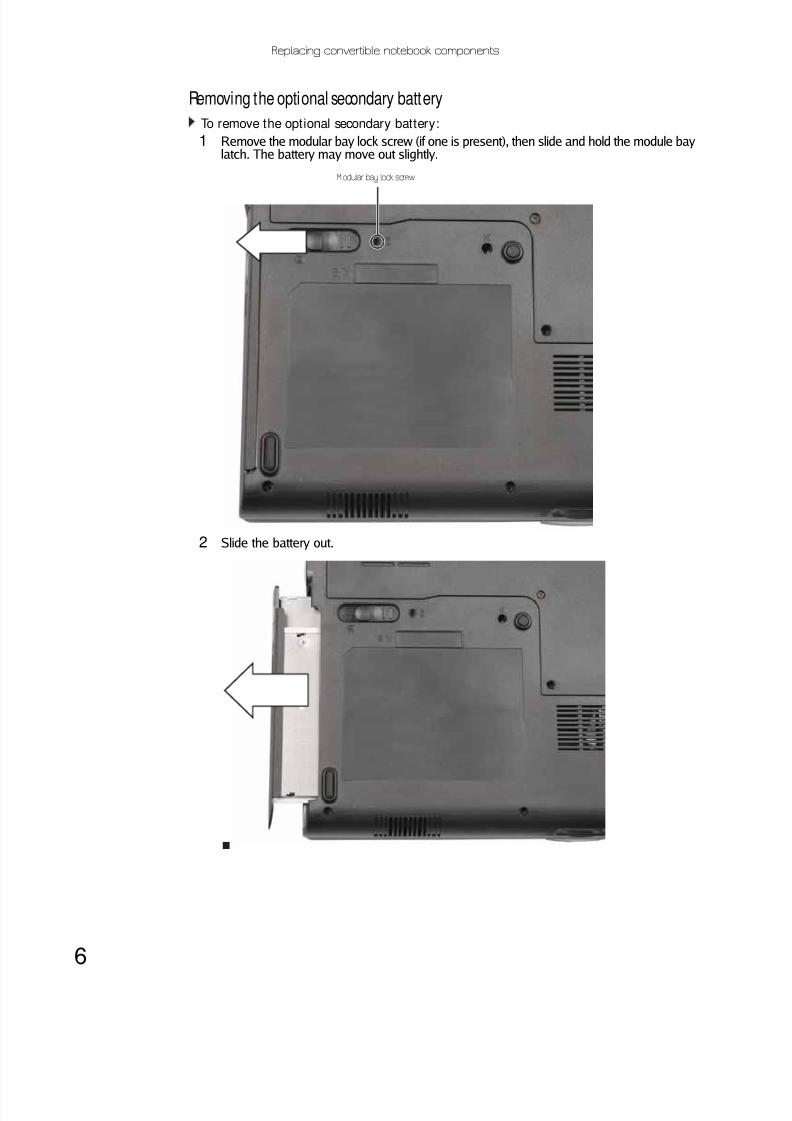
Removing the optional secondary battery
To remove the optional secondary battery:
1 Remove the modular bay lock screw (if one is present), then slide and hold the module baylatch. The battery may move out slightly.
2 Slide the battery out.
Modular bay lock screw

8/12/2019 Viper M280 285 295 Service
http://slidepdf.com/reader/full/viper-m280-285-295-service 11/74
www.gateway.com
7
Replacing a bay moduleTools you need to complete this task:
Screws removed during this task:
To replace a bay module:
1 If you are removing a drive, make sure that there is no disc in it.
2 Complete the steps in “Preparing the convert ible notebook” on page5.
3 Turn the convertible notebook over so the bottom is facing up.
Phillips#0 screwdriver
1 black 2.5*8.0 (Optionalbay module securityscrew)
Modular bay latch
Modular bay
Security screw (optional)

8/12/2019 Viper M280 285 295 Service
http://slidepdf.com/reader/full/viper-m280-285-295-service 12/74
Replacing convertible notebook components
8
4 Remove the modular bay lock screw (if one is present), then slide and hold the module baylatch. The drive may move out slightly.
5 Slide the drive out.
6 Firmly push the new drive straight into the bay until the latch clicks into place.
7 Replace the module bay lock screw.
Modular bay lock screw

8/12/2019 Viper M280 285 295 Service
http://slidepdf.com/reader/full/viper-m280-285-295-service 13/74
www.gateway.com
9
Adding or replacing memory modules
Tools you need to complete this task:
To add or replace memory modules:
1 Complete the steps in “Preparing the convert ible notebook” on page5.
2 Loosen the screws that secure the memory cover. (These screws cannot be removed.)
3 Remove the memory bay cover. Be careful not to break off the tabs located on the bottomof the cover. If the cover does not remove easily, wiggle the cover to loosen it.
ImportantUse only memory modules designed for this Gateway convertible notebook.
Phillips#0 screwdriver
Memory bay
Screw
ScrewScrew Screw
ScrewScrew

8/12/2019 Viper M280 285 295 Service
http://slidepdf.com/reader/full/viper-m280-285-295-service 14/74
Replacing convertible notebook components
10
4 If you are removing a memory module, gently press outward on the clip at each end of themodule until the module tilts upward.
5 Pull the module out of the slot.
6 Hold the new or replacement module at a 30-degree angle and press it into the emptymemory slot. This module is keyed so it can only be inserted in one direction. If the module
does not f it , make sure that the notch in the module lines up with the tab in the memory bay.7 Press the card down until it clicks into place.
8 Replace the memory bay cover, then tighten the cover screws.
ClipClip

8/12/2019 Viper M280 285 295 Service
http://slidepdf.com/reader/full/viper-m280-285-295-service 15/74
www.gateway.com
11
Replacing the cooling assemblyTools you need to complete this task:
v
Additional materials you need to complete this task:
• X-23-7762 thermal grease
To replace the cooling assembly:
1 Complete the steps in “Preparing the convert ible notebook” on page5.
2 Loosen the screws that secure the cooling assembly bay cover. (These screws cannot beremoved.)
Phillips#0 screwdriver
Coolingassembly
bay
Screw
ScrewScrew Screw
ScrewScrew

8/12/2019 Viper M280 285 295 Service
http://slidepdf.com/reader/full/viper-m280-285-295-service 16/74
Replacing convertible notebook components
12
3 Remove the cooling assembly bay cover. Be careful not to break off the tabs located on thebottom of the cover. If the cover does not remove easily, wiggle the cover to loosen it.
4 Loosen the four screws that secure the cooling assembly to the system board. (These screwscannot be removed.) Use the numbers stamped in the metal next to each screw and loosenthe screws in reverse numerical order (start with 4, then 3, then 2, then 1).
5 Loosen the two remaining optional screws that connect the cooling assembly to the systemboard. (These screws cannot be removed.)
6 Disconnect the fan from the system board.
Screw Screw
Screw Screw
Screw
Screw

8/12/2019 Viper M280 285 295 Service
http://slidepdf.com/reader/full/viper-m280-285-295-service 17/74
www.gateway.com
13
7 At the same time as you lif t, move the cooling assembly away from the side of the convert iblenotebook.
8 Remove any thermal grease residue from the processor using a soft cloth and isopropylalcohol.
9 Place new thermal grease on the processor. Use only enough to cover the CPU die.
10 Make sure thermal pads are placed between the cooling assembly and other componentsas shown.
11 Insert the new cooling assembly into the convertible notebook.
12 Connect the fan to the system board.
13 Tighten the two optional screws that connect the cooling assembly to the system board.
14 Tighten the four screws that secure the cooling assembly to the system board. Use thenumbers stamped in the metal next to each screw and t ighten the screws in numerical order(start with 1, then 2, then 3, then 4).
15 Replace the cooling assembly bay cover, then tighten the cover screws.
CautionWhen tightening the cooling assembly’s screws into the numbered holes,
tighten them in numerical order.
Thermalpad
Thermalgrease
Thermalpad

8/12/2019 Viper M280 285 295 Service
http://slidepdf.com/reader/full/viper-m280-285-295-service 18/74
Replacing convertible notebook components
14
Replacing the processorTools you need to complete this task:
v
Additional materials you need to complete this task:
• X-23-7762 thermal grease
To replace the processor:
1 Complete the steps in “Preparing the convert ible notebook” on page5.
2 Remove the cooling assembly by following the steps in “Replacing the cooling assembly” onpage11.
3 Use a flat-blade screwdriver to turn the processor lock screw 1/ 4-turn counter-clockwise.
Phillips#0 screwdriver Flat-blade driver

8/12/2019 Viper M280 285 295 Service
http://slidepdf.com/reader/full/viper-m280-285-295-service 19/74
www.gateway.com
15
4 Remove the old processor from the system board.
5 Install the new processor onto the system board making sure that Pin 1 on the processor(indicated by the silk-screened arrow on the corner of the processor) aligns with Pin 1 onthe processor socket (indicated by the absence of a pin hole in the processor socket), thenuse a flat-blade screwdriver to turn the processor lock screw 1/ 4-turn clockwise.
6 Remove any thermal grease residue from the cooling assembly using a soft cloth andisopropyl alcohol.
7 Place new thermal grease on the processor. Use only enough to cover the CPU die.
8 Make sure thermal pads are placed between the cooling assembly and other componentsas shown.
9 Replace the cooling assembly by following the instructions in “Replacing the coolingassembly” on page 11.
Thermalpad
Thermalgrease
Thermalpad

8/12/2019 Viper M280 285 295 Service
http://slidepdf.com/reader/full/viper-m280-285-295-service 20/74
Replacing convertible notebook components
16
Replacing the IEEE 802.11 wireless cardTools you need to complete this task:
Screws removed during this task:
To replace the IEEE 802.11 wireless card:
1 Complete the steps in “Preparing the convert ible notebook” on page5.
Phillips #0 screwdriver
2 chrome 2.0*3.0(IEEE 802.11 wirelesscard) Select modelsonly
Wireless bay

8/12/2019 Viper M280 285 295 Service
http://slidepdf.com/reader/full/viper-m280-285-295-service 21/74
www.gateway.com
17
2 Loosen the screw that secures the wireless cover. (This screw cannot be removed.)
3 Remove the wireless bay cover. Be careful not to break off the tabs located on the bottomof the cover. If the cover does not remove easily, wiggle the cover to loosen it.
4 Unplug the antenna cables. Note which color cable is connected to each of the connectors.
5 Move the antenna cables out of the way.
ImportantThe number of antenna cables varies by the type of wireless network used
by the convertible notebook. IEEE802.11N cards typically have three antenna cables.Other types of wireless network cards typically have two antenna cables. Someconvertible notebook models do not support three antenna cables.
Screw

8/12/2019 Viper M280 285 295 Service
http://slidepdf.com/reader/full/viper-m280-285-295-service 22/74
Replacing convertible notebook components
18
6 If the wireless card is held by clips, press outward on the clip at each side of the card untilthe card tilts upward.
0
-OR-
If the wireless card is held by screws, remove the screws.
Clip
Clip
Screw
Screw

8/12/2019 Viper M280 285 295 Service
http://slidepdf.com/reader/full/viper-m280-285-295-service 23/74
www.gateway.com
19
7 Pull the card out of the slot.
8 Hold the new card at a 30-degree angle and press it into the empty slot. This card is keyedso it can only be inserted in one direction. If the card does not fit, make sure that the notchin the card lines up with the tab in the card slot.
9 Move the antenna cables out of the way.
10 Press the card down until it clicks into place.
-OR-
Press the card down, then replace the screws removed in Step 6.
11 Reattach the antenna cables to the connectors.12 Replace the wireless bay cover, then tighten the cover screw.

8/12/2019 Viper M280 285 295 Service
http://slidepdf.com/reader/full/viper-m280-285-295-service 24/74
Replacing convertible notebook components
20
Replacing the CMOS battery
Tools you need to complete this task:v
Screws removed during this task:
To replace the CMOS battery:
1 Complete the steps in “Preparing the convert ible notebook” on page5.
2 Open the wireless bay by following the instructions in “Replacing the IEEE 802.11 wirelesscard” on page16. If your convertible notebook has a wireless card, remove it.
3 Locate the old battery on the system board.
4 Insert the small flat-blade screwdriver or non-marring tool under the old battery and gentlypry it up until it pops out of the socket.
5 Make sure the positive (+) side of the new battery is facing up, then press the battery intothe socket until it snaps into place.
6 If the convertible notebook has wireless networking built in, replace the wireless card byfollowing the steps in “Replacing the IEEE 802.11 wireless card” on page 16.
7 Replace the wireless bay cover by following the steps in “Replacing the IEEE 802.11 wirelesscard” on page16.
ImportantUse only CMOS batteries designed for this Gateway convertible notebook.
Flat-blade driver Scribe or non-marring tool- OR -
Phillips#0 screwdriver
2 chrome 2.0*3.0(IEEE 802.11 wirelesscard) Select modelsonly

8/12/2019 Viper M280 285 295 Service
http://slidepdf.com/reader/full/viper-m280-285-295-service 25/74
www.gateway.com
21
Replacing the hard driveTools you need to complete this task:
Screws removed during this task:
To replace the hard drive:
1 Complete the steps in “Preparing the convert ible notebook” on page5.
Phillips#0 screwdriver
1 chrome 2.5*5.0 (Harddrive) 4 chrome 3.0*0.5+3.5I
(Hard drive bracket)
Harddrive

8/12/2019 Viper M280 285 295 Service
http://slidepdf.com/reader/full/viper-m280-285-295-service 26/74
Replacing convertible notebook components
22
2 Loosen the screws that secure the hard drive bay cover. (These screws cannot be removed.)
3 Remove the hard drive bay cover. Be careful not to break off the tabs located on the bottomof the cover. If the cover does not remove easily, wiggle the cover to loosen it.
Screw Screw

8/12/2019 Viper M280 285 295 Service
http://slidepdf.com/reader/full/viper-m280-285-295-service 27/74
www.gateway.com
23
4 Remove the hard drive screw.
Screw

8/12/2019 Viper M280 285 295 Service
http://slidepdf.com/reader/full/viper-m280-285-295-service 28/74
Replacing convertible notebook components
24
5 Slide the old hard drive kit out of the convertible notebook.
6 Remove the four screws that secure the hard drive to the hard drive kit bracket.
7 Insert the new drive into the bracket, label side up, so the screw holes line up.
8 Replace the four screws that were removed in Step 6.
Screw
Screw
Screw
Screw

8/12/2019 Viper M280 285 295 Service
http://slidepdf.com/reader/full/viper-m280-285-295-service 29/74
www.gateway.com
25
9 Slide the new hard drive into your convertible notebook, then replace the screw that wasremoved in Step 4.
10 Replace the hard drive bay cover, then tighten the cover screws.

8/12/2019 Viper M280 285 295 Service
http://slidepdf.com/reader/full/viper-m280-285-295-service 30/74

8/12/2019 Viper M280 285 295 Service
http://slidepdf.com/reader/full/viper-m280-285-295-service 31/74
www.gateway.com
27
Replacing the keyboard coverTools you need to complete this task:
v
To replace the keyboard cover:
1 Complete the steps in “Preparing the convert ible notebook” on page5.
2 Turn the convertible notebook over so the top is facing up.
3 Open the LCD panel to the fully open position.
4 Insert the small flat-blade screwdriver under the bottom of the keyboard cover between thePAUSE and INSERT keys and gently pry it up.
5 Insert the small flat-blade screwdriver under the bottom of the keyboard cover between theF1 and F2 keys and gently pry it up.
6 Remove the keyboard cover from the convertible notebook by pulling the cover toward youand at the same time lifting its front to clear the keyboard. You will hear small snappingsounds as the cover comes away from the convertible notebook. Be careful not to break offthe tabs located on the bottom of the cover.
7 Slide the tabs on the bottom side of the new cover under the convertible notebook frame.
8 Press down on the cover in several places to make sure that it is correctly mounted. Thecover is correctly mounted when you can run your finger along the cover and find no loosespots. The cover should be flat all the way across.
9 Close the LCD panel.
CautionIf the cover is not correctly replaced, the convertible notebook could be
damaged when you try to close the LCD panel.
Flat-blade driver Scribe or non-marring tool- OR -

8/12/2019 Viper M280 285 295 Service
http://slidepdf.com/reader/full/viper-m280-285-295-service 32/74

8/12/2019 Viper M280 285 295 Service
http://slidepdf.com/reader/full/viper-m280-285-295-service 33/74
www.gateway.com
29
4 Lift the back edge of the keyboard slight ly, then slowly slide it toward the LCD panel to releasethe keyboard retaining tabs located on the front edge of the keyboard.
5 Carefully rotate the keyboard toward you so it lies keys-down on top of your convertiblenotebook. Be careful not to damage the LCD panel.
6 Swing the black keyboard connector clip up, then lift the cable out of the connector. Be carefulnot to touch or damage any other components.
7 Place the new keyboard on your convertible notebook.8 Make sure the black keyboard connector clip is up, insert the cable into the connector, thenswing the clip down to lock the connector in place.
ImportantThe keyboard cable is correctly oriented if it is not twisted.
Keyboard connector clip

8/12/2019 Viper M280 285 295 Service
http://slidepdf.com/reader/full/viper-m280-285-295-service 34/74
Replacing convertible notebook components
30
9 Insert the tabs on the front edge of the keyboard into the slots under the palm rest. Youmay need to press down on the keyboard keys along the front edge of the keyboard to seatthe retaining tabs into their corresponding slots.
10 Gently press the keyboard down until it is flat all the way across. The keyboard should easilyfall into place. Be careful to not damage the LCDpanel.
11 Replace the keyboard cover by following the steps in “Replacing the keyboard cover” onpage 27.
12 Close the LCD panel.
13 Turn your convertible notebook over so the bottom is facing up.
14 Replace the screws removed in Step 2.

8/12/2019 Viper M280 285 295 Service
http://slidepdf.com/reader/full/viper-m280-285-295-service 35/74

8/12/2019 Viper M280 285 295 Service
http://slidepdf.com/reader/full/viper-m280-285-295-service 36/74
Replacing convertible notebook components
32
5 Remove the screws from the front of the LCD panel assembly.
6 Carefully separate the front and back of the LCD panel assembly.
7 Disconnect the connectors from the inverter.
8 Remove the screw that connects the inverter to the front of the LCD panel assembly.
ImportantThe number of screws varies by convertible notebook model.
Screw Screw Screw Screw
Screw Screw Screw Screw
Screw

8/12/2019 Viper M280 285 295 Service
http://slidepdf.com/reader/full/viper-m280-285-295-service 37/74

8/12/2019 Viper M280 285 295 Service
http://slidepdf.com/reader/full/viper-m280-285-295-service 38/74
Replacing convertible notebook components
34
Replacing the power button boardTools you need to complete this task:
v
Screws removed during this task:
To replace the power button board:
1 Complete the steps in “Preparing the convert ible notebook” on page5.
2 Remove the keyboard cover by following the steps in “Replacing the keyboard cover” onpage 27.
3 Open the LCD panel to the fully open position.
4 Remove the rubber inserts from the front of the LCD panel assembly.
ImportantThe number of rubber inserts varies by convertible notebook model.
Flat-blade driver Scribe or non-marring tool- OR -
Phillips#0 screwdriver
2 chrome 2.5*6.0(Power button
board)
4 or 8 black 2.5*5.0 (LCDpanel front)
Insert
InsertInsertInsertInsert
InsertInsertInsert
8/12/2019 Viper M280 285 295 Service
http://slidepdf.com/reader/full/viper-m280-285-295-service 39/74
www.gateway.com
35
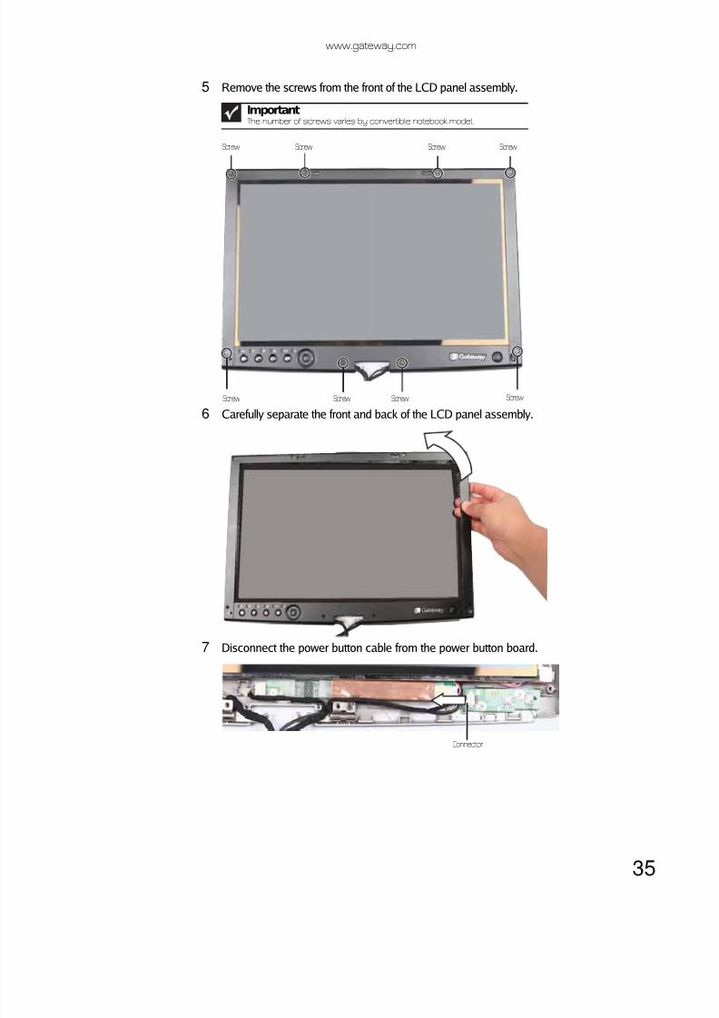
5 Remove the screws from the front of the LCD panel assembly.
6 Carefully separate the front and back of the LCD panel assembly.
7 Disconnect the power button cable from the power button board.
ImportantThe number of screws varies by convertible notebook model.
Screw Screw Screw Screw
Screw Screw Screw Screw
Connector

8/12/2019 Viper M280 285 295 Service
http://slidepdf.com/reader/full/viper-m280-285-295-service 40/74
Replacing convertible notebook components
36
8 Remove the two screws that connect the power button board to the front of the LCD panelassembly, then remove the board.
9 Install the new power button board.
10 Replace the screws that were removed in Step 8, then reconnect the cable.
11 Press the LCD panel front and back together. Press the two halves together in several placesuntil they click in place. You should find no loose spots or spots where the two halves donot meet.
12 Replace the LCD panel assembly screws removed in Step 5.
13 Replace the inserts removed in Step 4.
14 Replace the keyboard cover by following the steps in “Replacing the keyboard cover” onpage 27.
CautionThe larger rubber inserts go across the top of the panel.
Screw Screw

8/12/2019 Viper M280 285 295 Service
http://slidepdf.com/reader/full/viper-m280-285-295-service 41/74
www.gateway.com
37
Replacing the tablet button boardTools you need to complete this task:
v
Screws removed during this task:
To replace the tablet button board:
1 Complete the steps in “Preparing the convert ible notebook” on page5.
2 Remove the keyboard cover by following the steps in “Replacing the keyboard cover” onpage 27.
3 Open the LCD panel to the fully open position.
4 Remove the rubber inserts from the front of the LCD panel assembly.
ImportantThe number of rubber inserts varies by convertible notebook model.
Flat-blade driver Scribe or non-marring tool- OR -
Phillips#0 screwdriver
2 chrome 2.5*6.0(Tablet button board)
4 or 8 black 2.5*5.0 (LCDpanel front)
Insert
InsertInsertInsertInsert
InsertInsertInsert
8/12/2019 Viper M280 285 295 Service
http://slidepdf.com/reader/full/viper-m280-285-295-service 42/74
Replacing convertible notebook components
38
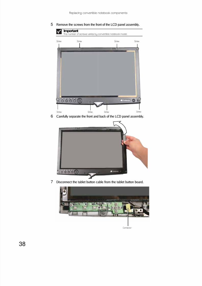
5 Remove the screws from the front of the LCD panel assembly.
6 Carefully separate the front and back of the LCD panel assembly.
7 Disconnect the tablet button cable from the tablet button board.
ImportantThe number of screws varies by convertible notebook model.
Screw Screw Screw Screw
Screw Screw Screw Screw
Connector

8/12/2019 Viper M280 285 295 Service
http://slidepdf.com/reader/full/viper-m280-285-295-service 43/74
www.gateway.com
39
8 Remove the two screws that connect the tablet button board to the front of the LCD panelassembly, then remove the board.
9 Install the new tablet button board.
10 Replace the screws that were removed in Step 8, then reconnect the cable.
11 Press the LCD panel front and back together. Press the two halves together in several placesuntil they click in place. You should find no loose spots or spots where the two halves donot meet.
12 Replace the LCD panel assembly screws removed in Step 5.
13 Replace the inserts removed in Step 4.
14 Replace the keyboard cover by following the steps in “Replacing the keyboard cover” onpage 27.
CautionThe larger rubber inserts go across the top of the panel.
Screw Screw

8/12/2019 Viper M280 285 295 Service
http://slidepdf.com/reader/full/viper-m280-285-295-service 44/74
Replacing convertible notebook components
40
Replacing the LCD assemblyTools you need to complete this task:
v
Screws removed during this task:
To replace the LCD assembly:
1 Complete the steps in “Preparing the convert ible notebook” on page5.
2 If the convertible notebook has wireless networking built in, unplug the wireless antennasby following the steps in “Replacing the IEEE 802.11 wireless card” on page 16.
3 Remove the screws on the bottom that secure the LCD panel hinge to the chassis.
4 Turn the convertible notebook over so the top is facing up.
5 Remove the hinge covers by following the steps in “Replacing the hinge covers” on page 26.
6 Open the LCD panel to the fully open position.
ImportantThe number of screws varies by convertible notebook model.
CautionBe careful not to use too much force when opening the LCD panel.
Flat-blade driver Scribe or non-marring tool- OR -
Phillips#0 screwdriver
4 or 6 black 2.5*8.0 (LCD
hinge to notebook)
Screw
Screw
Screw
Screw

8/12/2019 Viper M280 285 295 Service
http://slidepdf.com/reader/full/viper-m280-285-295-service 45/74
www.gateway.com
41
7 Remove the keyboard cover by following the steps in “Replacing the keyboard cover” onpage 27.
8 Detach the three cables from the system board.
9 Grasp the plastic tab carefully and pull to unplug the LCD video cable from the convertiblenotebook. Make sure you grasp the tab, not the cable.
10 Taking care to note the cables’ routing and positions as they are installed from Gateway,pull the antenna cables out f rom under the system board, then slide the wires out from underthe retaining clips.
11 Remove the two screws on the top that secure the LCD panel hinge to the chassis.
CautionThe connector is fragile.
Screw Screw
8/12/2019 Viper M280 285 295 Service
http://slidepdf.com/reader/full/viper-m280-285-295-service 46/74
Replacing convertible notebook components
42
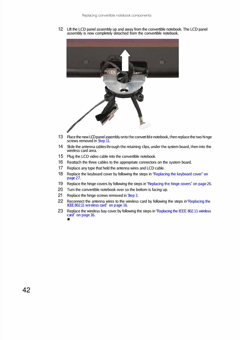
12 Lift the LCD panel assembly up and away from the convertible notebook. The LCD panelassembly is now completely detached from the convertible notebook.
13 Place the new LCD panel assembly onto the convert ible notebook, then replace the two hingescrews removed in Step 11.
14 Slide the antenna cables through the retaining clips, under the system board, then into thewireless card area.
15 Plug the LCD video cable into the convertible notebook.
16 Reattach the three cables to the appropriate connectors on the system board.
17 Replace any tape that held the antenna wires and LCD cable.
18 Replace the keyboard cover by following the steps in “Replacing the keyboard cover” on
page 27.19 Replace the hinge covers by following the steps in “Replacing the hinge covers” on page26.
20 Turn the convertible notebook over so the bottom is facing up.
21 Replace the hinge screws removed in Step 3.
22 Reconnect the antenna wires to the wireless card by following the steps in “Replacing theIEEE 802.11 wireless card” on page 16.
23 Replace the wireless bay cover by following the steps in “Replacing the IEEE 802.11 wirelesscard” on page16.

8/12/2019 Viper M280 285 295 Service
http://slidepdf.com/reader/full/viper-m280-285-295-service 47/74
8/12/2019 Viper M280 285 295 Service
http://slidepdf.com/reader/full/viper-m280-285-295-service 48/74
Replacing convertible notebook components
44
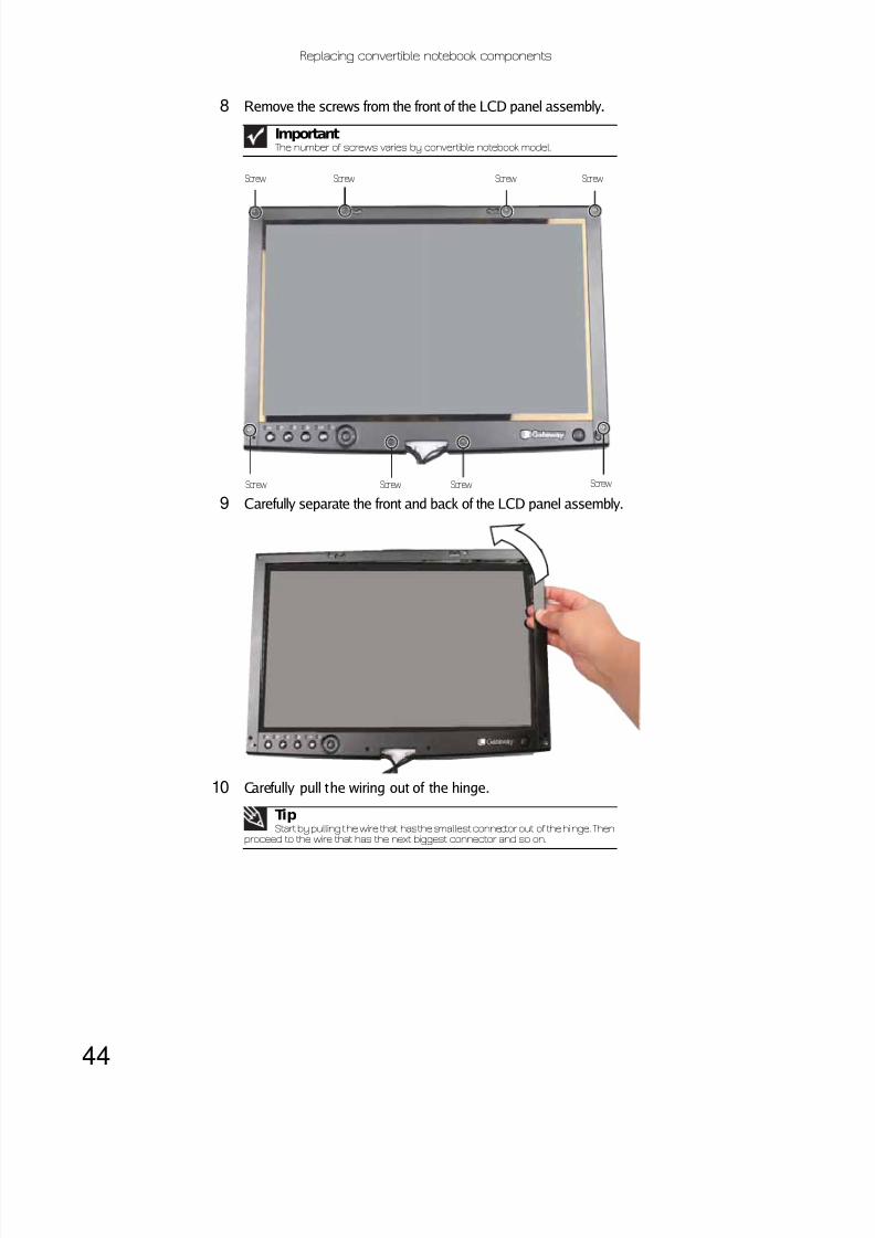
8 Remove the screws from the front of the LCD panel assembly.
9 Carefully separate the front and back of the LCD panel assembly.
10 Carefully pull the wiring out of the hinge.
ImportantThe number of screws varies by convertible notebook model.
TipStart by pulling the wire that has the smallest connector out of the hinge. Then
proceed to the wire that has the next biggest connector and so on.
Screw Screw Screw Screw
Screw Screw Screw Screw

8/12/2019 Viper M280 285 295 Service
http://slidepdf.com/reader/full/viper-m280-285-295-service 49/74
www.gateway.com
45
11 Remove the four screws that secure the old hinge to the LCD panel assembly.
12 Replace the new hinge onto the LCD panel assembly.
13 Replace the screws removed in Step 11.
14 Feed the wiring back into the hinge.
15 Replace the screws that were removed in Step 8, then reconnect the cable.
16 Press the LCD panel front and back together. Press the two halves together in several placesuntil they click in place. You should find no loose spots or spots where the two halves donot meet.
17 Replace the LCD panel assembly screws removed in Step 5.
18 Replace the inserts removed in Step 4.
19 Replace the LCD assembly by following the steps in “Replacing the LCD assembly” on page 40.
20 Replace the keyboard cover by following the steps in “Replacing the keyboard cover” onpage 27.
21 Replace the hinge covers by following the steps in “Replacing the hinge covers” on page26.
22 Reconnect the antenna wires to the wireless card by following the steps in “Replacing theIEEE 802.11 wireless card” on page 16.
23 Replace the wireless bay cover by following the steps in “Replacing the IEEE 802.11 wirelesscard” on page 16.
TipStart by feeding the wire that has the largest connector into the hinge. Then
proceed to the wire that has the next smallest connector and so on.
CautionThe larger rubber inserts go across the top of the panel.
Screws Screws

8/12/2019 Viper M280 285 295 Service
http://slidepdf.com/reader/full/viper-m280-285-295-service 50/74

8/12/2019 Viper M280 285 295 Service
http://slidepdf.com/reader/full/viper-m280-285-295-service 51/74
www.gateway.com
47
9 Remove the screws connecting the LCD panel to the LCD lid.
10 Remove the old LCD panel from the LCD lid.
11Place the new LCD panel into the LCD lid.
12 Replace the screws removed in Step 9.
13 Feed the wiring back into the hinge.
14 Reconnect the tablet button board by following the instructions in “Replacing the tabletbutton board” on page 37.
15 Reconnect the inverter and reassemble the LCD assembly by following the instructions in“Replacing the inverter” on page31.
16 Replace the LCD assembly by following the steps in “Replacing the LCD assembly” on page 40.
17 Replace the keyboard cover by following the steps in “Replacing the keyboard cover” on
page 27.
18 Replace the hinge covers by following the steps in “Replacing the hinge covers” on page26.
19 Reconnect the antenna wires to the wireless card by following the steps in “Replacing theIEEE 802.11 wireless card” on page 16.
20 Replace the wireless bay cover by following the steps in “Replacing the IEEE 802.11 wirelesscard” on page 16.
TipStart by feeding the wire that has the largest connector into the hinge. Then
proceed to the wire that has the next smallest connector and so on.
Screw
Screw
Screw
Screw

8/12/2019 Viper M280 285 295 Service
http://slidepdf.com/reader/full/viper-m280-285-295-service 52/74
Replacing convertible notebook components
48
Replacing the LCD assembly lidTools you need to complete this task:
v
Screws removed during this task:
To replace the LCD assembly lid:
1 Complete the steps in “Preparing the convert ible notebook” on page5.
2 If the convertible notebook has wireless networking built in, unplug the wireless antennasby following the steps in “Replacing the IEEE 802.11 wireless card” on page 16.
3 Remove the hinge covers by following the steps in “Replacing the hinge covers” on page 26.
4 Remove the keyboard cover by following the steps in “Replacing the keyboard cover” onpage 27.
5 Remove the LCD assembly by following the steps in “Replacing the LCD assembly” on page 40.
6 Remove the inverter by following the instructions in “Replacing the inverter” on page31.
7 Remove the power button board by following the instructions in “Replacing the power buttonboard” on page34.
8 Remove the tablet button board by following the instructions in “Replacing the tablet but tonboard” on page37.
Flat-blade driver Scribe or non-marring tool- OR -
Phillips#0 screwdriver
4 or 6 black 2.5*8.0 (LCDhinge to notebook)
4 black 2.5*8.0 (LCDpanel)
4 or 8 black 2.5*5.0 (LCDpanel front)
1 chrome 2.5*2.5(Inverter)
2 chrome 2.5*6.0(Power buttonboard)
2 chrome 2.5*6.0(Tablet button board)
4 black 2.5*3.5 (LCDhinge to LCD panel)

8/12/2019 Viper M280 285 295 Service
http://slidepdf.com/reader/full/viper-m280-285-295-service 53/74
www.gateway.com
49
9 Remove the LCD panel hinge by following the instructions in “Replacing the LCD panel hinge”on page 43.
10 Remove the screws connecting the LCD panel to the old LCD lid.
11 Remove the LCD panel from the old LCD lid.
12 Place the LCD panel into the new LCD lid.
13 Replace the screws removed in Step 10.
14 Replace the LCD panel hinge by following the instructions in “Replacing the LCD panel hinge”on page 43.
15 Replace the tablet but ton board by following the instructions in “Replacing the tablet buttonboard” on page37.
16 Replace the power button board by following the instructions in “Replacing the power buttonboard” on page34.
17 Replace the inverter and reassemble the LCD assembly by following the instructions in“Replacing the inverter” on page31.
18 Replace the LCD assembly by following the steps in “Replacing the LCD assembly” on page 40.19 Replace the keyboard cover by following the steps in “Replacing the keyboard cover” on
page 27.
20 Replace the hinge covers by following the steps in “Replacing the hinge covers” on page26.
21 Reconnect the antenna wires to the wireless card by following the steps in “Replacing theIEEE 802.11 wireless card” on page 16.
22 Replace the wireless bay cover by following the steps in “Replacing the IEEE 802.11 wirelesscard” on page 16.
Screw
Screw
Screw
Screw

8/12/2019 Viper M280 285 295 Service
http://slidepdf.com/reader/full/viper-m280-285-295-service 54/74
Replacing convertible notebook components
50
Replacing the palm restTools you need to complete this task:
v
Screws removed during this task:
To replace the palm rest:
1 Complete the steps in “Preparing the convert ible notebook” on page5.
2 Remove the bay module by following the steps in “Replacing a bay module” on page7.
3 If the convertible notebook has wireless networking built in, unplug the wireless antennasby following the steps in “Replacing the IEEE 802.11 wireless card” on page 16.
4 Remove the hard drive by following the steps in “Replacing the hard drive” on page21.5 Remove the hinge covers by following the steps in “Replacing the hinge covers” on page 26.
6 Remove the keyboard cover by following the steps in “Replacing the keyboard cover” onpage 27.
7 Remove the keyboard by following the steps in “Replacing the keyboard” on page 28.
8 Remove the LCD assembly by following the steps in “Replacing the LCD assembly” on page 40.
Flat-blade driver Scribe or non-marring tool- OR -
Phillips#0 screwdriver
1 black 2.5*8.0 (Optionalbay module securityscrew)
1 chrome 2.5*5.0 (Harddrive)
2 chrome 2.0*5.0(palm rest-hard drivebay)
3 chrome 2.0-0.4*2.0(palm rest-modulardrive bay) 1 black 2.5*8.0 (palm
rest-top)
14-16 black 2.5*8.0(palm rest-bottom)
2 black 2.5*8.0(Keyboard)
4 or 6 black 2.5*8.0 (LCDhinge to notebook)
2 chrome 2.0*3.0(Fingerprint reader)

8/12/2019 Viper M280 285 295 Service
http://slidepdf.com/reader/full/viper-m280-285-295-service 55/74
www.gateway.com
51
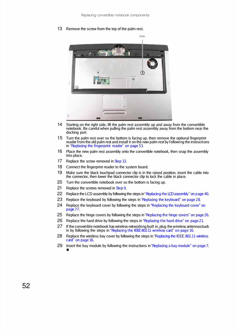
9 Remove the screws shown in the following picture. Note the location of the screw types andsizes. Some models may have fewer screws than shown or screws in a slightly differentlocation.
10 Turn the convertible notebook over so the top is facing up.
11 Flip the black touchpad connector clip up, then remove the cable. Be careful not to touch ordamage any other components.
12 Disconnect the optional fingerprint reader from the system board.
ImportantThe number of screws varies by convertible notebook model.
Screws
Screws
Screws
Screws
Touchpad connectorFingerprint reader connector
8/12/2019 Viper M280 285 295 Service
http://slidepdf.com/reader/full/viper-m280-285-295-service 56/74

8/12/2019 Viper M280 285 295 Service
http://slidepdf.com/reader/full/viper-m280-285-295-service 57/74
www.gateway.com
53
Replacing the fingerprint readerTools you need to complete this task:
v
Screws removed during this task:
To replace the fingerprint reader:
1 Complete the steps in “Preparing the convert ible notebook” on page5.
2 Remove the bay module by following the steps in “Replacing a bay module” on page7.
3 If the convertible notebook has wireless networking built in, unplug the wireless antennasby following the steps in “Replacing the IEEE 802.11 wireless card” on page 16.
4 Remove the hard drive by following the steps in “Replacing the hard drive” on page21.
5 Remove the keyboard cover by following the steps in “Replacing the keyboard cover” onpage 27.
6 Remove the keyboard by following the steps in “Replacing the keyboard” on page 28.
7 Remove the LCD assembly by following the steps in “Replacing the LCD assembly” on page40.
8 Remove the palm rest by following the steps in “Replacing the palm rest” on page50.
9 Turn the palm rest over so the back side is facing up.
Flat-blade driver Scribe or non-marring tool- OR -
Phillips#0 screwdriver
1 black 2.5*8.0 (Optionalbay module securityscrew)
1 chrome 2.5*5.0 (Harddrive)
2 chrome 2.0*3.0(Fingerprint reader)
2 black 2.5*8.0(Keyboard)
4 or 6 black 2.5*8.0 (LCDhinge to notebook)
14-16 black 2.5*8.0(palm rest-bottom)
2 chrome 2.0*5.0(palm rest-hard drivebay)
3 chrome 2.0-0.4*2.0(palm rest-modulardrive bay) 1 black 2.5*8.0 (palm
rest-top)
8/12/2019 Viper M280 285 295 Service
http://slidepdf.com/reader/full/viper-m280-285-295-service 58/74
Replacing convertible notebook components
54
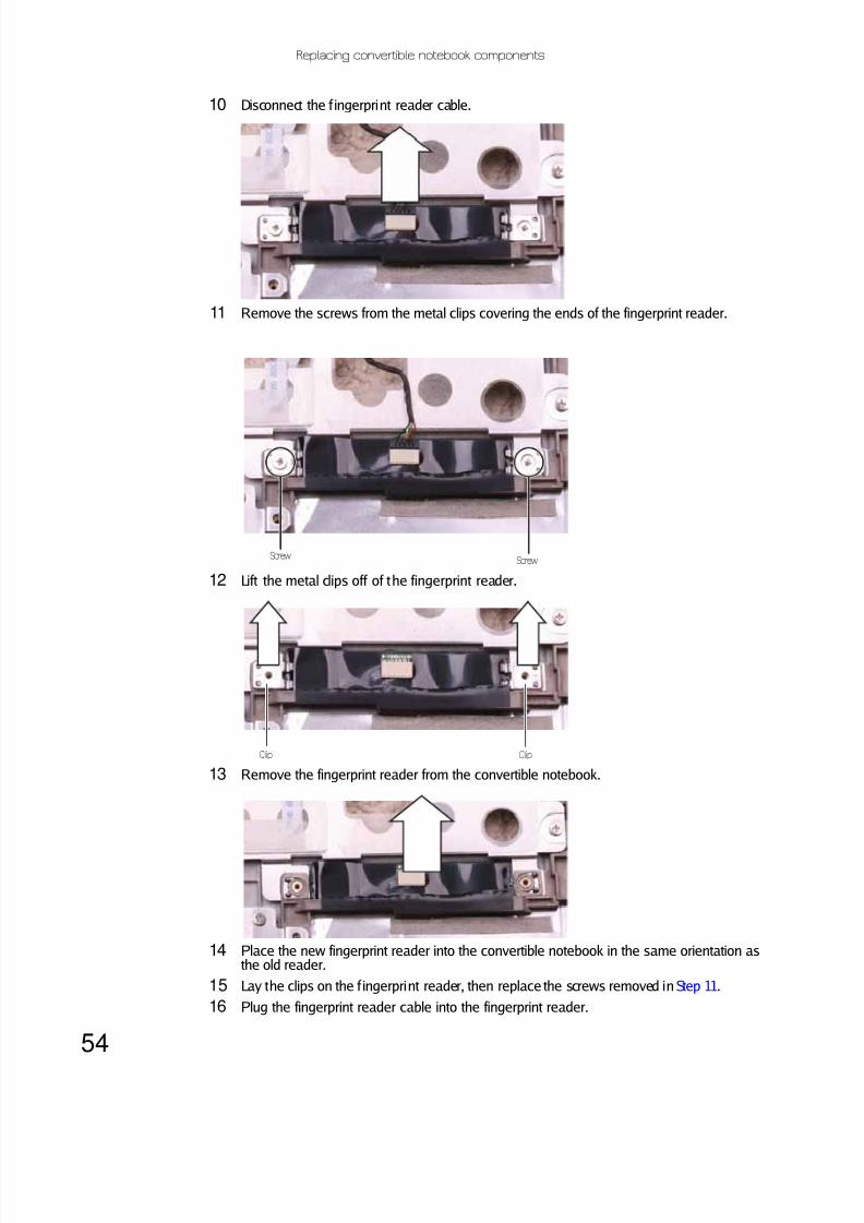
10 Disconnect the f ingerprint reader cable.
11 Remove the screws from the metal clips covering the ends of the fingerprint reader.
12 Lift the metal clips off of the fingerprint reader.
13 Remove the fingerprint reader from the convertible notebook.
14 Place the new fingerprint reader into the convertible notebook in the same orientation asthe old reader.
15 Lay the clips on the f ingerprint reader, then replace the screws removed in Step 11.
16 Plug the fingerprint reader cable into the fingerprint reader.
ScrewScrew
Clip Clip

8/12/2019 Viper M280 285 295 Service
http://slidepdf.com/reader/full/viper-m280-285-295-service 59/74
8/12/2019 Viper M280 285 295 Service
http://slidepdf.com/reader/full/viper-m280-285-295-service 60/74
Replacing convertible notebook components
56
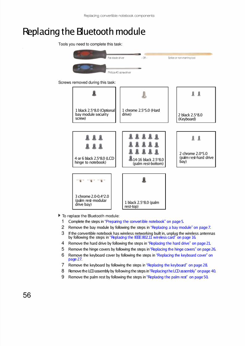
Replacing the Bluetooth moduleTools you need to complete this task:
v
Screws removed during this task:
To replace the Bluetooth module:
1 Complete the steps in “Preparing the convert ible notebook” on page5.
2 Remove the bay module by following the steps in “Replacing a bay module” on page7.
3 If the convertible notebook has wireless networking built in, unplug the wireless antennasby following the steps in “Replacing the IEEE 802.11 wireless card” on page 16.
4 Remove the hard drive by following the steps in “Replacing the hard drive” on page21.
5 Remove the hinge covers by following the steps in “Replacing the hinge covers” on page 26.
6 Remove the keyboard cover by following the steps in “Replacing the keyboard cover” onpage 27.
7 Remove the keyboard by following the steps in “Replacing the keyboard” on page 28.
8 Remove the LCD assembly by following the steps in “Replacing the LCD assembly” on page 40.
9 Remove the palm rest by following the steps in “Replacing the palm rest” on page50.
Flat-blade driver Scribe or non-marring tool- OR -
Phillips#0 screwdriver
1 black 2.5*8.0 (Optionalbay module securityscrew)
1 chrome 2.5*5.0 (Harddrive) 2 black 2.5*8.0
(Keyboard)
4 or 6 black 2.5*8.0 (LCDhinge to notebook)
14-16 black 2.5*8.0(palm rest-bottom)
2 chrome 2.0*5.0(palm rest-hard drivebay)
3 chrome 2.0-0.4*2.0(palm rest-modulardrive bay) 1 black 2.5*8.0 (palm
rest-top)

8/12/2019 Viper M280 285 295 Service
http://slidepdf.com/reader/full/viper-m280-285-295-service 61/74
www.gateway.com
57
10 Disconnect the cable from the old Bluetooth module, then slide the module from theconvertible notebook.
11 Slide the new Bluetooth module into the convertible notebook.
12 Connect the cable to the new Bluetooth module.
13 Replace the palm rest by following the steps in “Replacing the palm rest” on page50.
14 Replace the LCD assembly by following the steps in “Replacing the LCD assembly” on page 40.
15 Replace the keyboard by following the steps in “Replacing the keyboard” on page 28.
16 Replace the keyboard cover by following the steps in “Replacing the keyboard cover” onpage 27.
17 Replace the hinge covers by following the steps in “Replacing the hinge covers” on page26.
18 Replace the hard drive by following the steps in “Replacing the hard drive” on page21.
19 If the convert ible notebook has wireless networking built in, plug the wireless antennas backin by following the steps in “Replacing the IEEE 802.11 wireless card” on page 16.
20Replace the wireless bay cover by following the steps in “Replacing the IEEE 802.11 wirelesscard” on page 16.
21 Insert the bay module by following the instructions in “Replacing a bay module” on page 7.

8/12/2019 Viper M280 285 295 Service
http://slidepdf.com/reader/full/viper-m280-285-295-service 62/74
Replacing convertible notebook components
58
Replacing the system boardTools you need to complete this task:
v
Additional materials you need to complete this task:
• X-23-7762 thermal grease
Screws removed during this task:
To replace the system board:
1 Complete the steps in “Preparing the convert ible notebook” on page5.
2 Remove the bay module by following the instructions in “Replacing a bay module” on page 7.
3 Remove the memory from the old system board and install it on the new system board byfollowing the instructions in “Adding or replacing memory modules” on page 9.
Flat-blade driver Scribe or non-marring tool- OR -
Phillips#0 screwdriver 5.0mm hex nutdriver
1 black 2.5*8.0 (Optionalbay module securityscrew)
1 chrome 2.5*5.0 (Harddrive)
2-4 black 2.5*5.0 (Systemboard)
2 chrome 2.0*2.5(modem)
2 chrome 2.0*3.0(IEEE 802.11 wirelesscard) Select modelsonly
2 black 2.0*2.5 (TPMmodule)
2 black 2.5*8.0(Keyboard)
4 or 6 black 2.5*8.0 (LCDhinge to notebook)
14-16 black 2.5*8.0(palm rest-bottom)
2 chrome 2.0*5.0(palm rest-hard drivebay)
3 chrome 2.0-0.4*2.0(palm rest-modulardrive bay)
1 black 2.5*8.0 (palmrest-top)

8/12/2019 Viper M280 285 295 Service
http://slidepdf.com/reader/full/viper-m280-285-295-service 63/74
www.gateway.com
59
4 Remove the cooling assembly by following the instructions in “Replacing the coolingassembly” on page 11.
5 If your new system board does not include a processor, remove the processor from the oldsystem board and install it on the new system board by following the instructions in“Replacing the processor” on page 14.
6 Remove the optional IEEE 802.11 wireless card from the old system board and install it onthe new system board by following the instructions in “Replacing the IEEE 802.11 wirelesscard” on page 16.
7 If the optional TPM module is located in the wireless bay, remove it from the old systemboard and install it on the new system board by following the instructions in “Replacing theTPM module (select models)” on page 66.
8 Remove the hard drive by following the instructions in “Replacing the hard drive” on page21.
9 Remove the hinge covers by following the steps in “Replacing the hinge covers” on page 26.
10 Remove the keyboard cover by following the steps in “Replacing the keyboard cover” onpage 27.
11 Remove the keyboard by following the steps in “Replacing the keyboard” on page 28.
12 Remove the LCD assembly by following the steps in “Replacing the LCD assembly” on page40.
13 Remove the palm rest by following the steps in “Replacing the palm rest” on page50.
14 Unplug the optional fan from the system board (one connector).

8/12/2019 Viper M280 285 295 Service
http://slidepdf.com/reader/full/viper-m280-285-295-service 64/74
Replacing convertible notebook components
60
15 Unplug the speakers from the system board (one connector).
16 Unplug the Bluetooth module from the system board (one connector).
Speaker connector

8/12/2019 Viper M280 285 295 Service
http://slidepdf.com/reader/full/viper-m280-285-295-service 65/74
www.gateway.com
61
17 Remove the system board screws.
18 Carefully remove the system board.
19 Turn the system board over so the bottom is facing up, then remove the modem from theold system board and install it on the new system board by following the instructions in“Replacing the modem” on page63.
20 If the optional TPM module is located on the bottom of the system board, remove it fromthe old system board and install it on the new system board by following the instructionsin “Replacing the TPM module (select models)” on page 67.
21 Place the new system board into the convertible notebook and reconnect all cables.
22 Replace the system board screws in the holes on the top of the system board removed inStep 17.
23 Connect the Bluetooth module to the system board.
24 Connect the speakers to the system board.
25 Connect the optional fan to the system board.
ImportantThe number of screws varies by convertible notebook model.
ScrewScrewScrew
Screw

8/12/2019 Viper M280 285 295 Service
http://slidepdf.com/reader/full/viper-m280-285-295-service 66/74
Replacing convertible notebook components
62
26 Replace the palm rest by following the steps in “Replacing the palm rest” on page50.
27 Replace the LCD assembly by following the steps in “Replacing the LCD assembly” on page 40.
28 Replace the keyboard by following the steps in “Replacing the keyboard” on page 28.
29 Replace the keyboard cover by following the steps in “Replacing the keyboard cover” onpage 27.
30 Replace the hinge covers by following the steps in “Replacing the hinge covers” on page26.
31 Replace the hard drive by following the instructions in “Replacing the hard drive” on page 21.
32 Replace the cooling assembly by following the instructions in “Replacing the coolingassembly” on page 11.
33 If the convertible notebook has wireless networking built in, plug the wireless antennas backin by following the steps in “Replacing the IEEE 802.11 wireless card” on page 16.
34 Replace the wireless bay cover by following the steps in “Replacing the IEEE 802.11 wirelesscard” on page16.
35 Insert the bay module by following the instructions in “Replacing a bay module” on page7.

8/12/2019 Viper M280 285 295 Service
http://slidepdf.com/reader/full/viper-m280-285-295-service 67/74
www.gateway.com
63
Replacing the modemTools you need to complete this task:
v
Screws removed during this task:
To replace the modem:1 Complete the steps in “Preparing the convert ible notebook” on page5.
2 Remove the bay module by following the instructions in “Replacing a bay module” on page 7.
3 If the convertible notebook has wireless networking built in, unplug the wireless antennasby following the steps in “Replacing the IEEE 802.11 wireless card” on page 16.
4 Remove the hard drive by following the instructions in “Replacing the hard drive” on page21.
5 Remove the hinge covers by following the steps in “Replacing the hinge covers” on page 26.
6 Remove the keyboard cover by following the steps in “Replacing the keyboard cover” onpage 27.
Flat-blade driver Scribe or non-marring tool- OR -
Phillips#0 screwdriver 5.0mm hex nutdriver
1 black 2.5*8.0 (Optionalbay module securityscrew)
1 chrome 2.5*5.0 (Harddrive)
2-4 black 2.5*5.0 (Systemboard)
2 chrome 2.0*2.5(modem)
2 black 2.5*8.0(Keyboard)
4 or 6 black 2.5*8.0 (LCDhinge to notebook)
14-16 black 2.5*8.0(palm rest-bottom)
2 chrome 2.0*5.0(palm rest-hard drivebay)
3 chrome 2.0-0.4*2.0(palm rest-modulardrive bay) 1 black 2.5*8.0 (palm
rest-top)

8/12/2019 Viper M280 285 295 Service
http://slidepdf.com/reader/full/viper-m280-285-295-service 68/74
Replacing convertible notebook components
64
7 Remove the keyboard by following the steps in “Replacing the keyboard” on page 28.
8 Remove the LCD assembly by following the steps in “Replacing the LCD assembly” on page 40.
9 Remove the palm rest by following the steps in “Replacing the palm rest” on page50.
10 Remove the system board by following the steps in “Replacing the system board” on page58.
11 Turn the system board over so the bottom is facing up, then remove the screws that securethe modem to the convertible notebook.
12 Lift the modem off of the system board.
Screw
Screw
8/12/2019 Viper M280 285 295 Service
http://slidepdf.com/reader/full/viper-m280-285-295-service 69/74
www.gateway.com
65
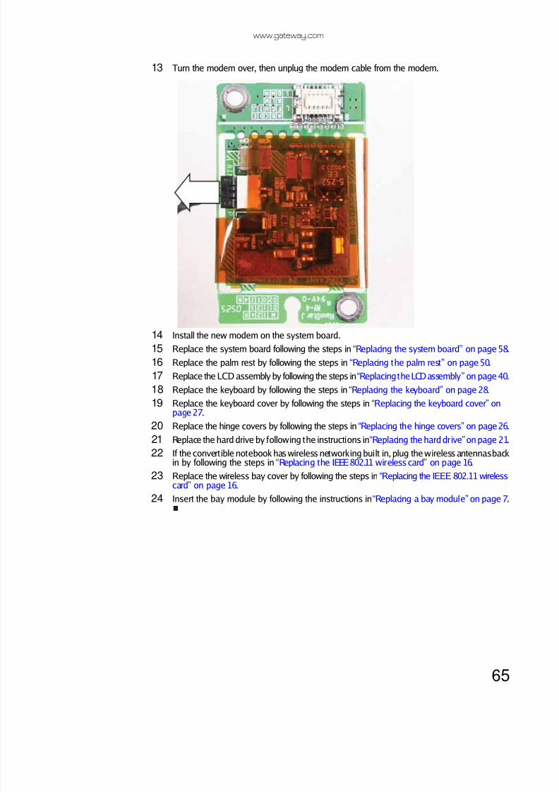
13 Turn the modem over, then unplug the modem cable from the modem.
14 Install the new modem on the system board.
15 Replace the system board following the steps in “Replacing the system board” on page 58.
16 Replace the palm rest by following the steps in “Replacing the palm rest” on page50.
17 Replace the LCD assembly by following the steps in “Replacing the LCD assembly” on page 40.
18 Replace the keyboard by following the steps in “Replacing the keyboard” on page 28.
19 Replace the keyboard cover by following the steps in “Replacing the keyboard cover” on
page 27.20 Replace the hinge covers by following the steps in “Replacing the hinge covers” on page26.
21 Replace the hard drive by following the instructions in “Replacing the hard drive” on page 21.
22 If the convert ible notebook has wireless networking built in, plug the wireless antennas backin by following the steps in “Replacing the IEEE 802.11 wireless card” on page 16.
23 Replace the wireless bay cover by following the steps in “Replacing the IEEE 802.11 wirelesscard” on page 16.
24 Insert the bay module by following the instructions in “Replacing a bay module” on page 7.

8/12/2019 Viper M280 285 295 Service
http://slidepdf.com/reader/full/viper-m280-285-295-service 70/74
Replacing convertible notebook components
66
Replacing the TPM module (select models)
Tools you need to complete this task:v
Screws removed during this task:
To replace the TPM module:
1 Complete the steps in “Preparing the convert ible notebook” on page5.
2 Open the wireless bay by following the instructions in “Replacing the IEEE 802.11 wirelesscard” on page16.
3 Remove the two screws that secure the TPM module to the system board.
4 Lift the TPM module from the system board.
5 Install the new TPM module onto the system board.
6 Replace the TPM module screws removed in Step 3.
7 Replace the wireless bay cover, then tighten the cover screw.
ImportantIf the TPM module is not located in the wireless bay, use the procedure found in
“Replacing the TPM module (select models)” on page67 to replace the TPM module.
Flat-blade driver Scribe or non-marring tool- OR -
Phillips#0 screwdriver
2 black 2.0*2.5 (TPMmodule)
Screw
Screw

8/12/2019 Viper M280 285 295 Service
http://slidepdf.com/reader/full/viper-m280-285-295-service 71/74
www.gateway.com
67
Replacing the TPM module (select models)
Tools you need to complete this task:v
Screws removed during this task:
To replace the TPM module:
1 Complete the steps in “Preparing the convert ible notebook” on page5.
2 Remove the bay module by following the instructions in “Replacing a bay module” on page 7.
3 If the convertible notebook has wireless networking built in, unplug the wireless antennasby following the steps in “Replacing the IEEE 802.11 wireless card” on page 16.
4 Remove the hard drive by following the instructions in “Replacing the hard drive” on page21.
ImportantIf the TPM module is located in the wireless bay, use the procedure found in “Replacing
the TPM module (select models)” on page 66 to replace the TPM module.
Flat-blade driver Scribe or non-marring tool- OR -
Phillips#0 screwdriver 5.0mm hex nutdriver
1 black 2.5*8.0 (Optionalbay module securityscrew)
1 chrome 2.5*5.0 (Harddrive)
2-4 black 2.5*5.0 (Systemboard)
2 black 2.0*2.5 (TPMmodule)
2 black 2.5*8.0(Keyboard)
4 or 6 black 2.5*8.0 (LCDhinge to notebook)
14-16 black 2.5*8.0(palm rest-bottom)
2 chrome 2.0*5.0(palm rest-hard drivebay)
3 chrome 2.0-0.4*2.0(palm rest-modulardrive bay) 1 black 2.5*8.0 (palm
rest-top)

8/12/2019 Viper M280 285 295 Service
http://slidepdf.com/reader/full/viper-m280-285-295-service 72/74
Replacing convertible notebook components
68
5 Remove the hinge covers by following the steps in “Replacing the hinge covers” on page 26.
6 Remove the keyboard cover by following the steps in “Replacing the keyboard cover” onpage 27.
7 Remove the keyboard by following the steps in “Replacing the keyboard” on page 28.
8 Remove the LCD assembly by following the steps in “Replacing the LCD assembly” on page 40.
9 Remove the palm rest by following the steps in “Replacing the palm rest” on page50.
10 Remove the system board by following the steps in “Replacing the system board” on page58.
11 Turn the system board over so the back side is facing up, then remove the two screws thatsecure the TPM module to the system board.
12 Lift the old TPM module from the system board.
13 Install the new TPM module onto the system board.
14 Replace the TPM module screws removed in Step 11.
15 Replace the system board following the steps in “Replacing the system board” on page 58.
16 Replace the palm rest by following the steps in “Replacing the palm rest” on page50.
17 Replace the LCD assembly by following the steps in “Replacing the LCD assembly” on page 40.
18 Replace the keyboard by following the steps in “Replacing the keyboard” on page 28.
19 Replace the keyboard cover by following the steps in “Replacing the keyboard cover” onpage 27.
20 Replace the hinge covers by following the steps in “Replacing the hinge covers” on page26.
21 Replace the hard drive by following the instructions in “Replacing the hard drive” on page 21.
22 If the convertible notebook has wireless networking built in, plug the wireless antennas backin by following the steps in “Replacing the IEEE 802.11 wireless card” on page 16.
23 Replace the wireless bay cover by following the steps in “Replacing the IEEE 802.11 wireless
card” on page16.24 Insert the bay module by following the instructions in “Replacing a bay module” on page7.
Copyright© 2007 Gateway, Inc. All rights reserved. Gateway, Gateway Country, the Gateway stylized logo,and the black-and-white spot design are trademarks or registered trademarks of Gateway, Inc. inthe United States and other countries. All other brands and product names are trademarks orregistered trademarks of their respective companies.
Screw Screw

8/12/2019 Viper M280 285 295 Service
http://slidepdf.com/reader/full/viper-m280-285-295-service 73/74

8/12/2019 Viper M280 285 295 Service
http://slidepdf.com/reader/full/viper-m280-285-295-service 74/74