Embed Size (px)
Citation preview

BandLuxe® M280 Series HSUPA Module Datasheet
1
BandLuxe® M280 Series HSUPA Module Datasheet (3.3V standard version)

BandLuxe® M280 Series HSUPA Module Datasheet
2
Class: Datasheet Doc. No.: M280-D-001 Doc. Version: 1.2 Publish Date: 2009-Dec-24
THE SPECIFICATIONS AND INFORMATION REGARDING THE PRODUCTS IN THIS MANUAL ARE SUBJECT TO CHANGE WITHOUT NOTICE. ALL STATEMENTS, INFORMATION, AND RECOMMENDATIONS IN THIS MANUAL ARE BELIEVED TO BE ACCURATE BUT ARE PRESENTED WITHOUT WARRANTY OF ANY KIND, EXPRESS OR IMPLIED. USERS MUST TAKE FULL RESPONSIBILITY FOR THEIR APPLICATION OF ANY PRODUCTS.
THE SOFTWARE LICENSE AND LIMITED WARRANTY FOR THE ACCOMPANYING PRODUCT ARE SET FORTH IN THE INFORMATION PACKET THAT SHIPPED WITH THE PRODUCT AND ARE INCORPORATED HEREIN BY THIS REFERENCE.
NOTWITHSTANDING ANY OTHER WARRANTY HEREIN, ALL DOCUMENT FILES AND SOFTWARE OF THESE SUPPLIERS ARE PROVIDED “AS IS” WITH ALL FAULTS. PRODUCT AND THE ABOVE-NAMED SUPPLIERS DISCLAIM ALL WARRANTIES, EXPRESSED OR IMPLIED, INCLUDING, WITHOUT LIMITATION, THOSE OF MERCHANTABILITY, FITNESS FOR A PARTICULAR PURPOSE AND NONINFRINGEMENT OR ARISING FROM A COURSE OF DEALING, USAGE, OR TRADE PRACTICE.
IN NO EVENT SHALL PRODUCT OR ITS SUPPLIERS BE LIABLE FOR ANY INDIRECT, SPECIAL, CONSEQUENTIAL, OR INCIDENTAL DAMAGES, INCLUDING, WITHOUT LIMITATION, LOST PROFITS OR LOSS OR DAMAGE TO DATA ARISING OUT OF THE USE OR INABILITY TO USE THIS MANUAL, EVEN IF PRODUCT OR ITS SUPPLIERS HAVE BEEN ADVISED OF THE POSSIBILITY OF SUCH DAMAGES.
BandRich M280 Datasheet Document Number: M280-D-001
BandRich Inc. 8F., No. 188, Baociao Rd., Sindian City TAIPEI, TAIWAN, R.O.C. http://www.bandrich.com
COPYRIGHT ©2007-2008 BandRich All rights reserved.

BandLuxe® M280 Series HSUPA Module Datasheet
3
Revision History
Revision Date Description 1.0 2010-02-25 Draft Document Creation

BandLuxe® M280 Series HSUPA Module Datasheet
4
Table of Contents
Section 1 Introduction .............................................................................................................. 7
1.1 General Description ................................................................................................... 7 1.2 Features......................................................................................................................... 8
1.2.1 WCDMA.............................................................................................................. 8 1.2.2 E-GPRS .............................................................................................................. 8 1.2.3 Baseband Functionality ................................................................................ 8 1.2.4 Software Functionality .................................................................................. 8
Section 2 Interface Description.............................................................................................. 9 2.1 M280 Block Diagram .................................................................................................. 9 2.2 M280 PCI-Express Mini Card Interface ............................................................... 10
2.2.1 Pin Description .............................................................................................. 10 2.2.2 System Interface Signals............................................................................ 11 2.2.3 Power Source and Ground......................................................................... 12
2.3 Network LED indicate device ................................................................................ 13 2.4 USB Interface ............................................................................................................. 14 2.5 USIM Interface............................................................................................................ 14 2.6 Auxiliary Signals Interface ..................................................................................... 15
2.6.1 WAKE# ............................................................................................................. 15 2.6.2 W_DISABLE# ................................................................................................. 15 2.6.3 PERST# ............................................................................................................ 16
2.7 Antenna Guidelines and RF Connection............................................................ 17 2.7.1 Antenna specifications ............................................................................... 17 2.7.2 WLAN Antenna Isolation ............................................................................ 17 2.7.3 Antenna connector....................................................................................... 18
2.8 PCM Interface............................................................................................................. 18 Section 3 Device Driver Interface ........................................................................................ 19 Section 4 AT Command Set Reference.............................................................................. 21 Section 5 Physical Characteristics ..................................................................................... 23
5.1 Dimensions................................................................................................................. 23 5.2 DC Electrical Specification..................................................................................... 25
5.2.1 Absolute Maximum Ratings....................................................................... 25 5.2.2 Recommended Operating Conditions .................................................... 25 5.2.3 DC Characteristics ....................................................................................... 26
5.3 RF System Specification......................................................................................... 27 5.3.1 WCDMA Power .............................................................................................. 27 5.3.2 WCDMA Sensitivity ...................................................................................... 27 5.3.3 GSM Power/Sensitivity................................................................................ 27 5.3.4 Power Consumption .................................................................................... 28
5.4 Thermal Dissipation ................................................................................................. 28 Section 6 Packing Information ............................................................................................. 29 Appendix A Abbreviations and Acronyms ........................................................................ 31 Appendix B BandLuxe AT Command API .......................................................................... 33 Appendix C BandLuxe Proprietary AT Command API ................................................... 38 Appendix D Call Related Standard AT Command API and............................................ 40

BandLuxe® M280 Series HSUPA Module Datasheet
5
List of Figures
Figure 1-1 Top View................................................................................................................................................7 Figure 1-2 Bottom View..........................................................................................................................................7 Figure 2-1 M280 Block Diagram ............................................................................................................................9 Figure 2-2 USB Interface ......................................................................................................................................14 Figure 2-3 USIM Circuits Reference.....................................................................................................................15 Figure 2-4 System Sleep Mode On/Off Level-Trigger .........................................................................................16 Figure 2-5 Module Reset .......................................................................................................................................16 Figure 2-6 Antenna Connector Position and Type................................................................................................18 Figure 5-1 M280 Dimensioned View....................................................................................................................23
BandLuxe® M280 Series HSUPA Module Datasheet
6
List of Tables
Table 1-1 Firmware Version Information ......................................................................................................................... 8 Table 2-1 M280 Module Series Connector Pin-out ....................................................................................................... 10 Table 2-2 System Interface Signals ................................................................................................................................ 11 Table 2-3 LED Output.................................................................................................................................................... 13 Table 2-4 SIM Card Pin Definition................................................................................................................................ 14 Table 2-5 Radio Operational States ................................................................................................................................ 16 Table 5-1 M280 Dimensions.......................................................................................................................................... 23 Table 5-2 M280 and M280V Electrical Specification ................................................................................................... 25 Table 5-3 M280 and M280V Recommended Operating Conditions ............................................................................. 25 Table 5-4 DC Characteristics, Vdd=2.6V ...................................................................................................................... 26 Table 5-5 WCDMA Power Specification....................................................................................................................... 27 Table 5-6 WCDMA Sensitivity Specification................................................................................................................ 27 Table 5-7 GSM Power / Sensitivity Specification ......................................................................................................... 27 Table 5-8 M280 Power Consumption ............................................................................................................................ 28 Table A-1 Abbreviations and Acronyms Table ............................................................................................................... 31 Table B-1 Abbreviations and Acronyms Table ............................................................................................................... 33

BandLuxe® M280 Series HSUPA Module Datasheet
7
Section 1 Introduction
1.1 General Description
The M280 module series is PCI Express Mini Card providing WWAN (HSUPA, HSDPA, WCDMA, EGPRS) connectivity to laptops or any other device equipped with a PCI Express Mini Card slot.
Figure 1-1 Top View
Figure 1-2 Bottom View

BandLuxe® M280 Series HSUPA Module Datasheet
8
1.2 Features
1.2.1 WCDMA
ó FDD 850/1900/2100 MHz ó Power Class 3 (+24dBm) ó WCDMA 384/384 kbps downlink/uplink modem operation ó HSUPA 5.76 Mbps uplink modem operation ó HSDPA 7.2 Mbps downlink modem operation ó Supports UL and DL Compressed Modes ó Supports Circuit and Packet-Switched Data ó M280V supports 3G voice call via PCM interface
1.2.2 E-GPRS
ó 850/900/1800/1900 MHz ó GSM Power Class 4 (2W) for 850/900 bands ó GSM Power Class 1 (1W) for 1800/1900 bands ó EDGE class E2 (+27 dBm in 850/900 bands, +26 dBm in 1800/1900 bands) ó GPRS/EGPRS Multislot Class 12 (4 slots Rx, 4 slots Tx, 5 slots active max) ó GPRS/EGPRS Class B Type 1 MT ó GPRS CS1-CS4; EGPRS MCS1-MCS9 ó Circuit Switched Data: 14.4 and 9.6 kbps ó M280V supports GSM voice call via PCM interface
1.2.3 Baseband Functionality
The M280 module interfaces with host device through PCI Express Mini Card interface. The interface equips with USB2.0 interface, USIM interface, LED control signal, Wake# signal to request host device return from sleep/suspended state, and W_Disable# signal to disable radio operation. There are several GPIO pins (2.6V compatible) reserved for customized applications, please contact BandRich for discussion. Besides the above mentioned interfaces, M280V also provides PCM interfaces reserved for voice applications.
1.2.4 Software Functionality
M280 module series is supplied with device driver of Microsoft Windows 7, Vista 32/64, Windows XP SP2 above, Windows 2000 SP4 above, Mac OSX , and Linux. The information of firmware version operated on M280 as below:
Table 1-1 Firmware Version Information
FW Version Description
240065-xxx-xxx Standard version for HSUPA 5.76 Mbps.

BandLuxe® M280 Series HSUPA Module Datasheet
9
Section 2 Interface Description
2.1 M280 Block Diagram
Figure 2-1 M280 Block Diagram
BandLuxe® M280 Series HSUPA Module Datasheet
10
2.2 M280 PCI-Express Mini Card Interface
2.2.1 Pin Description
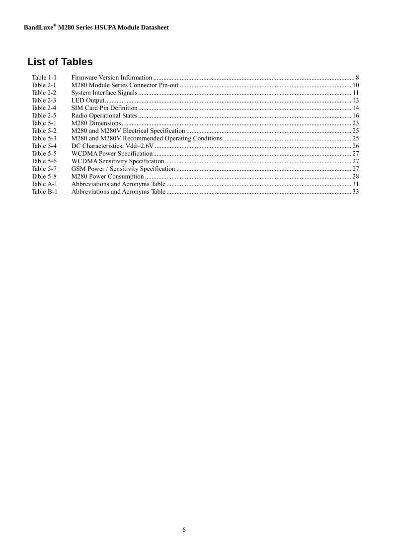
Table 2-1 M280 Module Series Connector Pin-out
Pin No. Name Pin No. Name 1 WAKE# 2 Vcc 3 N.C. 4 GND 5 N.C. 6 N.C. 7 N.C. 8 UIM_PWR 9 GND 10 UIM_DATA 11 N.C. 12 UIM_CLK 13 N.C. 14 UIM_RESET 15 GND 16 UIM_VPP(Optional)
Mechanical Key 17 N.C. 18 N.C. 19 WAKEUP#(Optional) 20 W_DISABLE# 21 GND 22 PERST# 23 N.C. 24 N.C. 25 N.C. 26 GND 27 GND 28 N.C. 29 GND 30 N.C. 31 N.C. 32 N.C. 33 N.C. 34 GND 35 GND 36 USB_D- 37 GND 38 USB_D+ 39 Vcc 40 GND 41 Vcc 42 LED_WWAN# 43 GND 44 N. C. 45 PCM_CLK (M280V only) 46 N. C. 47 PCM_DOUT (M280V only) 48 N.C. 49 PCM_DIN (M280V only) 50 GND 51 PCM_SYNC (M280V only) 52 Vcc
For more information, please refer to PCI-SIG, PCI Express Mini Card Electromechanical Specification 1.2. http://www.pcisig.com/home

BandLuxe® M280 Series HSUPA Module Datasheet
11
2.2.2 System Interface Signals
Table 2-2 summarizes the signal and power lines that are supported by the system interface.
Table 2-2 System Interface Signals
Signal Group Signal Direction Description Pin Number Vcc ( 4pins) Power source 2, 39, 41, 52
Power
GND ( 13 pins )
Return current path 4, 9, 15, 21, 26, 27, 29, 34, 35, 37, 40, 43, 50
USB USB_D+, USB_D-
Input / output
USB serial data interface compliant to the USB 2.0 specification
36, 38
Auxiliary Signals (2.6V Vdd Compliant)
PERST#
Input
Level trigger signal. Functional reset to the module
22
WAKE#
Output
Active Low, edge-trigger signal. This signal is used to request that the system return from a sleep/suspended state to service a function initiated wake event.
1
LED_WWAN#
Output Active low signals. The signal is used to allow the module to provide status indicators via LED devices that will be provided by the system.
42
Communications Specific Signals (2.6V Vdd Compliant)
W_DISABLE#
Input
Active low, level trigger signal. This signal is used by the system to disable radio operation on the module.
20
UIM_PWR (1 pin)
Output
Power source for the UIM. Compliant to the ISO/IEC 7816-3 specification (VCC).
8
UIM_RESET
Output
UIM reset signal. Compliant to the ISO/IEC 7816-3 specification (RST).
14
UIM_CLK
Output
UIM clock signal. Compliant to the ISO/IEC 7816-3 specification (CLK).
12
UIM_VPP (Not implemented in M280 series)
Output
Variable supply voltage (e.g., programming voltage) for class A devices. Refer to ISO/IEC 7816-3 for operating class definitions. This signal is reserved for future use for devices of other classes. Compliant to the ISO/IEC 7816-3 specification (VPP).
16
User Identity Module (UIM) Signals
UIM_DATA
Input / output
UIM data signal. Compliant to the ISO/IEC 7816-3 specification (I/O).
10
PCM_CLK Output PCM clock for auxiliary codec port 45

BandLuxe® M280 Series HSUPA Module Datasheet
12
Signal Group Signal Direction Description Pin Number
PCM_DOUT
Output PCM data output for auxiliary codec port
47
PCM_DIN
Input PCM data input for auxiliary codec
port
49
PCM (M280V only)
PCM_SYNC
Output PCM data strobe for auxiliary codec port
51 2.2.3 Power Source and Ground
M280 uses only 3.2V ~ +4.2V power source. For detail electrical characteristics, please refer to section 5.2.2.

BandLuxe® M280 Series HSUPA Module Datasheet
13
2.3 Network LED indicator (optional)
The Network LED indicated device is ground-referenced current sink. The host drives the device to provide a current path and an appropriate voltage for LED for M280 module. Table 2-3 describes the LED output characteristics in different states.
Table 2-3 LED Output
LED State Module Status Description LED Characteristics OFF Module is not powered. LED is OFF. ON Module is powered on.
LED is ON.

BandLuxe® M280 Series HSUPA Module Datasheet
14
2.4 USB Interface
M280 and M280V module are compliant with USB2.0 in all three modes (Low speed, Full speed, and high speed). When two devices are connected via a USB interface, one of the devices must act as a host, and the other device must act as a peripheral. The host is responsible for initiating and controlling traffic on the bus. For example, the USB specification requires PCs to act as hosts, and other devices such as M280 to act as devices.
Figure 2-3 USB Interface 2.5 USIM Interface
The universal subscriber identification module (USIM) is a smart card for UMTS/GSM cellular applications. The USIM provides the required subscription information to allow the mobile equipment to attach to a GSM or UMTS network. The USIM also provides the subscriber's verification procedures as well as authentication methods for network authentication during the network registration procedures. Upon power-up or after a soft-reset, the clock and data lines to the USIM will be active through the initialization process. Table 2-4 shows the SIM card pin definition. It’s recommended to implement hardware USIM detection mechanism or complete avoiding USIM hot-plug through mechanical design. The reference design for hardware USIM detection is provided in the “Application Note for BandLuxe Module USIM Detection Recommendation”.
Table 2-4 SIM Card Pin Definition
Pin No. Description
1 Vcc
2 RST
3 CLK
4 GND
5 Vpp
6 I/O

BandLuxe® M280 Series HSUPA Module Datasheet
15
ó USIM_CLK and USIM_RST signal, include 33pF filter capacitors is required to be placed near the SIM connector.
ó Route all USIM signals carefully – isolate them from sensitive analog and RF signals. ó External ESD diodes are necessary to protect the chip on the module; the ESD diodes should be placed
near the connector. ó Refer to the reference circuits below:
Figure 2-3 USIM Circuits Reference
VREG_USIM
0.1uF 10% 10V
33pF 5% 25V
10K 5% 1/16W
SIM Slot
USIM_P_RESET 0R
USIM_P_CLK 0R
VCC RESET CLK
GND
VPP DATA
USIM_P_DATA 0R
Varistor 3pF
3pF 40pF
40pF
2.6 Auxiliary Signals Interface
2.6.1 WAKE# (Optional)
The WAKE# signal is an open drain, active low signal that is driven low by the module to reactivate the host. The M280V module would pull WAKE# down for 250ms to send the interrupt to host when it had received a mobile terminated voice call. This auxiliary signal interface is reserved for future use for M280 module.
If the wakeup process is used, the Vcc supply must be present and used for this function. The assertion and de-assertion of WAKE# are asynchronous to any system clock. If implemented in the host platform, a host pull-up resistor (≥5 kΩ) tied to no higher than Vcc is required on this pin.
2.6.2 W_DISABLE#
Active low signal used by the system to disable radio operation on the module. The W_DISABLE# signal is provided to allow users to disable, via a system-provided switch, the module’s radio operation in order to meet public safety regulations or when otherwise desired. The W_DISABLE# signal is an active low, level trigger signal that when asserted (driven low) by the host

BandLuxe® M280 Series HSUPA Module Datasheet
16
system (Figure 2-4), the module shall disable radio operation. All transients resulting from mechanical switches need to be de-bounced by host system circuitry.
In normal operation, the module will disassociate with the wireless network and cease any further operations (transmit/receive) as soon as possible after the W_DISABLE# signal is asserted. Given that a graceful disassociation with the wireless network fails to complete in a timely manner, the module shall discontinue any communications with the network and assure that its radio operation has ceased no later than 30 seconds following the initial assertion of the W_DISABLE# signal. Once the disabling process is complete, the WWAN LED shall indicate the disabled condition to the host.
To reduce power consumption in the above mode, the module would further get into sleep (power saving) mode to turn off Baseband functionality except Real-Time-Clock circuitry and SDRAM self-refresh.
The module would initiate resuming normal operation when host de-asserts the W_DISABLE# signal.
Table 2-5 Radio Operational States
W_DISABLE# Radio Operation De-asserted Enabled (RF operation allowed) Asserted Disabled (no RF operation allowed)
The host system is required to assure that W_DISABLE# be in a deterministic state (asserted or de-asserted) whenever power is applied to the module.
Figure 2-4 System Sleep Mode On/Off Level-Trigger 2.6.3 PERST#
The PERST# signal is a level trigger signal used by the host system to force a warm rest of the module. The PERST# is normally de-asserted (high) to indicate when the system power sources are within their specified voltage tolerance and are stable. The host system can force a hardware reset on the module via asserting (driving low) PERST# signal for more than 1 second. Afterwards the host system must pull back the PERST# signal to high level and the module will continue the reset process and return to normal operation. PERST# signal will also be asserted when power is switched off.
This PERST# signal is an optional feature. The module will reset itself during the power-on process, and the host doesn’t need to reset the module.
Figure 2-5 Module Reset

BandLuxe® M280 Series HSUPA Module Datasheet
17
2.7 Antenna Guidelines and RF Connection
This section describes general guidelines for the design of multi-band antenna required for the M280 module series.
2.7.1 Antenna specifications
Frequency range ó GSM850 (824-894 MHz) ó EGSM900 (880-960 MHz) ó DCS1800 (1710-1880 MHz) ó PCS1900 (1850-1990 MHz) ó WCDMA 850/1900/2100 (824-894 / 1850-1990 / 1920-2170 MHz) Gain ó Radiation pattern: omni-directional ó Gain averaged in space in all frequencies: > -3dBm ó Gain for Diversity Antenna
1. Within 3 dB comparing to gain of primary antenna recommended 2. No worse than 6 dB of gain of primary antenna
Maximum VSWR ó < 2.5:1 with 50 reference impedance Polarization ó Linear
2.7.2 WLAN Antenna Isolation
Based upon the known isolation and the linear gain of the WLAN receiver there is a minimum requirement for the out of band isolation in the GSM and UMTS bands. The isolation is depending upon the antenna isolation, WLAN and mobile standard, the output power of the mobile, the linearity of the WLAN receiver IIP3 and the front-end filter (blocking filter). Therefore it is preferred to use WLAN modules with blocking filter.

BandLuxe® M280 Series HSUPA Module Datasheet
18
2.7.3 Antenna connector
The antenna connector type used is a U.FL microwave coaxial connector. It is also can be used for testing purpose.
Figure 2-6 Antenna Connector Position and Type
Diversity Antenna Connector
Main Antenna Connector
2.8 PCM Interface
The PCM interface can be used in two modes, and supports Linear, A-Law and μ-Law compounding algorithms: ó Auxiliary PCM that runs at 128 kHz and uses a 62.5 µs sync pulse (half a time frame). ó Primary PCM that runs at 2.048 MHz and uses 488 ns sync pulse (one 2.048 MHz clock tick).

BandLuxe® M280 Series HSUPA Module Datasheet
19
Section 3 Device Driver Interface
Basically the module will manifest itself as a composite USB device which creates stubs which the other higher level drivers hook into and provide their respective function. The composite USB device could be modem, NDIS interface, AT command interface or diagnostics interface. All device drivers used by OS have been created for Microsoft Windows 7, Vista 32/64, Windows XP SP2 above, Mac OSX, and Linux.
Either the modem or the NDIS interface can be used to transfer data; and AT command interface or diagnostic interface could be used to send/receive information of the module via the Connection Manager (CM) application. For more information about supporting AT commands please refer to section 4.

BandLuxe® M280 Series HSUPA Module Datasheet
20
This page is leave in blank for note or memo use

BandLuxe® M280 Series HSUPA Module Datasheet
21
Section 4 AT Command Set Reference
For the description of BandLuxe AT Command API, please refer to Appendix B for reference.
For the description of BandLuxe proprietary AT Command API, please refer to Appendix C for reference.
For the call related BandLuxe proprietary AT Command API, please refer to Appendix D for the description.

BandLuxe® M280 Series HSUPA Module Datasheet
22
This page is leave in blank for note or memo use

BandLuxe® M280 Series HSUPA Module Datasheet
23
Section 5 Physical Characteristics 5.1 Dimensions
Table 5-1 M280 Dimensions
Length 26.8 mm Width 30 mm Thickness 4.25 mm
Dimensions
Weight Approx 10 g Figure 5-1 M280 Dimensioned View

BandLuxe® M280 Series HSUPA Module Datasheet
24

BandLuxe® M280 Series HSUPA Module Datasheet
25
5.2 DC Electrical Specification
5.2.1 Absolute Maximum Ratings
Operating M280 module under conditions that exceed those listed in Table 5-3 result in damage to the device. Absolute maximum ratings are limiting values, and are considered individually, while all other parameters are within their specified operating ranges. Functional operation of the M280 module under any other conditions in Table 5-3 is not implied.
Table 5-2 M280 and M280V Electrical Specification
Parameter Symbol Min. Max. Units Storage temperature TS -30 +85 0C
Supply voltage Vcc -0.5 4.5 Vdc Voltage applied to any input or output pin
Vin
-0.5
Vdd + 0.5
Vdc
5.2.2 Recommended Operating Conditions
Table 5-3 M280 and M280V Recommended Operating Conditions
Parameter
Symbol
Min.
Typ.
Max.
Units Operating temperature
-10
+55 0C
Supply voltage Vcc 3.2 3.8 4.2 Vdc

BandLuxe® M280 Series HSUPA Module Datasheet
26
5.2.3 DC Characteristics
Table 5-4 DC Characteristics, Vdd=2.6V
Parameter Symbol Min. Max. Units High-level input voltage, CMOS/Schmitt
V_IH
0.65xVdd
Vdd+0.3
Volts
Low-level input voltage, CMOS/Schmitt
V_IL
-0.3
0.35xVdd
Volts
Schmitt hysteresis voltage V_SHYS 150 mV Input high leakage current I_IH — 1 uA Input low leakage current I_IL -1 — uA Input high leakage current with pull-down
I_IHPD
10
60
uA
Input low leakage current with pull-up
I_ILPU
-60
-10
uA
High-level, three-state leakage current
I_OZH
—
1
uA
Low-level, three-state leakage current
I_OZL
-1
—
uA
High-level, three-state leakage current with pull-down
I_OZHPD
10
60
uA
Low-level, three-state leakage current with pull-up
I_OZLPU
-60
-10
uA
High-level, three-state leakage current with keeper
I_OZHKP
-25
-5
uA
Low-level, three-state leakage current with keeper
I_OZLKP
5
25
uA
High-level output voltage, CMOS
V_OH
Vdd-0.45
Vdd
Volts
Low-level output voltage, CMOS
V_OL
0.0
0.45
Volts
High-voltage tolerant input leakage with a keeper
I_IHVKP
-1
1
uA
Input capacitance C_IN — 7 pF

BandLuxe® M280 Series HSUPA Module Datasheet
27
5.3 RF System Specification
The RF performance is compliant with 3GPP Mobile Station Minimum Performance specifications. Please refer to those documents for detailed specifications and test methods. The typical values of maximum transmit power and receiver sensitivity at different modes is listed below.
5.3.1 WCDMA Power
Table 5-5 WCDMA Power Specification
Tolerance Modulation
Mode
Power Class
Max Power
Normal Extreme BANDI 3 24 dBm +1/-3 dB +1.7/-3.7 dB BAND II 3 24 dBm +1/-3 dB +1.7/-3.7 dB
WCDMA BAND V 3 24 dBm +1/-3 dB +1.7/-3.7 dB
5.3.2 WCDMA Sensitivity
Table 5-6 WCDMA Sensitivity Specification
Modulation Mode <REF IOR> BANDI -106.7 dBm BAND II -104.7 dBm
CDMA BAND V -104.7 dBm
5.3.3 GSM Power/Sensitivity
Table 5-7 GSM Power / Sensitivity Specification
Tolerance Modulation
Mode
Power Class
Max Power
Normal Extreme GSM850/900 4 33 dBm ±2 dB ±2.5 dB
GMSK DCS/PCS 1 30 dBm ±2 dB ±2.5 dB GSM850/900 E2 27 dBm ±3 dB ±4 dB
EDGE DCS/PCS E2 26 dBm +3/-4 dB +4/-4.5 dB
Modulation Frequency Band Sensitivity
850 -104 dBm 900 -104 dBm 1800 -102 dBm
GMSK
1900 -102 dBm

BandLuxe® M280 Series HSUPA Module Datasheet
28
5.3.4 Power Consumption
Table 5-8 M280 Power Consumption
Test Condition M280 (Average)
Flying Mode 80 mA Flying Mode with suspend power saving 3.4 mA Sleep Mode 1.5 mA Idle Mode 84 mA Idle Mode with suspend power saving (USB ON) 13 mA HSDPA 7.2Mbps/384Kbp (Max. RF output power) 600 mA HSUPA 3.6Mbps/2Mbps (Max. RF output power) 585 mA WCDMA (Max. RF output power) 580 mA WCDMA ( 0dBm RF output power) 205 mA GPRS/EDGE 4DL/1UL (13dBm RF output power) 165 mA
5.4 Thermal Dissipation
When the module performs continuous voice call or continuously sending/receiving data packets, the surface temperature of the module shielding case at different ambient air temperature are listed below:
T≦80°C ± 5°C on surface (ambient air temperature at 55°C) T≦60°C ± 5°C on surface (ambient air temperature at 25°C)
Test Configuration Temperature: 25/55 °C Humidity: 90% humidity Duration Time: 4 hrs per condition. Test Mode: Operation mode

BandLuxe® M280 Series HSUPA Module Datasheet
29
Section 6 Packing Information
For the information about packing of shipment, packing material, and storage environment recommendation, please refers to “BandLuxe Module Packing and Storage Recommendation”.

BandLuxe® M280 Series HSUPA Module Datasheet
30
This page is leave in blank for note or memo use

BandLuxe® M280 Series HSUPA Module Datasheet
31
Appendix A Abbreviations and Acronyms
The abbreviations and acronyms used in this document.
Table A-1 Abbreviations and Acronyms Table
Abbreviations Full Name ACM Accumulated Call Meter ASCII American Standard Code for Information Interchange AT Attention commands CB Cell Broadcast CBS Cell Broadcasting Service CCM Call Control Meter CLIP Calling Line Identification Presentation CLIR Calling Line Identification Restriction CMOS Complementary Metal-Oxide Semiconductor CR Carriage Return CSD Circuit Switched Data CTS Clear To Send DAI Digital Audio Interface DCD Data Carrier Detected DCE Data Communications Equipment DRX Data Receive DSR Data Set Ready DTA Data Terminal Adaptor DTE Data Terminal Equipment DTMF Dual Tone Multi Frequency DTR Data Terminal Ready EMC Electromagnetic Compatibility ETSI European Telecommunications Equipment Institute FTA Full Type Approval (ETSI) GPRS General Radio Packet Service GPS Global Positioning System GSM Global System for Mobile communication HF Hands Free HSDPA High Speed Downlink Packet Access IMEI International Mobile Equipment Identity IMSI International Mobile Subscriber Identity IRA International Reference Alphabet ITU International Telecommunications Union IWF Inter-Working Function LCD Liquid Crystal Display LED Light Emitting Diode LF Linefeed ME Mobile Equipment MMI Man Machine Interface MO Mobile Originated MS Mobile Station

BandLuxe® M280 Series HSUPA Module Datasheet
32
Abbreviations Full Name MT Mobile Terminated OEM Other Equipment Manufacturer PB Phone Book PDU Protocol Data Unit PH Packet Handler PIN Personal Identity Number PLMN Public Land Mobile Network PUCT Price per Unit Currency Table PUK PIN Unblocking Code RACH Random Access Channel RLP Radio Link Protocol RMS Root Mean Square RTS Ready To Send RI Ring Indicator SCA Service Center Address SIM Subscriber Identity Module SMD Surface Mounted Device SMS Short Message Service SMSC Short Message Service Center SS Supplementary Service TIA Telecommunications Industry Association UDUB User Determined User Busy UMTS Universal Mobile Telecommunications System USB Universal Serial Bus USSD Unstructured Supplementary Service Data WCDMA Wideband Code Division Multiple Access 3gpp 3rd Generation Partnership Project

BandLuxe® M280 Series HSUPA Module Datasheet
33
Appendix B BandLuxe AT Command API
Appendix B lists the standard AT command that are implemented in BandLuxe M280 module series. For detail command usage and possible response, please check 3GPP TS 27.007, AT command set for User Equipment (UE).
Table B-1 Abbreviations and Acronyms Table
BandLuxe HSPA Modem AT Command Interface API Serial Port Name: BandLuxe AT CMD Interface
AT Command Command description Command Format AT&F Set all current parameters to manufacturer defaults AT&F[<mode>] AT&V Display current configuration AT&V[<mode>] ATE Enable command echo ATE ATI Display product identification information ATI ATQ Set result code presentation mode ATQ[<value>] ATV Set result code format mode ATV[<value>] ATZ Set all current parameters to user defined profile ATZ[<mode>] ATS3 Write command line termination character S3=<n>
S3? S3=?
ATS4 Set response formatting character S4=<n> S4? S4=?
ATS5 Write command line editing character S5=<n> S5? S5=?
AT+GMI Request manufacturer identification AT+GMI AT+GMM Request model identification AT+GMM AT+GMR Request revision identification of software status AT+GMR AT+GSN Request serial number identification AT+GSN AT+GCAP Request complete TA capabilities list AT+GCAP
AT+GCAP? AT+CBST Select bearer service type AT+CBST=[<speed>[, <name>[, <ce>]]]
AT+CBST? AT+CBST=?
AT+CRLP Select radio link protocol param AT+CRLP=[<iws>[, <mws>[, <T1>[, <N2>]]]] AT+CRLP? AT+CRLP=?
AT+CREG Network registration AT+CREG=[<n>] AT+CREG? AT+CREG=?
AT+CGREG GPRS network registration status AT+CGREG=[<n>] AT+CGREG? AT+CGREG=?

BandLuxe® M280 Series HSUPA Module Datasheet
34
AT Command Command description Command Format AT+CFUN Full functionality mode AT+CFUN=<mode>[,<rst>]
AT+CFUN? AT+CFUN=?
AT+GCAP Request complete TA capabilities list
AT+GCAP AT+GCAP=?
AT+CSCS Used Character Set AT+CSCS=[<chset>] AT+CSCS? AT+CSCS=?
AT+CEER Cause Location ID for the extendederror report
AT+CEER
AT+CMEE Report Mobile Terminal Error AT+CMEE=[<n>] AT+CMEE? AT+CMEE=?
AT+CGDCONT Define PDP Context AT+CGDCONT=[<cid> [,<PDP_type> [,<APN> [,<PDP_addr> [,<d_comp> ,<h_comp>]]]]]]
AT+CGDCONT? AT+CGDCONT=?
AT+CGDSCONT Define Secondary PDP Context AT+CGDSCONT=[<cid>,<p_cid>[,<d_comp>[,<h_comp>]]] AT+CGDSCONT? AT+CGDSCONT=?
AT+CGTFT Traffic Flow Template AT+CGTFT=[<cid>, [<packet filter identifier>, <evaluation precedence index> [,<source address and subnet mask> [,<protocol number (ipv4) / next header (ipv6)> [,<destination port range> [,<source port range> [,<ipsec security parameter index (spi)> [,<type of service (tos) (ipv4) and mask / traffic class (ipv6) and mask> [,<flow label (ipv6)> ]]]]]]]]]
AT+CGTFT? AT+CGTFT=?
AT+CGEQREQ 3G Quality of Service Profile (Requested)
AT+CGEQREQ=[<cid> [,<Traffic class> [,<Maximum bitrate UL> [,<Maximum bitrate DL> [,<Guaranteed bitrate UL> [,<Guaranteed bitrate DL> [,<Delivery order> [,<Maximum SDU size> [,<SDU error ratio> [,<Residual bit error ratio> [,<Delivery of erroneous SDUs> [,<Transfer delay> [,<Traffic handling priority> [,<Source statistics descriptor> [,<Signalling indication>]]]]]]]]]]]]]]]
AT+CGEQREQ? AT+CGEQREQ=?
BandLuxe® M280 Series HSUPA Module Datasheet
35
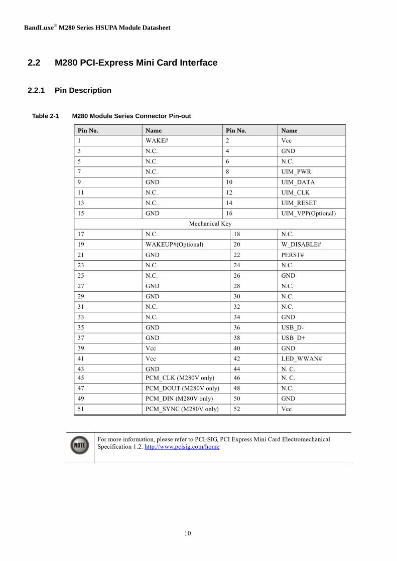
AT Command Command description Command Format AT+CGEQMIN 3G Quality of Service Profile
(Minimum acceptable) AT+CGEQMIN=[<cid> [,<Traffic class>
[,<Maximum bitrate UL> [,<Maximum bitrate DL> [,<Guaranteed bitrate UL> [,<Guaranteed bitrate DL> [,<Delivery order> [,<Maximum SDU size> [,<SDU error ratio> [,<Residual bit error ratio> [,<Delivery of erroneous SDUs> [,<Transfer delay> [,<Traffic handling priority> [,<Source statistics descriptor> [,<Signalling indication>]]]]]]]]]]]]]]]
AT+CGEQMIN? AT+CGEQMIN=?
AT+CGQREQ Quality of Service Profile (Requested)
AT+CGQREQ=[<cid>[,<precedence>[,<delay>[,<reliability.> [,<peak>[,<mean>]]]]]]
AT+CGQREQ? AT+CGQREQ=?
AT+CGQMIN Quality of Service Profile (Minimumacceptable)
AT+CGQMIN=[<cid>[,<precedence>[,<delay>[,<reliability.> [,<peak>[,<mean>]]]]]]
AT+CGQMIN? AT+CGQMIN=?
AT+CGEREP Subscriber number AT+CGEREP=[<mode>[,<bfr>]] AT+CGEREP? AT+CGEREP=?
AT+CGPADDR Show PDP address AT+CGPADDR=[<cid> [,<cid> [,…]]] AT+CGPADDR=?
AT+CGCLASS GPRS mobile station class AT+CGCLASS= [<class>] AT+CGCLASS? AT+CGCLASS=?
AT+CGSMS Select service for MO SMS messages
AT+CGSMS=[<service>] AT+CGSMS? AT+CGSMS=?
AT+CSMS Select Message Service AT+CSMS=<service> AT+CSMS? AT+CSMS=?
AT+CMGF Select SMS message format AT+CMGF=[<mode>] AT+CMGF? AT+CMGF=?
AT+CSCA Service Centrer Address AT+CSCA=<sca>[,<tosca>] AT+CSCA? AT+CSCA=?
AT+CSMP Set SMS text mode parameters AT+CSDH Show SMS text mode parameters AT+CSDH=[<show>]
AT+CSDH? AT+CSDH=?

BandLuxe® M280 Series HSUPA Module Datasheet
36
AT Command Command description Command Format AT+CSQ Request signal strength AT+CSQ
AT+CSQ=? AT+CPIN Check PIN Status AT+CPIN=<pin>[,<newpin>]
AT+CPIN? AT+CPIN=?
AT+CGATT PS attach / detach AT+CGATT= [<state>] AT+CGATT? AT+CGATT=?
AT+CGACT PDP context activate or deactivate AT+CGACT=[<state> [,<cid>[,<cid>[,…]]]] AT+CGACT? AT+CGACT=?
AT+CGCMOD PDP Context Modify AT+CGCMOD=[<cid>[,<cid>[,…]]] AT+CGCMOD=?
AT+CPBS Select phone book memory storage AT+CPBS=<storage> AT+CPBS? AT+CPBS=?
AT+CPBR Read Phonebook Memory entries AT+CPBR=<index1>[,<index2>] AT+CPBR?
AT+CPBF Find Phonebook Memory entries AT+CPBF=<findtext> AT+CPBF=?
AT+CPBW Write phone book entry AT+CPBW=[<index>][,<number>[,<type>[,<text>]]] AT+CPBW=?
AT+CPMS Preferred Message Storage AT+CPMS=<mem1>[, <mem2>[,<mem3>]] AT+CPMS? AT+CPMS=?
AT+CNMI New Message Indications to TE AT+CNMI=[<mode>[,<mt>[,<bm>[,<ds>[,<bfr>]]]]] AT+CNMI? AT+CNMI=?
AT+CMGL List Messages AT+CMGL[=<stat>] AT+CMGL=?
AT+CMGR Read Message AT+CMGR=<index> AT+CMGR=?
AT+CMGS Send SMS message AT+CMGS=<da>[,<toda>] AT+CMGS=?
AT+CMGD Delete SMS message AT+CMGD=<index> AT+CMGD=?
AT+CNMA New SMS message acknowledge to ME/TE
AT+CNMA AT+CNMA=?
AT+COPS Operator selection AT+COPS[=<mode>[, <format>[, <oper>]]] AT+COPS? AT+COPS=?
AT+CLCK Facility lock AT+CLCK=<fac>,<mode>[,<passwd>[,<class>]] AT+CLCK=?

BandLuxe® M280 Series HSUPA Module Datasheet
37
AT Command Command description Command Format
AT+CPWD Change password AT+CPWD=<fac>,<oldpwd>,<newpwd> AT+CPWD=?
AT+CUSD Unstructured supplementary service data
AT+CUSD=[<n>[,<str>[,<dcs>]]] AT+CUSD? AT+CUSD=?
AT+CIMI Read IMSI AT+CIMI AT+CIMI=?
AT+CGMI Request manufacturer identification AT+CGMI AT+CGMM Request model identification AT+CGMM AT+CGMR Request revision identification AT+CGMR AT+CGSN Request product serial number
identification AT+CGSN
AT+CNUM Subscriber number AT+CNUM AT+CNUM=?
AT+CSIM Generic SIM access +COLP=[<n>] AT+CRSM Restricted SIM access AT+CRSM=<command>[,<fileid>[,<P1>,<P2>,<P3>[,<data>]]]
AT+CRSM=?
AT+COPN Read operator names AT+COPN AT+COPN=?
AT+CPOL Preferred PLMN list AT+CPOL=[<index>][,<format>[,<oper>]] AT+CPOL? AT+CPOL=?
AT+CPLS Selection of preferred PLMN list AT+CPLS=<list> AT+CPLS? AT+CPLS=?
AT+CTZR Time Zone Reporting AT+CTZR=<onoff> AT+CTZR? AT+CTZR=?
AT+CPINC The retries count of PIN1, PIN2, PUK1 or PUK2
AT+CPINC AT+CPINC=?

BandLuxe® M280 Series HSUPA Module Datasheet
38
Appendix C BandLuxe Proprietary AT Command API
Appendix C lists the BandLuxe proprietary AT command that are implemented in BandLuxe M280 module series.
C.1 AT$SYSMODE – Query current network type
C.1.1 DESCRIPTION
Query current network type
C.1.2 SYNTAX
Command Possible response(s)
$SYSMODE=<format> OK $SYSMODE[ ?] $SYSMODE: <mode>
OK $SYSMODE=? $SYSMODE: (0-1)
OK C.1.3 PARAMETERS
<format> [0] alphanumeric <mode> 1 numeric <mode>
<mode>
Numeric Mode Alphanumeric Mode 0 NO SERVICE 1 GSM 2 GPRS 3 EDGE 4 WCDMA 5 HSDPA
C.1.4 Examples
test command example: AT$SYSMODE=? $SYSMODE: (0-1) OK
query command example: AT$SYSMODE? $SYSMODE: NO SERVICE OK
set command example: AT$SYSMODE =1 OK

BandLuxe® M280 Series HSUPA Module Datasheet
39
C.2 AT$PREFNETTYPE – Set Prefer network type
C.2.1 DESCRIPTION
Set prefer network type
C.2.2 SYNTAX
Command Possible response(s)
$PREFNETTYPE=<mode> OK $PREFNETTYPE? $PREFNETTYPE: <mode>
OK $PREFNETTYPE=? $PREFNETTYPE: (0-4)
OK C.2.3 PARAMETERS
<mode>
0 WCDMA only 1 WCDMA first 2 Automatic 3 GSM first 4 GSM only
C.2.4 Examples
test command example: AT$PREFNETTYPE=? $PREFNETTYPE: (0-4)
OK
query command example: AT$PREFNETTYPE? $PREFNETTYPE: 1
OK
set command example: AT$ PREFNETTYPE =1 OK
BandLuxe® M280 Series HSUPA Module Datasheet
40
Appendix D Call Related Standard AT Command API and BandLuxe Proprietary AT Command API
This Appendix list call related BandLuxe proprietary AT commands and examples of some call related standard AT commands implemented in M280V module. BandLuxe M280V module also provides unsolicited information of the call states for call management.
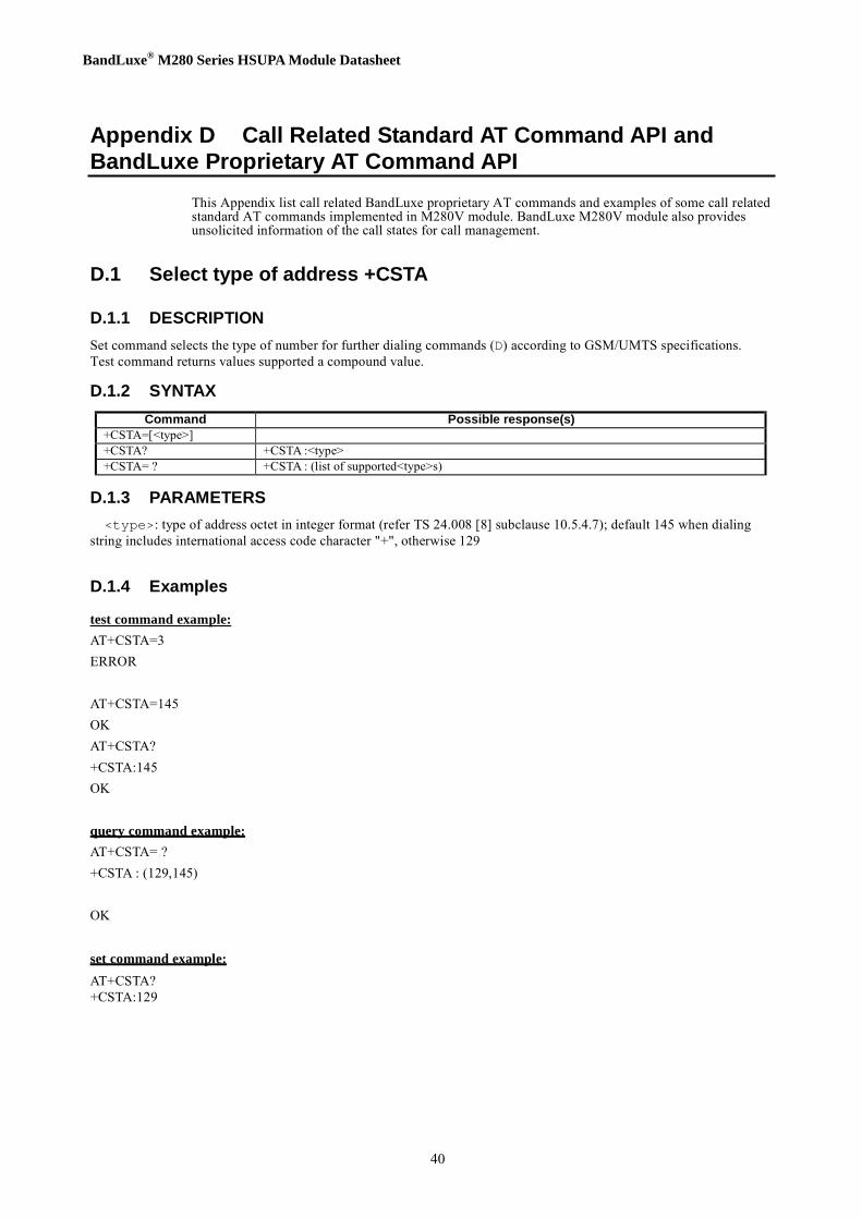
D.1 Select type of address +CSTA
D.1.1 DESCRIPTION
Set command selects the type of number for further dialing commands (D) according to GSM/UMTS specifications. Test command returns values supported a compound value.
D.1.2 SYNTAX
Command Possible response(s)
+CSTA=[<type>] +CSTA? +CSTA :<type> +CSTA= ? +CSTA : (list of supported<type>s)
D.1.3 PARAMETERS
<type>: type of address octet in integer format (refer TS 24.008 [8] subclause 10.5.4.7); default 145 when dialing string includes international access code character "+", otherwise 129
D.1.4 Examples
test command example: AT+CSTA=3 ERROR
AT+CSTA=145 OK AT+CSTA? +CSTA:145 OK
query command example: AT+CSTA= ? +CSTA : (129,145)
OK
set command example: AT+CSTA? +CSTA:129

BandLuxe® M280 Series HSUPA Module Datasheet
41
D.2 Originate a call : ATD<dialstring> ;
D.2.1 DESCRIPTION
Originate a call
D.2.2 SYNTAX
Command Possible response(s)
D<dialstring> ; OK ERROR NO CARRIOR
D.2.3 PARAMETERS
<dialstring>
Dailing string D.2.4 Examples
test command example: ATD123; OK
D.3 Answer a call : ATA
D.3.1 DESCRIPTION
Answer a call
D.3.2 SYNTAX
Command Possible response(s)
A OK ERROR
D.3.3 PARAMETERS
NONE
D.3.4 Examples
test command example: ATA OK
BandLuxe® M280 Series HSUPA Module Datasheet
42
D.4 Call Mode +CMOD
D.4.1 DESCRIPTION
Set command selects the call mode of further dialing commands (D) or for next answering command (A). Mode can be either single or alternating (in the present document, terms "alternating mode" and "alternating call" refer to all GSM/UMTS bearer and teleservices that incorporate more than one basic service (voice, data, fax) within one call). When single mode is selected the call originating and hang-up procedures are similar to procedures specified in ITU-T Recommendations V.25ter [14], T.31 [11] and T.32 [12]. In GSM/UMTS there can be voice followed by data (refer 3GPP TS 22.002 [1]), alternating voice/data (refer 3GPP TS 22.002 [1]) and alternating voice/fax calls (refer 3GPP TS 22.003 [2]). Refer next two subclauses for alternating call control methods. Test command returns values supported as a compound value. NOTE: +CMOD shall be set to zero after a successfully completed alternating mode call. It shall be set to zero also after a failed answering. The power-up, factory (&F) and user resets (Z) shall also set the value to zero. This reduces the possibility that alternating mode calls are originated or answered accidentally.
D.4.2 SYNTAX
Command Possible response(s)
+CMOD=[<mode>] +CMOD? +CMOD :<mode> +CMOD= ? +CMOD: (list of supported<mode>s)
D.4.3 PARAMETERS
<mode>: 0 single mode 1 alternating voice/fax (teleservice 61) 2 alternating voice/data (bearer service 61) 3 voice followed by data (bearer service 81) also all other values below 128 are reserved by the present document
D.4.4 Examples
test command example: AT+CMOD=1 OK
query command example: AT+CMOD= ? +CMOD : (0) OK
set command example: AT+CMOD? +CMOD:0
OK

BandLuxe® M280 Series HSUPA Module Datasheet
43
D.5 Hangup call : AT+CHUP
D.5.1 DESCRIPTION
Execution command causes the TA to hang up the current GSM/UMTS call of the MT.
D.5.2 SYNTAX
Command Possible response(s)
+CHUP +CHUP= ?
D.5.3 PARAMETERS
NONE
D.5.4 Examples
test command example: AT+CHUP OK
query command example: AT+CHUP= ? OK
D.6 Cellular Result Code +CRC
D.6.1 DESCRIPTION
Set command controls whether or not the extended format of incoming call indication or GPRS network request for PDP context activation or notification for VBS/VGCS calls is used. When enabled, an incoming call is indicated to the TE with unsolicited result code +CRING: <type> instead of the normal RING.
Test command returns values supported as a compound value. ETSI 3GPP TS 27.007 version 5.4.0 Release 5 33 ETSI TS 127 007 V5.4.0 (2003-09) NOTE: Similar command may be found in TIA IS-99 [15] and TIA IS-135 [16].
D.6.2 SYNTAX
Command Possible response(s)
+CRC=[<mode>] +CRC ? +CRC : <mode> +CRC= ? +CRC : (list of supported<mode>s)
D.6.3 PARAMETERS
<mode>: 0 disables extended format 1 enables extended format <type>: ASYNC [,<priority>[,<subaddr>,<satype>]] asynchronous transparent

BandLuxe® M280 Series HSUPA Module Datasheet
44
SYNC [,<priority>[,<subaddr>,<satype>]] synchronous transparent REL ASYNC [,<priority>[,<subaddr>,<satype>]] asynchronous non-transparent REL SYNC [,<priority>[,<subaddr>,<satype>]] synchronous non-transparent FAX [,<priority>[,<subaddr>,<satype>]] facsimile (TS 62) VOICE [,<priority>[,<subaddr>,<satype>]] normal voice (TS 11) VOICE/XXX [,<priority>[,<subaddr>,<satype>]] voice followed by data (BS 81) (XXX is ASYNC, SYNC, REL ASYNC or REL SYNC) ALT VOICE/XXX [,<priority>[,<subaddr>,<satype>]] alternating voice/data, voice first (BS 61)
ALT XXX/VOICE [,<priority>[,<subaddr>,<satype>]] alternating voice/data, data first (BS 61) ALT VOICE/FAX [,<priority>[,<subaddr>,<satype>]] alternating voice/fax, voice first (TS 61)
ALT FAX/VOICE [,<priority>[,<subaddr>,<satype>]] alternating voice/fax, fax first (TS 61) GPRS <PDP_type>, <PDP_addr>[, [<L2P>][,<APN>]] GPRS network request for PDP context activation VGC <GCA>, <GId>, <ackflag> [,<priority>] voice group call (TS 91) VBC <GCA>, <GId>, <ackflag> [,<priority>] voice broadcast call (TS 92) The optional <priority> indicates the eMLPP priority level of the incoming call by paging, notification or setup message. The priority level values are as defined in eMLPP specification 3GPP TS 22.067 [54]. <subaddr>: string type subaddress of format specified by <satype> <satype>: type of subaddress octet in integer format (refer 3GPP TS 24.008 [8] subclause 10.5.4.8) <PDP_type> ,<PDP_addr> and <APN> are as defined in the Define PDP Context (+CGDCONT) command. The optional <L2P> proposes a layer 2 protocol to use between the MT and the TE. It is defined in the Enter GPRS Data Mode (+CGDATA) command. If the MT is unable to announce to the TE the network's request (for example it is in V.25ter online data state) the MT shall reject the request. No corresponding unsolicited result code shall be issued when the MT returns to a command state. <GCA> is a part of the group call reference as specified in 3GPP TS 23.003 [7] and indicates group call area. <GId> is a part of the group call reference as specified in 3GPP TS 23.003 [7] and indicates group call identification.The <ackflag>=1 proposes that a predefined confirmation procedure is to be used after the call is ended. For <ackflag>=0 no confirmation procedure is required.
D.6.4 Examples
test command example: AT+CRC=1 OK
query command example: AT+CRC= ? +CRC : (0,1)
OK
set command example: AT+CRC? +CRC:1
OK
D.7 DTMF control over the CS call in conversation state: AT+DTMF
D.7.1 DESCRIPTION
Execution command emulates MT keypad by giving each keystroke as a character while CS domain voice call is in

BandLuxe® M280 Series HSUPA Module Datasheet
45
conversation state.
D.7.2 SYNTAX
Command Possible response(s) +DTMF= <cid>, <key> +CME ERROR: <err> +DTMF=?
D.7.3 PARAMETERS
<cid>: integer type; call identification number as described in 3GPP TS 22.030 subclause 4.5.5.1.
<key>: DTMF digit; the representing character key is listed in the following table.
Char IRA(dec) # 35 * 42 0…9 48…57 A/a 65/97 B/b 66/98 C/c 67/99 D/d 68/100
D.7.4 Examples
query command example: AT+DTMF= ? OK set command example: AT+DTMF=1,1 OK
D.8 Call forwarding number and conditions : AT+CCFC
D.8.1 DESCRIPTION
This command allows control of the call forwarding supplementary service according to 3GPP TS 22.082. Registration, erasure, activation, deactivation, and status query are supported. When querying the status of a network service (<mode>=2) the response line for 'not active' case (<status>=0) should be returned only if service is not active for any <class>. Test command returns reason values supported as a compound value.
D.8.2 SYNTAX
Command Possible response(s)
+CCFC=<reason>,<mode> [,<number>[,<type> [,<class> [,<subaddr>[,<satype> [,<time>]]]]]]
+CME ERROR: <err> when <mode>=2 and command successful: +CCFC: <status>,<class1>[,<number>,<type> [,<subaddr>,<satype>[,<time>]]][ <CR><LF>+CCFC: <status>,<class2>[,<number>,<type> [,<subaddr>,<satype>[,<time>]]] [...]]
+CCFC=? +CCFC: (list of supported <reason>s)

BandLuxe® M280 Series HSUPA Module Datasheet
46
D.8.3 PARAMETERS
<reason>: 0 unconditional 1 mobile busy 2 no reply 3 not reachable 4 all call forwarding (refer 3GPP TS 22.030 [19]) 5 all conditional call forwarding (refer 3GPP TS 22.030 [19]) <mode>: 0 disable 1 enable 2 query status 3 registration 4 erasure <number>: string type phone number of forwarding address in format specified by <type> <type>: type of address octet in integer format (refer TS 24.008 [8] subclause 10.5.4.7); default 145 when dialling string includes international access code character "+", otherwise 129 <subaddr>: string type subaddress of format specified by <satype> <satype>: type of subaddress octet in integer format (refer TS 24.008 [8] subclause 10.5.4.8); default 128 <classx> is a sum of integers each representing a class of information (default 7): 1 voice (telephony) 2 data (refers to all bearer services; with <mode>=2 this may refer only to some bearer service if TA does not support values 16, 32, 64 and 128) 4 fax (facsimile services) 8 short message service 16 data circuit sync 32 data circuit async 64 dedicated packet access 128 dedicated PAD access <time>: 1...30 when "no reply" is enabled or queried, this gives the time in seconds to wait before call is forwarded, default value 20 <status>: 0 not active 1 active
D.8.4 Examples
test command example: AT+CCFC=2,1,”921654321” (Enable CFB) OK
AT+CCFC=1 (Query CFNRy) +CCFC: 1,7,”+35821654321”,145,,,20 (forward after 20 seconds) OK
query command example: AT+CCFC= ? +CCFC :(0,1,2,3,4,5)
OK

BandLuxe® M280 Series HSUPA Module Datasheet
47
D.9 Call waiting : AT+CCWA
D.9.1 DESCRIPTION
This command allows control of the Call Waiting supplementary service according to 3GPP TS 22.083. Activation, deactivation and status query are supported. When querying the status of a network service (<mode>=2) the response line for 'not active' case (<status>=0) should be returned only if service is not active for any <class>. Parameter <n> is used to disable/enable the presentation of an unsolicited result code +CCWA: <number>,<type>,<class>,[<alpha>][,<CLI validity>[,<subaddr>,<satype> [,<priority> ]]] to the TE when call waiting service is enabled. Command should be abortable when network is interrogated. The interaction of this command with other commands based on other GSM/UMTS supplementary services is described in the GSM/UMTS standards. Test command returns values supported as a compound value.
D.9.2 SYNTAX
Command Possible response(s)
+CCWA=[<n>[,<mode>[,< class>]]]
+CME ERROR: <err> when <mode>=2 and command successful +CCWA: <status>,<class1> [<CR><LF>+CCWA: <status>,<class2> [...]]
+CCWA? +CCWA: <n> +CCWA=? +CCWA: (list of supported <n>s)
D.9.3 PARAMETERS
<n> (sets/shows the result code presentation status to the TE):
0 disable 1 enable <mode> (when <mode> parameter is not given, network is not interrogated): 0 disable 1 enable 2 query status <classx> is a sum of integers each representing a class of information (default 7): 1 voice (telephony) 2 data (refers to all bearer services; with <mode>=2 this may refer only to some bearer service if TA does not support values 16, 32, 64 and 128) 4 fax (facsimile services) 8 short message service 16 data circuit sync 32 data circuit async 64 dedicated packet access 128 dedicated PAD access <status>: 0 not active 1 active <number>: string type phone number of calling address in format specified by <type> <type>: type of address octet in integer format (refer TS 24.008 subclause 10.5.4.7) <alpha>: optional string type alphanumeric representation of <number> corresponding to the entry found in phonebook; used character set should be the one selected with command Select TE Character Set +CSCS <CLI validity>: 0 CLI valid 1 CLI has been withheld by the originator. 2 CLI is not available due to interworking problems or limitations of originating network. When CLI is not available (<CLI validity>=2), <number> shall be an empty string ("") and <type> value will

BandLuxe® M280 Series HSUPA Module Datasheet
48
not be significant. Nevertheless, TA may return the recommended value 128 for <type> ((TON/NPI unknown in accordance with TS 24.008 subclause 10.5.4.7). When CLI has been withheld by the originator, (<CLI validity>=1) and the CLIP is provisioned with the "override category" option (refer 3GPP TS 22.081 and 3GPP TS 23.081), <number> and <type> is provided. Otherwise, TA shall return the same setting for <number> and <type> as if the CLI was not available. <subaddr>: string type subaddress of format specified by <satype> <satype>: type of subaddress octet in integer format (refer TS 24.008 subclause 10.5.4.8) <priority>: optional digit type parameter indicating that the eMLPP priority level of the incoming call. The priority level values are as defined in eMLPP specification 3GPP TS 22.067.
D.9.4 Examples
test command example: AT+CCWA=1,1
OK
query command example: AT+CCWA= ? +CCWA :(0-1)
OK
set command example: AT+CCWA? +CCWA:0
OK
D.10 Call related supplemenatry services : AT+CHLD
D.10.1 DESCRIPTION
This command allows the control of the following call related services: - a call can be temporarily disconnected from the MT but the connection is retained by the network; - multiparty conversation (conference calls); - the served subscriber who has two calls (one held and the other either active or alerting) can connect the other parties and release the served subscriber's own connection. Calls can be put on hold, recovered, released, added to conversation, and transferred similarly as defined in 3GPP TS 22.030. This is based on the GSM/UMTS supplementary services HOLD (Call Hold; refer 3GPP TS 22.083 clause 2), MPTY (MultiParty; refer 3GPP TS 22.084) and ECT (Explicit Call Transfer; refer 3GPP TS 22.091). The interaction of this command with other commands based on other GSM/UMTS supplementary services is described in the GSM/UMTS standards. NOTE: Call Hold, MultiParty and Explicit Call Transfer are only applicable to teleservice 11. It is recommended (although optional) that test command returns a list of operations which are supported. The call number required by some operations shall be denoted by "x" (e.g. +CHLD: (0,1,1x,2,2x,3)).

BandLuxe® M280 Series HSUPA Module Datasheet
49
D.10.2 SYNTAX
Command Possible response(s)
+CHLD=[<n] +CME ERROR: <err> +CHLD= ? [+CHLD: (list of supported <n>s)]
D.10.3 PARAMETERS
<n>: integer type; equals to numbers entered before SEND button in 3GPP TS 22.030 [19] subclause 4.5.5.1 NOTE: The "directory number" case shall be handled with dial command D, and the END case with hangup command H (or +CHUP). The 4*"directory number" case is handled with +CTFR command.
D.10.4 Examples
test command example: AT+CHLD=2 (put first call on hold and answer the second one) OK
AT+CHLD=1 (release the second (active) call and recover the first(held) call) OK query command example: AT+CHLD= ? +CHLD :(0,1,1x,2,2x,3,4)
OK
D.11 AT$CPI – Request current call status
D.11.1 DESCRIPTION
Standard AT command +CLCC can not meet the implementation requirement because it is not an unsolicited command. User has to poll the call status. It wastes the computing power. We offer two unsolicited commands to reflect current call status. It is easier for MMI designer to implement the dialer application.
D.11.2 SYNTAX
Command Possible response(s) $CPI=<n> $CPI=? $CPI= 0, 1 $CPI? $CPI = <n> Unsolicited call progress indication format
$CPI: <cid>, <dir>, <stat>, <mode>, <mpty>, <tch>, <number>, <type> <CR><LF>
D.11.3 PARAMETERS
<n>: 0 no unsolicited call progress indication report to TE 1 enable the unsolicited report function <cId>: integer type; call identification number as described in 3GPP TS 22.030 [19] subclause 4.5.5.1; <dir>: 0 mobile originated (MO) call 1 mobile terminated (MT) call

BandLuxe® M280 Series HSUPA Module Datasheet
50
<stat> (state of the call): 0 active 1 held 2 dialing (MO call) 3 alerting (MO call) 4 incoming (MT call) 5 waiting (MT call) 6 disconnected <mode> (bearer/teleservice): 0 voice 1 data 2 fax 3 voice followed by data, voice mode 4 alternating voice/data, voice mode 5 alternating voice/fax, voice mode 6 voice followed by data, data mode 7 alternating voice/data, data mode 8 alternating voice/fax, fax mode 9 unknown <mpty>: 0 call is not one of multiparty (conference) call parties 1 call is one of multiparty (conference) call parties <tch>: TCH assigned flag; It is used to indicate if Traffic Channel has be assigned. <number>: string type phone number in format specified by <type> <type>: type of address octet in integer format (refer TS 24.008 [8] subclause 10.5.4.7)
D.12 User Scenario
D.12.1 Originate call
atd123; (originate call to number: 123) OK $CPI:1,0,2,0,0,0,"123",129 (call in dialing state) $CPI:1,0,3,0,0,1,"123",129 (call in alerting state) $CPI:1,0,0,0,0,1,"123",129 (call in active state) AT+CHUP (Hangup call) OK $CPI:1,0,6,0,0,0,"123",129 (call in disconnected state)
D.12.2 Termination call
RING (incoming call) $CPI:1,1,4,0,0,1,"0277051073",128 (call in incoming state, call number = “0277051073”) ata (answer call) OK (respose OK) $CPI:1,1,0,0,0,1,"0277051073",128 (call in active state) at+chup (hangup call) OK $CPI:1,1,6,0,0,0,"0277051073",128 (call in disconnected state)
D.12.3 PIN Code Enable
at+clck="sc",1,"0000" OK

BandLuxe® M280 Series HSUPA Module Datasheet
51
D.12.4 Enter PIN Code
at+cpin="0000" OK
D.12.5 PIN Code Disable
at+clck="sc",0,"0000" OK


![[Job training] hsdpa+hsupa](https://img.dokumen.tips/doc/110x75/58e7b4ac1a28abbb4e8b5297/job-training-hsdpahsupa.jpg)