Embed Size (px)
Citation preview
2015.07.16.
1
MTA SZTAKI, Distributed Events Analysis Research Laboratory
http://web.eee.sztaki.hu/i4d/
Csaba Benedek Zsolt Jankó
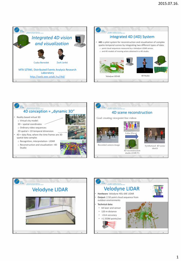
Integrated 4D vision and visualization
integrated 4D (i4D) System • i4D: a pilot system for reconstruction and visualisation of complex
spatio-temporal scenes by integrating two different types of data: o point cloud sequences measured by a Velodyne LIDAR sensor,
o and 4D models of moving actors obtained in a 4D studio.
4D Studio Velodyne LIDAR
4D conception = „dynamic 3D”
• Reality based virtual 3D
o Virtual city model:
3D – spatial coordinates
o Ordinary video sequences:
2D spatial + 1D temporal dimension
• 4D = data flow, where the time frames are 3D spatial data samples
o Recognition, interpretation– LIDAR
o Reconstruction and visualization– 4D Studio
Synthetized 4D scene sketch
Goal: creating viewpoint free videos
Lidar (Deva)
4D reconstruction studio (GMCV)
4D scene reconstruction
Recorded camera image
Velodyne LIDAR Velodyne LIDAR • Hardware: Velodyne HDL-64E LIDAR
• Output: 2.5D point cloud sequence from outdoor environments
• Technical data:
• 64 laser and sensor
• 120 m distance
• <2cm accuracy
• >1.333M points/sec
2015.07.16.
2
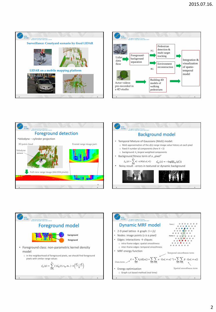
Surveillance: Courtyard scenario by fixed LIDAR
LIDAR on a mobile mapping platform
Foreground-
background
separation
Pedestrian
detection &
multi target
tracking Lidar data flow Environment
reconstruction
Integration &
visualization
of spatio-
temporal
model
Building 4D
models of
walking
pedestrians
Actor videos pre-recorded in a 4D studio
BG
FG
Foreground detection •Velodyne – cylinder projection
9
Frontal range image part:
Full view range image (64x1024 pixels):
Velodyne sensor
3D point cloud
Background model
• Temporal Mixture of Gaussians (MoG) model:
o MoG approximation of the d(s) range image value history at each pixel
o fixed K number of components (here K = 5)
o background: ks largest weighted components
• Background fitness term of a „pixel”
• Noisy result - errors in textured or dynamic background
𝑓𝑏𝑔 𝑝 = 𝑤𝑠𝑖 ∙ 𝜂
𝑘𝑠
𝑖=1
(d p ,μsi ,σs
i ) 𝜀𝑏𝑔𝑡 𝑠 = −log(𝑓𝑏𝑔 𝑝𝑠
𝑡 )
Foreground model
• Foreground class: non-parametric kernel density model o in the neighborhood of foreground pixels, we should find foreground
pixels with similar range values
𝜀𝑓𝑔𝑡 𝑝 = 𝜁
𝑘𝑠
𝑟∈𝑁𝑠
(εbgt r , τfg ,m∗ ) ∙ 𝑘
𝑑𝑠𝑡 − 𝑑𝑟
𝑡
ℎ
𝐸 = 𝑉𝐷 dst ωs
t + 𝛼 ∙ 1 ωst ≠ ωr
t−1 +
𝑟∈𝑁𝑠
𝛽 ∙ 1 ωst ≠ ωr
t
𝑟∈𝑁𝑠𝑠∈𝑆𝑠∈𝑆𝑠∈𝑆
Dynamic MRF model • 2-D pixel lattice → graph: S = {s}
• Nodes: image points (s is a pixel)
• Edges: interactions → cliques o intra-frame edges: spatial smoothness
o inter-frame edges: temporal smoothness
• MRF energy function
• Energy optimization o Graph cut based method (real time)
Spatial smoothness term
Temporal smoothness term
Data term
2015.07.16.
3
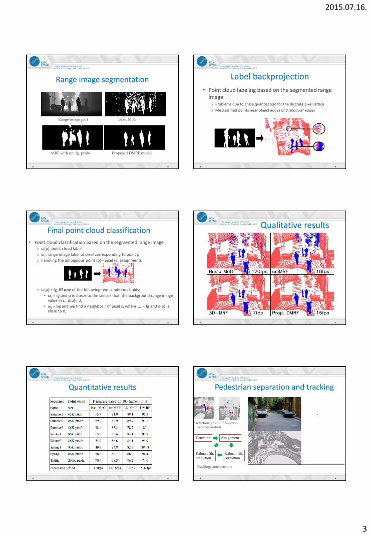
Range image segmentation
Range image part Basic MoG
MRF with uni fg. probs Proposed DMRF model
Label backprojection
• Point cloud labeling based on the segmented range image o Problems due to angle quantization for the discrete pixel lattice
o Misclassified points near object edges and,‘shadow’ edges
Final point cloud classification
• Point cloud classification based on the segmented range image o ω(p): point cloud label
o ωs: range image label of pixel corresponding to point p
o handling the ambiguous point (p) - pixel (s) assignments
o ω(p) = fg, iff one of the following two conditions holds:
• ωs = fg and p is closer to the sensor than the background range image value in s: d(p)< ds
• ωs = bg and we find a neighbor r of pixel s, where ωr = fg and d(p) is close to dr
Qualitative results
Quantitative results Pedestrian separation and tracking
Tracking: state machine
Detection: ground projection + blob separation
Detection Assignment
Kalman filt.
correction
Kalman filt.
prediction
2015.07.16.
4
2D panorama photo
3D surface model 3D textured scene model
2.5D point cloud
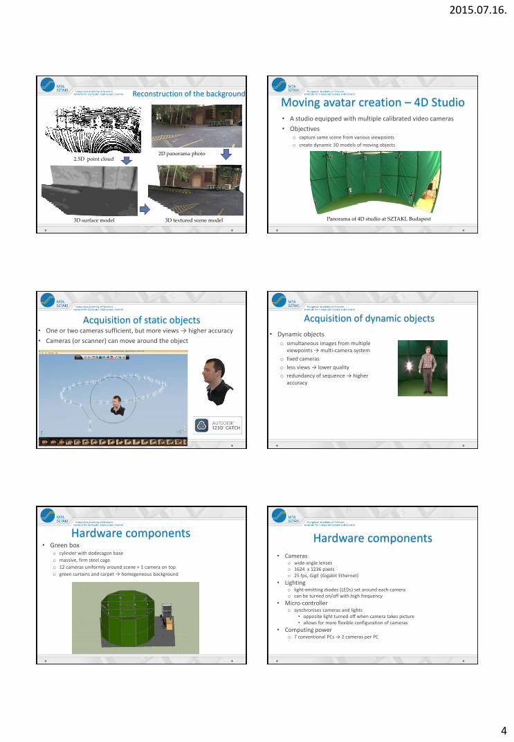
Reconstruction of the background Moving avatar creation – 4D Studio • A studio equipped with multiple calibrated video cameras
• Objectives o capture same scene from various viewpoints
o create dynamic 3D models of moving objects
Panorama of 4D studio at SZTAKI, Budapest
Acquisition of static objects • One or two cameras sufficient, but more views → higher accuracy
• Cameras (or scanner) can move around the object
Acquisition of dynamic objects
• Dynamic objects
o simultaneous images from multiple viewpoints → multi-camera system
o fixed cameras
o less views → lower quality
o redundancy of sequence → higher accuracy
Hardware components • Green box
o cylinder with dodecagon base
o massive, firm steel cage
o 12 cameras uniformly around scene + 1 camera on top
o green curtains and carpet → homogeneous background
Hardware components • Cameras
o wide-angle lenses o 1624 x 1236 pixels o 25 fps, GigE (Gigabit Ethernet)
• Lighting o light-emitting diodes (LEDs) set around each camera o can be turned on/off with high frequency
• Micro-controller o synchronises cameras and lights
• opposite light turned off when camera takes picture • allows for more flexible configuration of cameras
• Computing power o 7 conventional PCs → 2 cameras per PC
2015.07.16.
5
Hardware components
Adjustable platform with video camera and LEDs mounted on cage
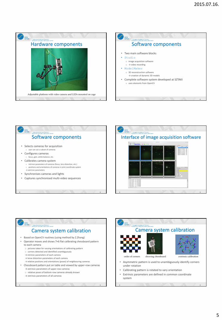
Software components
• Two main software blocks
• Studio
o image acquisition software
o → video recording
• ModelMaker
o 3D reconstruction software
→ creation of dynamic 3D models
• Complete software system developed at SZTAKI o uses elements from OpenCV
Software components
• Selects cameras for acquisition o user can use a subset of cameras
• Configures cameras o focus, gain, white balance, etc.
• Calibrates camera system o intrinsic parameters of cameras (focus, lens distortion, etc.)
o positions and orientations of cameras in joint coordinate system
→ extrinsic parameters
• Synchronises cameras and lights
• Captures synchronised multi-video sequences
Interface of image acquisition software
Camera system calibration • Based on OpenCV routines (using method by Z.Zhang)
• Operator moves and shows 7×6 flat calibrating chessboard pattern to each camera o pictures taken for varying orientations of calibrating pattern
o corners detected and identified unambiguously
→ intrinsic parameters of each camera
→ lense distortion parameters of each camera
→ relative positions and orientations (poses) of neighbouring cameras
• Chessboard pattern put on table and viewed by upper-row cameras
→ extrinsic parameters of upper-row cameras
o relative poses of bottom-row cameras already known
→ extrinsic parameters of all cameras
Camera system calibration
• Asymmetric pattern is used to unambiguously identify corners under rotation
• Calibrating pattern is rotated to vary orientation
• Extrinsic parameters are defined in common coordinate system
showing chessboard extrinsic calibration order of corners
2015.07.16.
6
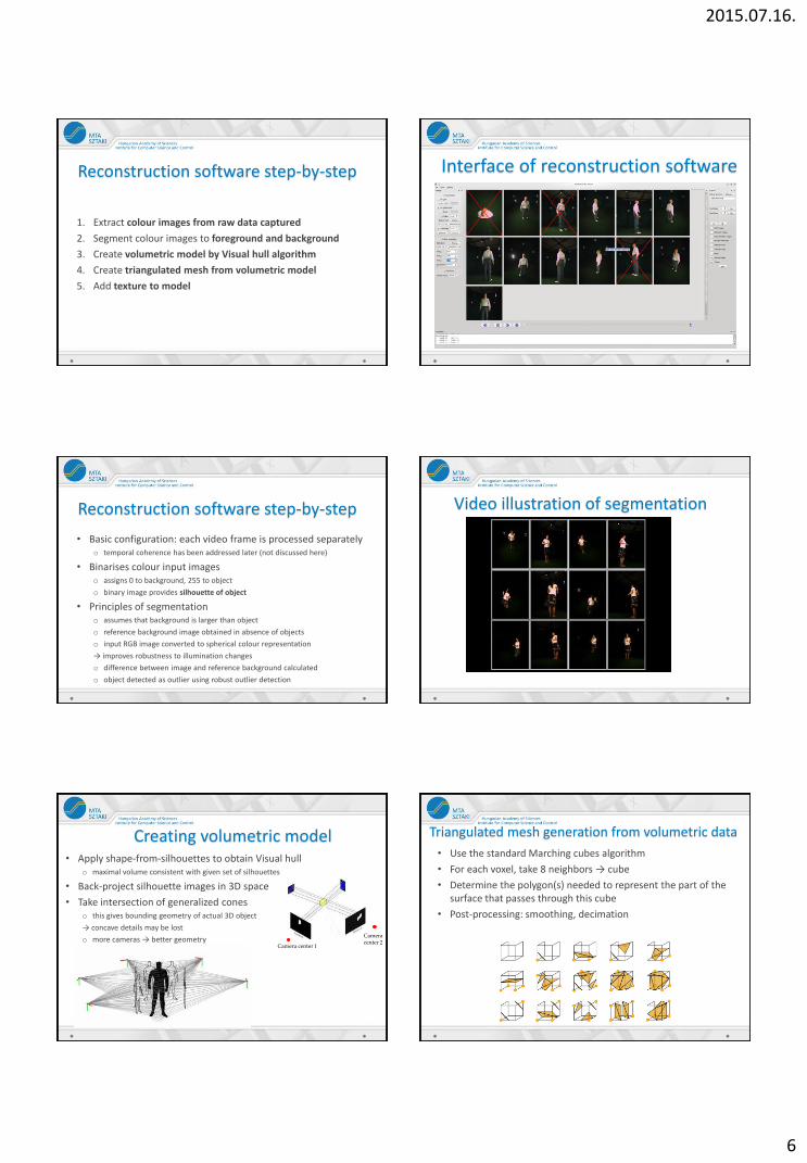
Reconstruction software step-by-step
1. Extract colour images from raw data captured
2. Segment colour images to foreground and background
3. Create volumetric model by Visual hull algorithm
4. Create triangulated mesh from volumetric model
5. Add texture to model
Interface of reconstruction software
Reconstruction software step-by-step
• Basic configuration: each video frame is processed separately o temporal coherence has been addressed later (not discussed here)
• Binarises colour input images o assigns 0 to background, 255 to object
o binary image provides silhouette of object
• Principles of segmentation o assumes that background is larger than object
o reference background image obtained in absence of objects
o input RGB image converted to spherical colour representation
→ improves robustness to illumination changes
o difference between image and reference background calculated
o object detected as outlier using robust outlier detection
Video illustration of segmentation
Creating volumetric model • Apply shape-from-silhouettes to obtain Visual hull
o maximal volume consistent with given set of silhouettes
• Back-project silhouette images in 3D space
• Take intersection of generalized cones o this gives bounding geometry of actual 3D object
→ concave details may be lost
o more cameras → better geometry Camera center 1
Camera center 2
Triangulated mesh generation from volumetric data
• Use the standard Marching cubes algorithm
• For each voxel, take 8 neighbors → cube
• Determine the polygon(s) needed to represent the part of the surface that passes through this cube
• Post-processing: smoothing, decimation
2015.07.16.
7
Texturing the triangulated surface
• For each triangle and camera, calculate measure of visibility o triangle is visible from camera
o triangle normal vector points towards camera
• Form cost function with visibility and regularisation terms o regularise to reduce sharp texture edges between adjacent triangles
→ balance between visibility and smoothness
• Minimise the cost function using graph cuts
→ find best image for texturing the triangle
• Quality of texturing depends on precision of surface geometry o Visual hull and Marching cube may yield imprecise normals
→ texture details may be lost or distorted
Virtual pedestrians - 4D studio
© GMSZL
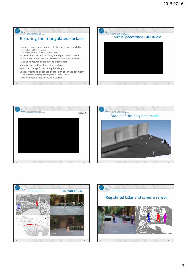
Output of the integrated model
i4D workflow
Registered Lidar and camera sensor
2015.07.16.
8
Multi target tracking and person re-identification based
on LIDAR
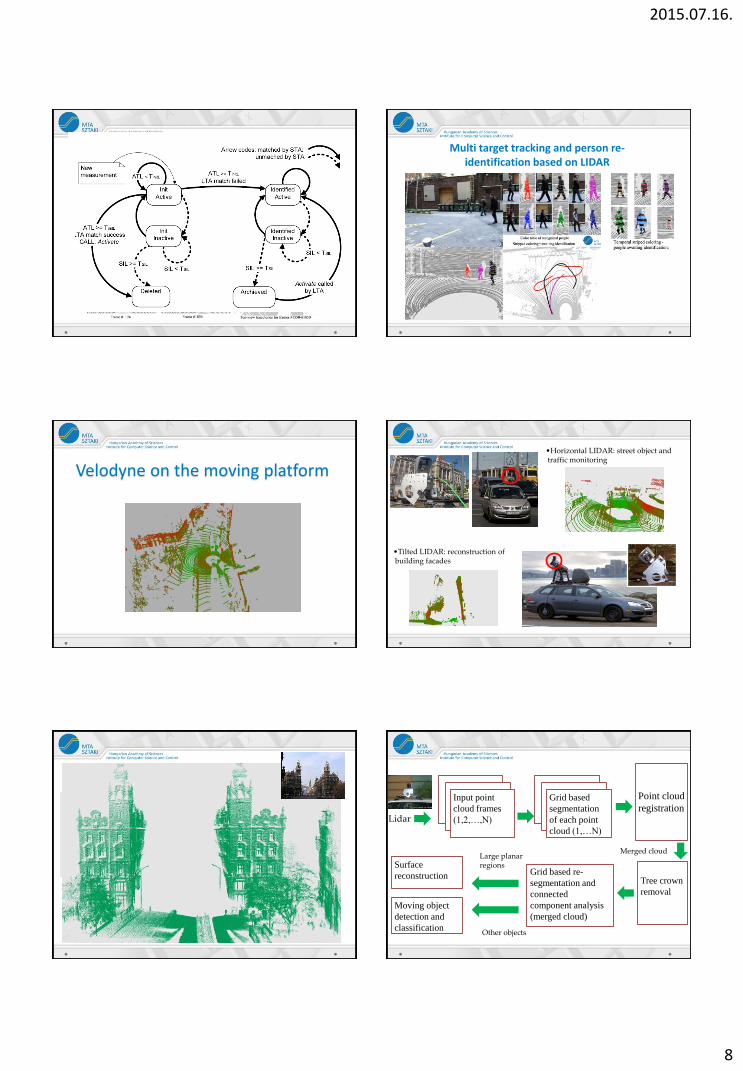
Multi target tracking and person re-identification based on LIDAR
Velodyne on the moving platform •Horizontal LIDAR: street object and traffic monitoring
•Tilted LIDAR: reconstruction of building facades
Grid based
segmentation
of each point
cloud (1,…N)
Lidar
Point cloud
registration
Tree crown
removal
Input point
cloud frames
(1,2,…,N)
Grid based re-
segmentation and
connected
component analysis
(merged cloud)
Surface
reconstruction
Moving object
detection and
classification
Large planar regions
Other objects
Merged cloud
2015.07.16.
9
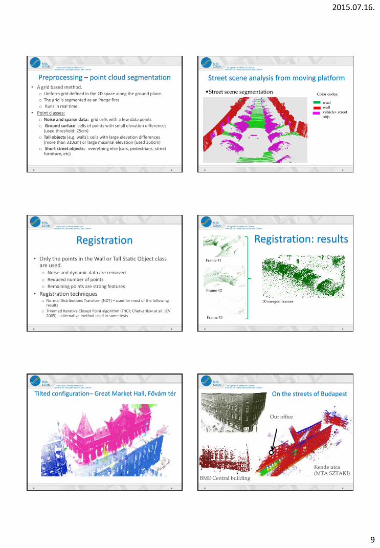
Preprocessing – point cloud segmentation • A grid based method.
o Uniform grid defined in the 2D space along the ground plane.
o The grid is segmented as an image first
o Runs in real time.
• Point classes: o Noise and sparse data: grid cells with a few data points
o Ground surface: cells of points with small elevation differences (used threshold: 25cm)
o Tall objects (e.g. walls): cells with large elevation differences (more than 310cm) or large maximal elevation (used 350cm)
o Short street objects: everything else (cars, pedestrians, street furniture, etc)
Street scene analysis from moving platform
•Street scene segmentation
road wall vehicle+ street objs.
Color codes:
Registration
• Only the points in the Wall or Tall Static Object class are used. o Noise and dynamic data are removed
o Reduced number of points
o Remaining points are strong features
• Registration techniques o Normal Distributions Transform(NDT) – used for most of the following
results
o Trimmed Iterative Closest Point algorithm (TrICP, Chetverikov at all, ICV 2005) – alternative method used in some tests
Frame #1
Frame #2
Frame #3
30 merged frames
Registration: results
Tilted configuration– Great Market Hall, Fővám tér On the streets of Budapest
Kende utca (MTA SZTAKI)
Our office
BME Central building
2015.07.16.
10
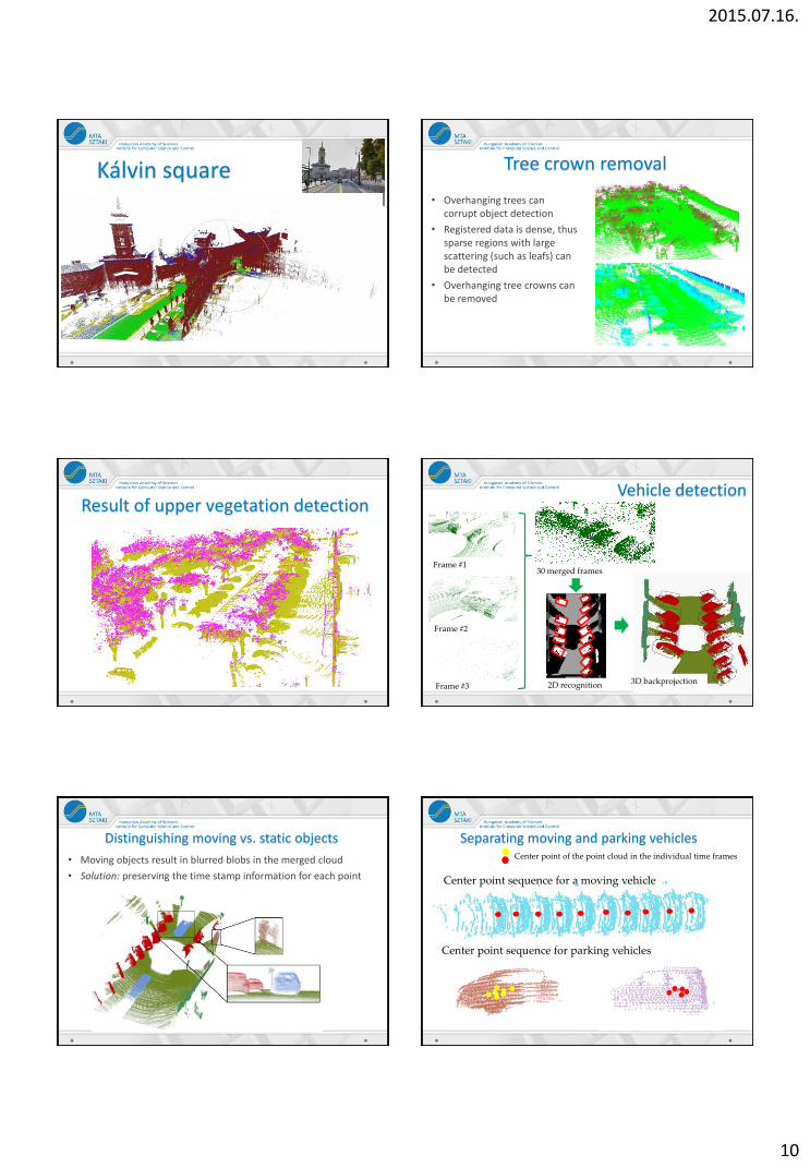
Kálvin square Tree crown removal
• Overhanging trees can corrupt object detection
• Registered data is dense, thus sparse regions with large scattering (such as leafs) can be detected
• Overhanging tree crowns can be removed
Result of upper vegetation detection
3D backprojection
Vehicle detection
Frame #1
Frame #2
Frame #3
30 merged frames
2D recognition
Distinguishing moving vs. static objects
• Moving objects result in blurred blobs in the merged cloud
• Solution: preserving the time stamp information for each point
Separating moving and parking vehicles Center point of the point cloud in the individual time frames
Center point sequence for a moving vehicle
Center point sequence for parking vehicles
2015.07.16.
11
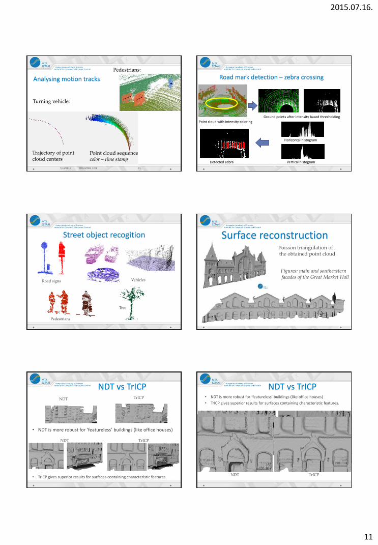
Analysing motion tracks
Turning vehicle:
7/16/2015 MTA SZTAKI / EEE 61
Trajectory of point cloud centers
Point cloud sequence color = time stamp
Pedestrians:
Road mark detection – zebra crossing
Vertical histogram
Horizontal histogram
Ground points after intensity based thresholding
Point cloud with intensity coloring
Detected zebra
Street object recogition
Road signs Vehicles
Pedestrians
Tree
Surface reconstruction
Figures: main and southeastern facades of the Great Market Hall
Poisson triangulation of the obtained point cloud
NDT vs TrICP
• NDT is more robust for ‘featureless’ buildings (like office houses)
NDT TrICP
NDT TrICP
• TrICP gives superior results for surfaces containing characteristic features.
• NDT is more robust for ‘featureless’ buildings (like office houses)
• TrICP gives superior results for surfaces containing characteristic features.
NDT vs TrICP
NDT TrICP
2015.07.16.
12
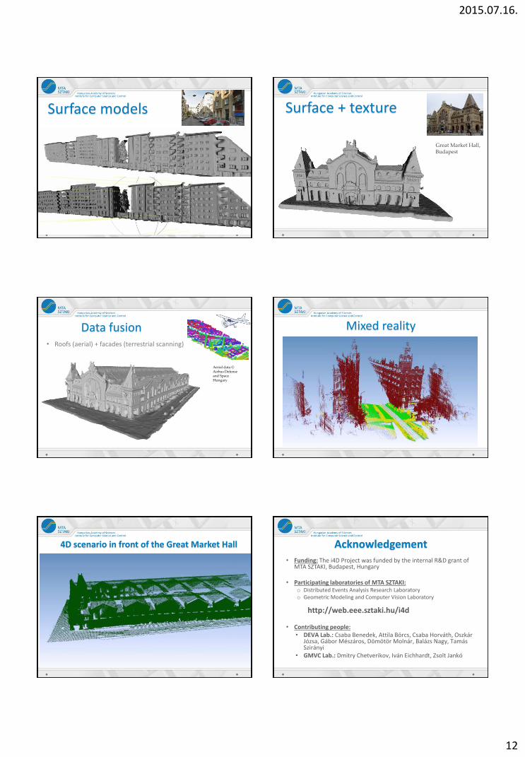
Surface models Budapest, Kende utca
Surface + texture
Great Market Hall, Budapest
Data fusion • Roofs (aerial) + facades (terrestrial scanning)
Aerial data © Airbus Defense and Space Hungary
Mixed reality
4D scenario in front of the Great Market Hall Acknowledgement • Funding: The i4D Project was funded by the internal R&D grant of
MTA SZTAKI, Budapest, Hungary
• Participating laboratories of MTA SZTAKI: o Distributed Events Analysis Research Laboratory o Geometric Modeling and Computer Vision Laboratory
http://web.eee.sztaki.hu/i4d
• Contributing people: • DEVA Lab.: Csaba Benedek, Attila Börcs, Csaba Horváth, Oszkár
Józsa, Gábor Mészáros, Dömötör Molnár, Balázs Nagy, Tamás Szirányi
• GMVC Lab.: Dmitry Chetverikov, Iván Eichhardt, Zsolt Jankó

2015.07.16.
13
Aerial Lidar: height map
LIDAR height map
Optical aerial image
© Astrium (Infoterra) HU
© Astrium (Infoterra) HU
186 m
180 m
175 m
169 m
163 m
157 m
151 m
145 m
Height:
3-D visualization
© Astrium (Infoterra) HU
Auxiliary channels
•Usage: texturing, vegetation detection
Optical aerial image
© Astrium (Infoterra) HU
© Astrium (Infoterra) HU © Astrium (Infoterra) HU LIDAR intensity map LIDAR echo map
http://web.eee.sztaki.hu/i4d/
Patent (HUN)
• Benedek Cs., Jankó Zs., Szirányi. T., Csetverikov D., Józsa O., Börcs A. és Eichardt I. "Eljárás és rendszer egyesített háromdimenziós modell előállítására", Hungarian Patent Office, No. P1300328, May 2013
o I
Publications • [C8] Cs. Benedek, Z. Jankó, Cs. Horváth, D. Molnár, D. Chetverikov and T. Szirányi: ”An Integrated 4D Vision
and Visualisation System,” International Conference on Computer Vision Systems, St. Petersburg, Russia, Lecture Notes in Computers Science, Springer, 2013
• [C7] A. Börcs, O. Józsa and Cs. Benedek: ”Object Extraction in Urban Environments from Large-Scale Dynamic Point Cloud Dataset,” IEEE International Workshop on Content-Based Multimedia Indexing (CBMI), Veszprém, Hungary, June 17-19, 2013
• [C6] O. Józsa, A. Börcs and Cs. Benedek: ”Towards 4D Virtual City Reconstruction From Lidar Point Cloud Sequences,” ISPRS Workshop on 3D Virtual City Modeling, Regina, Saskatchewan, Canada, May 28-31, 2013, to appear in ISPRS Annals of Photogrammetry, Remote Sensing and the Spatial Information Sciences
• [C5] Cs. Benedek, D. Molnár and T. Szirányi: ”A Dynamic MRF Model for Foreground Detection on Range Data Sequences of Rotating Multi-Beam Lidar,” International Workshop on Depth Image Analysis, Tsukuba City, Japan, November 2012, Lecture Notes in Computers Science, Springer, 2013
• [C4] J. Hapák, Z. Jankó, D. Chetverikov. GPU-Based Real-Time Spatio-Temporal Reconstruction Studio. In Proc. 28th Spring Conference on Computer Graphics, ACM, Smolenice, Slovakia, pp. 164-169, 2012.
• [C3] J. Hapák, Z. Jankó, D. Chetverikov, "Real-Time 4D Reconstruction of Human Motion", Proc. 7th International Conference on Articulated Motion and Deformable Objects (AMDO 2012), Mallorca, Spain, Lecture Notes in Computer Science, Springer, vol. 7378, pp. 250-259, 2012.
• [C2] C. Blajovici, D. Chetverikov, Z. Jankó, ”4D Studio for Future Internet: Improving Foreground-Background Segmentation”, IEEE International Conference on Cognitive Infocommunications, Kosice, Slovakia, 2012
• [C1] D. Chetverikov, L. Hajder, Z. Jankó, C. Kazó, J. Hapák ”Multiview 3D-4D Reconstruction at MTA SZTAKI”, IEEE International Conference on Cognitive Infocommunications, Kosice, Slovakia, 2012