Embed Size (px)
Citation preview
Sensor Fusion and Calibration of
Velodyne LiDAR and RGB Camera
Martin Veľas, Mi hal Špa ěl, et al.
Department of Computer Graphics and Multimedia,
Faculty of Information Technology,
Brno University of Technology

LiDAR = Light Detection and Ranging
HDL-32: 32 lasers scan the area
around the sensor
Beam is rotating (10Hz)
Field of view
Horizontal 360°
Vertical <-30°; +10°>
70m range, 2cm accuracy
What is Velodyne LiDAR?
2

Point cloud
Velodyne captures 700k points per each scan (7M pt/s)
Poi ts are orga ized i to the „ri gs“
ring = points captured by one lasser scanner/ray (32 rings)
The data provided by Velodyne
3

Merging the point cloud (with proper alignment)
3D reconstruction (GPU acceleration)
Creation of the environment map
Large data
Practical application (1/3)
4

Robotics
Navigation in 3D environment (using the map)
Obstacle avoidance
Object detection
Practical application (2/3)
5
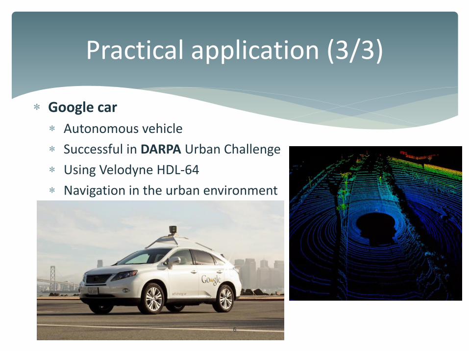
Google car
Autonomous vehicle
Successful in DARPA Urban Challenge
Using Velodyne HDL-64
Navigation in the urban environment
Practical application (3/3)
6
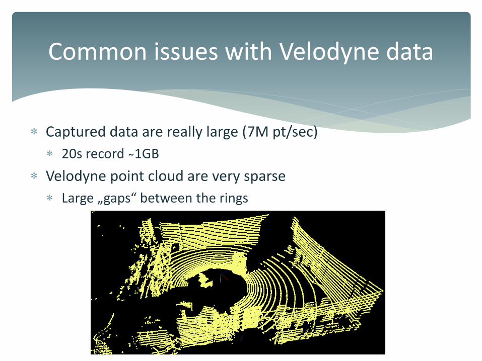
Captured data are really large (7M pt/sec)
20s record ̴1GB
Velodyne point cloud are very sparse
Large „gaps“ etwee the ri gs
Common issues with Velodyne data
7

We want to describe the point cloud by features
3D features:
Commonly based on the normals
How to compute the normal?
The neighbourhood of the
point are the points of the ring
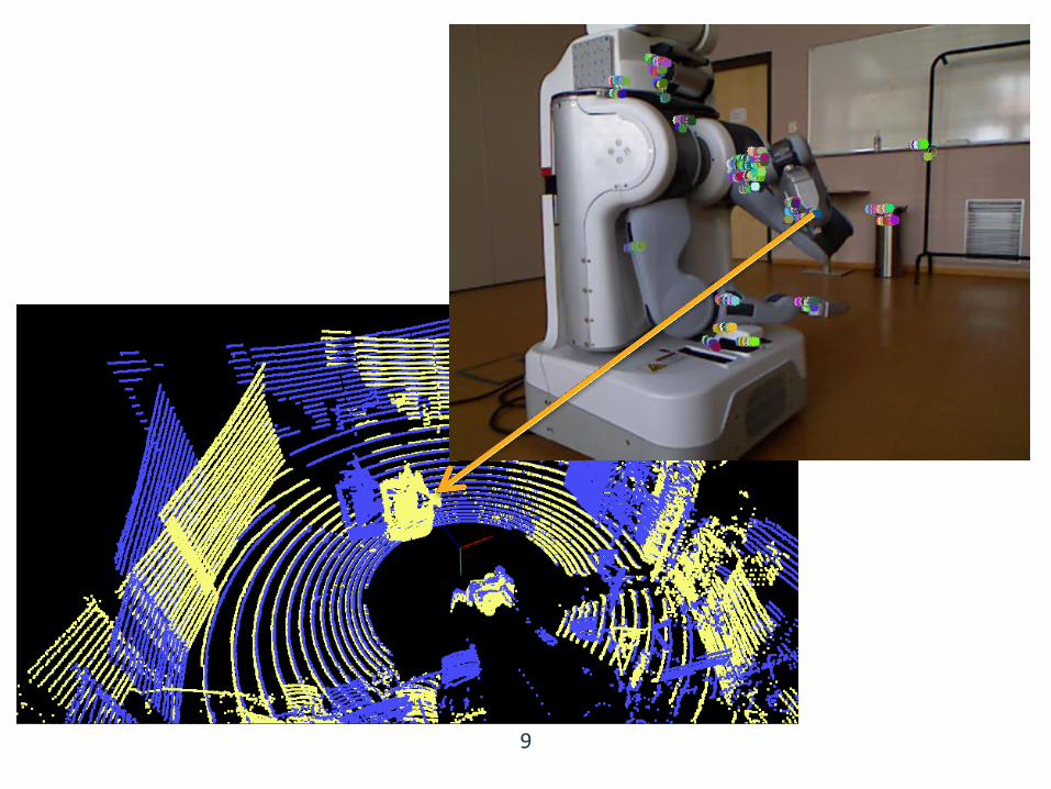
Fusion with other data could help
Color, image features, ...
How to extract features?
8
How to extract features?
9
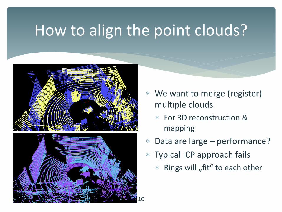
We want to merge (register)
multiple clouds
For 3D reconstruction &
mapping
Data are large – performance?
Typical ICP approach fails
Ri gs will „fit“ to ea h other
How to align the point clouds?
10

Different modalities
With other 3D scanner (Kinect, ToF camera, ...)
Dense point clouds of small area
Normals can be easily computed
With RGB camera
Colored point clouds
Image feature for
description
How to calibrate Velodye with other
sensors?
11
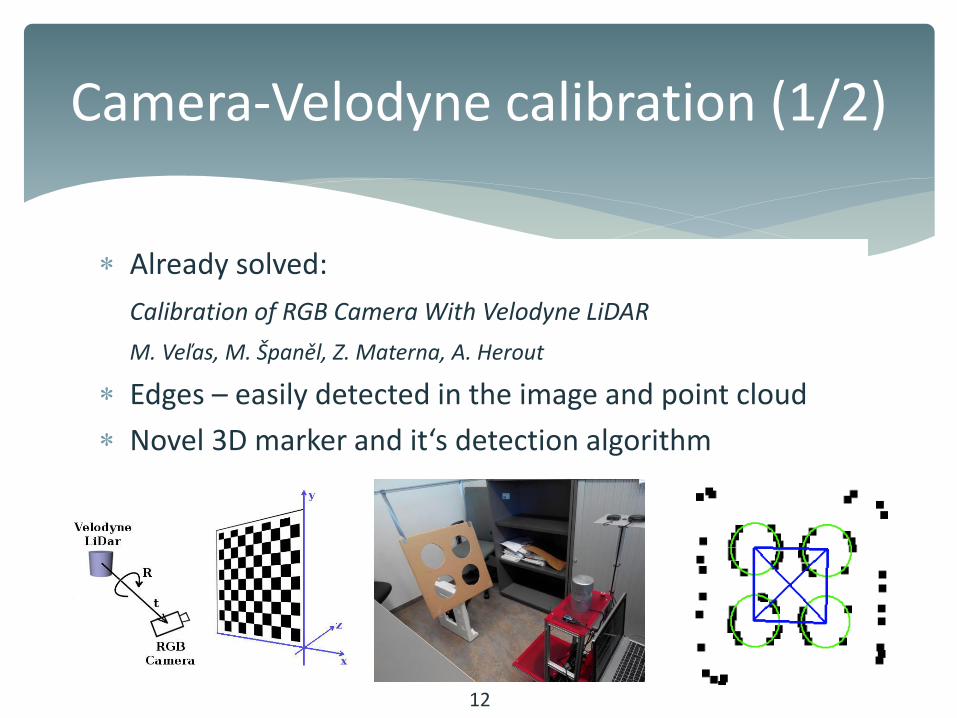
Camera-Velodyne calibration (1/2)
Already solved:
Calibration of RGB Camera With Velodyne LiDAR
M. Veľas, M. Španěl, Z. Materna, A. Herout
Edges – easily detected in the image and point cloud
Novel 3D arker a d it‘s dete tio algorith
12

Camera-Velodyne calibration (2/2)
3D marker is used for the coarse calibration
Refinement:
Grid search in small subspace of calibration parameters
5% lower miscalibration error as [LT13]
13

3D Visual odometry (1/5)
We need to register (merge) multiple point clouds
Visual odometry
How the robot was moving?
Pure:
Only camera images
2D features
With Velodyne
Depth information
14
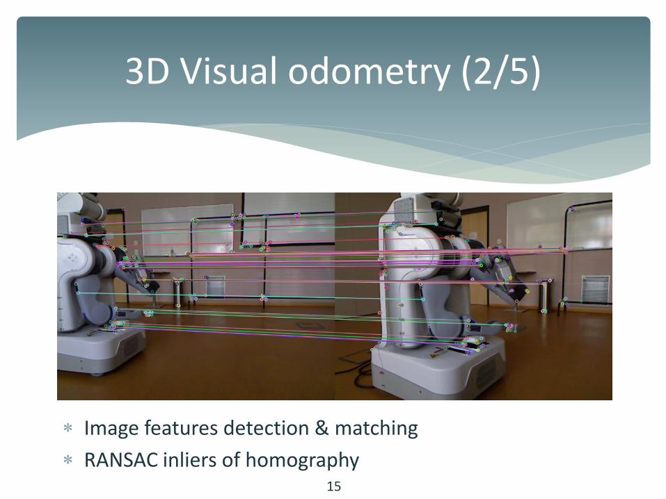
3D Visual odometry (2/5)
Image features detection & matching
RANSAC inliers of homography 15
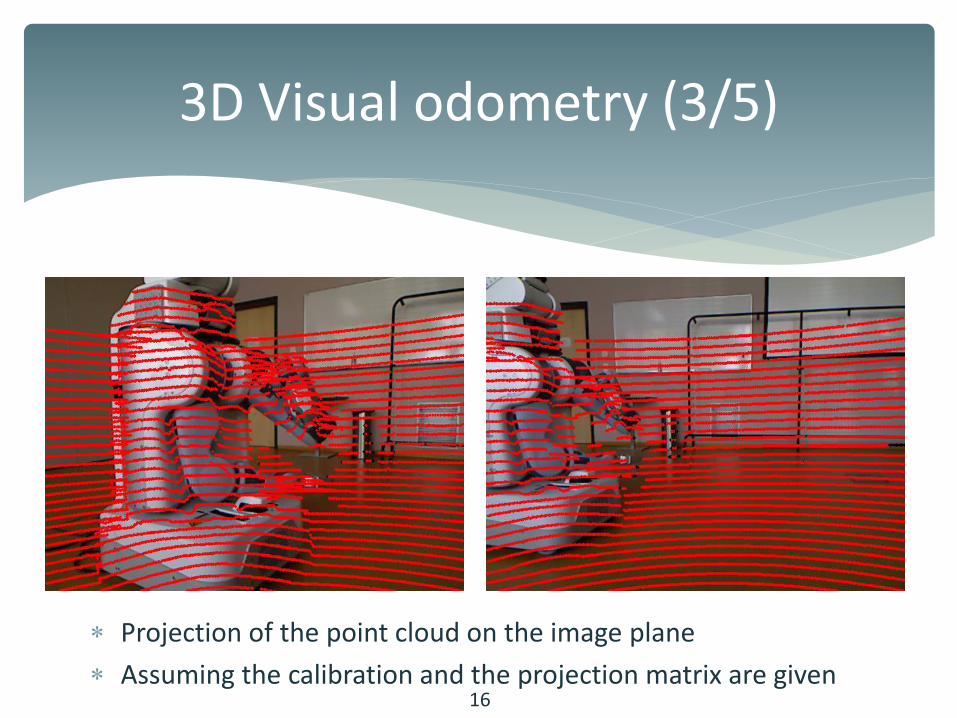
3D Visual odometry (3/5)
Projection of the point cloud on the image plane
Assuming the calibration and the projection matrix are given 16
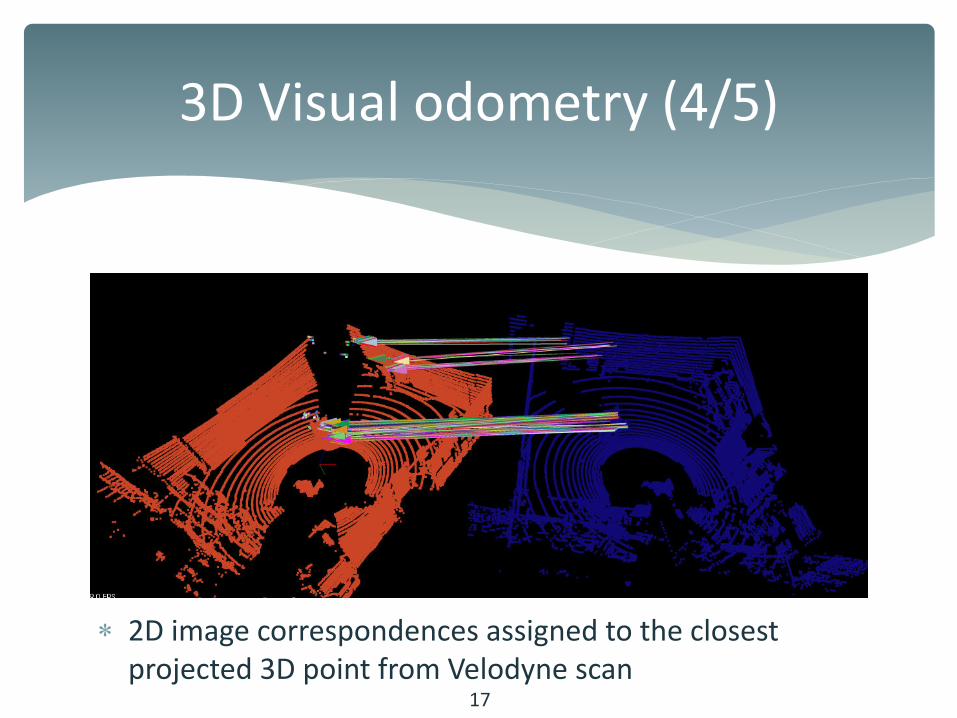
3D Visual odometry (4/5)
2D image correspondences assigned to the closest
projected 3D point from Velodyne scan 17
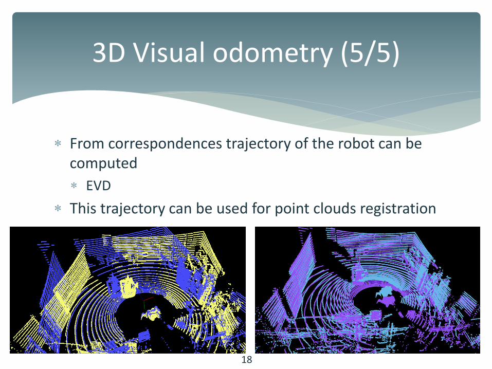
3D Visual odometry (5/5)
From correspondences trajectory of the robot can be
computed
EVD
This trajectory can be used for point clouds registration
18
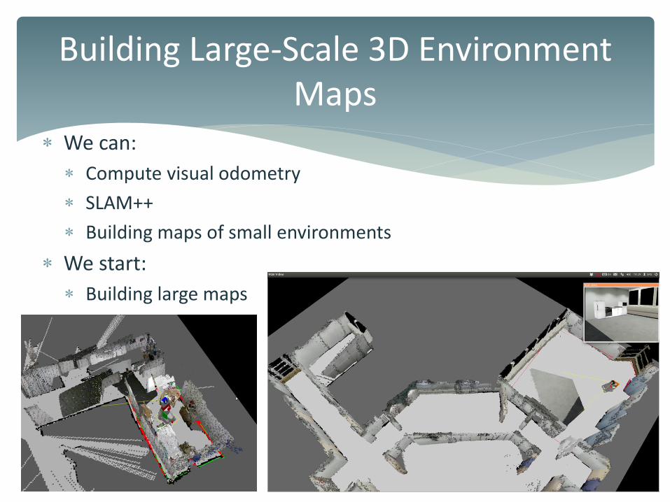
We can:
Compute visual odometry
SLAM++
Building maps of small environments
We start:
Building large maps
19
Building Large-Scale 3D Environment
Maps

Hierarchical scene representation
Dealing with (very) large pointclouds
Each one individual pixel can not be storred
OctoTree structure
Leaves = voxels (free/occupied)
OctoMap
Our improvements:
Better processing and
visualisation
plugins 20
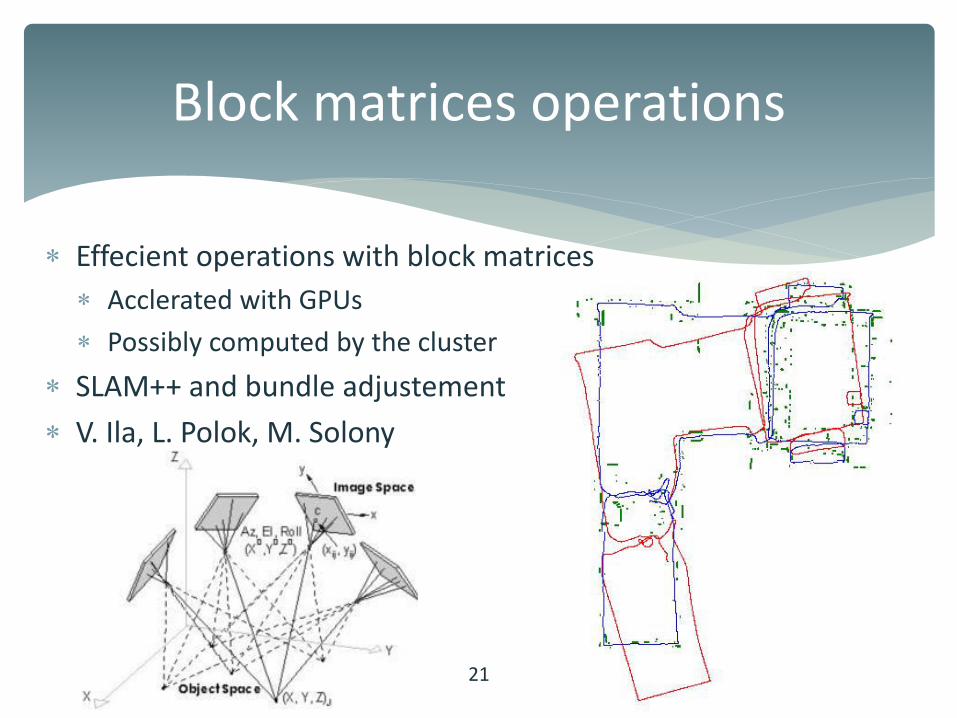
Effecient operations with block matrices
Acclerated with GPUs
Possibly computed by the cluster
SLAM++ and bundle adjustement
V. Ila, L. Polok, M. Solony
Block matrices operations
21
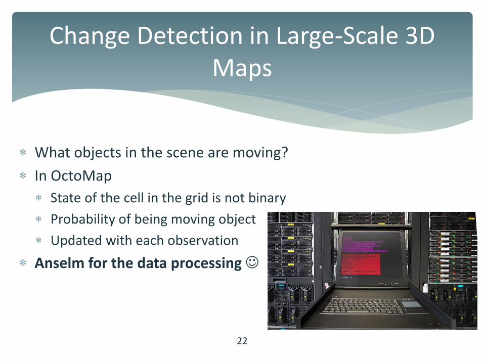
What objects in the scene are moving?
In OctoMap
State of the cell in the grid is not binary
Probability of being moving object
Updated with each observation
Anselm for the data processing
Change Detection in Large-Scale 3D
Maps
22
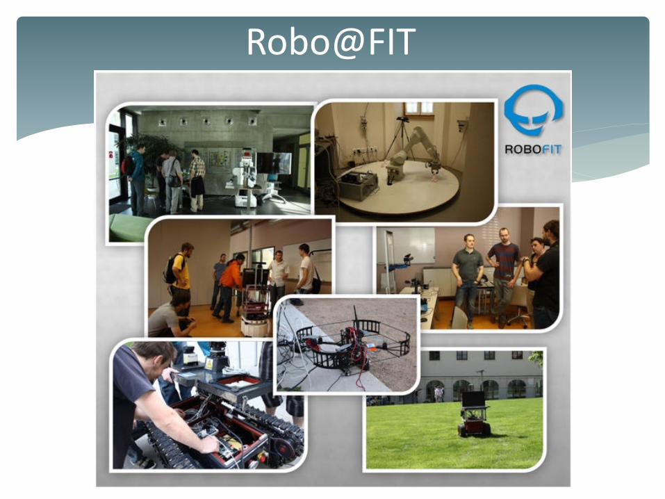
Robo@FIT