Embed Size (px)
Citation preview

VALIDATION OF THE CFX-4 CFD CODE FOR CONTAINMENT THERMAL-HYDRAULICS
M. Houkema, N.B. Siccama Nuclear Research and Consultancy Group NRG, Petten, The Netherlands
Abstract NRG uses the commercial CFD code CFX-4 for containment thermal-hydraulic analyses. Models to describe important physical phenomena such as condensation have been implemented by user coding. This paper describes these models. In addition, an overview is given of validation activities with the CFX4 model. Experimental results from the following sources have been used: the Kuhn condensation model; the PHEBUS test facility; the PANDA test facility; and the TOSQAN, MISTRA, and THAI test facilities within the OECD International Standard Problem 47. The CFX4 model predictions are fairly good. Deviations originate primarily from the applied wall treatment. Several recommendations for further development of CFD codes for containment thermal-hydraulics are therefore proposed. Introduction During a hypothetical severe accident in a nuclear power plant, which involves significant core damage, hydrogen can be generated and released into the containment. This may result in hydrogen concentrations sufficient to pose a threat of hydrogen deflagration or detonation. Such events could cause increases in containment pressure that could affect the containment integrity. Substantial international attention is paid to this hydrogen control issue, which is one of the key safety issues for nuclear power plants. In order to determine the risk associated with the hydrogen control issue, it is required to predict the hydrogen concentration in the containment during a severe accident. For this prediction, two thermal-hydraulic approaches can be used: the Lumped Parameter (LP) approach and the Computational Fluid Dynamics (CFD) approach. NRG has developed the LP code SPECTRA [1] and implemented a condensation model in the commercial CFD code CFX4. Calculations with both codes have been performed for full-scale NPPs. The present paper is about the use of CFX4. The NRG condensation model will be described and results of validation calculations are compared to experimental data. A brief overview will be given on the comparison of results with CFX4 versus experimental results from:
• the condensation in a vertical tube in the experiment of Kuhn et al. [2] • the PHEBUS test facility within the PHEBUS project, and PHEBEN-2 5th framework EU
project [3]; • the PANDA test facility within the TEMPEST 5th framework EU project [4,5]; • the TOSQAN, MISTRA, and THAI test facilities within the OECD International Standard
Problem 47 (ISP-47).
452
These experiments addressed several important thermal-hydraulic phenomena: wall condensation, atmospheric stratification, natural circulation, turbulent diffusion, and interactions between these phenomena. Model description The used CFD code is the commercially available program CFX4, developed by AEA Technology, nowadays owned by ANSYS. CFX4 is a general purpose CFD code. Below, the NRG condensation model is described. Driving force for wall condensation If steam condensation occurs, there is a net movement of gas towards the wall. This gas movement results in a convective flow towards the wall. This section describes how the convective flux is taken into account in steam condensation models. More background information can be found in chapters 16 and 17 of the book of Bird, Stewart and Lightfoot [6]. The mass balance of steam at the interface (subscript i) between gas and condensate film at the tube wall is: (condensation flux) = (steam transported with bulk motion) + (diffusive transport) (1) Suppose, the condensation flux at the wall is: (condensation flux) = ni (2) Consequently, the bulk motion of the gas to the interface is also equal to ni. The flux of steam that is transported with the bulk motion is therefore equal to: (steam transported with bulk motion) = ni · xi (3) In this equation, xi is the steam mass fraction at the interface. In a stagnant medium, the diffusive mass transfer between mass fractions x and xi is equal to: (diffusive transport) = gm · (x – xi) (4) In this equation, gm is the mass transfer coefficient. Substituting these equations in the mass balance results in: ni = ni · xi + gm · (x – xi) (5) Rearranging this equation results in:
)x1()xx(
gni
imi −
−⋅=
(6) Consequently, the driving force (BD) for steam condensation is equal to:
)x1()xx(
Bi
iD −
−=
(7)
453

NRG wall condensation model The NRG steam condensation model consists of sinks of steam, total mass, enthalpy and the turbulent quantities (k and ε or ω). These sinks are applied to grid cells adjacent to the walls and the sizes of the sinks depend on the steam condensation rate. The NRG steam condensation model is implemented in the user-Fortran of the CFX-4 code. Two user-Fortran subroutines are used: subroutine USRWTM is used to calculate the steam mass fluxes and subroutine USRSRC is used to define all sinks. In subroutine USRWTM, the steam mass fluxes at the condensing surfaces are calculated by the general formulation given by equation 6, which is here reformulated as equation 8. The mass transfer coefficient (gm) is a function of the turbulence near the wall, and is calculated in the CFX-4 code internally.
)x1(
)xx(gn
wall
wallcellmi −
−⋅= (8)
If the cells near the walls are sufficiently small, the mass transfer coefficient reduces to laminar transport:
yDgm⋅ρ
= (9)
The mass fraction of steam at the condense film surface (xwall) is calculated from the vapour pressure at the surface. The Antoine equation is used to describe the vapour pressure as a function of the surface temperature:
CT
BA)Pa1(
Pln+
+=⎟⎟⎠
⎞⎜⎜⎝
⎛ (10)
The coefficients A, B and C are fitted on data from steam tables. The result of this fitting process is A= +23.1512, B= –3788.02 K, and C= –47.3018 K. In subroutine USRSRC, the sinks of mass are defined. The steam sink as well as the sink of the total mass are modelled according to Equation 1. Furthermore, an enthalpy sink is required in order to remove the enthalpy associated with the mass of steam that is removed. It is assumed that the condensing wall immediately removes the condensation heat. In CFX-4, the enthalpy sink Q (in W) for each cell is calculated by: )TcTc(AnQ refbg,pcellst,pwalli ⋅−⋅⋅⋅= (11) In case mass is removed, the turbulent quantities associated with this mass must also be removed. The sinks of the turbulent quantities are calculated by:
⎪⎩
⎪⎨
⎧
ω⋅⋅=ε⋅⋅=⋅⋅=
ω
ε
cellwalli
cellwalli
cellwallik
AnSAnS
kAnS (12)
The diffusion coefficients used are obtained from the handbook of Vargaftik [7]. The diffusion coefficient of H2 is obtained from H2/N2 or H2/air systems. The diffusion coefficient for steam is obtained from steam/air or steam/N2 systems. The diffusion coefficients are determined for a constant temperature level and are kept constant during the calculation. For the laminar viscosity of the mixture also a constant value is used and is evaluated at average conditions. At present, NRG investigates the need for more advanced implementation of the diffusion coefficients.
454

NRG mist model Bulk condensation is the formation of mist from water vapour if the partial steam pressure is higher than the saturation pressure. In CFX4, bulk condensation has been modelled by an equilibrium reaction between water vapour and mist: H2O (v) H2O (l) The mist mass fraction has been defined as an Algebraic Slip Model (ASM) user scalar. The Algebraic Slip Model is a multiphase model in which the relative velocity of the phases, the slip velocity, is defined as a prescribed value. The slip velocity is the terminal velocity that mist droplets reach in a gravitational field. The magnitude of the slip velocity has to be based on an expected average mist droplet size. In every cell, which contains gas, the saturation pressure of water vapour is calculated. The saturation pressure is calculated by the Antoine equation. If the actual water vapour fraction in a cell is higher than the saturation fraction, the gas mixture is supersaturated and mist will be formed. If the water vapour fraction in a cell is lower than the saturation fraction, mist, if present, will evaporate. The gas density is a function of the mist mass fraction and is calculated by the following equation:
( )mistx1TRPM
+⋅⋅
=ρ (13)
The physical phenomena of rainout as well as deposition of mist on walls have been modelled. The rainout of mist is simulated by defining a slip velocity in the downward direction. The deposition of mist on surfaces is simulated by defining the mist concentration on wall to be equal to 0. Validation of the NRG condensation model with the Kuhn condensation model Kuhn et al. [2] investigated experimentally local heat transfer from condensation in the presence of non-condensable gases inside a vertical tube. The condenser tube has an inner diameter of 47.5 mm and is 3.37 m long. The tube consists of an adiabatic entrance of 0.81 m, followed by a 2.4-m long condensing section. Local heat fluxes are measured accurately at several locations in the tube. On the basis of the results obtained by Kuhn et al., they present physically based correlations for the heat and mass transfer of the vapour-gas side. The total heat transfer coefficient from the gas to the cooling water predicted by the correlations in their article is in close agreement with experimental values. The Kuhn model has the following shortcomings: the steam condensation rate may become undefined; entrance effects are not taken into account; free convection is not taken into account; and the gas temperature may fall below the saturation temperature. However, the model is useful to compare the NRG model with, because the entrance effect and the effect of free convection is small for the studied geometry. Unfortunately, the local heat fluxes are not presented in the article of Kuhn et al [2]. Therefore, the NRG condensation model is compared to the physically based correlations in the Kuhn article. In order to obtain a good comparison, the experimental apparatus is modelled in CFX-4 and the boundary conditions that are selected fall in the range that is used in the article. In order to obtain a sensible comparison between the models, the physical properties in both models are identical and a fixed condensing surface temperature was used. The inlet was modelled as an ‘Inlet Boundary’, with specified velocity, turbulence intensity and dissipation length scale. Nine two-dimensional computational meshes have been used in order to obtain y+ values between 0.5 and 200. The finest mesh contains 8500 cells and the CPU time for a steady-state calculation ranges from 1 second up to 20 minutes for the finest mesh.
455

Three turbulence models have been used for the CFD calculations: • the standard k-ε model • the low-Reynolds k-ε model • the k-ω model.
The first turbulence model requires preferably y+ > 20, while the latter two work best for y+ around 1. The influence of the y+ value on the results is presented below. Results of the Comparison Between the Two Condensation Models The results of the NRG CFX4 condensation model with different turbulence models are compared to the condensation model of Kuhn. The total condensation rates of both models are presented as a parity plot in 1. Different condensation rates are achieved by variation of the steam fraction and the temperature of the gas and the wall. Figure 1 shows that the difference between the CFX4 results and the condensation model of Kuhn is always less than 11 %. The standard deviation of all calculations is 3 %. The standard deviation of 6.4 % between the experimental heat transfer and the predicted heat transfer in the article of Kuhn [2].
1.E-04
1.E-03
1.E-02
1.E-01
1.E-04 1.E-03 1.E-02 1.E-01
Condensation rate of the Kuhn model (kg/s)
Con
dens
atio
n ra
te o
f the
NR
G m
odel
(kg/
s)
k-epsilonlow Re k-epsilonk-omegaparity line-20%+20%
Figure 1 Comparison with the Kuhn model
456
0.8
1.0
1.2
1.4
1.6
1.8
0.1 1 10 100y+ (-)
ratio
of c
onde
nsat
ion
rate
s C
FD/K
uhn
(-)
k-epsilonlow Re k-epsilonk-omega
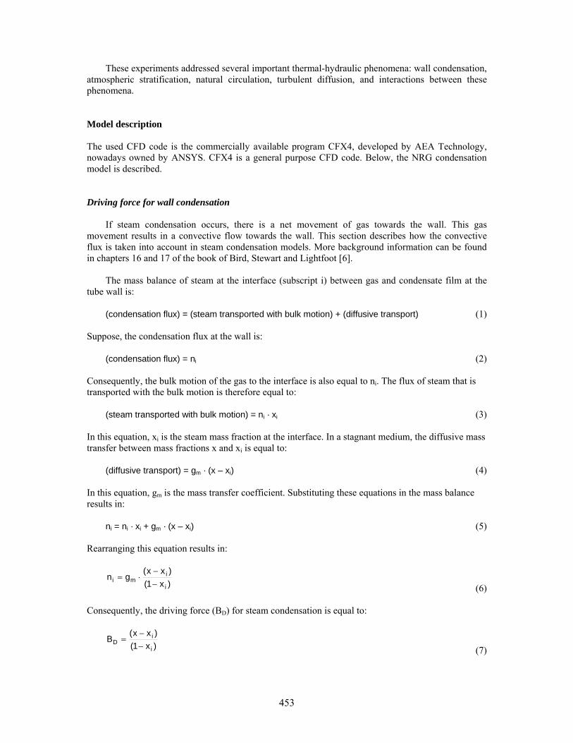
Figure 2 The influence of the y+ value at the wall on the calculation of the condensation rate. Influence of the Turbulence Model Figure 1 shows that the influence of the turbulence model on the condensation rate is negligible, provided that the y+ values are in the correct range. Influence of the y+ Value at the Wall It is well known that the y+ value has a large influence on boundary layer flows. In order to investigate the influence of the y+ value on the three turbulence models, nine different grids were used to model the experimental tube. The results of the calculations with different grids and the three turbulence models are shown in figure 2. This figure shows the ratio of the condensation rates calculated by CFD and the Kuhn model. The figure shows that the low-Reynolds k-ε and k-ω models perform best at y+ < 2. However, at higher y+ values – larger than about 5 – these low-Reynolds models show a sudden over-prediction of the condensation rate. The standard k-ε model works best at y+ > 20. At lower values, the condensation rate is over-predicted. Conclusions Kuhn comparison The NRG condensation model is compared to the physically based correlations described in literature, the Kuhn condensation model. The NRG model gives comparable condensation rates as the Kuhn model for a large range of conditions, like steam mass fractions between 30 and 99 %. The difference between the two condensation models is always less than 11 %. The standard deviation of all calculations is 3 %. The influence of the turbulence model on the condensation rate is negligible, provided that the y+ values are in the correct range. The low-Reynolds k-ε and k-ω models perform best at y+ < 2. At higher y+ values – larger than about 5 – these low-Reynolds models show a sudden over-prediction of the condensation rate. The standard k-ε model works best at y+ > 20. At lower values, the condensation rate is over-predicted. The standard k-ε model can be used up to at least y+ = 5000. The CFD result is independent of the y+ value at y+ < 2.
457
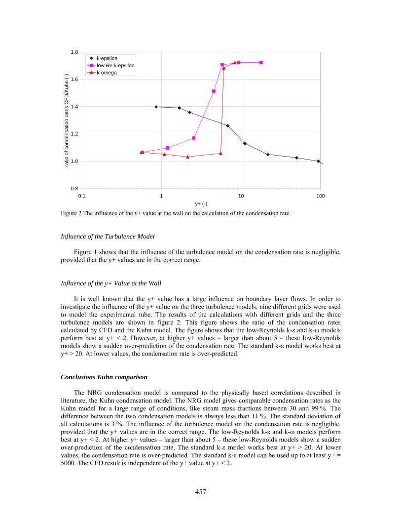
Validation against experiments in test facilities A shortcoming of the comparison with the Kuhn model is that only forced convection conditions are considered. In a full scale reactor containment, also free convection flows and combinations of forced/free convection boundary layers can be expected. Therefore, experiments have been performed in facilities representing small-size containments. NRG validated her condensation models in CFX4 for several of these experiments. An attempt has been made to follow the Best Practice Guidelines (BPG). If the Best Practice Guidelines are followed, independency of both mesh and time step are reached and proven. The mesh independency is proven by running the computation on at least three meshes. The first mesh has the largest cell size. In each following mesh, the cell size is halved, until the solution does not change between two consecutive meshes. Time step independency is proven by using different time steps until the solution does not change between two consecutive time steps. However, due to the large computational effort that they impose, the scope of the BPG has to be reduced for most applications. The PHEBUS test facility The NRG condensation model has been validated with experimental data from the PHEBUS test facility, as used within the PHEBUS FTP1 project, and within the PHEBEN-2 5th framework EU project; FTP0 [3]. Figure 3 presents the PHEBUS vessel, containing 3 condenser tubes. The low Reynolds number k-ω turbulence model and a structured grid have been applied. In this model the boundary layer is fully resolved and the condensation rate is calculated from diffusive flux to the condensers. Figure 4 shows the agreement between the calculated and measured condensation rates.
Figure 3 The structured mesh of the PHEBUS vessel, as used in the CFX4 model.
458

0.0E+00
5.0E-04
1.0E-03
1.5E-03
2.0E-03
2.5E-03
3.0E-03
0 2000 4000 6000 8000 10000 12000 14000 16000 18000 20000
time (s)
cond
ensa
tion
rate
at c
onde
nsor
(kg/
s)
ExperimentalComputed
Figure 4 The measured and predicted condensation rate for the PHEBUS FPT0 test. In both of the PHEBUS projects, the NRG predictions were in good agreement with the experiment. In addition to the presented prediction of the condensation rate, the calculated temperatures follow the experimentally observed trends of the temperatures, though the experimental variation was less than the calculated variation. The calculated pressure follows the experimental pressure closely. Summarising, validation of the code with the PHEBUS experiment showed very good results with the application of a low Reynolds number modification. This low Reynolds number k-ω turbulence model with full resolution of the boundary layers was selected for this validation, because near-laminar flow and free convection boundary layers were expected. The PANDA test facility NRG used the condensation model mainly in combination with the standard k-ε turbulence model with wall functions for other applications. In International Standard Problem 42 and in the 5th Framework Programme project TEMPEST (Testing and Enhanced Modelling of Passive Evolutionary Systems Technology for Containment Cooling) [4,5,9], experiments were performed in the PANDA facility. PANDA is a relatively large-scale thermal-hydraulic test facility, which can be used for investigating ALWR containment system behavior and related phenomena. Prototypical fluids such as water and steam are used as coolant at prototypical conditions. The total height of the facility is 25 m and it is designed for 10 bar and 200 ºC maximum operating conditions. In ISP42 it was concluded that the lumped parameter codes gave a systematic over-prediction of the containment pressure in PANDA. The CFX4 results of NRG showed that helium stratification occurred. This stratification, as presented in figure 5, explained the discrepancy between the experimental pressure and the pressure predicted with the lumped parameter codes.
459

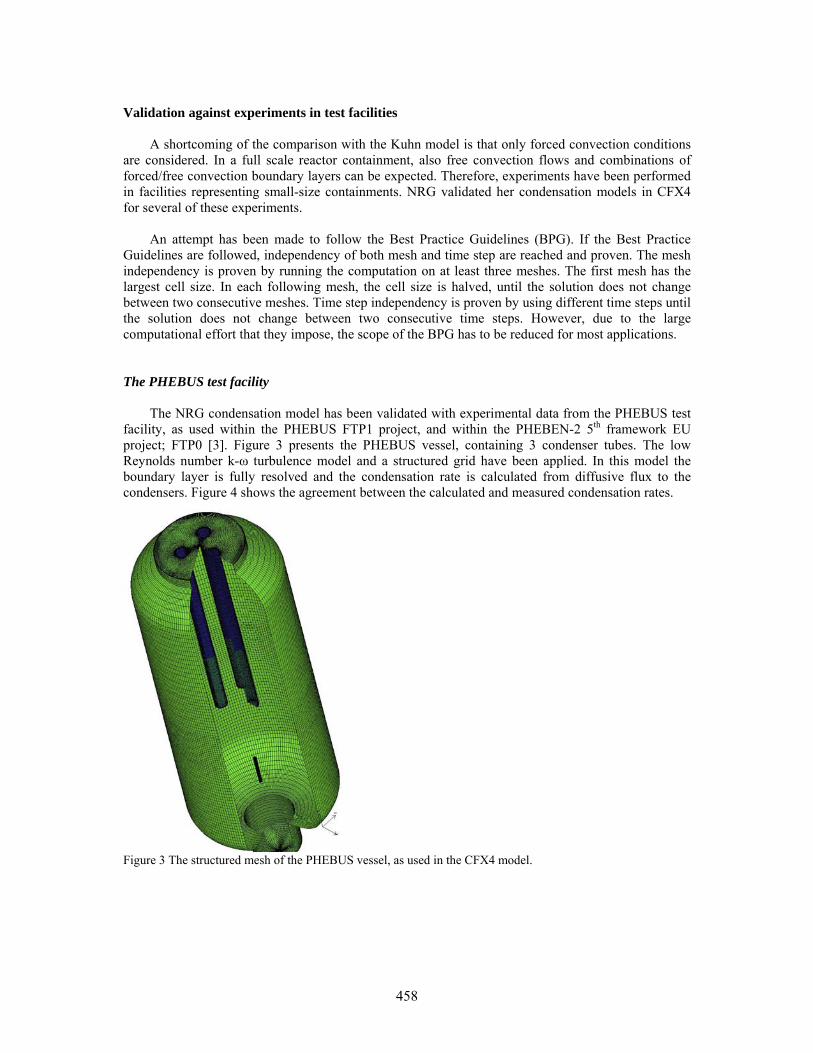
Figure 5 CFX4 prediction of helium stratification in the PANDA facility. TOSQAN, MISTRA and THAI facilities in International Standard Problem 47 In order to assess the capabilities of both approaches for the hydrogen control issue, the OECD has launched International Standard Problem 47 (ISP47). Within ISP47, experiments have been performed in the French facilities TOSQAN (IRSN) and MISTRA (CEA), and in the German THAI (Becker Technologies) facility. These experiments addressed several important thermal-hydraulic phenomena: wall condensation, atmospheric stratification, natural circulation, turbulent diffusion, and interactions between these phenomena. NRG participated in ISP47 by modelling of the TOSQAN experiment, as well as the MISTRA and ThAI experiments, again with application of standard k-ε turbulence models with wall functions. The TOSQAN test facility The TOSQAN facility [10] is a relatively small facility (7 m3). In the experiment, wall temperatures were regulated and central steam and helium injection took place. In CFX4, a 2-dimensional axi-symmetric model could therefore be applied. Several steam injection rates and phases were studied, as figure 6 reveals. This figure presents the experimental and calculated pressures (in bars) in the different phases of the ISP47 TOSQAN experiments. From this and other comparisons it was concluded that the CFX4 prediction was in fairly good agreement with the experiment [12].
460
1.00
1.50
2.00
2.50
3.00
3.50
4.00
0.00 5000.00 10000.00 15000.00 20000.00
Time (s)
Pres
sure
(bar
)
ExperimentNRG
Figure 6 Experimental and predicted pressure for the TOSQAN experiment. The MISTRA test facility The MISTRA test facility [11] is significantly larger than the TOSQAN facility: 100 m3 versus 7 m3. As for TOSQAN, central steam and helium injection took place. Cooled condenser plates were present in the facility. However, unintended spurious condensation on the containment wall occurred as well in the experiment. Since NRG’s model did not include this spurious condensation, NRG’s attempt to validate the CFX4 results by the MISTRA experiment was limited. Only the steady states were modelled. For the steam steady state NRG over predicted a pressure of 3.61 bar, where the measured value was 3.34 bar. In the helium-steam steady state, the predicted pressure was again higher than the experimental one: 5.70 bar versus 5.38 bar. Since the spurious condensation was not modelled, an over-prediction in the CFX4 result is expected. It is however not possible to quantify this expected over-prediction. The THAI test facility The THAI test facility is a 60 m3 vessel with several obstructions. In this way, the vessel is intended to represent a compartmented reactor containment. Figure 7 gives an impression of the THAI facility. The ISP47 experiment comprised of an upper helium injection phase, followed by an upper steam injection phase at another location. Then, horizontal steam injection took place in the lower part of the vessel. The fourth phase did not have any injections.
461
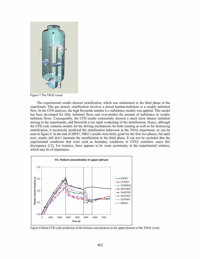
Figure 7 The THAI vessel The experimental results showed stratification, which was maintained in the third phase of the experiment. This gas density stratification involves a mixed laminar/turbulent or a weakly turbulent flow. In the CFD analyses, the high Reynolds number k-ε turbulence models was applied. This model has been developed for fully turbulent flows and over-predict the amount of turbulence in weakly turbulent flows. Consequently, the CFD results consistently showed a much more intense turbulent mixing in the experiments, and therewith a too rapid weakening of the stratification. Hence, although the CFD code contains models for the driving mechanisms for both creating as well as for destroying stratification, it incorrectly predicted the stratification behaviour in the THAI experiment, as can be seen in figure 8. In the end of ISP47, NRG’s results were fairly good for the first two phases, but until now, results still don’t maintain the stratification in the third phase. It can not be excluded that the experimental conditions that were used as boundary conditions in CFX4 somehow cause this discrepancy [13]. For instance, there appears to be some asymmetry in the experimental solution, which may be of importance.
H1: Helium concentration in upper plenum
0.0
0.1
0.2
0.3
0.4
0 1000 2000 3000 4000 5000 6000 7000
Time (s)
Hel
ium
Vol
ume
Frac
tion
(-) EXPBTCFXIJS2CFXNRG2DEFJNE2GASFZK2GASVEI2GOTNAI2phases
Figure 8 Blind CFD code prediction of the helium concentration in the upper plenum of the THAI vessel.
462

Conclusions To model the condensation heat and mass transfer in the presence of non-condensable gases in CFX-4, appropriate source terms have been implemented into the mass and energy balance equations by user-coding. These source terms are based on the steam concentrations gradients at the condensing surfaces. Furthermore, the assumption of an extremely thin liquid film has been made. Based on overall measured parameters such as system pressure and total condensate masses, it was concluded that condensation is predicted fairly well for the majority of validation cases presented in this paper. Deviations from the experimental results appear to originate primarily from the applied wall treatment, i.e., the treatment that is used to compute the near wall velocity, temperature, and concentration profiles. Within International Standard Problem 47, the following has been concluded [8]: NRG has demonstrated that results from using an “industrial CFD-code” are of the same quality as the ones obtained with “nuclear field codes”. NRG has used the commercially available CFD-code CFX4, which is, like STAR-CD and FLUENT, referred to as an “industrial CFD-code”. These codes are developed for a wide range of non-nuclear and nuclear applications. The so-called “nuclear field codes” are CFD-codes that have been specifically developed for nuclear containment thermal-hydraulics (like GASFLOW or GOTHIC). Before ISP47, it was believed that “nuclear field codes” were superior to “industrial CFD-codes”. Recommendations For further improvement of the CFD approach for containment-thermal hydraulic analyses, recommendations are given with respect to the following issues:
• Condensation: • Stratification: • Specific Best Practice Guidelines (BPG) for CFD containment thermal-hydraulic analyses.
In addition, recommendations are given for a combined CFD / LP approach for performing containment thermal-hydraulic analyses. Condensation When Stefan's law is used to calculate the condensation fluxes, the application of the automatic wall treatment would be an improvement. However, the application of this wall treatment does still not guarantee that the boundary layers are correctly represented. Therefore, the automatic wall treatment could be further improved by for example the application of an adaptive near wall mesh refinement. Concerning flow and heat transfer, the impinging jet has been widely used for turbulence modelling validation. It is recommended to determine what improvement can be made for thermal-hydraulics, especially in relation to mass transfer (i.e., condensation) modelling. Stratification Sub-models for turbulence damping due to stratification have already been developed for standard two-equation turbulence models. However, some controversy exists in the literature about the exact model formulations. It is recommended to determine whether the existing formulations are adequate for nuclear containment thermal-hydraulics. Furthermore, it is noted that more advanced three and four-equation turbulence models are presented in the literature, which are claimed to be
463

superior to standard two-equation turbulence models for complex buoyancy-driven flows. It is recommended to determine whether such more advanced models are really required for nuclear containment thermal-hydraulics. Mixed laminar / turbulent flows are often related to stratification. For such flows, low Reynolds modifications for turbulence models are available in CFD. However, they currently have to be used always together with full resolution of the boundary layers. Therefore, the application of low Reynolds modifications is currently often not practical. It is proposed to implement low Reynolds modifications in combination with the earlier discussed automatic wall treatment. Specific Best Practice Guidelines (BPG) for CFD containment thermal-hydraulic analyses. Present user guidelines and nodalisation rules for CFD codes must be expanded, and they must be applied. E.g. the turbulence simulation in the CFD models was not according to best practice guidelines. It is recommended to start an international activity to develop specific BPG for containment thermal-hydraulic CFD analyses. These BPG should amongst others include guidelines concerning jet modelling for containment thermal-hydraulics as well as guidelines for wall condensation. Combined CFD / LP approach Lumped Parameter codes have proven that valuable results can be obtained for containment thermal-hydraulics. LP codes will always require less CPU time than CFD, and thus are suitable for sensitivity calculations, which are required for nuclear reactor safety analyses that have to deal with the stochastic nature of initial and boundary conditions. Therefore, it is evident that LP codes will always remain the main workhorse for analysing containment thermal-hydraulic accident scenarios. However, LP codes have some inherent limitations due to the applied simplified flow model description. This results in a large user influence on LP code results, as evidenced in ISP47 by the large variation in the outcomes of LP code results. Therefore, combined use of both LP codes and CFD is recommended, where LP will act as the main workhorse for the containment analyses, whereas CFD is used to analyse a few selected accident scenarios which require more detailed analyses of the (local) phenomena that occur. In addition, it is recommended to use CFD to analyse a few selected critical accident scenarios which are difficult to analyse using LP codes due their inherent limitations. Possibly, the use of CFD can guide the LP code user in selecting the proper models and code parameters for bridging these limitations. The proposed combined approach requires some further development of both codes as discussed in the next sections. The overall objectives of the combined LP/CFD approach are to improve and guarantee the quality of the containment thermal-hydraulic analyses, and therewith to reduce the safety margins. In this way, containment thermal-hydraulic analysis will benefit from the best of both LP and CFD. References [1] M.M. Stempniewicz, “Simulation of Containment Transient Response During Accidents in
Advanced Reactor Types - The computer code SPECTRA”, PhD Thesis, NRG report 21437/00.52167/P, Arnhem, 12 May 2000
[2] S.Z. Kuhn, V.E. Schrock, P.F. Peterson, “An Investigation of Condensation from Steam - Gas Mixtures Flowing Downward inside a Vertical Tube.” Nuclear Engineering and Design 177 (1997), p. 53-69.
464

[3] N.B. Siccama, “CFD Simulation of the Flow Phenomena in the Phebus Containment during the FPT0 Release Phase.” SAM-PHEBEN2-T05, 20397/01.41354/C, NRG Petten, August 2001.
[4] J.A. Lycklama à Nijeholt, E.M.J. Komen, “Modelling ESBWR Passive Containment Cooling System Performance. CFD Analysis of Condensation and Helium Distribution in the PANDA Drywells.” NRG report 20407/03.53769/C, Petten, December 2003.
[5] E.M.J. Komen, S.M. Willemsen, F. Roelofs “Modelling SWR-1000 Building Condenser Behaviour. CFD Analysis of the PANDA BC4 Containment Phenomena.” NRG report 20407/03.53012/C, Petten, July 2003.
[6] R.B. Bird, W.E. Stewart, E.N. Lightfoot, “Transport Phenomena.” John Wiley, New York, 1960. [7] N.B. Vargaftik, Y.K. Vinogradov, V.S. Yargin, “Handbook of Physical Properties of Liquids and
Gases.” Begell House, New York, 1996. [8] V.A. Wichers, J.Y. Malo, J. Starflinger, M. Heitsch, G. Preusser, M. Tuomainen, M.
Huggenberger, Testing and enhanced modelling of passive evolutionary systems technology for containment cooling (TEMPEST), FISA, Luxemburg, 2001.
[9] K. Fischer et al., “International Standard Problem ISP-47 on Containment Thermal-Hydraulics. Step 2: ThAI. Volume 4: Comparison Report of Open Phases I-II-III-IV”, Becker Technologies GmbH, Eschborn, Report Nr. BF-R 70031-4, October 2005.
[10] Malet J., Porcheron E., Cornet P., Brun P., Norvez O., Menet B., Thause L. “ISP-47, International Standard Problem on Containment thermal-hydraulics, Step 1: TOSQAN-MISTRA, Phase A: air-steam mixtures TOSQAN experimental results.” IRSN Rapport DPEA/SERAC/LPMAC/02-45, Décembre 2002.
[11] D. Abdo et al. “ISP47 – Phase A – MISTRA experimental results”, CEA report 03-011/A. [12] Malet J., Porcheron E., Cornet P., Brun P., B. Menet, J. Vendel. “ISP-47, International Standard
Problem on Containment thermal-hydraulics, Step 1: TOSQAN-MISTRA, TOSQAN Phase B: air-steam-helium mixtures, Comparison Code-Experiments.” IRSN Rapport DSU/SERAC/LEMAC/05-19
[13] P. Royl, U. J. Lee1, J. R. Travis, W. Breitung, “Benchmarking of the 3D CFD Code Gasflow II with Containment Thermal Hydraulic Tests from HDR and Thai”, Forschungszentrum Karlsruhe, 2006.
465

466