Embed Size (px)
Citation preview
CFD modelling of doubleskin facades with venetian blinds
Ji, Y, Cook, M, Hanby, V, Infield, D, Loveday, D and Mei, L
Title CFD modelling of doubleskin facades with venetian blinds
Authors Ji, Y, Cook, M, Hanby, V, Infield, D, Loveday, D and Mei, L
Type Conference or Workshop Item
URL This version is available at: http://usir.salford.ac.uk/15842/
Published Date 2007
USIR is a digital collection of the research output of the University of Salford. Where copyright permits, full text material held in the repository is made freely available online and can be read, downloaded and copied for noncommercial private study or research purposes. Please check the manuscript for any further copyright restrictions.
For more information, including our policy and submission procedure, pleasecontact the Repository Team at: [email protected].
Proceedings: Building Simulation 2007
- 1491 -
CFD MODELLING OF DOUBLE-SKIN FAÇADES WITH VENETIAN BLINDS
Y Ji1, M J Cook1, V I Hanby1, D G Infield2, D L Loveday3 and L Mei3
1Institute of Energy and Sustainable Development, De Montfort University,
Queens Building, The Gateway, Leicester, LE1 9BH, UK 2Centre for Renewable Energy Systems Technology, Department of Electronic and Electrical
Engineering, Loughborough University, Loughborough LE11 3TU UK 3Department of Civil and Building Engineering, Loughborough University, Loughborough,
LE11 3TU UK
ABSTRACT
This paper describes CFD modelling of Double Skin Façades (DSF) with venetian blinds inside the façade cavity. The 2-D modelling work investigates the coupled convective, conductive and radiative heat transfer through the DSF system. The angles of the venetian blind can be adjusted and a series of angles (0, 30, 45, 60 and 80 degrees) has been modelled. The modelling results are compared with the measurements from a section of façade tested within a solar simulator and with predictions from a component based nodal model. Agreement between the three methods is generally good. Discrepancies in the results are generally caused by the simplification of the CFD model resulting less turbulence mixing within the façade cavity. The CFD simulation output suggests that the presence of the venetian blinds has led up to 35 percent enhancement in natural ventilation flow for the façade cavity and 75 percent reduction in heat loads for the internal environment. It was also found that little changes of the convective heat transfer coefficients on the glazing surfaces have been caused by the venetian blinds with different angles.
KEYWORDS Double Skin Façade, CFD, Natural convection, Solar radiation, Heat transfer.
INTRODUCTION The Double Skin Façade (referred to hereafter as DSF) is a concept known even in the early 1900s while serious research on measuring/predicting the performances of the DSFs did not begin until the late 1970s. Generally, DSFs consist of a pair of glass ‘skins’ separated by an air cavity. The air cavity can either be sealed, for conserving heat in winter, or ventilated for extracting the excess heat in summer. The latter can be achieved either mechanically or naturally. In the air gap between the two skins, solar shading devices such as venetian blinds are often used to improve the performance of the DSF. The potential benefits for using DSFs in commercial
buildings can be summarized as follows: a) fully glazed façades can improve the environmental aspects of a building and offer a better use of its perimeter area; b) by adjusting the cavity air flow and solar shading devices the DSF can reduce the building’s cooling and heating energy needs; c) a well performing DSF can improve the indoor environment by maximising the use of daylight, using natural ventilation, and controlling the solar shading device in order to prevent unwanted thermal gains. These beneficial aspects are the main reasons for the use of DSFs.
Three methods are normally used for investigating the performances of DSFs. Research using field experiments has shown that the use of a DSF may lead to a reduction in energy usage in summer of up to 15% by using natural ventilation and up to 30% in winter by using passive solar heating (Xu & Ojima 2007). Zollner et al (2002) conducted parametric studies of DSFs by varying the cavity depth in a full scale experiment. The work indicated that the buoyant air flow inside the façade cavity induced by solar radiation strongly depends on the ratio of the façade height to depth and the sizes of the ventilation opening into and out of the façade. Smaller scale DSF experiments by Ding et al (2005) also demonstrated the energy saving potential of using DSFs. Other researchers have used mathematical analysis to study the performance of DSFs, for example, the thermal network model used by Paassen et al (2000) and the component-based nodal model developed by Hanby et al (2006), were used to simulate heat transfer mechanisms through DSFs. Traditional experimental studies often lack flexibility to conduct parametric studies and the level of detail from the simple network models are limited. CFD modelling can potentially overcome these short-comings, although the resources needed for detailed 3D simulations can be significant. Most of the CFD simulations work conducted to investigate façades with venetian blinds has been 2D (e.g. Shahid & Naylor 2005, Naylor & Collins 2005). A 3D CFD simulation was conducted by Safer et al (2005) in which the venetian blinds were treated as porous

Proceedings: Building Simulation 2007
- 1492 -
media and the glazing elements as semi-transparent surfaces in order to reduce the mesh size. Marjanovic et al (2005) made other simplifications, such as reducing the façade width and height and increasing the thickness of the blind slats, in order to perform 3D simulations.
The purpose of this paper is to develop a CFD benchmark test case and to investigate the modelling challenges that exist when using CFD to model DSFs. The test case is based on a prototype façade which has been tested in the solar simulator at Loughborough University. The test facility (Figure 1) is located in an environmental chamber and consists of a solar generator, a DSF and a controlled internal environment located behind the inner glazing. The DSF consists of a single outer glazing element, venetian blinds and a double internal glazing element. The venetian blinds were situated at one-third of the façade depth as shown in Figure 2. The objectives of the present work are to use the commercial CFD code to model buoyant airflows resulting from thermal radiation, conduction and convection within the DSF and to validate the CFD modelling using experimental measurements. Comparisons have also been made with results from a component-based model based on this solar simulator.
Figure 1 The solar generator (left) and the DSF
(right) in the test chamber.
Figure 2 Schematic of the façade testing rig.
CFD MODELLING The commercial CFD code Ansys CFX10 (Ansys CFX 2005) was used to model air flow and heat transfer in this work. This package employs a coupled, multiple element (hex, tet, wedge and pyramid) and fully implicit solver using finite volume method. Primitive variables (velocity, pressure, enthalpy, etc) are defined at nodes at the corners of each element. Conservation equations are obtained by integration over the elements, creating arbitrary polyhedral control volumes about each node. The solver assembles one big matrix for the entire set of hydrodynamic equations (mass and momentum) and solves them simultaneously. In theory there is no upper limit for the time step due to the fully implicit discretization of the coupled equations and this will potentially speed up the calculation by using large time steps to reach a
steady state calculation.
Turbulence and radiation modelling
The Rayleigh numbers of the cases investigated in this paper are of the order of 109 to 1010, the buoyancy air flow in the façade cavity can not be characterized as strong turbulent flow (Ansys CFX 2005). In regions away from the glazing surfaces and venetian blinds, the airflow may be weakly turbulent or even laminar, however, the flow inside the façade cavity is dominated by the turbulent natural convection flow next to the glazing and blind surfaces, therefore it was decided to employ a turbulence model in the simulations. In this work, the k-omega model (Wilcox 1986) was used. The details of the conservation equations of mass, momentum, energy and the turbulence quantities can be found in Versteeg & Malalasekera (1995). The near wall treatment for k-omega based models is based on the
Single glazing
Blind Angle
d
D
P
L
Inte
rnal
env
ironm
ent
Double glazing
Sola
r gen
erat
or
tb
gs gd

Proceedings: Building Simulation 2007
- 1493 -
near wall formulation for low-Reynolds number computations. However, the k-omega models do not include the complex non-linear damping functions required in the k-epsilon formulations and are therefore more robust in terms of achieving convergence. The k-omega models allow a smooth shift from a low-Reynolds number model to a wall function formulation.
The radiation model used is the Monte Carlo (MC) model (Ansys CFX 2005). This model was chosen as it has been used successfully for a wide range of applications, particularly in cases where participating media and multiple domains with both transparent fluids and semi-transparent solids are present. The MC model simulates the physical interactions between photons and their environment. A photon is selected from a photon sourced and tracked through the system until its weight falls below some minimum at which point it ‘dies’. Each time the photon experiences a surface intersection, the physical quantities of interest are updated. This process generates a complete ‘history’ of that photon in the systems. Many photon histories need to be generated to get good estimates of the physical quantities of interest in a system which is time consuming. In order to reduce the computational costs radiation quantities are calculated on a coarse mesh compared with the hydrodynamic equations. The default coarsening rate is 64. However, large coarsening rates may cause statistic errors due to less radiation elements in the domain. In this work, the results are presented using 2,000,000 histories together with a targeting coarsening rate of 3. An under relaxation factor was used to further relax the radiation equation.
In the computing domain, glazing elements are modelled as semi-transparent solids and venetian blinds as opaque solids. The semi-transparent glazing elements are spectrum selective of radiation transfer: short wave radiation (solar) has a very high transmittance while long wave (thermal) radiation has a very low transmittance. This has been modelled using a ‘two-band’ spectrum model (Ansys CFX 2005). The solar band corresponds to wavelengths smaller than 2.7 microns and the thermal band to wavelengths larger than 2.7 microns.
Solar heat flux is generated from a solar generator which is located at a distance of 0.5m from the front of the facade. Only direct solar radiation is considered in the CFD model as the diffuse effects were expected to be negligible.
Geometry simplification and boundary conditions
The CFD geometry is simplified from the testing rig (Figure 1) by ignoring the curvature and swapping the ventilation inlet and outlet from one side to top and bottom (Figure 3). This simplification will potentially change the airflow pattern inside the
façade cavity but it can keep the thermal behavior the same as the rig and substantially reduce the mesh size which may limit the CFD calculation.
Geometrical information of the CFD geometry, using the notation in figure 2, is summarised in table 1
Table 1: Geometrical information (m) tb gs gd d P L D
0.001 0.012 0.028 0.08 0.072 2.05 0.55 Five blind angles were investigated: 0, 30, 45, 60 & 80 degrees.
Figure 3 Computing domain showing labels for
boundary conditions.
The boundary conditions imposed are as follows:
B1: Opening pressure for entrainment with a solar heat flux (715w/m2) as the boundary source for radiation modelling. This is to simulate the external environment.
B2: Opening pressure for entrainment and the local temperature ( inT =20°C). This is to simulate the internal environment.
B3: Static pressure and direction using the averaged opening temperature.
B4: Opening pressure and direction, and the local temperature ( inT =20°C).
B5: Adiabatic condition.
B6: Conservative interface flux for both heat transfer and thermal radiation.
B2 B1
B3 B3 B3
B4 B4 B4 B5 B5
B5 B5
B6 B6
B6 B6
B7
B7
Proceedings: Building Simulation 2007
- 1494 -
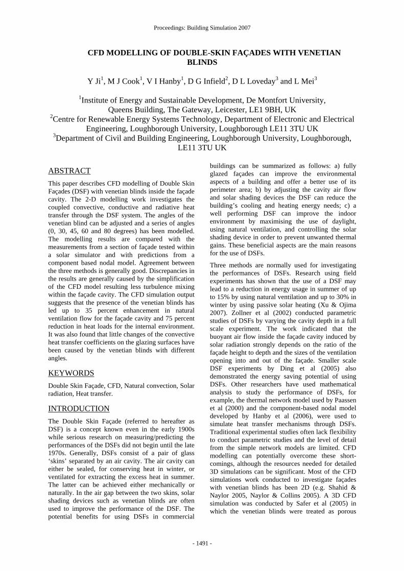
B7: Conservative interface flux for heat transfer and opaque surface for radiation (i.e. emissivityε =0.7)
Mesh dependency test
Mesh generation is very challenging for this type of geometry due to the huge differences between the smallest and the largest edge length scales. The ratio of the largest to the smallest edge lengths in the geometry investigated here is 2050. A large a mount of cells is needed to make a smooth shift from the largest and smallest cells. This is also the reason why three dimensional modelling is limited by the current desktop computing capability, particularly when radiation is modelled using ray tracing method which also considerably increases the computing overhead.
Figure 4 Mesh structure of the upper part of the
computing domain (a) and the detailed mesh of one slat and its surrounding (b).
A hybrid mesh was made by different software packages and the computer domain consists (from right to left) the external environment, the single glazing, the venetian blinds inside the façade cavity, the double glazing and the internal environment (Figure 4a). The structured mesh was made by ICEM (Ansys ICEM 2005) and the unstructured mesh with boundary inflation on individual slats was made by CFXmesh (Ansys CFX 2005). Only one cell was extruded from the third direction. 25 and 30 cells are subdivided within the single and double glazing
thickness and 5 layers of inflation are generated next to the slat surface. Only two cells are subdivided into the slat thickness assuming the temperature variation across the slat thickness are small due to its high conductivity (Figure 4b).
The total mesh elements used in this 2D modelling is around 110K with slight variations between different blind angles. A mesh of 200K was tested using the case of blind angle 45 degrees. The overall first order parameters are consistent with the mesh with 110K cells. Therefore the mesh of 110K cells was used for the simulations of all other blind angles.
Material properties
In each simulation, three types of materials are used: transparent media (air), semi-transparent solids (glazing) and opaque solids (venetian blinds). The material of glazing is toughened glass and the material of blinds is aluminium. The key parameters of these materials for airflow and heat transfer modelling are refractive index ( RI ), absorption coefficient ( α ), emissivity ( ε ) and conductivity ( λ ). These parameters are shown in table 2.
Table 2: Material properties α (/m) ε (-) λ (W/mK) RI (-)
Air 0.01 - 0.0243 1.0
30.0**Single Glazing 3000.0*
0.84 1.4 1.5
30.0**Double Glazing 1285.7*
0.84 0.042 1.5
Blinds - 0.7 120.0 - ** For wavelength 0.001~2.7 microns * For wavelength 2.7~1000 microns
Convergence control and criteria
In the solid regions it was necessary to use a timescale of 2 or 3 orders of magnitude higher than the timescale used in the air domains. This has the effect of accelerating the convergence rate for the energy equation in the solid domains. In this work, the maximum timescale of the air domains was 30s while the solid timescale is 500 multiplied by the timescale used in air domains. The large difference in the thermal conductivity between the air and the aluminum blinds can result in numerical round-off errors, which causes global imbalances of energy in the solid blinds to fluctuate. Therefore it was necessary to run the simulation in double precision to overcome this problem. It was also necessary to use a small under relaxation factor (URF=0.2) for the energy equations in the solid domains to help the convergence.
The criteria used for defining convergence are: i) that all the maximum residuals for each equation are
(a)
(b)

Proceedings: Building Simulation 2007
- 1495 -
lower than 5×10⁻⁴ for the last 100 time steps and ii) that the global domain imbalances for the energy equations in both the fluid and solid domains are less than 0.5%.
RESULT AND DISCUSSIONS The convergence criteria were achieved after about 500 to 700 iterations for all the cases considered.
Qualitative results
The temperature distribution within the computing domain with blind angle 45 degree is shown in figure 5. The thermal boundary layer of the domain next to the glazing/blind surfaces increases with the façade height. However, the thermal boundary layer is still very narrow at the top of the façade cavity, suggesting that the mixing within the domain due to natural convection is very weak.
Figure 5 Temperature field with blinds (45 degree)
Figure 6 shows the temperature in the middle of the DSF without and with blinds (angles are 0, 30, 45, 60, and 80 degrees). The difference in temperature of the double glazing due to the use of venetian blinds and the change in blind angles is clear. This indicates that the shading effects provided by the venetian blinds are accurately represented in the CFD model and predict that the temperature of the double glazing can be substantially reduced, even when the blind angle is zero (i.e blades almost horizontal).
Figure 6 The middle height temperature for cases without and with blinds for different slat angles.
Figure 7 The air flow field with blinds (45 degree)
Figure 7 shows the air flow vectors for slat angles at 45 degrees. All the other cases with blinds show a similar flow pattern. Strong turbulent flow around the blind slats forms a large upwards buoyancy momentum which drives air out of the top of the cavity. The presence of the venetian blinds not only offers the shading function but also enhances the natural ventilation of the façade cavity.
Quantitative results
Figure 8 shows a typical temperature profile at the mid-height of the domain for a blind angle of 45

Proceedings: Building Simulation 2007
- 1496 -
degrees. It can be seen that the surface temperatures of the glazing and blinds are increased dramatically due to the solar heat gains compared with the ambient (20C). The core (or bulk) temperature is close to the ambient which indicates that little mixing has taken place. The measured air temperature in the façade testing rig is always over 10°C higher than ambient. This discrepancy is thought to be due to the geometry simplification leading to less mixing than might occur in reality.
Figure 8 Temperature profile in the computational domain at mid height for slat angle of 45 degrees.
Figures 9-12 show the comparisons between experiments, CFD and a nodal model described by Hanby et al (2006). In the axis of blind angles the valid values are 0 to 90 degrees. Below this range, data points on the left show cases without blind. The single glazing temperature is taken to be the average temperature of the inner and outer glazing skins (figure 9). Experimental measurements and CFD predictions show some discrepancies (figures 9, 11 and 12). CFD under-predicted the temperature of the single glazing and double glazing outer layers (air cavity side), and over-predicted the temperature of the double glazing inner layer (internal environment side). The under-prediction in temperature may be due to the selection of the glazing properties such as absorption coefficients at solar and thermal bands. The absorption coefficients were estimated by its measured transmittance ( rT =0.70) using the Beer’s law relationship δα /)ln( rT−= , where δ is the thickness of the glazing. However, this parameter can change with glazing surface conditions leading to higher absorption coefficients than those used (table 2). The mixing level within the façade cavity in the CFD calculations is much smaller than the testing rig which may be another reason for the under-prediction in temperature using CFD. Although the aim was to maintain the test room at 20°C, it was observed that local temperature variations were exist, for example, one monitoring temperature sensor at the air intake position of the testing rig show around 2°C higher than ambient. This may have contributed further for the under-prediction in temperature using CFD simulations.
Figure 9 Variation of temperatures with blind angles
for single glazing surface.
Figure 10 Variation of temperatures of blind
surfaces with blind angles.
Figure 11 Variation of temperatures with blind angles for double glazing outer surface (façade
cavity side). The surface temperatures of the blinds predicted by the CFD model agreed well with measurements except at the zero blind angle (figure 10). For zero angle the thermocouple may have been partially exposed to the direct solar radiation while for larger blind angles it was easier to locate the thermocouples on the opposite side of the slats to that of the solar generator, thus avoiding the direct solar effects.
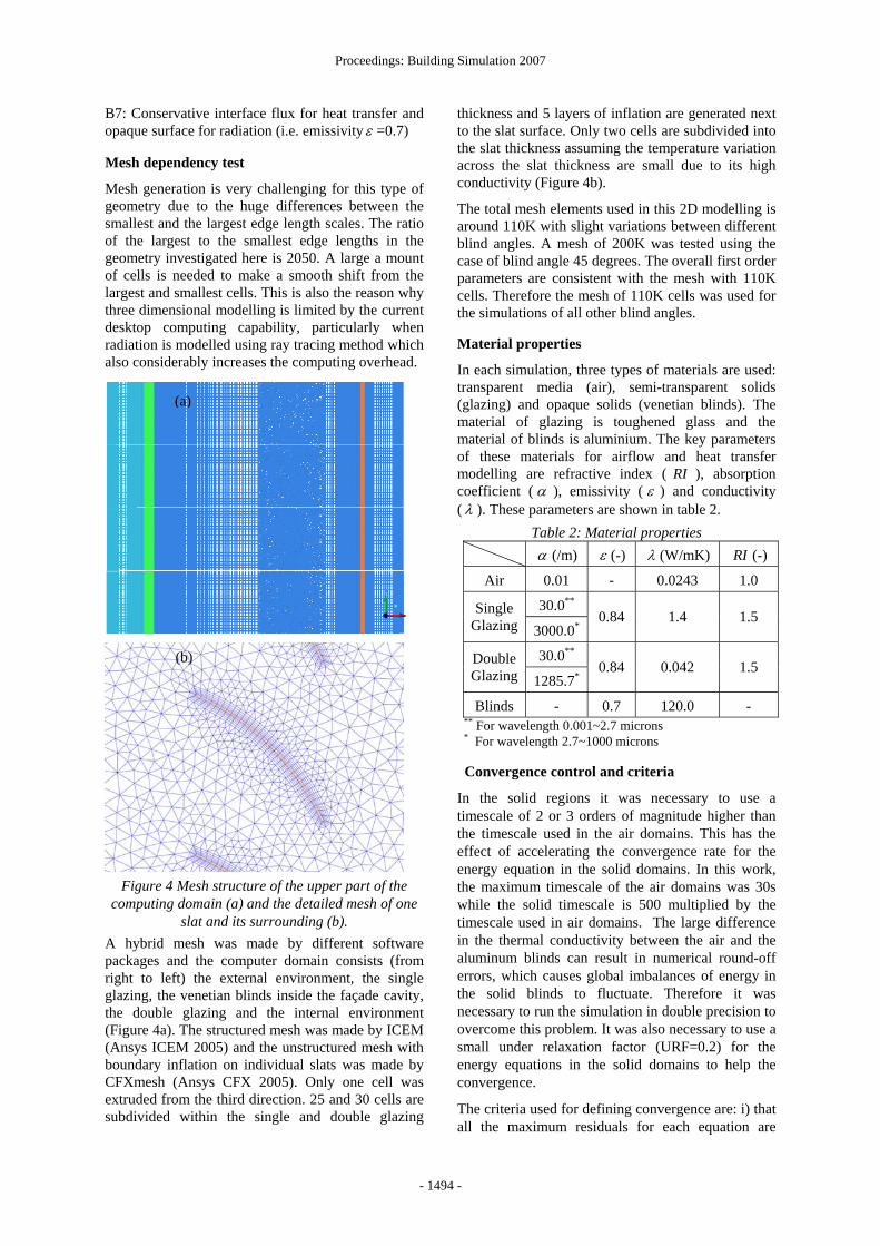
In reality the double glazing used in the testing rig comprises two 6mm toughened glass separated by a 16mm air gap. There is also a layer of low-e coating to increase thermal resistance located on the toughened glass at inner environment side which was not included in the CFD simulation. It was unable to
Proceedings: Building Simulation 2007
- 1497 -
consider the effect of the low-e coating, which may be the reason for the over prediction of the double glazing surface temperature at the inner skin (figure 12).
Figure 12 Variation of temperatures of the double
glazing inner surface with blind angles. For the solar heat flux investigated (715W/m2) only small differences were observed for the convective heat transfer coefficients (CHTCs) with and without blinds (figure 13). With changes of blind angles, the CHTCs on the double glazing surfaces experience periodic oscillations due to the presence of the venetian blinds, i.e. points on the glazing surface which correspond to the close proximity of a blind slat show higher/lower CHTC. However the mean value of this parameter remained similar for cases without and with blinds (less than 5% difference). This indicates that the presence of venetian blinds does not impose a great effect on the CHTCs. This is thought to be due to the location of the blinds at one-third of the cavity width closer to the single glazing element which means the turbulent boundary layer caused by the blinds is sufficiently thin so as not to overlap with the thermal boundary layer of the glazing surfaces. For cases where the blinds are very close to the glazing layers, the CHTCs can be enhanced (Shahid and Naylor 2005). It is worth noting that the non smoothness of the CHTC profiles may be partially due to the statistic error from the MC radiation model. This non smoothness can be improved by increasing the number of histories and radiation elements in the computing domain, and by using a smaller under-relaxation factor for the radiation equation. The drawback of doing this is potentially significant increase in the computing time required.
Figure 13 Convective heat transfer coefficients on
the glazing surfaces with and without blinds (Line 1 to Line 4 are vertical lines on the middle of the
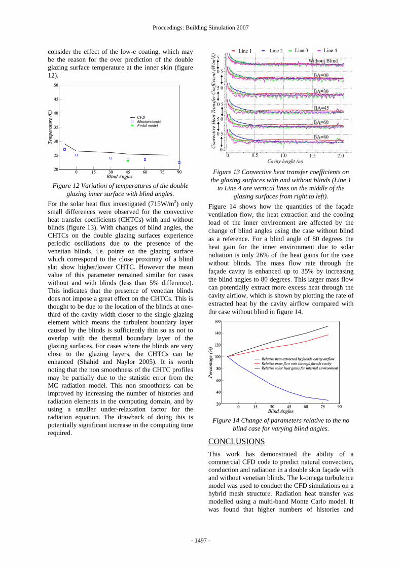
glazing surfaces from right to left). Figure 14 shows how the quantities of the façade ventilation flow, the heat extraction and the cooling load of the inner environment are affected by the change of blind angles using the case without blind as a reference. For a blind angle of 80 degrees the heat gain for the inner environment due to solar radiation is only 26% of the heat gains for the case without blinds. The mass flow rate through the façade cavity is enhanced up to 35% by increasing the blind angles to 80 degrees. This larger mass flow can potentially extract more excess heat through the cavity airflow, which is shown by plotting the rate of extracted heat by the cavity airflow compared with the case without blind in figure 14.
Figure 14 Change of parameters relative to the no
blind case for varying blind angles.
CONCLUSIONS This work has demonstrated the ability of a commercial CFD code to predict natural convection, conduction and radiation in a double skin façade with and without venetian blinds. The k-omega turbulence model was used to conduct the CFD simulations on a hybrid mesh structure. Radiation heat transfer was modelled using a multi-band Monte Carlo model. It was found that higher numbers of histories and
Proceedings: Building Simulation 2007
- 1498 -
radiation elements are needed to achieve convergence when conducting a steady state calculation. A small under-relaxation factor for radiation equations was also found useful for assisting convergence.
The predicted trends in glazing and blind surface temperatures of the two dimensional CFD model are compared favourably with those of the experimental measurements and the nodal model. Further investigations are underway to perform parametric studies such as changing the glass material properties, blind surface emissivities, location of blinds and width of the façade cavity.
There were discrepancies in both quantitative and qualitative behaviours of the CFD model when compared with the experiments. This is likely to be due to simplifications in the geometry leading to less turbulence and mixing than occurred in the experiments. A three dimensional CFD model with the exact façade testing rig may be needed in order to represent the real physics. However, the mesh size of a three dimensional calculation of cases considered in this paper were far beyond the current desktop computing capability.
CFD simulation results showed that the presence of venetian blinds had little effect on the convective heat transfer coefficients at the glazing surfaces. They also demonstrated that the natural convection airflow inside the façade cavity was enhanced by increasing the blind angles. As a result, more excess heat can then be extracted, further reducing the cooling load of the internal environment and enhancing the performance of the double skin facade.
ACKNOWLEDGMENT The authors would like to acknowledge the financial support received from the Engineering and Physical Sciences Research Council, UK via grants GR/S02396/01 and GR/S02389/01. We would also like to acknowledge the initial contribution of Dr Ljiljana Marjanovic to both the CFD and nodal network modelling, and our partners in the project, Ove Arup & Partners and IT Power Ltd.
REFERENCES Ansys CFX 2005 version 10, user manual,
www.ansys.com/products/cfx.asp
Ansys ICEM 2005, version 10.0.1, user manual, www.ansys.com/products/ icemcfd.asp
Ding W, Hasemi Y, and Yamada T. 2005. “Natural ventilation performance of a double-skin façade with a solar chimney” Building & Environment, 37, pp. 411-418.
Hanby VI, Cook MJ, Infield DG, Ji Y, Loveday DL, Mei L, and Holmes MJ. 2006. “Nodal network
and CFD simulation of airflow and heat transfer in double skin facades with blinds” Paper 23, Proceedings of System Simulation in Buildings 06, University of Liege, Liege, Belgium.
Marjanovic L, Cook MJ, Hanby VI, and Rees S. 2005. “CFD modelling of convective heat transfer from a window with adjacent venetian blinds” the Ninth International IBPSA Conference, pp. 709-716, Montreal, Canada.
Naylor D. and Collins M. 2005. “Evaluation of an approximate method for predicting the U value of a window with a between-panes blind” Numerical Heat Transfer, Part A, 47, pp. 1-18.
Paassen D. and Voorden MVD. 2000. “Development of simplified tools for evaluation energy performance of double façades” the International Building Physics Conference, Eindhoven, September.
Safer N, Woloszyn M, and Roux JJ. 2005. “Three-dimensional simulation with a CFD tool of the airflow phenomena in single floor double-skin façade equipped with a venetian blind” Solar Energy, 79, pp. 193-203.
Shahid H. and Naylor D. 2005. “Energy performance assessment of a window with a horizontal venetian blind” Energy & Buildings, 37, pp. 836-843.
Versteeg HK. and Malalasekera W. 1995. “An introduction to computational fluid dynamics – the finite volume method” Longman Group Ltd 1995. ISBN 0-582-21884-5.
Wilcox DC. 1986. “Multiscale model for turbulent flows” AIAA, the 24th Aerospace Sciences Meeting. American Institute of Aeronautics and Astronautics.
Xu L. and Ojima T. 2007. “Field experiments on natural energy utilization in a residential house with a double skin façade system” Building & Environment, 42, pp. 2014-2023.
Zollner A, Winter ERF, and Viskanta R. 2002. “Experimental studies of combined heat transfer in turbulent mixed convection fluid flows in double-skin-facades” International Journal of Heat and Mass Transfer, 45, pp. 4401-4408.