Embed Size (px)
Citation preview

Disclaimer
ANSYS and ANSYS CFX are registered trademarks or trademarks of ANSYS, Inc. or its subsidiaries located in the United States or other countries. All registered trademarks are property of their respective owners. This tutorial is not approved or endorsed by ANSYS Inc., the owner/producer of the CFX software and owner of the ANSYS® trade mark.
Summary
The primary objective of this tutorial is to guide the user using ANSYS CFX through the CFD simulation of lobe pump using immersed body solver.
The objective of this simulation is to determine the velocity and pressure fields produced when a fluid flows through lobe pump.
Prerequisites
You will need to download following 3 mesh files (.cfx5) freely available on FetchCFD at: http://fetchcfd.com/view-project/730
- Lobe-Pump-Lobe-1-Mesh.cfx5, - Lobe-Pump-Lobe-2-Mesh.cfx5
- Lobe-Pump-Casing-Mesh.cfx5

Problem Description
The sketch of the problem is shown below. The task is to model the flow around the rotating lobes in a lobe pump. Air is pulled through a pair of cycloidal lobes and is trapped in pockets surrounding the lobes and carried from the inlet side to the outlet side. Lobes are rotating in opposite direction at a speed of 23 rev/s around z-axis.
Inlet Outlet
Lobe
Casing

Overview
Pre-processing
Importing mesh (.cfx5) files created in the ICEM into the CFX pre-processor. Defining the problem and setting-up boundary conditions.
Simulation Run
Lauching the CFX-Solver and running the simulatoins.
Post-Processing
Importing the results (.res) in CFD-post and post-processing results.

Simulation Pre-processing

Step 1: Launch CFX Pre-processor (Windows > All apps > ANSYS 15.0 > CFX 15.0)
Step 2: Click: New Case > General
Note: In case of Information window
shows up just click ok
Note: In Working Directory set the path
where you want to save your
simulations a
b
c
d

Mesh
Step 3: Mesh > Import Mesh > ICEM CFD
A: Import mesh files (.cfx5) for lobes (Lobe-Pump-
Lobe-1-Mesh.cfx5 and Lobe-Pump-Lobe-2-
Mesh.cfx5) and the casing (Lobe-Pump-Casing-
Mesh.cfx5) into CFX pre-processor. Make sure
mesh units are mm.
a
b c
d
Note: For this tutorial these mesh files
are fine but for a simulation
analysis/study it is recommended to
perform mesh sensitivity study.

Immersed Solid Domain Definition
Step 4: Insert Domain name LOBE1 by left clicking on Domain and typing
“LOBE1” in the Insert Domain pop-up window
a
b

Step 5: Select the mesh for the LOBE1 by left clicking on
Location tab and then selecting (ctrl + left mouse click) “BODY
LOBE1”, “BODY LOBE1 2”, “BODY LOBE1 3” Domain. Click OK.
Step 6: Next select Immersed Solid in the Domain Type
a
b
d
c

Step 7: Set Option under Domain Motion to Rotating and give an
angular velocity of 23 rev/sec
Step 8: Next set Option under Axis Definition to Two Points and fill
the following values:
Rotation Axis From > -0.078887, 0.18419, 0
Rotation Axis To > -0.078887, 0.18419, 1
Click OK
a
b
c
Note: These are local center of gravity points for LOBE1. These values are different
for different geometries. So you need to know these values for your geometry (in case
you are using other geometry/mesh than the one provided with this tutorial) otherwise
you will have rotation related problems. You can find out about these values either in
your CAD tool or in ANSYS Workbench. Since our lobes will rotate w.r.t to z-axis
therefore z values are set to 0 and 1.

Step 9: Insert Domain name LOBE2 by left clicking on Domain and
typing “LOBE2” in the Insert Domain pop-up window. Finally Click
OK.
a
b

Step 10: Select the mesh for the LOBE2 by left clicking on
Location tab and then selecting (ctrl + left mouse click) “BODY
LOBE2”, “BODY LOBE2 2”, “BODY LOBE2 3” Domain. Click OK.
Step 11: (In case it is not automatically selected) select
Immersed Solid in the Domain Type
a
b
d
c

Step 12: Set Option under Domain Motion to Rotating and give an
angular velocity of -23 rev/sec (negative value is selected since
LOBE2 will rotate in opposite direction to LOBE1).Click OK.
Step 13: Next set Option under Axis Definition to Two Points and
fill the following values:
Rotation Axis From > -0.07892, 0.14527, 0
Rotation Axis To > -0.07892, 0.14527, 1
Click OK.
a
c
b
Note: Again these are local center of gravity points for LOBE2.

Fluid Domain Definition
Step 14: Right click on Default Domain then left click Insert and then Boundary
Type “INLET” in the Inset Boundary pop-up window
and click OK.
b
a
c
d
e

Step 15: Click on the tab Boundary:INLET and select for Total
Pressure (Stable) under Mass And Momentum Option. Set a value
of 0 Pa for Total Pressure (Stable) and Click OK
b
a
c

Step 16: Right click on Default Domain then left click on Insert and
then Boundary
Type “OUTLET” in the Inset Boundary pop-up
window and click OK.
b
a
c
d
e

In the pop-up window set values of 0.075 s and 0.00075 s
respectively for Total Time and Timesteps. Click OK.
Step 17: Click File > Save Case and save the project with an
appropriate name
a
b
d
e
f
c

Step 18: Click on the tab Boundary:OUTLET and select for
Opening Pres. And Dirn under Mass And Momentum Option. Set
a value of 1 psi for Opening Pres. And Dirn. Click OK.
Material and Turbulence
Step 19: Double (left) click on Default Domain.
a
b
d c

Step 20: Under Basic Settings select water as material
from Material library pop-up window. Click OK.
Step 21: Click Fluid Models and under Option for
Turbulence select SAS SST and Click OK. Finally Click OK
to finalize Fluid Models settings.
a
b
c
e
f
g
d

Flow Initialization
Step 22: Next click on Initialization tab and select the Domain Initialization. Set all Cartesian
Velocity Components (U, V, W) values to 0. Give a value of 1 Pa for Relative Pressure under
Static Pressure. Click OK
a
b
c
d
e

Step 23: Double on Output Control in Outline tree. New window will open. Click on the tab called Trn
Results and then on add new item. Accept the suggested name and click Ok. Next select Selected
Variables in the transient results 1 Option. And in the Output variables List Select Pressure, Velocity and
Total Pressure in Stn Frame. Click OK. Choose Output Boundary Flows and select All for Boundary
Flows. Select Every Timestep in Output Frequency Option. Click OK.
a
b
c
d
e
f g
h
i
k l
m
j n

Step 24: In Outline tree right click on Simulation
Control, left click on start solver and then left click on
Define Run.
Write Solver Input File window will pop-up. Keep the
suggested name and click Save to save as .def file.
Another window Physics Validation Summary will
show up just click Yes.
a b c
d
e

Simulation Run

Step 25: CFX-Solver Manager will be launched.
Under Run Definition check the box in front of
Double Precision Parallel Environment. Set Run
Mode to Intel MPI Local Parallel. Set the number of
Partitions to an appropriate number.
All set! Hit the Start Run to start the simulations.
a b
c
d
Note: Partitions number depends on your computer on
which you are running your simulations. If you have more
than four physical cores on your computer, you can set a
higher number.

Simulation will start and residual plots will be visible on the screen. Click on the tab to display all the
residual plot windows. Once the simulation run is complete a pop-up window will be shown informing
that simulation is complete and asking for post-process results. Select Post Process Results and click
OK.
a
b
Note: Depending on your
computer simulation run
could take up to several
hours or even more.

Post-process Results
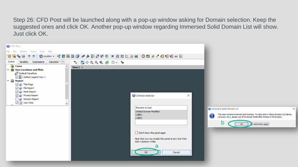
Step 26: CFD Post will be launched along with a pop-up window asking for Domain selection. Keep the
suggested ones and click OK. Another pop-up window regarding Immersed Solid Domain List will show.
Just click OK.
a
b

Step 27: Now insert Surface Group by click on the Location and then on Surface Group. Select All
Immersed Solids in Domains and for locations select LOBE1 Default and LOBE2 Default and click OK.
Click Apply. Lobes will be visible as shown in the image on the right.
a
b
c
d
e
f
g

Step 28: Now insert a plane by clicking on the Location and then on Plane. Under Geometry tab set a
value of 0.005 for Z for Definition. Under Color tab Select variable for Mode and select Pressure as
Variable. Click Apply to finalize.
a
b
c
d
e
f

Now you should see a plane showing pressure fields

Step 29: Now insert velocity vector by clicking on the vector tab and OK on the Insert Vector pop-up
window. For Locations select Plane 1, Equally Spaced for Sampling and 900 for # of Points. Click on
Color tab. Select Constant for Mode. For Color choose white color. Click on Symbol tab and set the
Symbol Size to 1.0. Select Normalize Symbols. Finally click Apply.
a
b
c
d
e
f

Now you should see a plane showing velocity vectors along with pressure field

Step 30: Uncheck Plane 1 and Vector 1 in the Outline tree.
Now insert a second plane by clicking on the Location and then on Plane.
Under Geometry tab set a value of 0.005 for Z for Definition. Under Color tab
Select variable for Mode and select Velocity as Variable. Click Apply.
c
d
e
f
g
h
a
b

Now you should see a plane showing velocity fields
Simulation files for this tutorial can be downloaded for free from FetchCFD at: http://fetchcfd.com/view-project/732

Extra Notes
Lobe Pumps
Used in industries e.g. chemical, food, etc. due to
sanitary qualities, high efficiency, corrosion
resistance etc.
Immersed Body Solver
Moving solid without mesh deformation. Fluid mesh is generated that
covers both the solid and fluid regions.
SAS Model
Considers von Karman length-scale into the turbulence equation.
Delivers LES-like behavior.

That’s All,
Thanks
Reference/Source:
- Original lobe pump CAD model by Nicolas Marc: https://grabcad.com/library/lobe-pump-1
- Further lobe pump credits: https://commons.wikimedia.org/wiki/File:Roots_blower_-_2_lobes.svg?uselang=fr http://www.mekanizmalar.com/menu-pump.html
- Lobe Pump Mesh for CFD Simulation: http://fetchcfd.com/view-project/731
- Lobe Pump CFD Simulation: http://fetchcfd.com/view-project/732
- ANSYS Inc. 2017: http://www.ansys.com/
- Document Layout: https://docs.google.com/presentation
External Gear Pump Simulation using ANSYS CFX
Similar Project


![[Ansys] CFX-Mesh Tutorials](https://img.dokumen.tips/doc/110x75/550134884a7959ac638b4c7f/ansys-cfx-mesh-tutorials.jpg)