Embed Size (px)
Citation preview

VALIDATION OF CONTACT SIMULATION FOR ROBOTIC MANIPULATION IN SPACE
Arthur Wahl, Georgij Grinshpun, and Juergen Rossmann
Institute for Man-Machine Interaction, RWTH Aachen UniversityAhornstr. 55, D-52074 Aachen, Germany
{wahl, grinshpun, rossmann}@mmi.rwth-aachen.de
ABSTRACT
The detachment as well as reattachment of satellite com-ponents during a reconfiguration or repair process repre-sents a challenging task, since the establishment of a sta-ble contact between the connection interfaces of the satel-lite’s components and the robot manipulators of a servicersatellite is required. To asses such scenarios, we proposethe application of a simulation driven approach. Our ap-proach builds upon a Virtual Testbed for space environ-ments and presents a novel collision detection algorithmtailored to connection interfaces composed of centeringpins and holes. The algorithm performs contact manifoldand penetration depth computation in real-time. To vali-date our approach, docking scenarios between a centeringpin and an interface’s hole were performed within a ded-icated setup in a series of reference experiments with realhardware and robots.
Key words: Collision Detection; Contact Manifold &Penetration Depth Computation; Peg-In-Hole; HardwareExperiments; Virtual Testbeds; Simulation Frameworks.
1. INTRODUCTION
Today’s satellites are monolithic systems, whose lifetimeis often determined by the lifetime of their critical com-ponents. Without any feasible way of maintenance orrepair, malfunctioning components can lead to an earlytermination of a satellite’s mission period. At the end ofits lifetime, a satellite becomes space debris that may en-danger other satellites. The concept of modular satellitesas presented in the project iBOSS (intelligent BuildingBlocks for On-Orbit Satellite Servicing, [11]) is aiming tocontribute to the reduction of space debris by extendingthe lifespan of satellites through easier maintainability oftheir components. A modular design simplifies accessto malfunctioning components and enables their replace-ment through servicer satellites during on-orbit-satelliteservicing missions [2], see Figure 1.Detachment as well as reattachment of components dur-ing reconfiguration or repair processes represent a chal-lenging task, since the establishment of a stable contactbetween the connection interfaces of a satellite’s compo-nent and the robot manipulators of a servicer satellite isrequired. Therefore, we propose the application of Vir-tual Testbeds [7], [9] to assess such scenarios. Virtual
Figure 1. Simulation of an on-orbit satellite servicingmission in Virtual Robotic Testbed for space environ-ments [7]: A servicer satellite (l.h.s.) is docked to amodular satellite (r.h.s.) and replaces a malfunctioningcomponent (iBOSS concept [11]).
Testbeds enable analysis, as well as verification of al-gorithms regarding reconfiguration, handling, and place-ment of a satellites components by means of simulation.Establishing a stable contact is essential for the success-ful completion of any reconfiguration or repair task. Thefirst contact between a servicer’s robot manipulator and atarget component should establish a stable contact and isusually implemented by multiple centering pins [2]), seeFigure 2. These pins enter in contact with the target’s me-chanical interface and assure the self-centering of the ma-nipulator. A robot manipulator detects occurring impactsbetween the centering pins and the interface. The manip-ulator’s controller reacts according to the arising forcesand allows the centering pins to slide into the interfacesdocking holes. In general, the process can be modeled asa Peg-In-Hole situation, which is a well-studied but stillchallenging task in robotic applications [12], [10], [6].Therefore we focused on Peg-In-Hole scenarios with re-spect to the goal of docking a servicer’s robot manipulatorto a mechanical interface of a modular satellite’s compo-nent by developing a simulation environment that cap-tures the dynamic behavior between centering pins anddocking holes during contact. Our approach builds upon
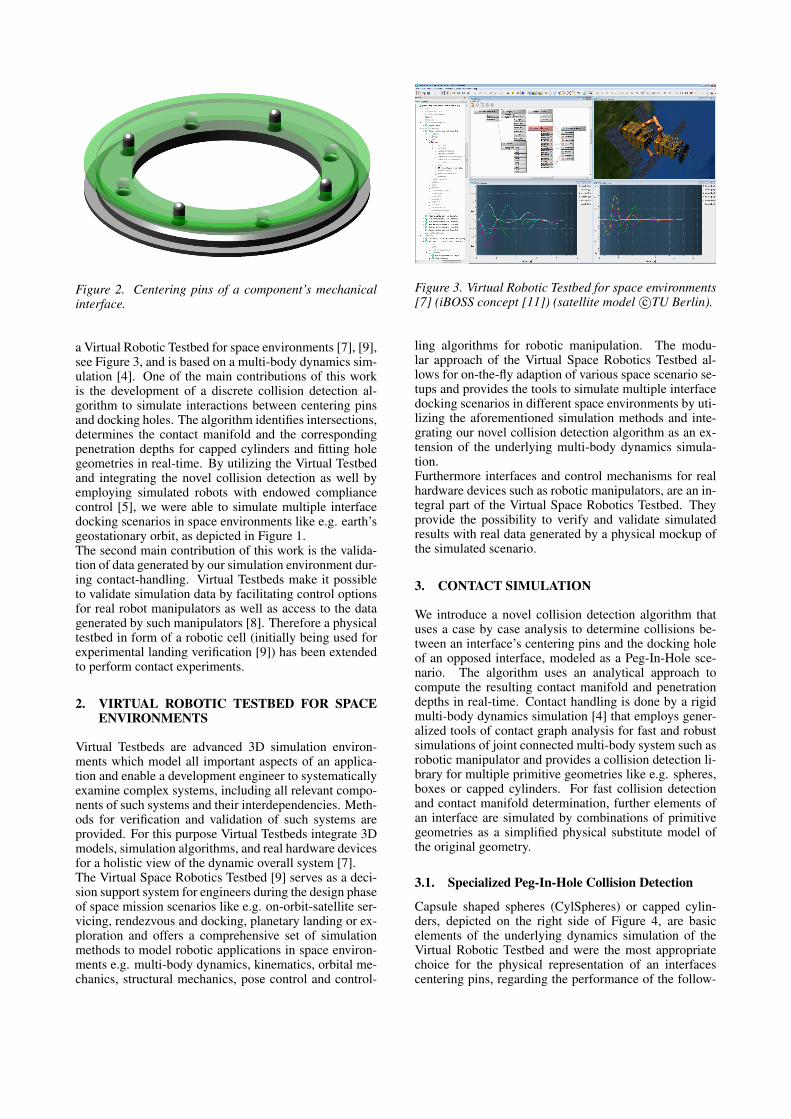
Figure 2. Centering pins of a component’s mechanicalinterface.
a Virtual Robotic Testbed for space environments [7], [9],see Figure 3, and is based on a multi-body dynamics sim-ulation [4]. One of the main contributions of this workis the development of a discrete collision detection al-gorithm to simulate interactions between centering pinsand docking holes. The algorithm identifies intersections,determines the contact manifold and the correspondingpenetration depths for capped cylinders and fitting holegeometries in real-time. By utilizing the Virtual Testbedand integrating the novel collision detection as well byemploying simulated robots with endowed compliancecontrol [5], we were able to simulate multiple interfacedocking scenarios in space environments like e.g. earth’sgeostationary orbit, as depicted in Figure 1.The second main contribution of this work is the valida-tion of data generated by our simulation environment dur-ing contact-handling. Virtual Testbeds make it possibleto validate simulation data by facilitating control optionsfor real robot manipulators as well as access to the datagenerated by such manipulators [8]. Therefore a physicaltestbed in form of a robotic cell (initially being used forexperimental landing verification [9]) has been extendedto perform contact experiments.
2. VIRTUAL ROBOTIC TESTBED FOR SPACEENVIRONMENTS
Virtual Testbeds are advanced 3D simulation environ-ments which model all important aspects of an applica-tion and enable a development engineer to systematicallyexamine complex systems, including all relevant compo-nents of such systems and their interdependencies. Meth-ods for verification and validation of such systems areprovided. For this purpose Virtual Testbeds integrate 3Dmodels, simulation algorithms, and real hardware devicesfor a holistic view of the dynamic overall system [7].The Virtual Space Robotics Testbed [9] serves as a deci-sion support system for engineers during the design phaseof space mission scenarios like e.g. on-orbit-satellite ser-vicing, rendezvous and docking, planetary landing or ex-ploration and offers a comprehensive set of simulationmethods to model robotic applications in space environ-ments e.g. multi-body dynamics, kinematics, orbital me-chanics, structural mechanics, pose control and control-
Figure 3. Virtual Robotic Testbed for space environments[7] (iBOSS concept [11]) (satellite model c©TU Berlin).
ling algorithms for robotic manipulation. The modu-lar approach of the Virtual Space Robotics Testbed al-lows for on-the-fly adaption of various space scenario se-tups and provides the tools to simulate multiple interfacedocking scenarios in different space environments by uti-lizing the aforementioned simulation methods and inte-grating our novel collision detection algorithm as an ex-tension of the underlying multi-body dynamics simula-tion.Furthermore interfaces and control mechanisms for realhardware devices such as robotic manipulators, are an in-tegral part of the Virtual Space Robotics Testbed. Theyprovide the possibility to verify and validate simulatedresults with real data generated by a physical mockup ofthe simulated scenario.
3. CONTACT SIMULATION
We introduce a novel collision detection algorithm thatuses a case by case analysis to determine collisions be-tween an interface’s centering pins and the docking holeof an opposed interface, modeled as a Peg-In-Hole sce-nario. The algorithm uses an analytical approach tocompute the resulting contact manifold and penetrationdepths in real-time. Contact handling is done by a rigidmulti-body dynamics simulation [4] that employs gener-alized tools of contact graph analysis for fast and robustsimulations of joint connected multi-body system such asrobotic manipulator and provides a collision detection li-brary for multiple primitive geometries like e.g. spheres,boxes or capped cylinders. For fast collision detectionand contact manifold determination, further elements ofan interface are simulated by combinations of primitivegeometries as a simplified physical substitute model ofthe original geometry.
3.1. Specialized Peg-In-Hole Collision Detection
Capsule shaped spheres (CylSpheres) or capped cylin-ders, depicted on the right side of Figure 4, are basicelements of the underlying dynamics simulation of theVirtual Robotic Testbed and were the most appropriatechoice for the physical representation of an interfacescentering pins, regarding the performance of the follow-
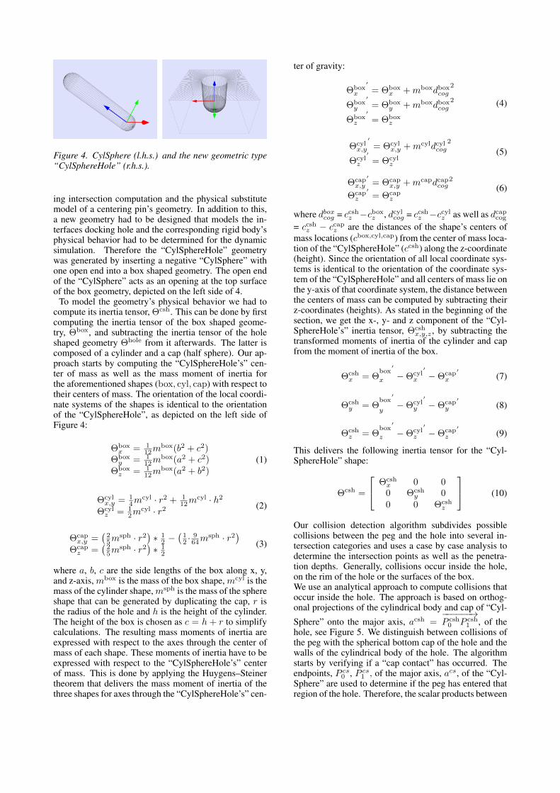
Figure 4. CylSphere (l.h.s.) and the new geometric type“CylSphereHole” (r.h.s.).
ing intersection computation and the physical substitutemodel of a centering pin’s geometry. In addition to this,a new geometry had to be designed that models the in-terfaces docking hole and the corresponding rigid body’sphysical behavior had to be determined for the dynamicsimulation. Therefore the “CylSphereHole” geometrywas generated by inserting a negative “CylSphere” withone open end into a box shaped geometry. The open endof the “CylSphere” acts as an opening at the top surfaceof the box geometry, depicted on the left side of 4.
To model the geometry’s physical behavior we had tocompute its inertia tensor, Θcsh. This can be done by firstcomputing the inertia tensor of the box shaped geome-try, Θbox, and subtracting the inertia tensor of the holeshaped geometry Θhole from it afterwards. The latter iscomposed of a cylinder and a cap (half sphere). Our ap-proach starts by computing the “CylSphereHole’s” cen-ter of mass as well as the mass moment of inertia forthe aforementioned shapes (box, cyl, cap) with respect totheir centers of mass. The orientation of the local coordi-nate systems of the shapes is identical to the orientationof the “CylSphereHole”, as depicted on the left side ofFigure 4:
Θboxx = 1
12mbox(b2 + c2)
Θboxy = 1
12mbox(a2 + c2)
Θboxz = 1
12mbox(a2 + b2)
(1)
Θcylx,y = 1
4mcyl · r2 + 1
12mcyl · h2
Θcylz = 1
2mcyl · r2 (2)
Θcapx,y =
(25m
sph · r2)∗ 1
2 −(12 ·
964m
sph · r2)
Θcapz =
(25m
sph · r2)∗ 1
2
(3)
where a, b, c are the side lengths of the box along x, y,and z-axis, mbox is the mass of the box shape, mcyl is themass of the cylinder shape, msph is the mass of the sphereshape that can be generated by duplicating the cap, r isthe radius of the hole and h is the height of the cylinder.The height of the box is chosen as c = h + r to simplifycalculations. The resulting mass moments of inertia areexpressed with respect to the axes through the center ofmass of each shape. These moments of inertia have to beexpressed with respect to the “CylSphereHole’s” centerof mass. This is done by applying the Huygens–Steinertheorem that delivers the mass moment of inertia of thethree shapes for axes through the “CylSphereHole’s” cen-
ter of gravity:
Θboxx
′
= Θboxx + mboxdboxcog
2
Θboxy
′
= Θboxy + mboxdboxcog
2
Θboxz
′
= Θboxz
(4)
Θcylx,y
′
= Θcylx,y + mcyldcylcog
2
Θcylz
′
= Θcylz
(5)
Θcapx,y
′= Θcap
x,y + mcapdcapcog2
Θcapz
′= Θcap
z
(6)
where dboxcog = ccshz −cboxz , dcylcog = ccshz −ccylz as well as dcapcog
= ccshz − ccapz are the distances of the shape’s centers ofmass locations (cbox,cyl,cap) from the center of mass loca-tion of the “CylSphereHole” (ccsh) along the z-coordinate(height). Since the orientation of all local coordinate sys-tems is identical to the orientation of the coordinate sys-tem of the “CylSphereHole” and all centers of mass lie onthe y-axis of that coordinate system, the distance betweenthe centers of mass can be computed by subtracting theirz-coordinates (heights). As stated in the beginning of thesection, we get the x-, y- and z component of the “Cyl-SphereHole’s” inertia tensor, Θcsh
x,y,z , by subtracting thetransformed moments of inertia of the cylinder and capfrom the moment of inertia of the box.
Θcshx = Θ
box
x
′
−Θcylx
′
−Θcapx
′(7)
Θcshy = Θ
box
y
′
−Θcyly
′
−Θcapy
′(8)
Θcshz = Θ
box
z
′
−Θcylz
′
−Θcapz
′(9)
This delivers the following inertia tensor for the “Cyl-SphereHole” shape:
Θcsh =
Θcshx 0 00 Θcsh
y 00 0 Θcsh
z
(10)
Our collision detection algorithm subdivides possiblecollisions between the peg and the hole into several in-tersection categories and uses a case by case analysis todetermine the intersection points as well as the penetra-tion depths. Generally, collisions occur inside the hole,on the rim of the hole or the surfaces of the box.We use an analytical approach to compute collisions thatoccur inside the hole. The approach is based on orthog-onal projections of the cylindrical body and cap of “Cyl-
Sphere” onto the major axis, acsh =−−−−−−→P csh0 P csh
1 , of thehole, see Figure 5. We distinguish between collisions ofthe peg with the spherical bottom cap of the hole and thewalls of the cylindrical body of the hole. The algorithmstarts by verifying if a “cap contact” has occurred. Theendpoints, P cs
0 , P cs1 , of the major axis, acs, of the “Cyl-
Sphere” are used to determine if the peg has entered thatregion of the hole. Therefore, the scalar products between
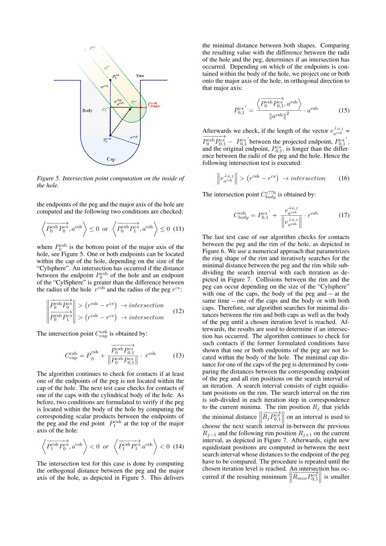
Figure 5. Intersection point computation on the inside ofthe hole.
the endpoints of the peg and the major axis of the hole arecomputed and the following two conditions are checked:⟨−−−−−→
P csh0 P cs
0 , acsh⟩≤ 0 or
⟨−−−−−→P csh0 P cs
1 , acsh⟩≤ 0 (11)
where P csh0 is the bottom point of the major axis of the
hole, see Figure 5. One or both endpoints can be locatedwithin the cap of the hole, depending on the size of the“Cylsphere”. An intersection has occurred if the distancebetween the endpoint P csh
0 of the hole and an endpointof the “CylSphere” is greater than the difference betweenthe radius of the hole rcsh and the radius of the peg rcs:∥∥∥−−−−−→P csh
0 P cs0
∥∥∥ >(rcsh − rcs
)→ intersection∥∥∥−−−−−→P csh
0 P cs1
∥∥∥ >(rcsh − rcs
)→ intersection
(12)
The intersection point Ccshcap is obtained by:
Ccshcap = P
csh
0+
−−−−−→P csh0 P cs
0,1∥∥P csh0 P cs
0,1
∥∥ · rcsh (13)
The algorithm continues to check for contacts if at leastone of the endpoints of the peg is not located within thecap of the hole. The next test case checks for contacts ofone of the caps with the cylindrical body of the hole. Asbefore, two conditions are formulated to verify if the pegis located within the body of the hole by computing thecorresponding scalar products between the endpoints ofthe peg and the end point P csh
1 at the top of the majoraxis of the hole:⟨−−−−−→
P csh1 P cs
0 , acsh⟩
< 0 or
⟨−−−−−→P csh1 P cs
1 acsh⟩
< 0 (14)
The intersection test for this case is done by computingthe orthogonal distance between the peg and the majoraxis of the hole, as depicted in Figure 5. This delivers
the minimal distance between both shapes. Comparingthe resulting value with the difference between the radiiof the hole and the peg, determines if an intersection hasoccurred. Depending on which of the endpoints is con-tained within the body of the hole, we project one or bothonto the major axis of the hole, in orthogonal direction tothat major axis:
P cs0,1
′=
⟨−−−−−→P csh0 P cs
0,1, acsh⟩
‖acsh‖2· acsh (15)
Afterwards we check, if the length of the vector v⊥0,1
acsh =−−−−−→P csh0 P cs
0,1 − P cs0,1
′between the projected endpoint, P cs
0,1
′,
and the original endpoint, P cs0,1, is longer than the differ-
ence between the radii of the peg and the hole. Hence thefollowing intersection test is executed:∥∥∥v⊥0,1
acsh
∥∥∥ >(rcsh − rcs
)→ intersection (16)
The intersection point Cc??hbody is obtained by:
Ccshbody = P cs
0,1
′+
v⊥0,1
acsh∥∥∥v⊥0,1
acsh
∥∥∥ · rcsh (17)
The last test case of our algorithm checks for contactsbetween the peg and the rim of the hole, as depicted inFigure 6. We use a numerical approach that parametrizesthe ring shape of the rim and iteratively searches for theminimal distance between the peg and the rim while sub-dividing the search interval with each iteration as de-picted in Figure 7. Collisions between the rim and thepeg can occur depending on the size of the “Cylsphere”with one of the caps, the body of the peg and – at thesame time – one of the caps and the body or with bothcaps. Therefore, our algorithm searches for minimal dis-tances between the rim and both caps as well as the bodyof the peg until a chosen iteration level is reached. Af-terwards, the results are used to determine if an intersec-tion has occurred. The algorithm continues to check forsuch contacts if the former formulated conditions haveshown that one or both endpoints of the peg are not lo-cated within the body of the hole. The minimal cap dis-tance for one of the caps of the peg is determined by com-paring the distances between the corresponding endpointof the peg and all rim positions on the search interval ofan iteration. A search interval consists of eight equidis-tant positions on the rim. The search interval on the rimis sub-divided in each iteration step in correspondenceto the current minima. The rim position Rj that yields
the minimal distance∥∥∥−−−−→RjP
cs0,1
∥∥∥ on an interval is used tochoose the next search interval in-between the previousRj−1 and the following rim position Rj+1 on the currentinterval, as depicted in Figure 7. Afterwards, eight newequidistant positions are computed in-between the nextsearch interval whose distances to the endpoint of the peghave to be compared. The procedure is repeated until thechosen iteration level is reached. An intersection has oc-curred if the resulting minimum
∥∥∥−−−−−−→RminPcs0,1
∥∥∥ is smaller
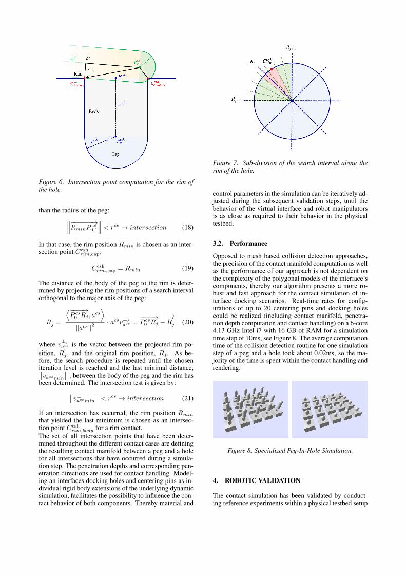
Figure 6. Intersection point computation for the rim ofthe hole.
than the radius of the peg:∥∥∥−−−−−−→RminPcs0,1
∥∥∥ < rcs → intersection (18)
In that case, the rim position Rmin is chosen as an inter-section point Ccsh
rim,cap:
Ccshrim,cap = Rmin (19)
The distance of the body of the peg to the rim is deter-mined by projecting the rim positions of a search intervalorthogonal to the major axis of the peg:
R′
j =
⟨−−−−→P cs0 Rj , a
cs⟩
‖acs‖2· acsv⊥j
acs =−−−−→P cs0 Rj −
−→R
′
j (20)
where v⊥j
acs is the vector between the projected rim po-sition, R
′
j , and the original rim position, Rj . As be-fore, the search procedure is repeated until the choseniteration level is reached and the last minimal distance,∥∥v⊥acsmin
∥∥ , between the body of the peg and the rim hasbeen determined. The intersection test is given by:∥∥v⊥acsmin
∥∥ < rcs → intersection (21)
If an intersection has occurred, the rim position Rmin
that yielded the last minimum is chosen as an intersec-tion point Ccsh
rim,body for a rim contact.The set of all intersection points that have been deter-mined throughout the different contact cases are definingthe resulting contact manifold between a peg and a holefor all intersections that have occurred during a simula-tion step. The penetration depths and corresponding pen-etration directions are used for contact handling. Model-ing an interfaces docking holes and centering pins as in-dividual rigid body extensions of the underlying dynamicsimulation, facilitates the possibility to influence the con-tact behavior of both components. Thereby material and
Figure 7. Sub-division of the search interval along therim of the hole.
control parameters in the simulation can be iteratively ad-justed during the subsequent validation steps, until thebehavior of the virtual interface and robot manipulatorsis as close as required to their behavior in the physicaltestbed.
3.2. Performance
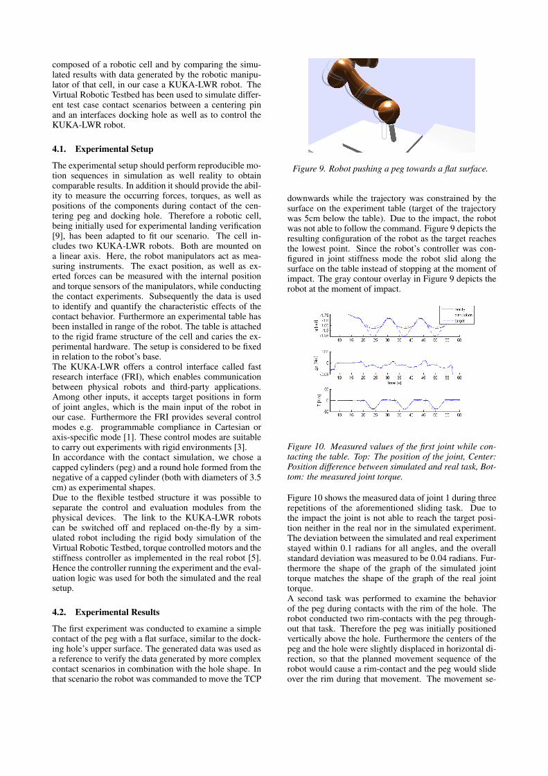
Opposed to mesh based collision detection approaches,the precision of the contact manifold computation as wellas the performance of our approach is not dependent onthe complexity of the polygonal models of the interface’scomponents, thereby our algorithm presents a more ro-bust and fast approach for the contact simulation of in-terface docking scenarios. Real-time rates for config-urations of up to 20 centering pins and docking holescould be realized (including contact manifold, penetra-tion depth computation and contact handling) on a 6-core4.13 GHz Intel i7 with 16 GB of RAM for a simulationtime step of 10ms, see Figure 8. The average computationtime of the collision detection routine for one simulationstep of a peg and a hole took about 0.02ms, so the ma-jority of the time is spent within the contact handling andrendering.
Figure 8. Specialized Peg-In-Hole Simulation.
4. ROBOTIC VALIDATION
The contact simulation has been validated by conduct-ing reference experiments within a physical testbed setup
composed of a robotic cell and by comparing the simu-lated results with data generated by the robotic manipu-lator of that cell, in our case a KUKA-LWR robot. TheVirtual Robotic Testbed has been used to simulate differ-ent test case contact scenarios between a centering pinand an interfaces docking hole as well as to control theKUKA-LWR robot.
4.1. Experimental Setup
The experimental setup should perform reproducible mo-tion sequences in simulation as well reality to obtaincomparable results. In addition it should provide the abil-ity to measure the occurring forces, torques, as well aspositions of the components during contact of the cen-tering peg and docking hole. Therefore a robotic cell,being initially used for experimental landing verification[9], has been adapted to fit our scenario. The cell in-cludes two KUKA-LWR robots. Both are mounted ona linear axis. Here, the robot manipulators act as mea-suring instruments. The exact position, as well as ex-erted forces can be measured with the internal positionand torque sensors of the manipulators, while conductingthe contact experiments. Subsequently the data is usedto identify and quantify the characteristic effects of thecontact behavior. Furthermore an experimental table hasbeen installed in range of the robot. The table is attachedto the rigid frame structure of the cell and caries the ex-perimental hardware. The setup is considered to be fixedin relation to the robot’s base.The KUKA-LWR offers a control interface called fastresearch interface (FRI), which enables communicationbetween physical robots and third-party applications.Among other inputs, it accepts target positions in formof joint angles, which is the main input of the robot inour case. Furthermore the FRI provides several controlmodes e.g. programmable compliance in Cartesian oraxis-specific mode [1]. These control modes are suitableto carry out experiments with rigid environments [3].In accordance with the contact simulation, we chose acapped cylinders (peg) and a round hole formed from thenegative of a capped cylinder (both with diameters of 3.5cm) as experimental shapes.Due to the flexible testbed structure it was possible toseparate the control and evaluation modules from thephysical devices. The link to the KUKA-LWR robotscan be switched off and replaced on-the-fly by a sim-ulated robot including the rigid body simulation of theVirtual Robotic Testbed, torque controlled motors and thestiffness controller as implemented in the real robot [5].Hence the controller running the experiment and the eval-uation logic was used for both the simulated and the realsetup.
4.2. Experimental Results
The first experiment was conducted to examine a simplecontact of the peg with a flat surface, similar to the dock-ing hole’s upper surface. The generated data was used asa reference to verify the data generated by more complexcontact scenarios in combination with the hole shape. Inthat scenario the robot was commanded to move the TCP
Figure 9. Robot pushing a peg towards a flat surface.
downwards while the trajectory was constrained by thesurface on the experiment table (target of the trajectorywas 5cm below the table). Due to the impact, the robotwas not able to follow the command. Figure 9 depicts theresulting configuration of the robot as the target reachesthe lowest point. Since the robot’s controller was con-figured in joint stiffness mode the robot slid along thesurface on the table instead of stopping at the moment ofimpact. The gray contour overlay in Figure 9 depicts therobot at the moment of impact.
Figure 10. Measured values of the first joint while con-tacting the table. Top: The position of the joint, Center:Position difference between simulated and real task, Bot-tom: the measured joint torque.
Figure 10 shows the measured data of joint 1 during threerepetitions of the aforementioned sliding task. Due tothe impact the joint is not able to reach the target posi-tion neither in the real nor in the simulated experiment.The deviation between the simulated and real experimentstayed within 0.1 radians for all angles, and the overallstandard deviation was measured to be 0.04 radians. Fur-thermore the shape of the graph of the simulated jointtorque matches the shape of the graph of the real jointtorque.A second task was performed to examine the behaviorof the peg during contacts with the rim of the hole. Therobot conducted two rim-contacts with the peg through-out that task. Therefore the peg was initially positionedvertically above the hole. Furthermore the centers of thepeg and the hole were slightly displaced in horizontal di-rection, so that the planned movement sequence of therobot would cause a rim-contact and the peg would slideover the rim during that movement. The movement se-
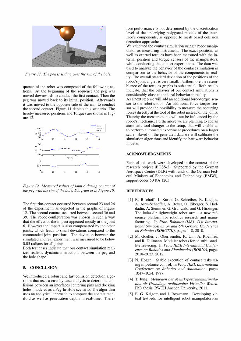
Figure 11. The peg is sliding over the rim of the hole.
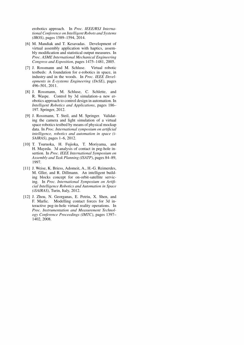
quence of the robot was composed of the following ac-tions. At the beginning of the sequence the peg wasmoved downwards to conduct the first contact. Then thepeg was moved back to its initial position. Afterwardsit was moved to the opposite side of the rim, to conductthe second contact. Figure 11 depicts this scenario. Thehereby measured positions and Torques are shown in Fig-ure 12.
Figure 12. Measured values of joint 6 during contact ofthe peg with the rim of the hole. Diagram as in Figure 10.
The first rim-contact occurred between second 23 and 26of the experiment, as depicted in the graphs of Figure12. The second contact occurred between second 36 and39. The robot configuration was chosen in such a waythat the effect of the impact appeared mostly at the joint6. However the impact is also compensated by the otherjoints, which leads to small deviations compared to thecommanded joint positions. The deviation between thesimulated and real experiment was measured to be below0.05 radians for all joints.Both test cases indicate that our contact simulation real-izes realistic dynamic interactions between the peg andthe hole shape.
5. CONCLUSION
We introduced a robust and fast collision detection algo-rithm that uses a case by case analysis to determine col-lisions between an interfaces centering pins and dockingholes, modeled as a Peg-In-Hole scenario. The algorithmuses an analytical approach to compute the contact man-ifold as well as penetration depths in real-time. There-
fore performance is not determined by the discretizationlevel of the underlying polygonal models of the inter-face’s components, as opposed to mesh based collisiondetection approaches.We validated the contact simulation using a robot manip-ulator as measuring instrument. The exact position, aswell as exerted torques have been measured with the in-ternal position and torque sensors of the manipulators,while conducting the contact experiments. The data wasused to analyze the behavior of the contact simulation incomparison to the behavior of the components in real-ity. The overall standard deviation of the positions of therobot’s joint angles is very small. Furthermore the resem-blance of the torques graphs is substantial. Both resultsindicate, that the behavior of our contact simulations isconsiderably close to the ideal behavior in reality.As a next step we will add an additional force-torque sen-sor to the robot’s tool. An additional force-torque sen-sor will provide the possibility to measure the occurringforces directly at the tool of the robot instead of the joints.Thereby the measurements will not be influenced by therobot’s mechanic. Furthermore we are planning to add anautomatic tool changer to the setup, that will enable usto perform automated experiment procedures on a largerscale. Based on the generated data we will calibrate thesimulation algorithms and identify the hardware behaviorin detail.
ACKNOWLEDGMENTS
Parts of this work were developed in the context of theresearch project iBOSS-2. Supported by the GermanAerospace Center (DLR) with funds of the German Fed-eral Ministry of Economics and Technology (BMWi),support codes 50 RA 1203.
REFERENCES
[1] R. Bischoff, J. Kurth, G. Schreiber, R. Koeppe,A. Albu-Schaeffer, A. Beyer, O. Eiberger, S. Had-dadin, A. Stemmer, G. Grunwald, and G. Hirzinger.The kuka-dlr lightweight robot arm - a new ref-erence platform for robotics research and manu-facturing. In Proc. Robotics (ISR), 41st Interna-tional Symposium on and 6th German Conferenceon Robotics (ROBOTIK), pages 1–8, 2010.
[2] M. Goeller, J. Oberlaender, K. Uhl, A. Roennau,and R. Dillmann. Modular robots for on-orbit satel-lite servicing. In Proc. IEEE International Confer-ence on Robotics and Biomimetics (ROBIO), pages2018–2023, 2012.
[3] N. Hogan. Stable execution of contact tasks us-ing impedance control. In Proc. IEEE InternationalConference on Robotics and Automation, pages1047–1054, 1987.
[4] T. Jung. Methoden der Mehrkrperdynamiksimula-tion als Grundlage realittsnaher Virtueller Welten.PhD thesis, RWTH Aachen University, 2011.
[5] E. G. Kaigom and J. Rossmann. Developing vir-tual testbeds for intelligent robot manipulators-an
erobotics approach. In Proc. IEEE/RSJ Interna-tional Conference on Intelligent Robots and Systems(IROS), pages 1589–1594, 2014.
[6] M. Mandiak and T. Kesavadas. Development ofvirtual assembly application with haptics, assem-bly modification and statistical output measures. InProc. ASME International Mechanical EngineeringCongress and Exposition, pages 1475–1481, 2005.
[7] J. Rossmann and M. Schluse. Virtual robotictestbeds: A foundation for e-robotics in space, inindustry-and in the woods. In Proc. IEEE Devel-opments in E-systems Engineering (DeSE), pages496–501, 2011.
[8] J. Rossmann, M. Schluse, C. Schlette, andR. Waspe. Control by 3d simulation–a new er-obotics approach to control design in automation. InIntelligent Robotics and Applications, pages 186–197. Springer, 2012.
[9] J. Rossmann, T. Steil, and M. Springer. Validat-ing the camera and light simulation of a virtualspace robotics testbed by means of physical mockupdata. In Proc. International symposium on artificialintelligence, robotics and automation in space (i-SAIRAS), pages 1–6, 2012.
[10] T. Tsuruoka, H. Fujioka, T. Moriyama, andH. Mayeda. 3d analysis of contact in peg-hole in-sertion. In Proc. IEEE International Symposium onAssembly and Task Planning (ISATP), pages 84–89,1997.
[11] J. Weise, K. Briess, Adomeit, A., H.-G. Reimerdes,M. Gller, and R. Dillmann. An intelligent build-ing blocks concept for on-orbit-satellite servic-ing. In Proc. International Symposium on Artifi-cial Intelligence Robotics and Automation in Space(iSAIRAS), Turin, Italy, 2012.
[12] J. Zhou, N. Georganas, E. Petriu, X. Shen, andF. Marlic. Modelling contact forces for 3d in-teractive peg-in-hole virtual reality operations. InProc. Instrumentation and Measurement Technol-ogy Conference Proceedings (IMTC), pages 1397–1402, 2008.