Embed Size (px)
Citation preview

BMHServo motorMotor manualV2.1, 03.2016
www.schneider-electric.com
0198
4411
1374
9, V
2.1,
03.
2016
The information provided in this documentation contains generaldescriptions and/or technical characteristics of the performance of theproducts contained herein. This documentation is not intended as asubstitute for and is not to be used for determining suitability or relia-bility of these products for specific user applications. It is the duty ofany such user or integrator to perform the appropriate and completerisk analysis, evaluation and testing of the products with respect to therelevant specific application or use thereof. Neither Schneider Electricnor any of its affiliates or subsidiaries shall be responsible or liable formisuse of the information contained herein. If you have any sugges-tions for improvements or amendments or have found errors in thispublication, please notify us.
No part of this document may be reproduced in any form or by anymeans, electronic or mechanical, including photocopying, withoutexpress written permission of Schneider Electric.
All pertinent state, regional, and local safety regulations must beobserved when installing and using this product. For reasons of safetyand to help ensure compliance with documented system data, onlythe manufacturer should perform repairs to components.
When devices are used for applications with technical safety require-ments, the relevant instructions must be followed.
Failure to use Schneider Electric software or approved software withour hardware products may result in injury, harm, or improper operat-ing results.
Failure to observe this information can result in injury or equipmentdamage.
© 2016 Schneider Electric. All rights reserved.
BMH
2 Servo motor
0198
4411
1374
9, V
2.1,
03.
2016

Table of contents
Table of contents 3
Safety Information 5
Hazard categories 5
Please note 6
Qualification of personnel 6
Intended use 6
Product Related Information 7
Terminology Derived from Standards 10
About the book 13
1 Introduction 15
1.1 Motor family 15
1.2 Options and accessories 15
1.3 Nameplate 16
1.4 Type code 19
2 Technical Data 21
2.1 General characteristics 21
2.2 Motor-specific data 252.2.1 BMH070 252.2.2 BMH100 272.2.3 BMH140 292.2.4 BMH190 312.2.5 BMH205 32
2.3 Dimensions 34
2.4 Shaft-specific data 402.4.1 Force for pressing on 402.4.2 Shaft load 41
2.5 Options 442.5.1 Encoder 442.5.2 Holding brake 462.5.3 Fan (BMH1904∙∙∙∙∙B only) 46
2.6 Conditions for UL 1004-1, UL 1004-6 and CSA 22.2 No. 100 46
2.7 Certifications 47
2.8 Declaration of conformity 48
3 Installation 49
3.1 Overview of procedure 51
BMH Table of contents
Servo motor 3
0198
4411
1374
9, V
2.1,
03.
2016

3.2 Electromagnetic compatibility (EMC) 51
3.3 Before mounting 54
3.4 Mounting the motor 603.4.1 Installation and connection of IP67 kit (accessory) 63
3.5 Electrical installation 653.5.1 Connectors and connector assignments 653.5.2 Power and encoder connection 703.5.3 Holding brake connection 77
3.6 Mounting and connecting the fan (BMH1904∙∙∙∙∙B only) 78
4 Commissioning 81
5 Diagnostics and troubleshooting 85
5.1 Mechanical problems 85
5.2 Electrical problems 85
6 Accessories and spare parts 87
6.1 IP67 Kit 87
6.2 Connectors 87
6.3 Motor cables 886.3.1 Motor cables 1.5 mm2 886.3.2 Motor cables 2.5 mm2 896.3.3 Motor cables 4 mm2 906.3.4 Motor cables 6 mm2 916.3.5 Motor cables 10 mm2 92
6.4 Encoder cables 93
7 Service, maintenance and disposal 95
7.1 Service address 95
7.2 Maintenance 95
7.3 Replacing the motor 98
7.4 Shipping, storage, disposal 99
Glossary 101
Terms and Abbreviations 101
Table of figures 103
Index 105
Table of contents BMH
4 Servo motor
0198
4411
1374
9, V
2.1,
03.
2016

Safety Information
Read these instructions carefully, and look at the equipment tobecome familiar with the device before trying to install, operate, serv-ice, or maintain it. The following special messages may appearthroughout this documentation or on the equipment to warn of poten-tial hazards or to call attention to information that clarifies or simplifiesa procedure.
The addition of this symbol to a DANGER safety label indi-cates that an electrical hazard exists, which will result inpersonal injury if the instructions are not followed.
This is the safety alert symbol. It is used to alert you topotential personal injury hazards. Obey all safety instruc-tions that follow this symbol to avoid possible injury ordeath.
Hazard categories
Safety instructions to the user are highlighted by safety alert symbolsin the manual. In addition, labels with symbols and/or instructions areattached to the product that alert you to potential hazards.
Four hazard categories exist depending on the criticality and nature ofthe hazard.
DANGERDANGER indicates a hazardous situation, which, if not avoided, willresult in death or serious injury.
WARNINGWARNING indicates a hazardous situation, which, if not avoided,could result in death, serious injury, or equipment damage.
CAUTIONCAUTION indicates a hazardous situation, which, if not avoided,could result in injury or equipment damage.
NOTICENOTICE indicates a hazardous situation, which, if not avoided, canresult in equipment damage.
BMH Safety Information
Servo motor 5
0198
4411
1374
9, V
2.1,
03.
2016

Please note
Electrical equipment should be installed, operated, serviced, andmaintained only by qualified personnel. No responsibility is assumedby Schneider Electric for any consequences arising out of the use ofthis material.
A qualified person is one who has skills and knowledge related to theconstruction and operation of electrical equipment and its installation,and has received safety training to recognize and avoid the hazardsinvolved.
Qualification of personnel
Only appropriately trained persons who are familiar with and under-stand the contents of this manual and all other pertinent product docu-mentation are authorized to work on and with this product.
In addition, these persons must have received safety training to recog-nize and avoid the hazards involved.
The qualified person must be able to detect possible hazards that mayarise from parameterization, modifying parameter values and gener-ally from mechanical, electrical, or electronic equipment.
The qualified person must be familiar with the standards, provisions,and regulations for the prevention of industrial accidents, which theymust observe when designing and implementing the system.
Intended use
This product is a motor and intended for industrial use according tothe present manual.
The product may only be used in compliance with all applicable safetyregulations and directives, the specified requirements and the techni-cal data.
Prior to using the product, you must perform a risk assessment in viewof the planned application. Based on the results, the appropriatesafety measures must be implemented.
Since the product is used as a component in an overall system, youmust ensure the safety of persons by means of the design of thisoverall system.
Operate the product only with the specified cables and accessories.Use only genuine accessories and spare parts.
Any use other than the use explicitly permitted is prohibited and canresult in hazards.
Electrical equipment should be installed, operated, serviced, andmaintained only by qualified personnel.
Safety Information BMH
6 Servo motor
0198
4411
1374
9, V
2.1,
03.
2016

Product Related Information
The use and application of the information contained herein requireexpertise in the design and programming of automated control sys-tems.
Only you, the user, machine builder or integrator, can be aware of allthe conditions and factors present during installation and setup, oper-ation, repair and maintenance of the machine or process.
You must also consider any applicable standards and/or regulationswith respect to grounding of all equipment. Verify compliance with anysafety information, different electrical requirements, and normativestandards that apply to your machine or process in the use of thisequipment.
Many components of the equipment, including the printed circuitboard, operate with mains voltage, or present transformed high cur-rents, and/or high voltages.
The motor itself generates voltage when the motor shaft is rotated.
BMH Safety Information
Servo motor 7
0198
4411
1374
9, V
2.1,
03.
2016

DANGERHAZARD DUE TO ELECTRIC SHOCK, EXPLOSION OR ARC FLASH
• Before performing work on the drive system:
- Disconnect all power from all equipment including connecteddevices prior to removing any covers or doors, or installing orremoving any accessories, hardware, cables, or wires.
- Place a "Do Not Turn On" or equivalent hazard label on allpower switches.
- Lock all power switches in the open (non-energized) position.- Wait 15 minutes to allow the DC bus capacitors to discharge.- Measure the voltage on the DC bus with a properly rated volt-
age sensing device as per the instructions in the presentdocument and verify that the voltage is less than 42.4 Vdc.
- Do not assume that the DC bus is voltage-free when the DCbus LED is off.
• Do not touch any connectors, contacts, terminals, unshieldedcomponents or printed circuit boards while, or if you suspect that,the equipment is under power.
• Use only electrically insulated tools.• Block the motor shaft to prevent rotation prior to performing any
type of work on the drive system.• Insulate both ends of unused conductors of the motor cable to
help prevent AC voltage from coupling to unused conductors inthe motor cable.
• Do not create a short-circuit across the DC bus terminals or theDC bus capacitors.
• Replace and secure all covers, accessories, hardware, cables,and wires and confirm that a proper ground connection existsbefore applying power to the unit.
• Use only the specified voltage when operating this equipment andany associated products.
Failure to follow these instructions will result in death or seri-ous injury.
This equipment has been designed to operate outside of any hazard-ous location. Only install this equipment in zones known to be free ofa hazardous atmosphere.
DANGERPOTENTIAL FOR EXPLOSION
Install and use this equipment in non-hazardous locations only.
Failure to follow these instructions will result in death or seri-ous injury.
NOTE: See the product manual of the servo drive for additional impor-tant safety information.
If the power stage is disabled unintentionally, for example as a resultof power outage, errors or functions, the motor is no longer deceler-ated in a controlled way. Overload, errors or incorrect use may cause
Safety Information BMH
8 Servo motor
0198
4411
1374
9, V
2.1,
03.
2016

the holding brake to no longer operate properly and may result in pre-mature wear.
WARNINGUNINTENDED EQUIPMENT OPERATION
• Verify that movements without braking effect cannot cause inju-ries or equipment damage.
• Verify the function of the holding brake at regular intervals.• Do not use the holding brake as a service brake.• Do not use the holding brake for safety-related purposes.
Failure to follow these instructions can result in death, seriousinjury, or equipment damage.
WARNINGLOSS OF CONTROL
• The designer of any control scheme must consider the potentialfailure modes of control paths and, for certain critical control func-tions, provide a means to achieve a safe state during and after apath failure. Examples of critical control functions are emergencystop and overtravel stop, power outage and restart.
• Separate or redundant control paths must be provided for criticalcontrol functions.
• System control paths may include communication links. Consider-ation must be given to the implications of unanticipated transmis-sion delays or failures of the link.
• Observe all accident prevention regulations and local safetyguidelines. 1)
• Each implementation of this equipment must be individually andthoroughly tested for proper operation before being placed intoservice.
Failure to follow these instructions can result in death, seriousinjury, or equipment damage.
1) For additional information, refer to NEMA ICS 1.1 (latest edition), “Safety Guidelinesfor the Application, Installation, and Maintenance of Solid State Control” and toNEMA ICS 7.1 (latest edition), “Safety Standards for Construction and Guide forSelection, Installation and Operation of Adjustable-Speed Drive Systems” or theirequivalent governing your particular location.
BMH Safety Information
Servo motor 9
0198
4411
1374
9, V
2.1,
03.
2016

Terminology Derived from Standards
The technical terms, terminology, symbols and the correspondingdescriptions in this manual, or that appear in or on the products them-selves, are generally derived from the terms or definitions of interna-tional standards.
In the area of functional safety systems, drives and general automa-tion, this may include, but is not limited to, terms such as "safety","safety function", "safe state", "fault", "fault reset", "malfunction", "fail-ure", "error", "error message", "dangerous", etc.
Among others, these standards include:
Standard DescriptionEN 61131-2:2007 Programmable controllers, part 2: Equipment requirements and tests.
ISO 13849-1:2008 Safety of machinery: Safety related parts of control systems.
General principles for design.
EN 61496-1:2013 Safety of machinery: Electro-sensitive protective equipment.
Part 1: General requirements and tests.
ISO 12100:2010 Safety of machinery - General principles for design - Risk assessment and risk reduction
EN 60204-1:2006 Safety of machinery - Electrical equipment of machines - Part 1: General requirements
EN 1088:2008
ISO 14119:2013
Safety of machinery - Interlocking devices associated with guards - Principles for designand selection
ISO 13850:2006 Safety of machinery - Emergency stop - Principles for design
EN/IEC 62061:2005 Safety of machinery - Functional safety of safety-related electrical, electronic, and elec-tronic programmable control systems
IEC 61508-1:2010 Functional safety of electrical/electronic/programmable electronic safety-related systems:General requirements.
IEC 61508-2:2010 Functional safety of electrical/electronic/programmable electronic safety-related systems:Requirements for electrical/electronic/programmable electronic safety-related systems.
IEC 61508-3:2010 Functional safety of electrical/electronic/programmable electronic safety-related systems:Software requirements.
IEC 61784-3:2008 Digital data communication for measurement and control: Functional safety field buses.
2006/42/EC Machinery Directive
2004/108/EC Electromagnetic Compatibility Directive
2006/95/EC Low Voltage Directive
In addition, terms used in the present document may tangentially beused as they are derived from other standards such as:
Standard DescriptionIEC 60034 series Rotating electrical machines
IEC 61800 series Adjustable speed electrical power drive systems
IEC 61158 series Digital data communications for measurement and control – Fieldbus for use in industrialcontrol systems
Finally, the term "zone of operation" may be used in conjunction withthe description of specific hazards, and is defined as it is for a "hazardzone" or "danger zone" in the Machinery Directive (2006/42/EC) andISO 12100:2010.
Safety Information BMH
10 Servo motor
0198
4411
1374
9, V
2.1,
03.
2016

NOTE: The aforementioned standards may or may not apply to thespecific products cited in the present documentation. For more infor-mation concerning the individual standards applicable to the productsdescribed herein, see the characteristics tables for those product ref-erences.
BMH Safety Information
Servo motor 11
0198
4411
1374
9, V
2.1,
03.
2016

Safety Information BMH
12 Servo motor
0198
4411
1374
9, V
2.1,
03.
2016

About the book
This manual is valid for BMH standard products. Chapter"1 Introduction" lists the type code for this product. The type codeallows you to identify whether your product is a standard product or acustomized version.
Source manuals The latest versions of the manuals can be downloaded from the Inter-net at:
http://www.schneider-electric.com
Work steps If work steps must be performed consecutively, this sequence of stepsis represented as follows:
■ Special prerequisites for the following work steps▶ Step 1◁ Specific response to this work step▶ Step 2
If a response to a work step is indicated, this allows you to verify thatthe work step has been performed correctly.
Unless otherwise stated, the individual steps must be performed in thespecified sequence.
Making work easier Information on making work easier is highlighted by this symbol:
Sections highlighted this way provide supplementary information onmaking work easier.
SI units Technical data are specified in SI units. Converted units are shown inparentheses behind the SI unit; they may be rounded.
Example:Minimum conductor cross section: 1.5 mm2 (AWG 14)
Glossary Explanations of special technical terms and abbreviations.
Index List of keywords with references to the corresponding page numbers.
BMH About the book
Servo motor 13
0198
4411
1374
9, V
2.1,
03.
2016

About the book BMH
14 Servo motor
0198
4411
1374
9, V
2.1,
03.
2016

1 Introduction
1.1 Motor family
The motors are AC synchronous servo motors with a very high powerdensity. A drive system consists of the AC synchronous servo motorand the appropriate drive. Maximum performance requires the motorand drive to be adapted to each other.
Characteristics The AC synchronous servo motors feature:
• High power density: the use of the latest magnetic materials andan optimized design result in motors with a shorter length at a com-parable torque.
• High peak torque: the peak torque can be up to four times the con-tinuous stall torque
1.2 Options and accessories
The motors are available with various options such as:
• Various encoder systems• Holding brake• Various shaft versions• Various degrees of protection• Various lengths• Various sizes• Various winding versions• Various connection versions• Fan cooling
The options can be found in the type code section on page 19.
For accessories see chapter "6 Accessories and spare parts", page87.
Gearboxes adapted to the motor can be found in the Lexium 32 prod-uct catalog.
BMH 1 Introduction
Servo motor 15
0198
4411
1374
9, V
2.1,
03.
2016

1.3 Nameplate
The nameplate contains the following data:
BMH070 and BMH100
BMH000000000000ID-No
0.00 Arms0.00 Nm
0000 rpm0.00 Arms000 Vrms
0000000000000
DOMSN
I0
UN
nmax
USC
Imax
M0 Made in Germany
Ubr 00VdcTh-CI F
QD
0.00 kW0000 rpm
PN nN
IEC 60034-1
3~
dd.mm.yyyy0000000000
IP50(65) Thermo-Mbr 00Nm Pbr 00W
21
5
78
6
9
111213143
4
19
18
10
1516
17
Figure 1: Nameplate BMH070 and BMH100
(1) Motor type, see type code(2) Identification number(3) Maximum nominal value of supply voltage(4) Maximum Current(5) Maximum speed of rotation(6) Continuous stall current(7) Continuous stall torque(8) Nominal power(9) Nominal speed of rotation(10) Number of motor phases(11) Thermal class(12) Degree of protection (housing without shaft bushing)(13) Temperature sensor(14) Holding brake data(15) Date of manufacture(16) Serial number(17) Applied standard(18) Country of manufacture, site(19) Barcode
1 Introduction BMH
16 Servo motor
0198
4411
1374
9, V
2.1,
03.
2016

BMH140 and BMH190
BMH000000000000ID-No
ArmsNm
rpmArmsVrms
0000000000000
DOMSN
I0
UN
nmax
USC
Imax
M0 Made in Germany
Ubr 00 VTh-CI F
QD
kWrpm
PN nN
IEC 60034-1
3~
dd.mm.yyyy0000000000
IP50(65) Thermo -Mbr 00 NmPbr 00 W
2
1
5
78
6
9
15
13
34
19
161718
Mass 00kg
10
20
0000.00
00000.000.000.00
0000
14
FanOption
WVDCUfan
Pfan 0000
21
1112
Figure 2: Nameplate BMH140 and BMH190
(1) Motor type, see type code(2) Identification number(3) Maximum nominal value of supply voltage(4) Maximum Current(5) Maximum speed of rotation(6) Continuous stall current(7) Continuous stall torque(8) Nominal power(9) Nominal speed of rotation(10) Fan data (BMH1904∙∙∙∙∙B only)(11) Number of motor phases(12) Thermal class(13) Degree of protection (housing without shaft bushing)(14) Temperature sensor(15) Holding brake data(16) Date of manufacture(17) Serial number(18) Mass of the motor(19) Applied standard(20) Country of manufacture, site(21) Barcode
BMH 1 Introduction
Servo motor 17
0198
4411
1374
9, V
2.1,
03.
2016

BMH205
BMH000000000000
ArmsNm
Vrms
DOM QDSN
I0
UN
USC
rpmnmax Imax M0
Th-CI F BL03kW
rpm
PN
nN
0 W0 Vdc
Pbr Ubr
0 NmMbr
RSdd.mm.yyyy0000000000
IP 50 (IP65)Thermo PTC
0.000.000000000
0.00
Mad
e in
Ger
man
y 0.000000
3
2
1
5
78
6
9
4
11
15
13
16
10
14
12
17
Arms
Figure 3: Nameplate BMH205
(1) Motor type, see type code(2) Continuous stall torque(3) Continuous stall current(4) Nominal speed of rotation(5) Maximum nominal value of supply voltage(6) Nominal power(7) Thermal class(8) Barcode(9) Country of manufacture, site(10) Maximum Current(11) Serial number(12) Date of manufacture(13) Hardware version(14) Maximum speed of rotation(15) Degree of protection (housing without shaft bushing)(16) Holding brake data(17) Temperature sensor
1 Introduction BMH
18 Servo motor
0198
4411
1374
9, V
2.1,
03.
2016

1.4 Type code
BMH 070 1 P 0 1 A 1 AProduct family BMH: Synchronous motor - medium moment of inertia
Size (housing) 070 = 70 mm flange100 = 100 mm flange140 = 140 mm flange190 = 190 mm flange205 = 205 mm flange
Length 1 = 1 stack2 = 2 stacks3 = 3 stacks4 = 4 stacks
Winding P = Optimized in terms of torque and speed of rotationT = Optimized in terms of high speed of rotation
Shaft and degree of protection 0 = Smooth shaft; degree of protection: shaft IP54 1), housing IP651 = Parallel key; degree of protection: shaft IP 54 1), housing IP 652 = Smooth shaft; degree of protection: shaft and housing IP65 1) 2) 3 = Parallel key; degree of protection: shaft and housing IP 65 1) 2)
Encoder system 1 = Absolute singleturn 128 Sin/Cos periods per revolution (SKS36)2 = Absolute multiturn 128 Sin/Cos periods per revolution (SKM36)6 = Absolute singleturn 16 Sin/Cos periods per revolution (SEK37)7 = Absolute multiturn 16 Sin/Cos periods per revolution (SEL37)
Holding brake A = Without holding brakeF = With holding brake
Connection version 1 = Straight connector2 = Angular connector 90°, can be rotated
Mechanical interface - mounting A = International IEC StandardB = International IEC standard and fan cooling1) In the case of mounting position IM V3 (drive shaft vertical, shaft end up), the motor only has degree of protection IP50.2) The maximum permissible speed of rotation is limited to 6000 rpm by the shaft sealing ring. Separate accessories allow you to
obtain degree of protection IP67. See chapter "6 Accessories and spare parts".
If you have questions concerning the type code, contact yourSchneider Electric sales office.
Designation customized version In the case of a customized version, position 8 of the type code is an"S". The subsequent number defines the customized version. Exam-ple: B∙∙∙∙∙∙S1234
Contact your machine vendor if you have questions concerning cus-tomized versions.
BMH 1 Introduction
Servo motor 19
0198
4411
1374
9, V
2.1,
03.
2016

1 Introduction BMH
20 Servo motor
0198
4411
1374
9, V
2.1,
03.
2016

2 Technical Data
This chapter contains information on the ambient conditions and onthe mechanical and electrical properties of the product family and theaccessories.
2.1 General characteristics
Motor type AC synchronous servo motor
Number of pairs of poles 5
Degree of protection motor housing IP65 As per IEC 60034-5
Degree of protection shaft bushingwithout shaft sealing ring
IP54 ) As per IEC 60034-5
Degree of protection shaft bushingwith shaft sealing ring
IP65 1) 2) As per IEC 60034-5
Degree of protection with IP67 kit IP67 ) As per IEC 60034-5
Degree of protection with fan IP20 As per IEC 60034-5
Thermal class F (155 C°) As per IEC 60034-1
Vibration grade A As per IEC 60034-14
Test voltage > 2400 Vac As per IEC 60034-1
Maximum permissible winding voltage BMH∙∙∙∙T 240 VacBMH∙∙∙∙P 480 Vac
Maximum voltage to ground 280 Vac
Perpendicularity normal class As per IEC 60072-1, DIN 42955
Housing color Black RAL 9005
Overvoltage category III As per IEC 61800-5-1
Protection class 3) I As per IEC 61140, EN 501781) With shaft sealing ring: the maximum speed of rotation is limited to 6000 rpm; shaft sealing ring with initial lubrication, if the seal
runs dry, this increases friction and reduces service life.2) In the case of mounting position IM V3 (drive shaft vertical, shaft end up), the motor only has degree of protection IP50. The degree
of protection only relates to the motor itself, not to mounted components such as, for example, a gearbox.3) The signals of the holding brake at CN1 and the signals at CN2 meet the PELV requirements.
Compatibility with foreign substan-ces
The motor has been tested for compatibility with many known sub-stances and with the latest available knowledge. Nonetheless, youmust perform a compatibility test prior to using a foreign substance.
Climatic environmental conditionstransportation and storage
The environment during transportation and storage must be dry andfree from dust.
The storage time is primarily limited by the service life of the lubricantsin the bearings. Do not store the product for more than 36 months andperiodically operate the motor.
If the holding brake is not used for an extended period of time, parts ofthe holding brake may corrode. Corrosion reduces the holding torque.See "Inspecting/breaking in the holding brake" in chapter"7 Service, maintenance and disposal".
BMH 2 Technical Data
Servo motor 21
0198
4411
1374
9, V
2.1,
03.
2016

Temperature °C(°F)
-40 ... 70(-40 ... 158)
Relative humidity (non-condens-ing)
% ≤75
Set of class combinations as perIEC 60721-3-2
IE 21
Climatic environmental conditionsoperation Ambient temperature 1) 2) (no
icing, non-condensing)°C(°F)
-20 ... 40(-4 ... 104)
Ambient temperature with currentderating of 1% per °C (per 1.8 °F)1) 2)
°C(°F)
40 ... 60(104 ... 140)
Relative humidity (non-condens-ing)
% 5 ... 85
Class as per IEC 60721-3-3 3K3, 3Z12, 3Z2, 3B2, 3C1, 3M6
Installation altitude 3) m(ft)
<1000(<3281)
Installation altitude with currentreduction of 1% per 100 m (328 ft)at altitudes of more than 1000 m(3281 ft) 3)
m(ft)
1000 ... 3000(3281 ... 9843)
1) Limit values with flanged motor (steel plate, height and width = 2.5 * motor flange,10 mm (0.39 in) thickness, centered hole).
2) BMH1904∙∙∙∙∙B: The fan, which is delivered with the motor, is required for opera-tion. For more information, refer to chapter"3.6 Mounting and connecting the fan (BMH1904∙∙∙∙∙B only)".
3) The installation altitude is defined in terms of altitude above mean sea level.
Vibration and shockBMH070 ... 190 Vibration, sinusoidal Type test with 10 runs as per
IEC 60068-2-60.15 mm (10 ... 60 Hz)20 m/s2 (60 ... 500 Hz)
Shock, semi-sinusoidal Type test with 3 shocks in each directionas per IEC 60068-2-27150 m/s2 (11 ms)
Vibration and shock BMH205Vibration, sinusoidal Type test with 10 runs as per
IEC 60068-2-60.35 mm (10 ... 60 Hz)50 m/s2 (60 ... 150 Hz)
Shock, semi-sinusoidal Type test with 3 shocks in each directionas per IEC 60068-2-27200 m/s2 (6 ms)
2 Technical Data BMH
22 Servo motor
0198
4411
1374
9, V
2.1,
03.
2016

Service lifeNominal bearing service life L10h 1) h 200001) Operating hours at a probability of failure of 10%
The service life of the motors when operated correctly is limited pri-marily by the service life of the rolling bearing.
The following operating conditions significantly reduce the service life:
• Installation altitude >1000 m (3281 ft) above mean sea level• Rotary movements exclusively within a fixed angle of <100°• Operation under vibration load >20 m/s2
• Allowing sealing rings to run dry• Contact of the seals with aggressive substances
Shaft sealing ring / degree of pro-tection
The motors can be equipped with an optional shaft sealing ring. Witha shaft sealing ring, they have degree of protection IP65. The shaftsealing ring limits the maximum speed of rotation to 6000 rpm.
Note the following:
• The shaft sealing ring is factory-pre-lubricated.• If the seals run dry, this increases friction and greatly reduces the
service life of the sealing rings.
Compressed air connection The compressed air generates a permanent overpressure inside themotor. This overpressure inside the motor is used to obtain degree ofprotection IP67.
Compressed air must also be available when the system is switchedoff, for example to maintain the required degree of protection duringcleaning work. When the compressed air is switched off, the degree ofprotection is decreased to IP65. The degree of protection only relatesto the motor itself, not to mounted components such as, for example,a gearbox.
Special compressed air must be used:
Nominal pressure bar(psi)
0.1 ... 0.3(1.45 ... 4.35)
Maximum air pressure bar(psi)
0.4(5.8)
Permissible humidity % 20 ... 30
Other properties of the com-pressed air
Free from dust, free from oil
BMH 2 Technical Data
Servo motor 23
0198
4411
1374
9, V
2.1,
03.
2016
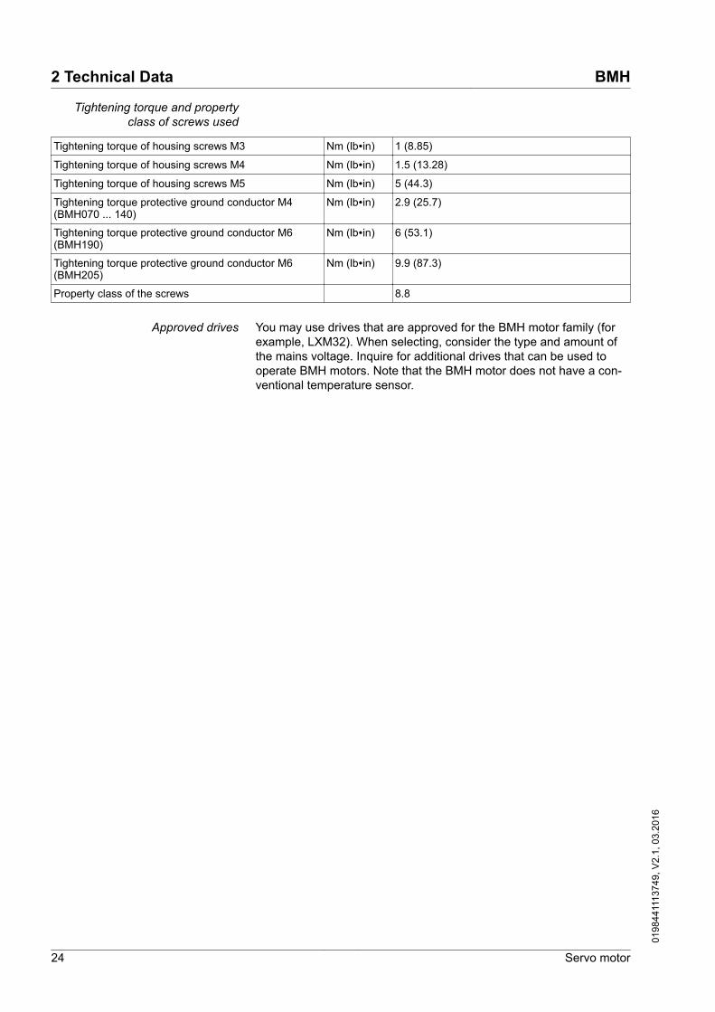
Tightening torque and propertyclass of screws used
Tightening torque of housing screws M3 Nm (lb∙in) 1 (8.85)
Tightening torque of housing screws M4 Nm (lb∙in) 1.5 (13.28)
Tightening torque of housing screws M5 Nm (lb∙in) 5 (44.3)
Tightening torque protective ground conductor M4(BMH070 ... 140)
Nm (lb∙in) 2.9 (25.7)
Tightening torque protective ground conductor M6(BMH190)
Nm (lb∙in) 6 (53.1)
Tightening torque protective ground conductor M6(BMH205)
Nm (lb∙in) 9.9 (87.3)
Property class of the screws 8.8
Approved drives You may use drives that are approved for the BMH motor family (forexample, LXM32). When selecting, consider the type and amount ofthe mains voltage. Inquire for additional drives that can be used tooperate BMH motors. Note that the BMH motor does not have a con-ventional temperature sensor.
2 Technical Data BMH
24 Servo motor
0198
4411
1374
9, V
2.1,
03.
2016

2.2 Motor-specific data
2.2.1 BMH070
BMH... 0701 0702 0703Winding P T P T P TTechnical data - generalContinuous stall torque M0 1) 2) Nm
(lb⋅in)1.40(12.39)
1.40(12.39)
2.48(21.95)
2.48(21.95)
3.40(30.09)
3.40(30.09)
Peak torque Mmax Nm(lb⋅in)
4.20(37.17)
4.20(37.17)
7.44(65.85)
7.44(65.85)
10.20(90.28)
10.20(90.28)
With supply voltage Un = 115 Vac 1)
Nominal speed of rotation nN rpm 1250 2500 1250 2500 1250 2000
Nominal torque MN Nm(lb⋅in)
1.38(12.21)
1.35(11.95)
2.37(20.98)
2.27(20.09)
3.18(28.15)
3.05(26.99)
Nominal current IN Arms 1.75 2.75 2.82 4.92 3.56 4.98
Nominal power PN kW 0.18 0.35 0.31 0.59 0.42 0.64
With supply voltage Un = 230 Vac 1)
Nominal speed of rotation nN rpm 3000 5000 3000 5000 2500 4000
Nominal torque MN Nm(lb⋅in)
1.34(11.86)
1.31(11.59)
2.23(19.74)
2.06(18.23)
2.96(26.20)
2.70(23.90)
Nominal current IN Arms 1.75 2.76 2.70 4.46 3.47 4.41
Nominal power PN kW 0.42 0.68 0.70 1.08 0.75 1.13
With supply voltage Un = 400 Vac 1)
Nominal speed of rotation nN rpm 5500 - 5500 - 5000 -
Nominal torque MN Nm(lb⋅in)
1.30(11.51)
- 2.01(17.79)
- 2.53(22.39)
-
Nominal current IN Arms 1.65 - 2.39 - 2.91 -
Nominal power PN kW 0.75 - 1.16 - 1.32 -
With supply voltage Un = 480 Vac 1)
Nominal speed of rotation nN rpm 7000 - 7000 - 6500 -
Nominal torque MN Nm(lb⋅in)
1.27(11.24)
- 1.89(16.73)
- 2.26(20.00)
-
Nominal current IN Arms 1.70 - 2.36 - 2.74 -
Nominal power PN kW 0.93 - 1.38 - 1.54 -1) Conditions for performance data: Mounted to steel plate (2.5 * flange dimension)2 area, 10 mm (0.39 in) thickness, centered hole.2) M0 = Continuous stall torque at 20 rpm and 100% duty cycle; at speeds of rotation of < 20 rpm the continuous stall torque is reduced
to 87%.
BMH 2 Technical Data
Servo motor 25
0198
4411
1374
9, V
2.1,
03.
2016

BMH... 0701 0702 0703Winding P T P T P TTechnical data - electricalMaximum current Imax Arms 5.97 9.56 9.65 17.64 12.57 17.84
Continuous stall current I0 Arms 1.78 2.85 2.94 5.38 3.91 5.55
Voltage constant kEu-v 1) Vrms 48.5 30.3 51.7 28.3 53.4 37.6
Torque constant kt 2) Nm/A 0.79 0.49 0.84 0.46 0.87 0.61
Winding resistance R20u-v Ω 8.61 3.47 3.79 1.15 2.54 1.24
Winding inductance Lqu-v mH 20.70 8.09 11.78 3.52 8.35 4.14
Winding inductance Ldu-v mH 20.70 8.09 11.78 3.52 8.35 4.14
Technical data - mechanicalMaximum speed of rotation nmax rpm 8000 8000 8000 8000 8000 8000
Rotor inertia without holding brake JM kgcm2 0.59 0.59 1.13 1.13 1.67 1.67
Rotor inertia with holding brake JM kgcm2 0.70 0.70 1.24 1.24 1.78 1.78
Mass without holding brake m kg 1.60 1.60 2.30 2.30 3.00 3.00
Mass with holding brake m kg 2.60 2.60 3.30 3.30 4.00 4.001) RMS value at 1000 rpm and 20 °C (68 °F).2) At n = 20 rpm and 100% duty cycle.
2 Technical Data BMH
26 Servo motor
0198
4411
1374
9, V
2.1,
03.
2016

2.2.2 BMH100
BMH... 1001 1002 1003Winding P T P T P TTechnical data - generalContinuous stall torque M0 1) 2) Nm
(lb⋅in)3.40(30.09)
3.40(30.09)
6.0(53.10)
6.1(53.99)
9.0(79.66)
7.5(66.38)
Peak torque Mmax Nm(lb⋅in)
10.20(90.28)
10.20(90.28)
18.00(159.31)
18.30(161.97)
27.00(238.97)
25.50(225.69)
With supply voltage Un = 115 Vac 1)
Nominal speed of rotation nN rpm 1000 1750 1000 1750 1000 1500
Nominal torque MN Nm(lb⋅in)
3.30(29.21)
3.20(28.32)
5.67(50.18)
5.75(50.89)
8.45(74.79)
7.88(69.74)
Nominal current IN Arms 3.07 4.85 4.81 8.26 7.30 9.40
Nominal power PN kW 0.35 0.58 0.59 1.05 0.88 1.24
With supply voltage Un = 230 Vac 1)
Nominal speed of rotation nN rpm 2000 4000 2000 3500 2500 3000
Nominal torque MN Nm(lb⋅in)
3.20(28.32)
2.90(25.67)
5.33(47.17)
4.80(42.48)
7.63(67.53)
7.25(64.17)
Nominal current IN Arms 2.99 4.50 4.58 7.00 6.70 8.80
Nominal power PN kW 0.67 1.20 1.12 1.76 2.00 2.28
With supply voltage Un = 400 Vac 1)
Nominal speed of rotation nN rpm 4000 - 4000 - 4000 -
Nominal torque MN Nm(lb⋅in)
3.00(26.55)
- 4.67(41.33)
- 6.00(53.10)
-
Nominal current IN Arms 2.83 - 4.10 - 5.30 -
Nominal power PN kW 1.26 - 1.95 - 2.50 -
With supply voltage Un = 480 Vac 1)
Nominal speed of rotation nN rpm 5000 - 5000 - 5000 -
Nominal torque MN Nm(lb⋅in)
2.90(25.67)
- 4.20(37.17)
- 4.78(42.31)
-
Nominal current IN Arms 2.75 - 3.73 - 4.30 -
Nominal power PN kW 1.52 - 2.27 - 2.50 -1) Conditions for performance data: Mounted to steel plate, 300 mm (11.8 in) * 300 mm (11.8 in) area, 20 mm (0.79 in) thickness, cen-
tered hole.2) M0 = Continuous stall torque at 20 rpm and 100% duty cycle; at speeds of rotation of < 20 rpm the continuous stall torque is reduced
to 87%.
BMH 2 Technical Data
Servo motor 27
0198
4411
1374
9, V
2.1,
03.
2016

BMH... 1001 1002 1003Winding P T P T P TTechnical data - electricalMaximum current Imax Arms 11.20 18.20 17.50 30.00 26.71 34.70
Continuous stall current I0 Arms 3.15 5.11 5.04 8.65 7.69 8.80
Voltage constant kEu-v 1) Vrms 70.30 43.00 78.00 46.10 77.95 56.00
Torque constant kt 2) Nm/A 1.09 0.67 1.19 0.71 1.17 0.85
Winding resistance R20u-v Ω 4.12 1.58 1.97 0.68 1.08 0.61
Winding inductance Lqu-v mH 14.90 5.44 8.24 2.84 5.23 2.71
Winding inductance Ldu-v mH 13.15 4.78 7.35 2.52 4.62 2.40
Technical data - mechanicalMaximum speed of rotation nmax rpm 6000 6000 6000 6000 6000 6000
Rotor inertia without holding brake JM kgcm2 3.19 3.19 6.28 6.28 9.37 9.37
Rotor inertia with holding brake JM kgcm2 3.68 3.68 6.77 6.77 10.30 10.30
Mass without holding brake m kg 3.34 3.34 4.92 4.92 6.50 6.50
Mass with holding brake m kg 4.80 4.80 6.38 6.38 8.15 8.151) RMS value at 1000 rpm and 20 °C (68 °F).2) At n = 20 rpm and 100% duty cycle.
2 Technical Data BMH
28 Servo motor
0198
4411
1374
9, V
2.1,
03.
2016

2.2.3 BMH140
BMH... 1401 1402 1403Winding P P PTechnical data - generalContinuous stall torque M0 1) 2) Nm
(lb⋅in)10.0(88.51)
16.8(148.7)
22.5(199.1)
Peak torque Mmax Nm(lb⋅in)
30.00(265.5)
50.40(446.1)
72.00(637.3)
With supply voltage Un = 115 Vac 1)
Nominal speed of rotation nN rpm 1000 1000 750
Nominal torque MN Nm(lb⋅in)
9.08(80.36)
14.90(131.9)
21.50(190.3)
Nominal current IN Arms 8.04 12.35 15.70
Nominal power PN kW 0.95 1.56 1.69
With supply voltage Un = 230 Vac 1)
Nominal speed of rotation nN rpm 2000 2000 1750
Nominal torque MN Nm(lb⋅in)
8.30(73.46)
13.10(115.9)
18.12(160.4)
Nominal current IN Arms 7.48 11.09 13.51
Nominal power PN kW 1.74 2.73 3.32
With supply voltage Un = 400 Vac or Un = 480 Vac 1)
Nominal speed of rotation nN rpm 3500 3000 3000
Nominal torque MN Nm(lb⋅in)
7.14(63.19)
11.30(100.0)
13.92(123.2)
Nominal current IN Arms 6.62 9.77 10.65
Nominal power PN kW 2.62 3.55 4.371) Conditions for performance data: Mounted to steel plate, 400 mm (15.7 in) * 400 mm (15.7 in) area, 10 mm (0.39 in) thickness,
centered hole.2) M0 = Continuous stall torque at 20 rpm and 100% duty cycle; at speeds of rotation of < 20 rpm the continuous stall torque is reduced
to 87%.
BMH 2 Technical Data
Servo motor 29
0198
4411
1374
9, V
2.1,
03.
2016

BMH... 1401 1402 1403Winding P P PTechnical data - electricalMaximum current Imax Arms 29.80 46.20 57.66
Continuous stall current I0 Arms 8.60 13.55 16.20
Voltage constant kEu-v 1) Vrms 75.60 82.50 92.50
Torque constant kt 2) Nm/A 1.15 1.23 1.39
Winding resistance R20u-v Ω 0.86 042 0.32
Winding inductance Lqu-v mH 9.32 5.20 4.33
Winding inductance Ldu-v mH 8.11 4.56 3.87
Technical data - mechanicalMaximum speed of rotation nmax rpm 4000 4000 4000
Rotor inertia without holding brake JM kgcm2 16.46 32.00 47.54
Rotor inertia with holding brake JM kgcm2 17.96 33.50 50.27
Mass without holding brake m kg 8.00 12.00 16.00
Mass with holding brake m kg 10.30 14.30 18.531) RMS value at 1000 rpm and 20 °C (68 °F).2) At n = 20 rpm and 100% duty cycle.
2 Technical Data BMH
30 Servo motor
0198
4411
1374
9, V
2.1,
03.
2016

2.2.4 BMH190
BMH... 1901 1902 1903 1904∙∙∙∙∙A 1904∙∙∙∙∙BWinding P P P P PTechnical data - generalContinuous stall torque M0 1) 2) Nm
(lb⋅in)30.0(265.5)
48.0(424.8)
65.0(575.3)
100(885.1)
100(885.1)
Peak torque Mmax Nm(lb⋅in)
90(796.6)
144(1275)
195(1726)
230(2036)
230(2036)
With supply voltage Un = 400 Vac or Un = 480 Vac 1)
Nominal speed of rotation nN rpm 3000 2000 2000 2000 2000
Nominal torque MN Nm(lb⋅in)
16.50(146.0)
29.00(256.7)
37.00(327.5)
46.80(414.2)
76.40(676.2)
Nominal current IN Arms 14.00 19.30 21.30 19.60 32.00
Nominal power PN kW 5.18 6.07 7.75 9.80 16.001) Conditions for performance data: Mounted to steel plate, 550 mm (21.7 in) * 550 mm (21.7 in) area, 30 mm (1.18 in) thickness,
centered hole.2) M0 = Continuous stall torque at 20 rpm and 100% duty cycle; at speeds of rotation of < 20 rpm the continuous stall torque is reduced
to 87%.
BMH... 1901 1902 1903 1904∙∙∙∙∙A 1904∙∙∙∙∙BWinding P P P P PTechnical data - electricalMaximum current Imax Arms 89.6 114.0 124.5 100.0 100.0
Continuous stall current I0 Arms 23.2 30.8 36.1 40.0 40.0
Voltage constant kEu-v 1) Vrms 87.6 108.3 129.2 168.0 168.0
Torque constant kt 2) Nm/A 1.30 1.56 1.80 2.50 2.50
Winding resistance R20u-v Ω 0.24 0.15 0.13 0.16 0.16
Winding inductance Lqu-v mH 5.48 3.86 3.62 4.74 4.74
Winding inductance Ldu-v mH 5.23 3.73 3.43 4.51 4.51
Technical data - mechanicalMaximum speed of rotation nmax rpm 4000 4000 3500 3000 3000
Rotor inertia without holding brake JM kgcm2 67.7 130.1 194.1 276.7 276.7
Rotor inertia with holding brake JM kgcm2 71.8 144.8 208.8 298.2 298.2
Mass without holding brake m kg 19 31 43 55.8 57.4
Mass with holding brake m kg 20.5 32.5 44.5 62.6 64.21) RMS value at 1000 rpm and 20 °C (68 °F).2) At n = 20 rpm and 100% duty cycle.
BMH 2 Technical Data
Servo motor 31
0198
4411
1374
9, V
2.1,
03.
2016

2.2.5 BMH205
BMH... 2051 2052 2053Winding P P PTechnical data - generalContinuous stall torque M0 1) 2) Nm
(lb⋅in)34.4(304.5)
62.5(553.2)
88(778.9)
Peak torque Mmax Nm(lb⋅in)
110(973.6)
220(1947)
330(2921)
With supply voltage Un = 115 Vac 1)
Nominal speed of rotation nN rpm 750 500 500
Nominal torque MN Nm(lb⋅in)
31.4(277.9)
57.9(512.5)
80.2(709.8)
Nominal current IN Arms 19.6 22.4 30.8
Nominal power PN kW 2.47 3.03 4.20
With supply voltage Un = 230 Vac 1)
Nominal speed of rotation nN rpm 1500 1000 1000
Nominal torque MN Nm(lb⋅in)
28.2(249.6)
51.7(457.6)
70.4(623.1)
Nominal current IN Arms 17.6 20.0 26.4
Nominal power PN kW 4.43 5.41 7.38
With supply voltage Un = 400 Vac 1)
Nominal speed of rotation nN rpm 3000 2000 2000
Nominal torque MN Nm(lb⋅in)
21.0(185.9)
34.0(300.9)
45.0(398.3)
Nominal current IN Arms 13.1 13.2 17.9
Nominal power PN kW 6.60 7.12 9.40
With supply voltage Un = 480 Vac 1)
Nominal speed of rotation nN rpm 3600 2400 2000
Nominal torque MN Nm(lb⋅in)
17.9(158.4)
24.9(220.4)
45.0(398.3)
Nominal current IN Arms 11.2 9.7 17.9
Nominal power PN kW 6.75 6.26 9.401) Conditions for performance data: Mounted to steel plate (2.5 * flange dimension)2 area, 10 mm (0.39 in) thickness, centered hole.2) M0 = Continuous stall torque at 20 rpm and 100% duty cycle; at speeds of rotation of < 20 rpm the continuous stall torque is reduced
to 87%.
2 Technical Data BMH
32 Servo motor
0198
4411
1374
9, V
2.1,
03.
2016

BMH... 2051 2052 2053Winding P P PTechnical data - electricalMaximum current Imax Arms 78.1 96.8 136.1
Continuous stall current I0 Arms 21.5 24.2 31.8
Voltage constant kEu-v 1) Vrms 104 161 172
Torque constant kt 2) Nm/A 1.6 2.58 2.76
Winding resistance R20u-v Ω 0.3 0.3 0.2
Winding inductance Lqu-v mH 5.9 5.6 4.3
Winding inductance Ldu-v mH 5.6 5.2 4.0
Technical data - mechanicalMaximum speed of rotation nmax rpm 3800 3800 3800
Rotor inertia without holding brake JM kgcm2 71.4 129 190
Rotor inertia with holding brake JM kgcm2 87.4 145 206
Mass without holding brake m kg 33 44 67
Mass with holding brake m kg 37.9 48.9 70.61) RMS value at 1000 rpm and 20 °C (68 °F).2) At n = 20 rpm and 100% duty cycle.
BMH 2 Technical Data
Servo motor 33
0198
4411
1374
9, V
2.1,
03.
2016

2.3 Dimensions
Dimensions BMH070
29.5
5.5Ø82
Ø75
22.4
39.5
109.
5
70
22.5
L
Ø60
j6ØC
k6
8.52.5
M4x8
17.5
180°
180°
B±1
39.5
4.31
1.56
1.16
0.88
0.1
0.22
0.33
Ø2.
362
j6
Ø3.32
Ø2.95
1.56
0.890.
69
2.76
F G
ØC
k6
BA
A
E
A-A
DIN 6885 A
D h
9H
DIN 332-D
ØS
NO
Q60
°90
°
ØT
P
mmin
Figure 4: Dimensions BMH070
BMH... 0701 0702 0703L Length without holding brake mm (in) 122 (4.80) 154 (6.06) 186 (7.32)
L Length with holding brake mm (in) 161(6.34) 193 (7.60) 225 (8.86)
B Shaft length mm (in) 23 (0.91) 23 (0.91) 30 (1.18)
C Shaft diameter mm (in) 11 (0.433) 11 (0.433) 14 (0.551)
D Width of parallel key mm (in) 4 (0.157) 4 (0.157) 5 (0.197)
E Shaft width with parallel key mm (in) 12.5 (0.49) 12.5 (0.49) 16 (0.63)
F Length of parallel key mm (in) 18 (0.71) 18 (0.71) 20 (0.79)
G Distance parallel key to shaft end mm (in) 2.5 (0.10) 2.5 (0.10) 5 (0.20)
Parallel key DIN 6885-A4x4x18 DIN 6885-A4x4x18 DIN 6885-A4x4x20
H Female thread of shaft M4 M4 M5
N mm (in) 2.1 (0.08) 2.1 (0.08) 2.4 (0.09)
O mm (in) 3.2 (0.13) 3.2 (0.13) 4 (0.16)
P mm (in) 10 (0.39) 10 (0.39) 12.5 (0.49)
Q mm (in) 14 (0.55) 14 (0.55) 17 (0.67)
S mm (in) 4.3 (0.17) 4.3 (0.17) 5.3 (0.21)
T mm (in) 3.3 (0.13) 3.3 (0.13) 4.2 (0.17)
2 Technical Data BMH
34 Servo motor
0198
4411
1374
9, V
2.1,
03.
2016

Dimensions BMH100
32
22.4
39.5
139.
5
100
Ø115
Ø9
3.512
28.5
Ø95
j6
ØC
k6
B
M4x10
L ±1
1.56
0.88
1.265.
49
3.94
11.5
180°
180°
0.45
1.12
Ø3.
740
j6
0.470.14
39.5
1.56
Ø4.53
Ø0.35
F G
ØC
k6
BA
A
E
A-A
DIN 6885 A
D h
9H
DIN 332-D
ØS
NO
Q
60°
90°
ØT
P
mmin
Figure 5: Dimensions BMH100
BMH... 1001 1002 1003L Length without holding brake mm (in) 128.6 (5.06) 160.6 (6.32) 192.6 (7.58)
L Length with holding brake mm (in) 170.3 (6.7) 202.3 (7.96) 234.3 (9.22)
B Shaft length mm (in) 40 (1.57) 40 (1.57) 40 (1.57)
C Shaft diameter mm (in) 19 (0.748) 19 (0.748) 19 (0.748)
D Width of parallel key mm (in) 6 (0.236) 6 (0.236) 6 (0.236)
E Shaft width with parallel key mm (in) 21.5 (0.85) 21.5 (0.85) 21.5 (0.85)
F Length of parallel key mm (in) 30 (1.18) 30 (1.18) 30 (1.18)
G Distance parallel key to shaft end mm (in) 5 (0.2) 5 (0.2) 5 (0.2)
Parallel key DIN 6885-A6x6x30 DIN 6885-A6x6x30 DIN 6885-A6x6x30
H Female thread of shaft M6 M6 M6
N mm (in) 2.8 (0.11) 2.8 (0.11) 2.8 (0.11)
O mm (in) 5 (0.2) 5 (0.2) 5 (0.2)
P mm (in) 16 (0.63) 16 (0.63) 16 (0.63)
Q mm (in) 21 (0.83) 21 (0.83) 21 (0.83)
S mm (in) 6.4 (0.25) 6.4 (0.25) 6.4 (0.25)
T mm (in) 5 (0.2) 5 (0.2) 5 (0.2)
BMH 2 Technical Data
Servo motor 35
0198
4411
1374
9, V
2.1,
03.
2016

Dimensions BMH140
42
22.4
39.5
179.
5
140
Ø165
Ø11
3.5
B
12
L
26
ØC
k6
Ø13
0 j6
M4x10
14
180°
180°
±1
39.5
0.140.47
1.65
5.51
7.07
1.02
0.88
1.56
1.56
Ø6.5
Ø0.43
Ø5.
118
j6
F G
ØC
k6
BA
A
E
A-A
DIN 6885 A
D h
9H
DIN 332-D
ØS
NO
Q
60°
90°
ØT
P
mmin
Figure 6: Dimensions BMH140
BMH... 1401 1402 1403L Length without holding brake mm (in) 152 (5.98) 192 (7.56) 232 (9.13)
L Length with holding brake mm (in) 187 (7.36) 227 (8.94) 267 (10.51)
B Shaft length mm (in) 50 (1.97) 50 (1.97) 50 (1.97)
C Shaft diameter mm (in) 24 (0.945) 24 (0.945) 24 (0.945)
D Width of parallel key mm (in) 8 (0.315) 8 (0.315) 8 (0.315)
E Shaft width with parallel key mm (in) 27 (1.06) 27 (1.06) 27 (1.06)
F Length of parallel key mm (in) 40 (1.57) 40 (1.57) 40 (1.57)
G Distance parallel key to shaft end mm (in) 5 (0.2) 5 (0.2) 5 (0.2)
Parallel key DIN 6885-A8x7x40 DIN 6885-A8x7x40 DIN 6885-A8x7x40
H Female thread of shaft M8 M8 M8
N mm (in) 3.3 (0.13) 3.3 (0.13) 3.3 (0.13)
O mm (in) 6 (0.24) 6 (0.24) 6 (0.24)
P mm (in) 19( 0.75) 19( 0.75) 19( 0.75)
Q mm (in) 25 (0.98) 25 (0.98) 25 (0.98)
S mm (in) 8.4 (0.33) 8.4 (0.33) 8.4 (0.33)
T mm (in) 6.8 (0.27) 6.8 (0.27) 6.8 (0.27)
2 Technical Data BMH
36 Servo motor
0198
4411
1374
9, V
2.1,
03.
2016

Dimensions BMH190∙∙∙∙∙∙A
7226
2
190
Ø215
Ø14
4
BL
ØC
k6
Ø18
0 j6
1332
1739.4
10 M6
9
X
200°
110°
≤13.
5
0.16
0.35
0.53
0.51
0.39
2.83 1.
55
1.26
0.67
7.48
Ø7.
087
j6
10.3
1
Ø0.55
Ø8.46
90° 90°
F G
ØC
k6
BA
A
E
A-A
DIN 6885 A
D h
9H
DIN 332-D
ØS
NO
Q
60°
90°
ØT
P
mmin
Figure 7: Dimensions BMH190∙∙∙∙∙∙A
BMH... 1901 1902 1903 1904∙∙∙∙∙AL Length without holding brake mm (in) 190 (7.48) 250 (9.84) 310 (12.2) 383 (15.08)
L Length with holding brake mm (in) 248 (9.76) 308 (12.13) 368 (14.49) 456 (17.95)
X Length without holding brake mm (in) 65 (2.56) 65 (2.56) 65 (2.56) 65 (2.56)
X Length with holding brake mm (in) 123 (4.84) 123 (4.84) 123 (4.84) 123 (4.84)
B Shaft length mm (in) 80 (3.15) 80 (3.15) 80 (3.15) 80 (3.15)
C Shaft diameter mm (in) 38 (1.496) 38 (1.496) 38 (1.496) 38 (1.496)
D Width of parallel key mm (in) 10 (0.394) 10 (0.394) 10 (0.394) 10 (0.394)
E Shaft width with parallel key mm (in) 41 (1.61) 41 (1.61) 41 (1.61) 41 (1.61)
F Length of parallel key mm (in) 70 (2.76) 70 (2.76) 70 (2.76) 70 (2.76)
G Distance parallel key to shaft end mm (in) 5 (0.2) 5 (0.2) 5 (0.2) 5 (0.2)
Parallel key DIN 6885-A10x8x70
DIN 6885-A10x8x70
DIN 6885-A10x8x70
DIN 6885-A10x8x70
H Female thread of shaft M12 M12 M12 M12
N mm (in) 4.4 (0.17) 4.4 (0.17) 4.4 (0.17) 4.4 (0.17)
O mm (in) 9.5 (0.37) 9.5 (0.37) 9.5 (0.37) 9.5 (0.37)
P mm (in) 28 (1.1) 28 (1.1) 28 (1.1) 28 (1.1)
Q mm (in) 37 (1.46) 37 (1.46) 37 (1.46) 37 (1.46)
S mm (in) 13 (0.51) 13 (0.51) 13 (0.51) 13 (0.51)
T mm (in) 10.2 (0.4) 10.2 (0.4) 10.2 (0.4) 10.2 (0.4)
BMH 2 Technical Data
Servo motor 37
0198
4411
1374
9, V
2.1,
03.
2016

Dimensions BMH1904∙∙∙∙∙B
190
Ø215
Ø14
7.48
Ø0.55
Ø8.46
mmin
F G
ØC
k6
BA
A
E
A-A
DIN 6885 A
D h
9H
DIN 332-D
ØS
NO
Q
60°
90°
ØT
P
4
BL
ØC
k6
Ø18
0 j6
13
10 M64.50.18 ≤1
3.5
0.16
0.35
0.53
0.51
0.39
Ø7.
087
j6
2058.07
9X
7226
2
2.83
10.3
1
Figure 8: Dimensions BMH1904∙∙∙∙∙B
BMH... 1904∙∙∙∙∙BL Length without holding brake mm (in) 449.5 (17.70)
L Length with holding brake mm (in) 523 (20.59)
X Length without holding brake mm (in) 135 (5.31)
X Length with holding brake mm (in) 193.5 (7.62)
B Shaft length mm (in) 80 (3.15)
C Shaft diameter mm (in) 38 (1.496)
D Width of parallel key mm (in) 10 (0.398)
E Shaft width with parallel key mm (in) 41 (1.61)
F Length of parallel key mm (in) 70 (2.76)
G Distance parallel key to shaft end mm (in) 5 (0.2)
Parallel key DIN 6885-A10x8x70
H Female thread of shaft M12
N mm (in) 4.4 (0.17)
O mm (in) 9.5 (0.37)
P mm (in) 28 (1.1)
Q mm (in) 37 (1.46)
S mm (in) 13 (0.51)
T mm (in) 10.2 (0.4)
2 Technical Data BMH
38 Servo motor
0198
4411
1374
9, V
2.1,
03.
2016

Dimensions BMH205
42
22.454
259
205
Ø215
Ø14
4
B17
L
78
Ø C
k6
Ø18
0 j6
270°
270°
46
39.4
60
±1
18
34
M6
0.16
0.71
0.670.
88 1.34
1.55
1.65 1.812.13 3.07
Ø7.
087
j6
8.07
10.2
0
Ø8.46
Ø0.55
2.36
F G
ØC
k6
BA
A
E
A-A
DIN 6885 A
D h
9H
DIN 332-D
ØS
NO
Q
60°
90°
ØT
P
mmin
Figure 9: Dimensions BMH205
BMH... 2051 2052 2053L Length without holding brake mm (in) 321 (12.64) 405 (15.94) 489 (19.25)
L Length with holding brake mm (in) 370.5 (14.57) 454.5 (17.89) 538.5 (21.20)
B Shaft length mm (in) 80 (3.15) 80 (3.15) 80 (3.15)
C Shaft diameter mm (in) 38 (1.496) 38 (1.496) 38 (1.496)
D Width of parallel key mm (in) 10 (0.398) 10 (0.398) 10 (0.398)
E Shaft width with parallel key mm (in) 41 (1.61) 41 (1.61) 41 (1.61)
F Length of parallel key mm (in) 70 (2.76) 70 (2.76) 70 (2.76)
G Distance parallel key to shaft end mm (in) 5 (0.2) 5 (0.2) 5 (0.2)
Parallel key DIN 6885-A10x8x70
DIN 6885-A10x8x70
DIN 6885-A10x8x70
H Female thread of shaft M12 M12 M12
N mm (in) 4.4 (0.17) 4.4 (0.17) 4.4 (0.17)
O mm (in) 9.5 (0.37) 9.5 (0.37) 9.5 (0.37)
P mm (in) 28 (1.1) 28 (1.1) 28 (1.1)
Q mm (in) 37 (1.46) 37 (1.46) 37 (1.46)
S mm (in) 13 (0.51) 13 (0.51) 13 (0.51)
T mm (in) 10.2 (0.4) 10.2 (0.4) 10.2 (0.4)
BMH 2 Technical Data
Servo motor 39
0198
4411
1374
9, V
2.1,
03.
2016
2.4 Shaft-specific data
2.4.1 Force for pressing on
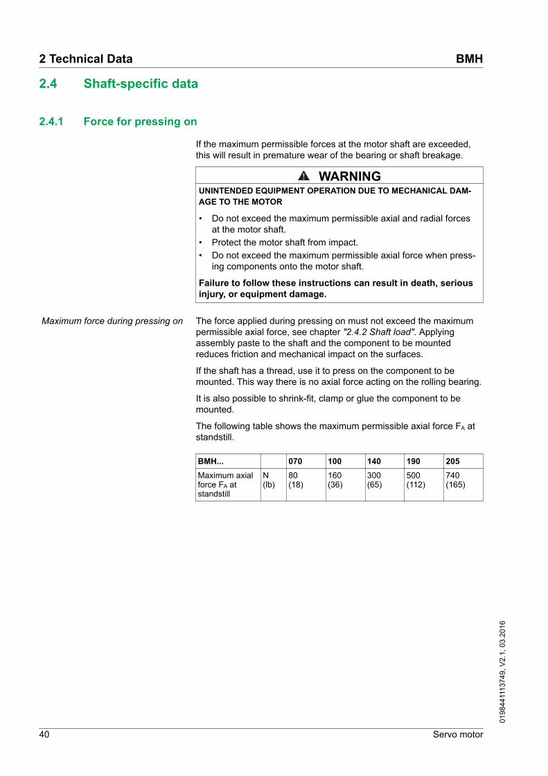
If the maximum permissible forces at the motor shaft are exceeded,this will result in premature wear of the bearing or shaft breakage.
WARNINGUNINTENDED EQUIPMENT OPERATION DUE TO MECHANICAL DAM-AGE TO THE MOTOR
• Do not exceed the maximum permissible axial and radial forcesat the motor shaft.
• Protect the motor shaft from impact.• Do not exceed the maximum permissible axial force when press-
ing components onto the motor shaft.
Failure to follow these instructions can result in death, seriousinjury, or equipment damage.
Maximum force during pressing on The force applied during pressing on must not exceed the maximumpermissible axial force, see chapter "2.4.2 Shaft load". Applyingassembly paste to the shaft and the component to be mountedreduces friction and mechanical impact on the surfaces.
If the shaft has a thread, use it to press on the component to bemounted. This way there is no axial force acting on the rolling bearing.
It is also possible to shrink-fit, clamp or glue the component to bemounted.
The following table shows the maximum permissible axial force FA atstandstill.
BMH... 070 100 140 190 205Maximum axialforce FA atstandstill
N(lb)
80(18)
160(36)
300(65)
500(112)
740(165)
2 Technical Data BMH
40 Servo motor
0198
4411
1374
9, V
2.1,
03.
2016

2.4.2 Shaft load
The following conditions apply:
• The permissible force applied during pressing on must not beexceed.
• Radial and axial limit loads must not be applied simultaneously• Nominal bearing service life in operating hours at a probability of
failure of 10% (L10h = 20000 hours)• Mean speed of rotation n = 4000 rpm• Ambient temperature = 40 °C (104 °F)• Peak torque = Duty types S3 - S8, 10% duty cycle• Nominal torque = Duty type S1, 100% duty cycle
X
FA
FR
Figure 10: Shaft load
The point of application of the forces depends on the motor size:
Motor version Values for "X"BMH0701 and BMH0702 mm (in) 11.5 (0.45)
BMH0703 mm (in) 15 (0.59)
BMH100 mm (in) 20 (0.76)
BMH140 mm (in) 25 (0.98)
BMH190 mm (in) 40 (1.57)
BMH205 mm (in) 40 (1.57)
BMH 2 Technical Data
Servo motor 41
0198
4411
1374
9, V
2.1,
03.
2016

The following table shows the maximum radial shaft load FR.
BMH... 0701 0702 0703 1001 1002 1003 1401 1402 14031000 rpm N
(lb)660(148)
710(160)
730(164)
900(202)
990(223)
1050(236)
1930(434)
2240(544)
2420(544)
2000 rpm N(lb)
520(117)
560(126)
580(130)
720(162)
790(178)
830(187)
1530(344)
1780(400)
1920(432)
3000 rpm N(lb)
460(103)
490(110)
510(115)
630(142)
690(155)
730(164)
1340(301)
1550(348)
1670(375)
4000 rpm N(lb)
410(92)
450(101)
460(103)
570(128)
620(139)
660(148)
- - -
5000 rpm N(lb)
380(85)
410(92)
430(97)
530(119)
580(130)
610(137)
- - -
6000 rpm N(lb)
360(81)
390(88)
400(90)
- - - - - -
BMH... 1901 1902 1903 1904 2051 2052 20531000 rpm N
(lb)2900(652)
3200(719)
3300(742)
3800(854)
3730(839)
4200(944)
4500(1012)
2000 rpm N(lb)
2750(618)
3100(697)
3250(731)
3700(832)
2960(665)
3330(749)
3570(803)
3000 rpm N(lb)
2650(596)
3000(674)
3150(708)
3600(809)
2580(580)
2910(654)
3120(701)
4000 rpm N(lb)
2600(585)
2950(663)
3100(697)
3500(787)
- - -
The following table shows the maximum axial shaft load FA.
BMH... 0701 0702 0703 1001 1002 1003 1401 1402 14031000 rpm N
(lb)132(30)
142(32)
146(33)
180(40)
198(45)
210(47)
386(87)
448(109)
484(109)
2000 rpm N(lb)
104(23)
112(25)
116(26)
144(32)
158(36)
166(37)
306(69)
356(86)
384(86)
3000 rpm N(lb)
92(21)
98(22)
102(23)
126(28)
138(31)
146(33)
268(60)
310(75)
334(75)
4000 rpm N(lb)
82(18)
90(20)
92(21)
114(26)
124(28)
132(30)
- - -
5000 rpm N(lb)
76(17)
82(18)
86(19)
106(24)
116(26)
122(27)
- - -
6000 rpm N(lb)
72(16)
78(18)
80(18)
- - - - - -
BMH... 1901 1902 1903 1904 2051 2052 20531000 rpm N
(lb)580(130)
640(144)
660(148)
760(171)
746 840 900
2000 rpm N(lb)
550(124)
620(139)
650(146)
740(166)
592 666 714
3000 rpm N(lb)
530(119)
600(135)
630(142)
720(162)
516 582 624
4000 rpm N(lb)
520(117)
590(133)
620(139)
700(157)
- - -
2 Technical Data BMH
42 Servo motor
0198
4411
1374
9, V
2.1,
03.
2016

If the maximum permissible forces at the motor shaft are exceeded,this will result in premature wear of the bearing or shaft breakage.
WARNINGUNINTENDED EQUIPMENT OPERATION DUE TO MECHANICAL DAM-AGE TO THE MOTOR
• Do not exceed the maximum permissible axial and radial forcesat the motor shaft.
• Protect the motor shaft from impact.• Do not exceed the maximum permissible axial force when press-
ing components onto the motor shaft.
Failure to follow these instructions can result in death, seriousinjury, or equipment damage.
BMH 2 Technical Data
Servo motor 43
0198
4411
1374
9, V
2.1,
03.
2016

2.5 Options
2.5.1 Encoder
The motors are equipped with a SinCos encoder. The drive canaccess the electronic nameplate via the Hiperface interface for com-missioning.
The signals meet the PELV requirements.
SKS36 Singleturn This motor encoder measures an absolute value within one revolutionat start-up and continues to count incrementally from this point.
Resolution in increments Depending on evaluation
Resolution per revolution 128 sin/cos periods
Measuring range absolute 1 revolution
Accuracy of the digital absolutevalue 1)
±0.0889°
Accuracy of the incremental posi-tion
±0.0222°
Signal shape Sinusoidal
Supply voltage 7 ... 12 Vdc
Maximum supply current 60 mA (without load)
Maximum angular acceleration 200,000 rad/s2
1) Depending on the evaluation through the drive, the accuracy may be increased byincluding the incremental position in the calculation of the absolute value. In thiscase, the accuracy corresponds to the incremental position.
SKM36 Multiturn This motor encoder measures an absolute value within 4096 revolu-tions at start-up and continues to count incrementally from this point.
Resolution in increments Depending on evaluation
Resolution per revolution 128 sin/cos periods
Measuring range absolute 4096 revolutions
Accuracy of the digital absolutevalue 1)
±0.0889°
Accuracy of the incremental posi-tion
±0.0222°
Signal shape Sinusoidal
Supply voltage 7 ... 12 Vdc
Maximum supply current 60 mA (without load)
Maximum angular acceleration 200,000 rad/s2
1) Depending on the evaluation through the drive, the accuracy may be increased byincluding the incremental position in the calculation of the absolute value. In thiscase, the accuracy corresponds to the incremental position.
2 Technical Data BMH
44 Servo motor
0198
4411
1374
9, V
2.1,
03.
2016

SEK37 Singleturn This motor encoder measures an absolute value within one revolutionat start-up and continues to count incrementally from this point.
Resolution in increments Depending on evaluation
Resolution per revolution 16 sin/cos periods
Measuring range absolute 1 revolution
Accuracy of position ± 0.08°
Signal shape Sinusoidal
Supply voltage 7 ... 12 Vdc
Maximum supply current 50 mA (without load)
SEL37 Multiturn This motor encoder measures an absolute value within 4096 revolu-tions at start-up and continues to count incrementally from this point.
Resolution in increments Depending on evaluation
Resolution per revolution 16 sin/cos periods
Measuring range absolute 4096 revolutions
Accuracy of position ± 0.08°
Signal shape Sinusoidal
Supply voltage 7 ... 12 Vdc
Maximum supply current 50 mA (without load)
BMH 2 Technical Data
Servo motor 45
0198
4411
1374
9, V
2.1,
03.
2016

2.5.2 Holding brake
BMH... 070 1001,1002
1003 1401,1402
1403 1901 1902,1903
1904,205
Holding torque 1) Nm(lb⋅in)
3.0(26.55)
5.5(48.68)
9(79.66)
18(159.3)
23(203.6)
32(283.2)
60(531.0)
80(708.1)
Holding brake release time ms 80 70 90 100 100 200 220 200
Holding brake application time ms 17 30 40 52 60 60 50 50
Nominal voltage Vdc 24 +5/-15% 24+6/-10%
Nominal power(electrical pull-in power)
W 7 12 18 18 19 23 25 40
Maximum speed of rotation duringbraking of moving loads
rpm 3000
Maximum number of decelera-tions during braking of movingloads and 3000 rpm
500
Maximum number of decelera-tions during braking of movingloads per hour (at even distribu-tion)
20
Maximum kinetic energy that canbe transformed into heat perdeceleration during braking ofmoving loads
J 130 150 150 550 550 850 850 21000
1) The holding brake is broken-in at the factory. If the holding brake is not used for an extended period of time, parts of the holdingbrake may corrode. Corrosion reduces the holding torque. See "Inspecting/breaking in the holding brake" in chapter"7 Service, maintenance and disposal".
For a description of the controller, see chapter"3.5.3 Holding brake connection".
2.5.3 Fan (BMH1904∙∙∙∙∙B only)
BMH... 1904∙∙∙∙∙BNominal voltage Vdc 24
Nominal voltage range Vdc 16 ... 30
Input current A 1.4
Input power W 34
Nominal speed of rotation rpm 4400
Sound pressure level dB(A) 56
2.6 Conditions for UL 1004-1, UL 1004-6 and CSA 22.2 No. 100
PELV power supply Use only power supply units that are approved for overvoltage cate-gory III.
Wiring Use at least 60/75 °C (140/167 °F) copper conductors.
2 Technical Data BMH
46 Servo motor
0198
4411
1374
9, V
2.1,
03.
2016

2.7 Certifications
Product certifications:
Certified by Assigned numberUL File E208613
BMH 2 Technical Data
Servo motor 47
0198
4411
1374
9, V
2.1,
03.
2016

2.8 Declaration of conformity
The declaration of conformity can be downloaded from the Internet at:
http://www.schneider-electric.com/download
2 Technical Data BMH
48 Servo motor
0198
4411
1374
9, V
2.1,
03.
2016

3 Installation
DANGERELECTRIC SHOCK CAUSED BY INSUFFICIENT GROUNDING
• Verify compliance with all local and national electrical coderequirements as well as all other applicable regulations withrespect to grounding of the entire drive system.
• Ground the drive system before applying voltage.• Do not use conduits as protective ground conductors; use a pro-
tective ground conductor inside the conduit.• The cross section of the protective ground conductor must com-
ply with the applicable standards.• Do not consider cable shields to be protective ground conductors.
Failure to follow these instructions will result in death or seri-ous injury.
DANGERELECTRIC SHOCK OR UNINTENDED EQUIPMENT OPERATION
• Keep foreign objects from getting into the product.• Verify the correct seating of seals and cable entries in order to
avoid contamination such as deposits and humidity.
Failure to follow these instructions will result in death or seri-ous injury.
Motors are very heavy relative to their size. The great mass of themotor can cause injuries and damage.
WARNINGHEAVY AND/OR FALLING PARTS
• Use a suitable crane or other suitable lifting gear for mounting themotor if this is required by the weight of the motor.
• Use the necessary personal protective equipment (for example,protective shoes, protective glasses and protective gloves).
• Mount the motor so that it cannot come loose (use of securingscrews with appropriate tightening torque), especially in cases offast acceleration or continuous vibration.
Failure to follow these instructions can result in death, seriousinjury, or equipment damage.
BMH 3 Installation
Servo motor 49
0198
4411
1374
9, V
2.1,
03.
2016
Motors can generate strong local electrical and magnetic fields. Thiscan cause interference in sensitive devices.
WARNINGELECTROMAGNETIC FIELDS
• Keep persons with electronic medical implants, such as pace-makers, away from the motor.
• Do not place electromagnetically sensitive devices in the vicinityof the motor.
Failure to follow these instructions can result in death, seriousinjury, or equipment damage.
The metal surfaces of the product may exceed 70 °C (158 °F) duringoperation.
WARNINGHOT SURFACES
• Avoid unprotected contact with hot surfaces.• Do not allow flammable or heat-sensitive parts in the immediate
vicinity of hot surfaces.• Verify that the heat dissipation is sufficient by performing a test
run under maximum load conditions.
Failure to follow these instructions can result in death, seriousinjury, or equipment damage.
CAUTIONIMPROPER APPLICATION OF FORCES
• Do not use the motor as a step to climb into or onto the machine.• Do not use the motor as a load-bearing part.• Use hazard labels and guards on your machine to help prevent
the improper application of forces on the motor.
Failure to follow these instructions can result in injury or equip-ment damage.
3 Installation BMH
50 Servo motor
0198
4411
1374
9, V
2.1,
03.
2016

3.1 Overview of procedure
Chapter Page"3.2 Electromagnetic compatibility (EMC)" 51
"3.3 Before mounting" 54
"3.4 Mounting the motor " 60
"3.5 Electrical installation" 65
3.2 Electromagnetic compatibility (EMC)
The measures for electromagnetic compatibility (EMC) are intended tominimize electromagnetic interference of the device and interferencecaused by the device that affects the environment. Such measuresinclude measures to reduce interference and emission as well as toincrease immunity.
Electromagnetic compatibility hinges to a great extent on the individ-ual components used in the system. The EMC measures described inthis manual may help to comply with the requirements of IEC 61800-3.You must comply with all EMC regulations of the country in which theproduct is operated. Also, respect any special EMC regulations thatmay apply at the installation site (for example, residential environ-ments or airports).
Signal interference can cause unexpected responses of the drive sys-tem and of other equipment in the vicinity of the drive system.
WARNINGSIGNAL AND EQUIPMENT INTERFERENCE
• Install the wiring in accordance with the EMC requirementsdescribed in the present document.
• Verify compliance with the EMC requirements described in thepresent document.
• Verify compliance with all EMC regulations and requirementsapplicable in the country in which the product is to be operatedand with all EMC regulations and requirements applicable at theinstallation site.
Failure to follow these instructions can result in death, seriousinjury, or equipment damage.
BMH 3 Installation
Servo motor 51
0198
4411
1374
9, V
2.1,
03.
2016

Motor and encoder cables In terms of EMC, motor cables are especially critical since they areparticularly prone to causing interference.
When planning the wiring, take into account the fact that the motorcable must be routed separately. The motor cable must be separatefrom mains cables or signal cables (for example, limit switches). Useonly pre-assembled cables or cables that comply with the specifica-tions and implement the EMC measures described below.
EMC measures EffectKeep cables as short as possible. Do notinstall unnecessary cable loops, use shortcables from the central grounding point inthe control cabinet to the external groundconnection.
Reduces capacitive and induc-tive interference.
Ensure that there is a ground connectionbetween the motor flange and the mountingsurface on the machine (no paint, oil andgrease or any insulating material betweenthe motor flange and the mounting surfaceon the machine).
Reduces emissions, increasesimmunity.
Connect large surface areas of cableshields, use cable clamps and groundstraps.
Reduces emissions.
Do not install switching elements in motorcables or encoder cables.
Reduces interference.
Route the motor cable separately from mainscables and signal cables (for example, forlimit switches), for example by using shield-ing plates or by keeping the cables apartfrom each other at a distance of at least 20cm (5.08 in).
Reduces mutual interference
Route the motor cable and encoder cablewithout cutting them. 1)
Reduces emission.
1) If a cable is cut for the installation, take appropriate measures for uninterruptedshielding (such as a metal housing) at the point of the cut. Connect a large area ofthe cable shield to the metal housing at both ends of the cut.
Pre-assembled motor cables with various lengths are available for thedrive solutions. Contact your local sales office.
Pre-assembled connection cables(accessories)
Using pre-assembled cables helps to reduce the possibility of wiringerrors. See chapter "6 Accessories and spare parts".
Place the female connector of the motor cable onto the motor connec-tor and tighten the union nut. Proceed in the same manner with theconnection cable of the encoder system. Connect the motor cable andthe encoder cable to the drive according to the wiring diagram of thedrive.
Equipotential bonding conductors Potential differences can result in excessive currents on the cableshields. Use equipotential bonding conductors to reduce currents onthe cable shields. The equipotential bonding conductor must be ratedfor the maximum current.
3 Installation BMH
52 Servo motor
0198
4411
1374
9, V
2.1,
03.
2016

WARNINGUNINTENDED EQUIPMENT OPERATION
• Ground cable shields for all fast I/O, analog I/O, and communica-tion signals at a single point. 1)
• Route communications and I/O cables separately from powercables.
Failure to follow these instructions can result in death, seriousinjury, or equipment damage.
1) Multipoint grounding is permissible if connections are made to an equipotentialground plane dimensioned to help avoid cable shield damage in the event of powersystem short-circuit currents.
BMH 3 Installation
Servo motor 53
0198
4411
1374
9, V
2.1,
03.
2016

3.3 Before mounting
Inspecting the product ▶ Verify the product version by means of the type code on the name-plate. See chapter "1.3 Nameplate" and chapter "1.4 Type code".
▶ Prior to mounting, inspect the product for visible damage.
Damaged products may cause electric shock or unintended equip-ment operation.
DANGERELECTRIC SHOCK OR UNINTENDED EQUIPMENT OPERATION
• Do not use damaged products.• Keep foreign objects (such as chips, screws or wire clippings)
from getting into the product.
Failure to follow these instructions will result in death or seri-ous injury.
Contact your local Schneider Electric sales office if you detect anydamage whatsoever to the products.
Inspecting the holding brake(option)
See chapter "7.2 Maintenance", section"Inspecting/breaking in the holding brake".
Cleaning the shaft The shaft extensions are factory-treated with an anti-corrosive. If out-put components are glued to the shaft, the anti-corrosive must beremoved and the shaft cleaned. If required, use a grease removalagent as specified by the glue manufacturer. If the glue manufacturerdoes not provide information on grease removal, acetone may beused.
▶ Remove the anti-corrosive. Avoid direct contact of the skin and thesealing material with the anti-corrosive or the cleaning agent.
Mounting surface for flange The mounting surface must be stable, clean, deburred and low-vibra-tion. Ensure that the mounting surface is itself grounded, and that apotential exists between the motor flange and the mounting surface.
DANGERELECTRIC SHOCK CAUSED BY INSUFFICIENT GROUNDING
• Verify compliance with all local and national electrical coderequirements as well as all other applicable regulations withrespect to grounding of the entire drive system.
• Ground the drive system before applying voltage.• Do not use conduits as protective ground conductors; use a pro-
tective ground conductor inside the conduit.• The cross section of the protective ground conductor must com-
ply with the applicable standards.• Do not consider cable shields to be protective ground conductors.
Failure to follow these instructions will result in death or seri-ous injury.
▶ Verify that the mounting surface meets all requirements in terms ofdimensions and tolerances. See chapter "2.3 Dimensions" fordimensions.
3 Installation BMH
54 Servo motor
0198
4411
1374
9, V
2.1,
03.
2016

Conductor cross sections accord-ing to method of installation
The following sections describe the conductor cross sections for twomethods of installation:
• Method of installation B2:
Cables in conduits or cable trunking systems• Method of installation E:
Cables on open cable trays
Cross section inmm2 (AWG) 1)
Current-carryingcapacity with method ofinstallation B2 in A 2)
Current carryingcapacity with method ofinstallation E in A 2)
0.75 (18) 8.5 10.4
1 (16) 10.1 12.4
1.5 (14) 13.1 16.1
2.5 (12) 17.4 22
4 (10) 23 30
6 (8) 30 37
10 (6) 40 52
16 (4) 54 70
25 (2) 70 881) See chapter "6 Accessories and spare parts" for available cables.2) Values as per IEC 60204-1 for continuous operation, copper conductors and ambi-
ent air temperature 40°C (104 °F); see IEC 60204-1 for additional information.
Note the derating factors for grouping of cables and correction factorsfor other ambient conditions (IEC 60204-1).
The conductors must have a sufficiently large cross section so that theupstream fuse can trip.
In the case of longer cables, it may be necessary to use a greaterconductor cross section to reduce the energy losses.
BMH 3 Installation
Servo motor 55
0198
4411
1374
9, V
2.1,
03.
2016

Cable specifications Using pre-assembled cables helps to reduce the possibility of wiringerrors. See chapter "6 Accessories and spare parts".
The genuine accessories have the following properties:
Cables with connectors VW3M5101 VW3M5102 VW3M5103 VW3M5105 VW3M5104Cable jacket, insulation PUR orange (RAL 2003), polypropylene (PP)
CapacitanceWire/wireWire/shield
pF/mpF/m
80135
80150
90150
85150
100160
Number of contacts (shielded) 4 x 1.5 mm2 +2 x 1 mm2
4 x 2.5 mm2 +2 x 1 mm2
4 x 4 mm2 +2 x 1 mm2
4 x 6 mm2 +2 x 1 mm2
4 x 10 mm2 +2 x 1 mm2
Connection version Motor end 8-pin circular con-nector M23, other cable endopen
Motor end 8-pin circular connector M40, othercable end open
Cable diameter mm(in)
12 ± 0.2(0.47 ± 0.01)
14.3 ± 0.3(0.55 ± 0.01)
16.3 ± 0.3(0.64 ± 0.01)
18.8 ± 0.4(0.74 ± 0.02)
23.5 ± 0.6(0.93 ± 0.02)
Minimum bend radius with per-manently installed connection
5 times the cable diameter
Minimum bend radius with flexi-ble installation
7.5 times the cable diameter 10 times the cable diameter
Nominal voltageMotor phasesHolding brake
V600300
Maximum orderable length m (ft) 75 (246)
Permissible temperature rangeduring operation with perma-nently installed connection
°C (°F) -40 ... 80 (-40 ... 176)
Permissible temperature rangeduring operation with flexibleinstallation
°C (°F) -20 ... 80 (-4 ... 176)
Certifications / declaration ofconformity
CE, DESINA
3 Installation BMH
56 Servo motor
0198
4411
1374
9, V
2.1,
03.
2016
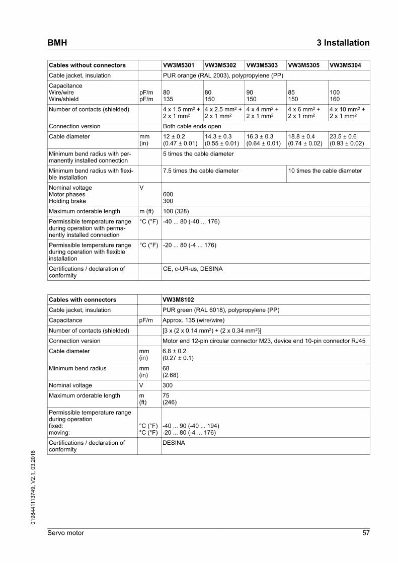
Cables without connectors VW3M5301 VW3M5302 VW3M5303 VW3M5305 VW3M5304Cable jacket, insulation PUR orange (RAL 2003), polypropylene (PP)
CapacitanceWire/wireWire/shield
pF/mpF/m
80135
80150
90150
85150
100160
Number of contacts (shielded) 4 x 1.5 mm2 +2 x 1 mm2
4 x 2.5 mm2 +2 x 1 mm2
4 x 4 mm2 +2 x 1 mm2
4 x 6 mm2 +2 x 1 mm2
4 x 10 mm2 +2 x 1 mm2
Connection version Both cable ends open
Cable diameter mm(in)
12 ± 0.2(0.47 ± 0.01)
14.3 ± 0.3(0.55 ± 0.01)
16.3 ± 0.3(0.64 ± 0.01)
18.8 ± 0.4(0.74 ± 0.02)
23.5 ± 0.6(0.93 ± 0.02)
Minimum bend radius with per-manently installed connection
5 times the cable diameter
Minimum bend radius with flexi-ble installation
7.5 times the cable diameter 10 times the cable diameter
Nominal voltageMotor phasesHolding brake
V600300
Maximum orderable length m (ft) 100 (328)
Permissible temperature rangeduring operation with perma-nently installed connection
°C (°F) -40 ... 80 (-40 ... 176)
Permissible temperature rangeduring operation with flexibleinstallation
°C (°F) -20 ... 80 (-4 ... 176)
Certifications / declaration ofconformity
CE, c-UR-us, DESINA
Cables with connectors VW3M8102Cable jacket, insulation PUR green (RAL 6018), polypropylene (PP)
Capacitance pF/m Approx. 135 (wire/wire)
Number of contacts (shielded) [3 x (2 x 0.14 mm2) + (2 x 0.34 mm2)]
Connection version Motor end 12-pin circular connector M23, device end 10-pin connector RJ45
Cable diameter mm(in)
6.8 ± 0.2(0.27 ± 0.1)
Minimum bend radius mm(in)
68(2.68)
Nominal voltage V 300
Maximum orderable length m(ft)
75(246)
Permissible temperature rangeduring operationfixed:moving:
°C (°F)°C (°F)
-40 ... 90 (-40 ... 194)-20 ... 80 (-4 ... 176)
Certifications / declaration ofconformity
DESINA
BMH 3 Installation
Servo motor 57
0198
4411
1374
9, V
2.1,
03.
2016

Cables without connectors VW3M8222Cable jacket, insulation PUR green (RAL 6018), polypropylene (PP)
Capacitance pF/m Approx. 135 (wire/wire)
Number of contacts (shielded) [3 x (2 x 0.14 mm2) + (2 x 0.34 mm2)]
Connection version Both cable ends open
Cable diameter mm(in)
6.8 ± 0.2(0.27 ± 0.1)
Minimum bend radius mm(in)
68(2.68)
Nominal voltage V 300
Maximum orderable length m(ft)
100(328)
Permissible temperature rangeduring operationfixed:moving:
°C (°F)°C (°F)
-40 ... 90 (-40 ... 194)-20 ... 80 (-4 ... 176)
Certifications / declaration ofconformity
c-UR-us, DESINA
3 Installation BMH
58 Servo motor
0198
4411
1374
9, V
2.1,
03.
2016

Space for connectors
LMLM LS
LR
LC
LS
LR
LC
∅D
∅D
Rmin
∅d
Rmin
∅d
Figure 11: Connector installation space
Dimen-sions
Motor connec-torsstraightBMH070 ... 140
Motor connec-torsstraightBMH205
Encoder connec-torstraight
D mm (in) 28 (1.10) 46 (1.81) 26 (1.02)
LS mm (in) 76 (2.99) 100 (3.94) 51 (2.01)
LR mm (in) 117 (4.61) 155 (6.10) 76 (2.99)
LC mm (in) 100 (3.94) 145 (5.71) 60 (2.36)
LM mm (in) 40 (1.57) 54 (2.13) 23 (0.91)
Dimen-sions
Motor connec-torsangularBMH070 ... 140
Motor connec-torsangularBMH190 ... 205
Encoder connec-torangular
D mm (in) 28 (1.10) 46 (1.81) 26 (1.02)
LS mm (in) 76 (2.99) 100 (3.94) 51 (2.01)
LR mm (in) 132 (5.20) 191 (7.52) 105 (4.13)
LC mm (in) 114 (4.49) 170 (6.69) 89 (3.50)
LM mm (in) 55 (2.17) 91 (3.58) 52 (2.05)
Dimen-sions
Motor cablesBMH070 ... 140
Motor cablesBMH190 ... 205
Encoder cables
d mm (in) 18 (0.71) 25 (0.98) 18 (0.71)
Rmin mm (in) 90 (3.54) 125 (4.92) 68 (2.68)
BMH 3 Installation
Servo motor 59
0198
4411
1374
9, V
2.1,
03.
2016

3.4 Mounting the motor
Electrostatic discharge to the shaft may cause incorrect operation ofthe encoder system and result in unanticipated motor movements anddamage to the bearing.
WARNINGUNINTENDED MOVEMENT CAUSED BY ELECTROSTATIC DISCHARGE
Use conductive components such as antistatic belts or other suitablemeasures to avoid static charge by motion.
Failure to follow these instructions can result in death, seriousinjury, or equipment damage.
If the permissible ambient conditions are not respected, external sub-stances from the environment may penetrate the product and causeunintended movement or equipment damage.
WARNINGUNINTENDED MOVEMENT
• Verify that the ambient conditions are respected.• Do not allow seals to run dry.• Keep liquids from getting to the shaft bushing (for example, in
mounting position IM V3).• Do not expose the shaft sealing rings and cable entries of the
motor to the direct spray of a pressure washer.
Failure to follow these instructions can result in death, seriousinjury, or equipment damage.
The metal surfaces of the product may exceed 70 °C (158 °F) duringoperation.
WARNINGHOT SURFACES
• Avoid unprotected contact with hot surfaces.• Do not allow flammable or heat-sensitive parts in the immediate
vicinity of hot surfaces.• Verify that the heat dissipation is sufficient by performing a test
run under maximum load conditions.
Failure to follow these instructions can result in death, seriousinjury, or equipment damage.
3 Installation BMH
60 Servo motor
0198
4411
1374
9, V
2.1,
03.
2016

NOTICEFORCES APPLIED TO THE REAR SIDE OF THE MOTOR
• Do not place the motor on the rear side.• Protect the rear side of the motor from impact.• Do not lift motors via the rear side.• Lift motors equipped with eyebolts only via the eyebolts.
Failure to follow these instructions can result in equipmentdamage.
Mounting position The following mounting positions are defined and permissible as perIEC 60034-7:
IM B5 IM V1 IM V3
Special characteristics BMH190
F1
Figure 12: BMH190 rear side of motor
(1) Protect the rear side of the motor from application of forces.
Consider the mass of the product when mounting the motor. It may benecessary to use suitable lifting gear.
BMH 3 Installation
Servo motor 61
0198
4411
1374
9, V
2.1,
03.
2016

BMH1901, BMH1902, BMH1903 BMH1904
Mounting When the motor is mounted to the mounting surface, it must be accu-rately aligned axially and radially and make even contact with themounting surface. All mounting screws must be tightened with thespecified tightening torque. No uneven mechanical load must beapplied when the mounting screws are tightened. See chapter"2 Technical Data" for data, dimensions and degrees of protection(IP).
Mounting output components Output components such as pulleys and couplings must be mountedwith suitable equipment and tools. Motor and output component mustbe accurately aligned both axially and radially. If the motor and theoutput component are not accurately aligned, this will cause runoutand premature wear.
The maximum axial and radial forces acting on the shaft must notexceed the maximum shaft load values specified, see chapter"2.4.2 Shaft load".
If the maximum permissible forces at the motor shaft are exceeded,this results in premature wear of the bearing, shaft breakage or dam-age to the encoder.
WARNINGUNINTENDED EQUIPMENT OPERATION DUE TO MECHANICAL DAM-AGE TO THE MOTOR
• Do not exceed the maximum permissible axial and radial forcesat the motor shaft.
• Protect the motor shaft from impact.• Do not exceed the maximum permissible axial force when press-
ing components onto the motor shaft.
Failure to follow these instructions can result in death, seriousinjury, or equipment damage.
3 Installation BMH
62 Servo motor
0198
4411
1374
9, V
2.1,
03.
2016

3.4.1 Installation and connection of IP67 kit (accessory)
The IP67 kit is used to connect compressed air to the motor. Degreeof protection IP65 is a prerequisite for the use of the IP67 kit. Thecompressed air generates a permanent overpressure inside themotor. This overpressure inside the motor is used to obtain degree ofprotection IP67.
Note the special requirements in terms of the compressed air in chap-ter "2 Technical Data".
Installation: BMH070, BMH100,BMH140 and BMH205
When the IP67 kit is installed, the existing cover is replaced by thecover of the IP67 kit. The O-ring is also replaced (shipped with theIP67 kit).
Figure 13: Installation IP67 Kit
▶ Loosen the 4 housing screws of the cover.▶ Remove the cover and the O-ring▶ Verify proper seat of the O-ring in the cover of the IP67 kit.
To facilitate mounting of the new O-ring, you may slightly greasethe O-ring to hold it in place.
▶ Fasten the cover of the IP67 kit with the 4 housing screws.
Tightening torque of housing screws M3 Nm (lb∙in) 1 (8.85)
Tightening torque of housing screws M4 Nm (lb∙in) 1.5 (13.28)
Tightening torque of housing screws M5 Nm (lb∙in) 5 (44.3)
▶ Verify the tightening torque of the compressed air connection:
Tightening torque compressed air connection Nm (lb∙in) 0.6 (5.31)
BMH 3 Installation
Servo motor 63
0198
4411
1374
9, V
2.1,
03.
2016

Installation: BMH190 For installation, the existing screw plug is replaced by an L-shapedpush-in fitting. See page 87 for sources of supply of the L-shapedpush-in fitting.
1 2 3
Figure 14: Installation L-shaped push-in fitting BMH190
▶ (1) and (2): Remove the screw plug.▶ (3) Screw the L-shaped push-in fitting into the thread.▶ Verify proper seat of the L-shaped push-in fitting.▶ Verify the tightening torque of the L-shaped push-in fitting:
Tightening torque L-shaped push-in fit-ting
Nm (lb∙in) 0.6 (5.31)
Compressed air connection The compressed air connection of the L-shaped push-in fitting isdesigned for compressed air hoses made of standard plastic with anominal diameter of 4 mm.
Compressed air monitoring Use a compressed air monitor.
3 Installation BMH
64 Servo motor
0198
4411
1374
9, V
2.1,
03.
2016

3.5 Electrical installation
3.5.1 Connectors and connector assignments
Connection overviewCN1M23
CN2M23
CN1M23
CN2M23
CN1M23
CN2M23
Figure 15: Connection overview BMH070, BMH100 and BMH140
CN2M23
CN1M40
CN3
CN2M23
CN1M40
Figure 16: Connection overview BMH1904∙∙∙∙∙A and BMH1904∙∙∙∙∙B
CN1M40
CN2M23
Figure 17: Connection overview BMH205
BMH 3 Installation
Servo motor 65
0198
4411
1374
9, V
2.1,
03.
2016

CN1 motor connection M23 Motor connector for connection of the motor phases and the holdingbrake.
3 14 A
BC
D
3 14
ABCDFigure 18: Pin assignment motor connection M23
See chapter "6.2 Connectors" for suitable mating connectors.
The signals of the holding brake meet the PELV requirements.
Pin Assignment Meaning1 U Motor phase U
PE Protective ground conductor
3 W Motor phase W
4 V Motor phase V
A BR+ Supply voltage holding brake 24 Vdc
B BR- Reference potential holding brake 0 Vdc
C Reserved Reserved
D Reserved ReservedSHLD Shield (to connector housing)
3 Installation BMH
66 Servo motor
0198
4411
1374
9, V
2.1,
03.
2016

CN1 motor connection M40 Motor connector for connection of the motor phases and the holdingbrake.
12
+-W V U
12
+-
W
V
U
Figure 19: Pin assignment motor connection M40
See chapter "6.2 Connectors" for suitable mating connectors.
The signals of the holding brake meet the PELV requirements.
Pin Assignment MeaningU U Motor phase U
PE Protective ground conductor
W W Motor phase W
V V Motor phase V
+ BR+ Supply voltage holding brake 24 Vdc
- BR- Reference potential holding brake 0 Vdc
1 Reserved Reserved
2 Reserved ReservedSHLD Shield (to connector housing)
BMH 3 Installation
Servo motor 67
0198
4411
1374
9, V
2.1,
03.
2016
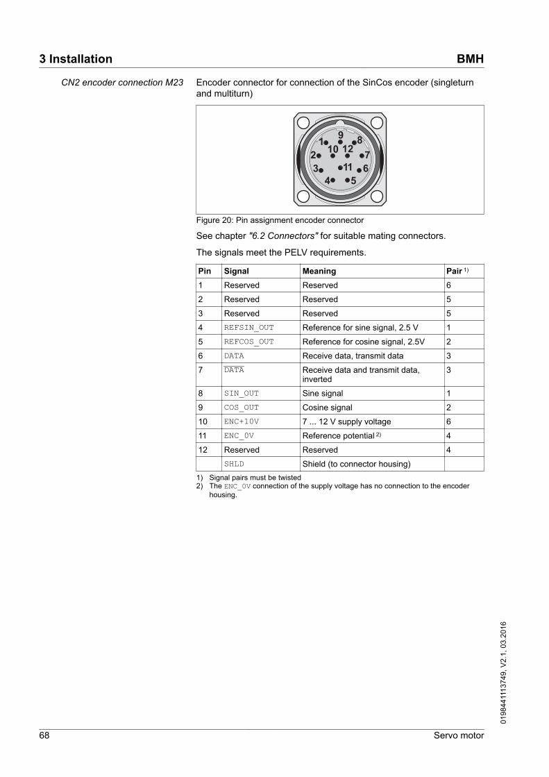
CN2 encoder connection M23 Encoder connector for connection of the SinCos encoder (singleturnand multiturn)
1 9
43
1026
5
78
12
11
Figure 20: Pin assignment encoder connector
See chapter "6.2 Connectors" for suitable mating connectors.
The signals meet the PELV requirements.
Pin Signal Meaning Pair 1)
1 Reserved Reserved 6
2 Reserved Reserved 5
3 Reserved Reserved 5
4 REFSIN_OUT Reference for sine signal, 2.5 V 1
5 REFCOS_OUT Reference for cosine signal, 2.5V 2
6 DATA Receive data, transmit data 3
7 DATA Receive data and transmit data,inverted
3
8 SIN_OUT Sine signal 1
9 COS_OUT Cosine signal 2
10 ENC+10V 7 ... 12 V supply voltage 6
11 ENC_0V Reference potential 2) 4
12 Reserved Reserved 4SHLD Shield (to connector housing)
1) Signal pairs must be twisted2) The ENC_0V connection of the supply voltage has no connection to the encoder
housing.
3 Installation BMH
68 Servo motor
0198
4411
1374
9, V
2.1,
03.
2016
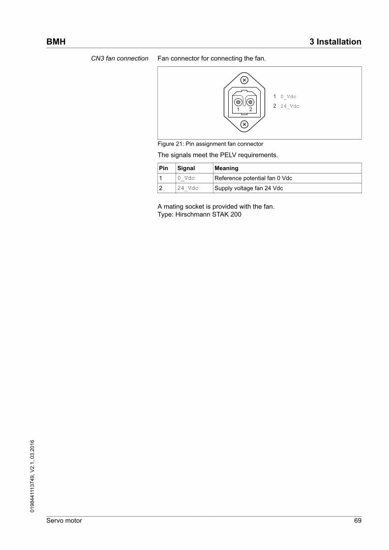
CN3 fan connection Fan connector for connecting the fan.
1 0_Vdc2 24_Vdc
21
Figure 21: Pin assignment fan connector
The signals meet the PELV requirements.
Pin Signal Meaning1 0_Vdc Reference potential fan 0 Vdc
2 24_Vdc Supply voltage fan 24 Vdc
A mating socket is provided with the fan.Type: Hirschmann STAK 200
BMH 3 Installation
Servo motor 69
0198
4411
1374
9, V
2.1,
03.
2016

3.5.2 Power and encoder connection
High voltages may be present at the motor connection. The motoritself generates voltage when the motor shaft is rotated. AC voltagecan couple voltage to unused conductors in the motor cable.
DANGERELECTRIC SHOCK
• Verify that no voltage is present prior to performing any type ofwork on the drive system.
• Block the motor shaft to prevent rotation prior to performing anytype of work on the drive system.
• Insulate both ends of unused conductors of the motor cable.• Only touch the motor shaft or the mounted output components if
all power has been disconnected.• Verify compliance with all local and national electrical code
requirements as well as all other applicable regulations withrespect to grounding of all equipment.
Failure to follow these instructions will result in death or seri-ous injury.
The motor is designed for operation via a drive. Connecting the motordirectly to AC voltage will damage the motor and can cause fires.
DANGERFIRE HAZARD DUE TO INCORRECT CONNECTION
Only connect the motor to a matching, approved drive in the waydescribed in the present documentation.
Failure to follow these instructions will result in death or seri-ous injury.
Drive systems may perform unintended movements if unapprovedcombinations of drive and motor are used. Even if motors are similar,different adjustment of the encoder system may be a source of haz-ards. Even if the connectors for motor connection and encoder con-nection match mechanically, this does not imply that the motor isapproved for use.
WARNINGUNINTENDED MOVEMENT
Only use approved combinations of drive and motor.
Failure to follow these instructions can result in death, seriousinjury, or equipment damage.
See chapter "2.1 General characteristics" for approved drives.
3 Installation BMH
70 Servo motor
0198
4411
1374
9, V
2.1,
03.
2016

Protective ground conductor con-nection
▶ Ground the motor via a grounding screw if grounding via the flangeand the protective ground conductor of the motor cable is not suffi-cient. Use parts with suitable corrosion protection. Note therequired tightening torque and the property class of the groundingscrew, see page 24.
BMH 3 Installation
Servo motor 71
0198
4411
1374
9, V
2.1,
03.
2016

Assembling cables Insulate unused wires individually.
▶ Note the EMC requirements for motor cables and encoder cables,page 52.
▶ Use equipotential bonding conductors for equipotential bonding.
Follow the procedure and note the dimensions in"Dimensions for motor connector M23".
Depending on the motor size, different connector sizes are used forthe motor connection CN1. BMH070, BMH100 and BMH140 have anM23 connection. BMH190 and BMH205 have an M40 connection. Theencoder connection CN2 is identical irrespective of the motor size.
1
3
A
4
2
5
BK U1BK V2BK W3GN/YE
WHGY
C
B
D
II VIVIIII
Figure 22: Assembling motor cables with M23 motor connector
3 Installation BMH
72 Servo motor
0198
4411
1374
9, V
2.1,
03.
2016

▶ (1) Strip the cable jacket; length as specified (see table below).▶ Open the shielding braid and slide it back over the outer cable
jacket.▶ Shorten the inner cable jacket.▶ (2) Shorten the wires to the specified length (see table below) and
crimp them to the connector.
If possible, also connect unused wires. This improves EMC. Wiresthat are not connected must be insulated at both ends.
▶ (3) Push part (V) and part (IV) onto the cable. Snap the contactsinto part (II). Open the side of part (III) and enclose the wires usingthis part.
▶ (4) Slide part (III) behind the shielding braid and insert part (II) intopart (I). Arrange the shielding braid as shown. Push part (I) andpart (III) together and shorten the shielding braid.
▶ Screw part (IV) onto part (I) all the way to the stop.
1
3
4
2
5
BK U1BK V2BK W3GN/YE
WHGY
C
A
6
B
D
II
I
IVIII
Figure 23: Assembling motor cables with M40 motor connector
BMH 3 Installation
Servo motor 73
0198
4411
1374
9, V
2.1,
03.
2016

▶ (1) Strip the cable jacket; length as specified (see table below).▶ Open the shielding braid and slide it back over the outer cable
jacket.▶ Shorten the inner cable jacket.▶ (2) Shorten the wires to the specified length (see table below) and
crimp them to the connector.
If possible, also connect unused wires. This improves EMC. Wiresthat are not connected must be insulated at both ends.
▶ (3) Push part (IV) and part (III) onto the cable. Snap the contactslaterally into part (II).
▶ (4) Slide part (III) behind the shielding braid and insert part (II) intopart (I).
▶ (5) Arrange the shielding braid as shown. Push part (I) and part (III)together and shorten the shielding braid.
▶ Screw part (IV) onto part (I) all the way to the stop.
A
B
C
1
3
4
2
5
II VIIII VIIVIIV
Figure 24: Assembling encoder cables with M23 encoder connector
3 Installation BMH
74 Servo motor
0198
4411
1374
9, V
2.1,
03.
2016

▶ (1) Strip the cable jacket; length as specified (see table below).▶ Open the shielding braid and slide it back over the outer cable
jacket.▶ Shorten the inner cable jacket.▶ (2) Shorten the wires to the specified length (see table below) and
crimp them to the connector.
If possible, also connect unused wires. This improves EMC. Wiresthat are not connected must be insulated at both ends.
▶ (3) Push part (VII) and part (VI) onto the cable. The cable entrycontains rubber seals of various sizes for different cable diameters.Use rubber seals matching the diameter of the cable. Enclose theshield with part (IV). Snap the contacts into part (II). Open part (III)at the side and enclose part (II) as well as the rear part of the con-tacts with it. Slide part (II) into part (I).
▶ (4) Slide part (IV) behind the shielding braid. Slide part (VI) overpart (I).
▶ Screw part (IV) onto part (I) all the way to the stop.
Dimensions for motor connectorM23 Motor phases
1.5 mm2 / 2.5 mm2Holding brake1 mm2
Stripping length A 40 mm (1.57 in) 40 mm (1.57 in)
Stripping length B 36 mm (1.42 in) -
Stripping length C - 40 mm (1.57 in)
Stripping length D 8 mm (0.31 in) 4.5 mm (0.18 in)
Crimp contact SF-7QS2000 SF-6AS2000
Crimping tool SF-Z0025 SF-Z0025
Dimensions for motor connectorM40 Motor phases
4 mm2Motor phases6 mm2 / 10 mm2
Holding brake1 mm2
Stripping length A 40 mm (1.57 in) 40 mm (1.57 in) 40 mm (1.57 in)
Stripping length B 36 mm (1.42 in) 36 mm (1.42 in) -
Stripping length C - - 40 mm (1.57 in)
Stripping length D 10 mm (0.39 in) 10 mm (0.39 in) 4.5 mm (0.18 in)
Crimp contact SM-36KS002 SM-36KS004 SF-7NS2000
Crimping tool SF-Z0025 SF-Z0026 SF-Z0025
Dimensions for encoder connectorM23 Encoder
0.14 mm2 / 0.34 mm2
Stripping length A 28 mm (1.1 in)
Stripping length B 28 mm (1.1 in)
Stripping length C 4.5 mm (0.18 in)
Crimp contact RC-12S2000
Crimping tool RC-Z2514
BMH 3 Installation
Servo motor 75
0198
4411
1374
9, V
2.1,
03.
2016

Connecting the cables Incorrect installation of the cable may damage the insulation. Brokenconductors in the cable or improperly connected connectors may pro-mote arcing within the cable.
DANGERELECTRIC SHOCK, ARC FLASH AND FIRE CAUSED BY INCORRECTINSTALLATION OF THE CABLE
• Disconnect all power before plugging in or unplugging the con-nectors.
• Verify correct pin assignment of the connectors according to thespecifications in this chapter before connecting the cables.
• Verify that the connectors are properly inserted and locked beforeapplying power.
• Avoid forces or movements of the cable at the cable entries.
Failure to follow these instructions will result in death or seri-ous injury.
▶ Place the female connector of the motor cable onto the motor con-nector and tighten the union nut. Proceed in the same manner withthe connection cable of the encoder system.
Keep the connection cables from being twisted when tightening theunion nut.
▶ Connect the motor cable and the encoder cable to the driveaccording to the wiring diagram of the drive.
▶ Ground the shield to a large surface area. See the product manualof the drive for information on connecting the shield.
3 Installation BMH
76 Servo motor
0198
4411
1374
9, V
2.1,
03.
2016

3.5.3 Holding brake connection
Applying the holding brake while the motor is running will causeexcessive wear and loss of the braking force.
WARNINGLOSS OF BRAKING FORCE DUE TO WEAR OR HIGH TEMPERATURE
• Do not use the holding brake as a service brake.• Do not exceed the maximum number of brake applications and
the kinetic energy during braking of moving loads.
Failure to follow these instructions can result in death, seriousinjury, or equipment damage.
See chapter "2.5.2 Holding brake" for technical data on braking whilethe load moves.
Releasing the holding brake can cause an unintended movement, forexample, lowering of the load in the case of vertical axes.
WARNINGUNINTENDED MOVEMENT
• Verify that there are no persons or obstacles in the zone of opera-tion when performing a test of the holding brake.
• Take appropriate measures to avoid damage caused by falling orlowering loads or other unintended movements.
Failure to follow these instructions can result in death, seriousinjury, or equipment damage.
If the voltage is incorrect, the holding brake cannot be released whichcauses wear. If the voltage is higher than the specified voltage, theholding brake may be re-applied. If the voltage polarity is incorrect, theholding brake cannot be released.
WARNINGMISOPERATION OF THE HOLDING BRAKE CAUSED BY INCORRECTVOLTAGE
• Verify that the specified voltage is available at the holding brakeconnection.
• Use a properly rated voltage-sensing device for measuring.
Failure to follow these instructions can result in death, seriousinjury, or equipment damage.
A motor with a holding brake requires a suitable holding brake control-ler which releases the brake when the power stage is enabled andlocks the motor shaft when the power stage is disabled.
Cable specifications • Minimum wire cross section: 2 * 1.0 mm2 (AWG 16)• Maximum cable length: See product manual of the drive.
BMH 3 Installation
Servo motor 77
0198
4411
1374
9, V
2.1,
03.
2016

3.6 Mounting and connecting the fan (BMH1904∙∙∙∙∙B only)
The motor BMH1904∙∙∙∙∙B is shipped with a fan. The motor may onlybe operated with this fan.
NOTE: The motor and fan combination is no longer IP65 with the faninstalled.
NOTICEREDUCED DEGREE OF PROTECTION
The motor and fan must be installed in a suitable environment con-ducive to IP20 installed product.
Failure to follow these instructions can result in equipmentdamage.
If the motor is operated without a properly working fan, the motoroverheats and power to the motor is removed.
If the fan is not mounted to the motor, the fan wheel is accessible.
WARNINGROTATING FAN WHEEL
Only activate the fan after the fan has been mounted to the motor.
Failure to follow these instructions can result in death, seriousinjury, or equipment damage.
Prerequisites for mounting the fan The motor must have been mounted and the electrical installationmust have been completed.
A free space of at least 50 mm (1.97 in) is required between air inletgrid and other components. The air inflow and air outflow must not beobstructed.
Mounting The fan is pushed onto the motor and mounted to the motor with 2housing screws.
1 2 3
B
A
Figure 25: Mounting the fan
(1) Loosen the 2 housing screws A and B.(2) Push the fan onto the motor.(3) Fasten the fan with the 2 housing screws M6.
Tightening torque of housing screws: 6 Nm (53.1 lb∙in)
3 Installation BMH
78 Servo motor
0198
4411
1374
9, V
2.1,
03.
2016

Cable specificationsNumber of wires 2
Minimum conductor cross section mm2 (AWG) 0.5 (20)
Maximum connection cross section mm2 (AWG) 1.5 (16)
Cable diameter mm (in) 4 ... 6.5 (0.16 ... 0.26)
Assembling cablesA
1
2
Figure 26: Assembling the fan cable
(1) Strip the cable jacket; length as specified.(2) Install wire ferrules at the wire ends
Stripping length A mm (in) 25 (0.98)
For pin assignment see chapter"3.5.1 Connectors and connector assignments".
Electrical connection
1
2
Figure 27: Electrical connection of the fan
(1) Plug the socket of the fan supply onto the fan connectionCN3.
(2) Lock the socket.
BMH 3 Installation
Servo motor 79
0198
4411
1374
9, V
2.1,
03.
2016

3 Installation BMH
80 Servo motor
0198
4411
1374
9, V
2.1,
03.
2016

4 Commissioning
DANGERELECTRIC SHOCK OR UNINTENDED EQUIPMENT OPERATION
• Keep foreign objects from getting into the product.• Verify the correct seating of seals and cable entries in order to
avoid contamination such as deposits and humidity.
Failure to follow these instructions will result in death or seri-ous injury.
Drive systems may perform unanticipated movements because ofincorrect connection or other errors.
WARNINGUNINTENDED MOVEMENT
• Verify proper wiring.• Only start the system if there are no persons or obstructions in
the zone of operation.• Perform the first test runs without coupled loads.• Only touch the motor shaft or the mounted output components if
all power has been disconnected.
Failure to follow these instructions can result in death, seriousinjury, or equipment damage.
Drive systems may perform unintended movements if unapprovedcombinations of drive and motor are used. Even if motors are similar,different adjustment of the encoder system may be a source of haz-ards. Even if the connectors for motor connection and encoder con-nection match mechanically, this does not imply that the motor isapproved for use.
WARNINGUNINTENDED MOVEMENT
Only use approved combinations of drive and motor.
Failure to follow these instructions can result in death, seriousinjury, or equipment damage.
See chapter "2.1 General characteristics" for approved drives.
BMH 4 Commissioning
Servo motor 81
0198
4411
1374
9, V
2.1,
03.
2016

Rotating parts may cause injuries and may catch clothing or hair.Loose parts or parts that are out of balance may be ejected.
WARNINGMOVING, UNGUARDED EQUIPMENT
Verify that rotating parts cannot cause injuries or equipment damage.
Failure to follow these instructions can result in death, seriousinjury, or equipment damage.
The motor may move, tip and fall as a result of incorrect or insufficientmounting.
WARNINGFALLING PARTS
Mount the motor so that it cannot come loose (use of securingscrews with appropriate tightening torque), especially in cases of fastacceleration or continuous vibration.
Failure to follow these instructions can result in death, seriousinjury, or equipment damage.
The metal surfaces of the product may exceed 70 °C (158 °F) duringoperation.
WARNINGHOT SURFACES
• Avoid unprotected contact with hot surfaces.• Do not allow flammable or heat-sensitive parts in the immediate
vicinity of hot surfaces.• Verify that the heat dissipation is sufficient by performing a test
run under maximum load conditions.
Failure to follow these instructions can result in death, seriousinjury, or equipment damage.
Motors can generate strong local electrical and magnetic fields. Thiscan cause interference in sensitive devices.
WARNINGELECTROMAGNETIC FIELDS
• Keep persons with electronic medical implants, such as pace-makers, away from the motor.
• Do not place electromagnetically sensitive devices in the vicinityof the motor.
Failure to follow these instructions can result in death, seriousinjury, or equipment damage.
4 Commissioning BMH
82 Servo motor
0198
4411
1374
9, V
2.1,
03.
2016

CAUTIONIMPROPER APPLICATION OF FORCES
• Do not use the motor as a step to climb into or onto the machine.• Do not use the motor as a load-bearing part.• Use hazard labels and guards on your machine to help prevent
the improper application of forces on the motor.
Failure to follow these instructions can result in injury or equip-ment damage.
Verifying installation Prior to commissioning, verify correct installation.
▶ Verify proper mechanical installation.▶ Verify proper electrical installation.• Did you connect all protective ground conductors?• Did you properly connect and install all cables and connectors?• Did you tighten the cable glands properly?▶ Verify ambient conditions.• Does the installation meet the ambient conditions specified?• Is the heat dissipation sufficient?▶ Verify the output components.• Have the installed output components been balanced and accu-
rately aligned?▶ Verify the parallel key at the shaft end of the motor.• If you have a motor with a parallel key groove and parallel key, the
parallel key must not be inserted during commissioning withoutoutput component or it must be appropriately secured.
▶ Verify the function of the holding brake.• Is the holding brake able to hold the maximum load?• Is the holding brake released prior to the start of a movement?
BMH 4 Commissioning
Servo motor 83
0198
4411
1374
9, V
2.1,
03.
2016

4 Commissioning BMH
84 Servo motor
0198
4411
1374
9, V
2.1,
03.
2016

5 Diagnostics and troubleshooting
5.1 Mechanical problems
Problem Cause TroubleshootingExcessive heat Overload Reduce load
Holding brake not released Verify that the holding brake controlleroperates properly
Heavy pollution Clean the motor
Clean air inlet grid and air outlet.
Whistling or knocking noise Rolling bearings Contact your sales office
Grinding noise Rotating output component grinds Align output component
Radial oscillation Poor alignment of output component Align output component
Output component out of balance Balance output component
Shaft bent Contact your sales office
Resonance with machine bed Suppress resonance
Axial oscillation Poor alignment of output component Align output component
Damage to the output component Repair/replace output component
Resonance with machine bed Suppress resonance
5.2 Electrical problems
Problem Cause TroubleshootingMotor does not start or has dif-ficulty starting
Overload Reduce load
Unsuitable settings for the drive Correct drive settings
Cable damaged Replace damaged cables
Excessive heat Overload
Fan inoperative
Reduce power
Verify connection
Heat at the terminals or con-nectors
Poor contact Tighten the terminals / connectors with thespecified tightening torque
BMH 5 Diagnostics and troubleshooting
Servo motor 85
0198
4411
1374
9, V
2.1,
03.
2016

5 Diagnostics and troubleshooting BMH
86 Servo motor
0198
4411
1374
9, V
2.1,
03.
2016

6 Accessories and spare parts
6.1 IP67 Kit
Degree of protection IP65 (shaft sealing ring) is a prerequisite for theuse of the IP67 kit.
Description ReferenceIP67 kit for size 070, cover with compressed air connection, O-ring, 4 screws VW3M2301
IP67 kit for size 100, cover with compressed air connection, O-ring, 4 screws VW3M2302
IP67 kit for size 140, cover with compressed air connection, O-ring, 4 screws VW3M2303
IP67 kit for size 205, cover with compressed air connection, O-ring, 4 screws VW3M2304
L-shaped push-in fitting, to be acquired from Festo QSML-B-M3-4-20
6.2 Connectors
Description ReferenceEncoder connector (cable end) for motor M23, 5 pcs VW3M8214
Encoder connector (cable end) for drive RJ45 (10 pins), 5 pcs VW3M2208
Motor connector (cable end) M23, 1.5 ... 2.5 mm2, 5 pcs VW3M8215
Motor connector (cable end) M40, 4 mm2, 5 pcs VW3M8217
Motor connector (cable end) M40, 6...10 mm2, 5 pcs VW3M8218
Tools The tools required for cable assembly can be ordered directly from themanufacturer.
• Crimping tool for encoder connector M23:Coninvers SF-Z0025, SF-Z0026www.coninvers.com
• Crimping tool for power connector M23/M40:Coninvers RC-Z2514www.coninvers.com
• Crimping tools for encoder connector RJ45 10 pins:Yamaichi Y-ConTool-11, Y-ConTool-20, Y-ConTool-30www.yamaichi.com
BMH 6 Accessories and spare parts
Servo motor 87
0198
4411
1374
9, V
2.1,
03.
2016

6.3 Motor cables
6.3.1 Motor cables 1.5 mm2
Description ReferenceMotor cable 1.5 m, [(4 x 1.5 mm2) + (2 x 1 mm2)] shielded; motor end 8-pin circular connectorM23, other cable end open
VW3M5101R15
Motor cable 3 m, [(4 x 1.5 mm2) + (2 x 1 mm2)] shielded; motor end 8-pin circular connectorM23, other cable end open
VW3M5101R30
Motor cable 5 m, [(4 x 1.5 mm2) + (2 x 1 mm2)] shielded; motor end 8-pin circular connectorM23, other cable end open
VW3M5101R50
Motor cable 10 m, [(4 x 1.5 mm2) + (2 x 1 mm2)] shielded; motor end 8-pin circular connectorM23, other cable end open
VW3M5101R100
Motor cable 15 m, [(4 x 1.5 mm2) + (2 x 1 mm2)] shielded; motor end 8-pin circular connectorM23, other cable end open
VW3M5101R150
Motor cable 20 m, [(4 x 1.5 mm2) + (2 x 1 mm2)] shielded; motor end 8-pin circular connectorM23, other cable end open
VW3M5101R200
Motor cable 25 m, [(4 x 1.5 mm2) + (2 x 1 mm2)] shielded; motor end 8-pin circular connectorM23, other cable end open
VW3M5101R250
Motor cable 50 m, [(4 x 1.5 mm2) + (2 x 1 mm2)] shielded; motor end 8-pin circular connectorM23, other cable end open
VW3M5101R500
Motor cable 75 m, [(4 x 1.5 mm2) + (2 x 1 mm2)] shielded; motor end 8-pin circular connectorM23, other cable end open
VW3M5101R750
Motor cable 25 m, [(4 x 1.5 mm2) + (2 x 1 mm2)] shielded; both cable ends open VW3M5301R250
Motor cable 50 m, [(4 x 1.5 mm2) + (2 x 1 mm2)] shielded; both cable ends open VW3M5301R500
Motor cable 100 m, [(4 x 1.5 mm2) + (2 x 1 mm2)] shielded; both cable ends open VW3M5301R1000
6 Accessories and spare parts BMH
88 Servo motor
0198
4411
1374
9, V
2.1,
03.
2016

6.3.2 Motor cables 2.5 mm2
Description ReferenceMotor cable 3 m, [(4 x 2.5 mm2) + (2 x 1 mm2)] shielded; motor end 8-pin circular connectorM23, other cable end open
VW3M5102R30
Motor cable 5 m, [(4 x 2.5 mm2) + (2 x 1 mm2)] shielded; motor end 8-pin circular connectorM23, other cable end open
VW3M5102R50
Motor cable 10 m, [(4 x 2.5 mm2) + (2 x 1 mm2)] shielded; motor end 8-pin circular connectorM23, other cable end open
VW3M5102R100
Motor cable 15 m, [(4 x 2.5 mm2) + (2 x 1 mm2)] shielded; motor end 8-pin circular connectorM23, other cable end open
VW3M5102R150
Motor cable 20 m, [(4 x 2.5 mm2) + (2 x 1 mm2)] shielded; motor end 8-pin circular connectorM23, other cable end open
VW3M5102R200
Motor cable 25 m, [(4 x 2.5 mm2) + (2 x 1 mm2)] shielded; motor end 8-pin circular connectorM23, other cable end open
VW3M5102R250
Motor cable 50 m, [(4 x 2.5 mm2) + (2 x 1 mm2)] shielded; motor end 8-pin circular connectorM23, other cable end open
VW3M5102R500
Motor cable 75 m, [(4 x 2.5 mm2) + (2 x 1 mm2)] shielded; motor end 8-pin circular connectorM23, other cable end open
VW3M5102R750
Motor cable 25 m, [(4 x 2.5 mm2) + (2 x 1 mm2)] shielded; both cable ends open VW3M5302R250
Motor cable 50 m, [(4 x 2.5 mm2) + (2 x 1 mm2)] shielded; both cable ends open VW3M5302R500
Motor cable 100 m, [(4 x 2.5 mm2) + (2 x 1 mm2)] shielded; both cable ends open VW3M5302R1000
BMH 6 Accessories and spare parts
Servo motor 89
0198
4411
1374
9, V
2.1,
03.
2016

6.3.3 Motor cables 4 mm2
Description ReferenceMotor cable 3 m, [(4 x 4 mm2) + (2 x 1 mm2)] shielded; motor end 8-pin circular connector M40,other cable end open
VW3M5103R30
Motor cable 5 m, [(4 x 4 mm2) + (2 x 1 mm2)] shielded; motor end 8-pin circular connector M40,other cable end open
VW3M5103R50
Motor cable 10 m, [(4 x 4 mm2) + (2 x 1 mm2)] shielded; motor end 8-pin circular connectorM40, other cable end open
VW3M5103R100
Motor cable 15 m, [(4 x 4 mm2) + (2 x 1 mm2)] shielded; motor end 8-pin circular connectorM40, other cable end open
VW3M5103R150
Motor cable 20 m, [(4 x 4 mm2) + (2 x 1 mm2)] shielded; motor end 8-pin circular connectorM40, other cable end open
VW3M5103R200
Motor cable 25 m, [(4 x 4 mm2) + (2 x 1 mm2)] shielded; motor end 8-pin circular connectorM40, other cable end open
VW3M5103R250
Motor cable 50 m, [(4 x 4 mm2) + (2 x 1 mm2)] shielded; motor end 8-pin circular connectorM40, other cable end open
VW3M5103R500
Motor cable 75 m, [(4 x 4 mm2) + (2 x 1 mm2)] shielded; motor end 8-pin circular connectorM40, other cable end open
VW3M5103R750
Motor cable 25 m, [(4 x 4 mm2) + (2 x 1 mm2)] shielded; both cable ends open VW3M5303R250
Motor cable 50 m, [(4 x 4 mm2) + (2 x 1 mm2)] shielded; both cable ends open VW3M5303R500
Motor cable 100 m, [(4 x 4 mm2) + (2 x 1 mm2)] shielded; both cable ends open VW3M5303R1000
6 Accessories and spare parts BMH
90 Servo motor
0198
4411
1374
9, V
2.1,
03.
2016

6.3.4 Motor cables 6 mm2
Description ReferenceMotor cable 3 m, [(4 x 6 mm2) + (2 x 1 mm2)] shielded; motor end 8-pin circular connector M40,other cable end open
VW3M5105R30
Motor cable 5 m, [(4 x 6 mm2) + (2 x 1 mm2)] shielded; motor end 8-pin circular connector M40,other cable end open
VW3M5105R50
Motor cable 10 m, [(4 x 6 mm2) + (2 x 1 mm2)] shielded; motor end 8-pin circular connectorM40, other cable end open
VW3M5105R100
Motor cable 15 m, [(4 x 6 mm2) + (2 x 1 mm2)] shielded; motor end 8-pin circular connectorM40, other cable end open
VW3M5105R150
Motor cable 20 m, [(4 x 6 mm2) + (2 x 1 mm2)] shielded; motor end 8-pin circular connectorM40, other cable end open
VW3M5105R200
Motor cable 25 m, [(4 x 6 mm2) + (2 x 1 mm2)] shielded; motor end 8-pin circular connectorM40, other cable end open
VW3M5105R250
Motor cable 50 m, [(4 x 6 mm2) + (2 x 1 mm2)] shielded; motor end 8-pin circular connectorM40, other cable end open
VW3M5105R500
Motor cable 75 m, [(4 x 6 mm2) + (2 x 1 mm2)] shielded; motor end 8-pin circular connectorM40, other cable end open
VW3M5105R750
Motor cable 25 m, [(4 x 6 mm2) + (2 x 1 mm2)] shielded; both cable ends open VW3M5305R250
Motor cable 50 m, [(4 x 6 mm2) + (2 x 1 mm2)] shielded; both cable ends open VW3M5305R500
Motor cable 100 m, [(4 x 6 mm2) + (2 x 1 mm2)] shielded; both cable ends open VW3M5305R1000
BMH 6 Accessories and spare parts
Servo motor 91
0198
4411
1374
9, V
2.1,
03.
2016

6.3.5 Motor cables 10 mm2
Description ReferenceMotor cable 3 m, [(4 x 10 mm2) + (2 x 1 mm2)] shielded; motor end 8-pin circular connectorM40, other cable end open
VW3M5104R30
Motor cable 5 m, [(4 x 10 mm2) + (2 x 1 mm2)] shielded; motor end 8-pin circular connectorM40, other cable end open
VW3M5104R50
Motor cable 10 m, [(4 x 10 mm2) + (2 x 1 mm2)] shielded; motor end 8-pin circular connectorM40, other cable end open
VW3M5104R100
Motor cable 15 m, [(4 x 10 mm2) + (2 x 1 mm2)] shielded; motor end 8-pin circular connectorM40, other cable end open
VW3M5104R150
Motor cable 20 m, [(4 x 10 mm2) + (2 x 1 mm2)] shielded; motor end 8-pin circular connectorM40, other cable end open
VW3M5104R200
Motor cable 25 m, [(4 x 10 mm2) + (2 x 1 mm2)] shielded; motor end 8-pin circular connectorM40, other cable end open
VW3M5104R250
Motor cable 50 m, [(4 x 10 mm2) + (2 x 1 mm2)] shielded; motor end 8-pin circular connectorM40, other cable end open
VW3M5104R500
Motor cable 75 m, [(4 x 10 mm2) + (2 x 1 mm2)] shielded; motor end 8-pin circular connectorM40, other cable end open
VW3M5104R750
Motor cable 25 m, [(4 x 10 mm2) + (2 x 1 mm2)] shielded; both cable ends open VW3M5304R250
Motor cable 50 m, [(4 x 10 mm2) + (2 x 1 mm2)] shielded; both cable ends open VW3M5304R500
Motor cable 100 m, [(4 x 10 mm2) + (2 x 1 mm2)] shielded; both cable ends open VW3M5304R1000
6 Accessories and spare parts BMH
92 Servo motor
0198
4411
1374
9, V
2.1,
03.
2016

6.4 Encoder cables
Description ReferenceEncoder cable 1.5 m, [3 x (2 x 0.14 mm2) + (2 x 0.34 mm2)] shielded; motor end 12-pin circularconnector M23, device end 10-pin connector RJ45
VW3M8102R15
Encoder cable 3 m, [3 x (2 x 0.14 mm2) + (2 x 0.34 mm2)] shielded; motor end 12-pin circularconnector M23, device end 10-pin connector RJ45
VW3M8102R30
Encoder cable 5 m, [3 x (2 x 0.14 mm2) + (2 x 0.34 mm2)] shielded; motor end 12-pin circularconnector M23, device end 10-pin connector RJ45
VW3M8102R50
Encoder cable 10 m, [3 x (2 x 0.14 mm2) + (2 x 0.34 mm2)] shielded; motor end 12-pin circularconnector M23, device end 10-pin connector RJ45
VW3M8102R100
Encoder cable 15 m, [3 x (2 x 0.14 mm2) + (2 x 0.34 mm2)] shielded; motor end 12-pin circularconnector M23, device end 10-pin connector RJ45
VW3M8102R150
Encoder cable 20 m, [3 x (2 x 0.14 mm2) + (2 x 0.34 mm2)] shielded; motor end 12-pin circularconnector M23, device end 10-pin connector RJ45
VW3M8102R200
Encoder cable 25 m, [3 x (2 x 0.14 mm2) + (2 x 0.34 mm2)] shielded; motor end 12-pin circularconnector M23, device end 10-pin connector RJ45
VW3M8102R250
Encoder cable 50 m, [3 x (2 x 0.14 mm2) + (2 x 0.34 mm2)] shielded; motor end 12-pin circularconnector M23, device end 10-pin connector RJ45
VW3M8102R500
Encoder cable 75 m, [3 x (2 x 0.14 mm2) + (2 x 0.34 mm2)] shielded; motor end 12-pin circularconnector M23, device end 10-pin connector RJ45
VW3M8102R750
Encoder cable 25 m, [3 x (2 x 0.14 mm2) + (2 x 0.34 mm2)] shielded; both cable ends open VW3M8222R250
Encoder cable 50 m, [3 x (2 x 0.14 mm2) + (2 x 0.34 mm2)] shielded; both cable ends open VW3M8222R500
Encoder cable 100 m, [3 x (2 x 0.14 mm2) + (2 x 0.34 mm2)] shielded; both cable ends open VW3M8222R1000
BMH 6 Accessories and spare parts
Servo motor 93
0198
4411
1374
9, V
2.1,
03.
2016
6 Accessories and spare parts BMH
94 Servo motor
0198
4411
1374
9, V
2.1,
03.
2016

7 Service, maintenance and disposal
7.1 Service address
If you have any questions please contact your sales office. Your salesoffice staff will be happy to give you the name of a customer serviceoffice in your area.
http://www.schneider-electric.com
7.2 Maintenance
There are no user-serviceable parts within the motor. Either replacethe complete motor, or contact Schneider Electric.
The product may only be repaired by a Schneider Electric customerservice center.
Repairs cannot be made with the device installed.
WARNINGUNINTENDED EQUIPMENT OPERATION
• Only use software and hardware components approved bySchneider Electric for use with this equipment.
• Do not attempt to service this equipment outside of authorizedSchneider Electric service centers.
• Update your application program every time you change thephysical hardware configuration.
Failure to follow these instructions can result in death, seriousinjury, or equipment damage.
Use only the accessories and mounting parts specified in the docu-mentation and no third-party devices or components that have notbeen expressly approved by Schneider Electric. Do not modify theequipment.
Include the following points in the maintenance plan of your machine.
Connections and fastening ▶ Inspect all connection cables and connectors regularly for damage.Replace damaged cables immediately.
▶ Verify that all output elements are firmly seated.▶ Tighten all mechanical and electrical threaded connections to the
specified torque.
Lubricating the shaft sealing ring In the case of motors with shaft sealing ring, lubricant must be appliedto the space between the sealing lip of the shaft sealing ring and theshaft with a suitable non-metallic tool. If the shaft sealing rings areallowed to run dry, the service life of the shaft sealing rings will be sig-nificantly reduced.
BMH 7 Service, maintenance and disposal
Servo motor 95
0198
4411
1374
9, V
2.1,
03.
2016

Cleaning If the permissible ambient conditions are not respected, external sub-stances from the environment may penetrate the product and causeunintended movement or equipment damage.
WARNINGUNINTENDED MOVEMENT
• Verify that the ambient conditions are respected.• Do not allow seals to run dry.• Keep liquids from getting to the shaft bushing (for example, in
mounting position IM V3).• Do not expose the shaft sealing rings and cable entries of the
motor to the direct spray of a pressure washer.
Failure to follow these instructions can result in death, seriousinjury, or equipment damage.
Clean dust and dirt off the product at regular intervals. Insufficient heatdissipation to the ambient air may excessively increase the tempera-ture.
Motors are not suitable for cleaning with a pressure washer. The highpressure may force water into the motor.
Care must be taken with cleaning products as some active agentsmay have deleterious effects on plastics and welds. When using sol-vents or cleaning agents, verify that the cables, cable entry seals, O-rings and motor paint are not damaged.
NOTICECORROSION CAUSED BY CLEANING AGENTS
• Before using a cleaning agent, carry out a compatibility test inrelation to the cleaning agent and the component affected.
• Do not use alkaline detergent.• Do not use any chloride-containing cleaning agents.• Do not use any sulfuric acid containing detergent.
Failure to follow these instructions can result in equipmentdamage.
Inspecting/breaking in the holdingbrake
The holding brake is broken-in at the factory. If the holding brake is notused for an extended period of time, parts of the holding brake maycorrode. Corrosion reduces the holding torque.
If the holding brake does not have the holding torque indicated in thetechnical data, it must be broken in again.
■ The motor is dismounted. The holding brake is applied.▶ Measure the holding torque of the holding brake using a torque
wrench.▶ If the holding torque of the holding brake considerably differs from
the specified values, manually rotate the motor shaft by 25 rota-tions in both directions. See chapter "2.5.2 Holding brake" for thevalues.
▶ Repeat the process up to 3 times, until you can restore the originalholding torque.
Contact your Schneider Electric sales office if the original holdingtorque is not restored.
7 Service, maintenance and disposal BMH
96 Servo motor
0198
4411
1374
9, V
2.1,
03.
2016

Replacing the rolling bearing When the rolling bearing is replaced, the motor is partially demagne-tized and loses power.
NOTICEINOPERABLE EQUIPMENT
Do not replace the rolling bearing.
Failure to follow these instructions can result in equipmentdamage.
For all service matters, contact your Schneider Electric representative.
BMH 7 Service, maintenance and disposal
Servo motor 97
0198
4411
1374
9, V
2.1,
03.
2016

7.3 Replacing the motor
If you replace the motor, the absolute position of the encoder is nolonger valid.
WARNINGUNINTENDED MOVEMENT DUE TO INCORRECT ABSOLUTE POSITION
Set the new absolute position of the encoder after having replacedthe motor.
Failure to follow these instructions can result in death, seriousinjury, or equipment damage.
▶ Power off all supply voltages. Verify that no voltages are present.▶ Label all connections.▶ Uninstall the product.▶ Note the identification number and the serial number shown on the
product nameplate for later identification.▶ Install the new product as per chapter "3 Installation".▶ Commission the product as per chapter "4 Commissioning".
7 Service, maintenance and disposal BMH
98 Servo motor
0198
4411
1374
9, V
2.1,
03.
2016

7.4 Shipping, storage, disposal
Respect the ambient conditions in chapter"2.1 General characteristics".
Shipping The product must be protected against shocks during transportation. Ifpossible, use the original packaging for shipping.
Storage The product may only be stored in spaces where the specified permis-sible ambient conditions are met.Protect the product from dust and dirt.
Disposal The product consists of various materials that can be recycled. Dis-pose of the product in accordance with local regulations.
Visit http://www.schneider-electric.com/green-premium for informationand documents on environmental protection as per ISO 14025 suchas:
• EoLi (Product End-of-Life Instructions)• PEP (Product Environmental Profile)
BMH 7 Service, maintenance and disposal
Servo motor 99
0198
4411
1374
9, V
2.1,
03.
2016

7 Service, maintenance and disposal BMH
100 Servo motor
0198
4411
1374
9, V
2.1,
03.
2016

Glossary
Terms and Abbreviations
See chapter " Terminology Derived from Standards" for information onthe pertinent standards on which many terms are based. Some termsand abbreviations may have specific meanings with regard to thestandards.
Axial forces Tension or compression forces acting longitudinally on the shaft
Centering collar Centering device at the motor flange that allows for accurate motormounting.
Degree of protection The degree of protection is a standardized specification for electricalequipment that describes the protection against the ingress of foreignobjects and water (for example: IP 20).
DOM Date of manufacturing: The nameplate of the product shows the dateof manufacture in the format DD.MM.YY or in the formatDD.MM.YYYY. For example:31.12.11 corresponds to December 31, 2011 31.12.2011 corresponds to December 31, 2011
Drive system System consisting of controller, drive and motor.
EMC Electromagnetic compatibility
Encoder Sensor that converts a measured distance or angle into an electricalsignal. This signal is evaluated by the drive to determine the actualposition of a shaft (rotor) or a driving unit.
Length In the type code, the length is defined in terms of the number ofstacks.
PELV Protective Extra Low Voltage, low voltage with isolation. For moreinformation: IEC 60364-4-41
Radial forces Forces that act radially on the shaft
Size In the type code, the size is defined in terms of the flange size.
BMH Glossary
Servo motor 101
0198
4411
1374
9, V
2.1,
03.
2016

Glossary BMH
102 Servo motor
0198
4411
1374
9, V
2.1,
03.
2016

Table of figures
1) Nameplate BMH070 and BMH100 16
2) Nameplate BMH140 and BMH190 17
3) Nameplate BMH205 18
4) Dimensions BMH070 34
5) Dimensions BMH100 35
6) Dimensions BMH140 36
7) Dimensions BMH190A 37
8) Dimensions BMH1904B 38
9) Dimensions BMH205 39
10) Shaft load 41
11) Connector installation space 59
12) BMH190 rear side of motor 61
13) Installation IP67 Kit 63
14) Installation L-shaped push-in fitting BMH190 64
15) Connection overview BMH070, BMH100 and BMH140 65
16) Connection overview BMH1904A and BMH1904B 65
17) Connection overview BMH205 65
18) Pin assignment motor connection M23 66
19) Pin assignment motor connection M40 67
20) Pin assignment encoder connector 68
21) Pin assignment fan connector 69
22) Assembling motor cables with M23 motor connector 72
23) Assembling motor cables with M40 motor connector 73
24) Assembling encoder cables with M23 encoder connector 74
25) Mounting the fan 78
26) Assembling the fan cable 79
27) Electrical connection of the fan 79
BMH Table of figures
Servo motor 103
0198
4411
1374
9, V
2.1,
03.
2016

Table of figures BMH
104 Servo motor
0198
4411
1374
9, V
2.1,
03.
2016
Index
A
Abbreviations 101
Accessories and spare parts 87
Approved drives 24
C
Cable assembly
Power 72
Cable specifications 56
Holding brake 77, 79
Certifications 47
Commissioning 81
Connecting the motor cable 76
Connection
Holding brake 77
Motor 70
Power 70
Connector
Installation 65
Connector assignments 65
D
Degree of protection 23
Diagnostics 85
dimensional drawing, see dimensions
Dimensions 34
Disposal 95, 99
DOM 101
E
EMC 51
Motor cable and encoder cable 52
Encoder 44
Connection 70
Multiturn 44, 44, 45
Singleturn 45
Encoder cable
EMC requirements 52
Environmental conditions
Operation 22
Equipotential bonding conductors 52
F
Force for pressing on 40
G
General characteristics 21
Glossary 101
H
Hazard categories 5
Holding brake 46
Connection 77
I
Installation 49
Intended use 6
Introduction 15
M
Maintenance 95
BMH Index
Servo motor 105
0198
4411
1374
9, V
2.1,
03.
2016

Manuals
Source 13
Maximum force during pressing on 40
Motor
Connection 70
Motor cable
Assembly 72
EMC requirements 52
motor connection CN1 66, 67
Motor-specific data 25
Mounting position 61
Multiturn 44, 44, 45
N
Name plate 16
O
Options 44
Overview
Procedure for electrical installation 51
P
PELV power supply UL 46
Power
Connection 70
Power connection CN1 66, 67
Pressing on
Maximum force 40
Property class
Screws 24
Q
Qualification of personnel 6
R
Replacing the motor 98
S
Safety Information 5
Service 95
Service address 95
Shaft sealing ring 23
Shaft-specific data 40
Shipping 99
SinCos Multiturn 44, 44, 45
SinCos Singleturn 45
Singleturn 45
Source
Manuals 13
Storage 99
T
Technical data 21
Terms 101
Tightening torques
Screws 24
Troubleshooting 85
Type code 19
U
UL, conditions for
PELV power supply 46
Wiring 46
W
Wiring UL 46
Index BMH
106 Servo motor
0198
4411
1374
9, V
2.1,
03.
2016