Embed Size (px)
Citation preview
3GPP TR 25.956 V4.0.0 (2001-03)Technical Report
3rd Generation Partnership Project;Technical Specification Group Radio Access Networks;
UTRA Repeater;Planning Guidelines and System Analysis
(Release 4)
The present document has been developed within the 3rd Generation Partnership Project (3GPP TM) and may be further elaborated for the purposes of 3GPP. The present document has not been subject to any approval process by the 3GPP Organizational Partners and shall not be implemented. This Specification is provided for future development work within 3GPP only. The Organizational Partners accept no liability for any use of this Specification.Specifications and reports for implementation of the 3GPP TM system should be obtained via the 3GPP Organizational Partners' Publications Offices.
3GPP
3GPP TR 25.956 V4.0.0 (2001-03)2Release 4
Keywords UMTS, radio, repeater
3GPP
Postal address
3GPP support office address 650 Route des Lucioles - Sophia Antipolis
Valbonne - FRANCE Tel.: +33 4 92 94 42 00 Fax: +33 4 93 65 47 16
Internet http://www.3gpp.org
Copyright Notification
No part may be reproduced except as authorized by written permission. The copyright and the foregoing restriction extend to reproduction in all media.
© 2001, 3GPP Organizational Partners (ARIB, CWTS, ETSI, T1, TTA,TTC).
All rights reserved.
3GPP
3GPP TR 25.956 V4.0.0 (2001-03)3Release 4
Contents Foreword.............................................................................................................................................................4 1 Scope ........................................................................................................................................................5 2 References ................................................................................................................................................5 3 Definitions, symbols and abbreviations ...................................................................................................5 3.1 Definitions ............................................................................................................................................................... 5 3.2 Symbols ................................................................................................................................................................... 6 3.3 Abbreviations .......................................................................................................................................................... 6 4 System Impacts of Repeaters ...................................................................................................................6 4.1 Error Vector Magnitude (EVM) .............................................................................................................................. 6 4.2 Peak Code Domain Error (PCDE)........................................................................................................................... 7 4.3 Frequency error ....................................................................................................................................................... 7 4.4 Adjacent Channel Leakage Ratio (ACLR) .............................................................................................................. 7 4.5 Time Delay .............................................................................................................................................................. 8 4.6 Location Services (LCS) ......................................................................................................................................... 9 4.6.1 OTDOA ............................................................................................................................................................. 9 4.6.2 Cell coverage based positioning method ......................................................................................................... 10 4.6.3 Network assisted GPS methods ....................................................................................................................... 10 4.7 Automatic Gain Control (AGC) ............................................................................................................................ 10 5 Planning with Repeaters.........................................................................................................................11 5.1 Sole System ........................................................................................................................................................... 11 5.1.1 Antenna Isolation............................................................................................................................................. 11 5.1.2 Coupling loss measurements............................................................................................................................ 12 5.1.3 Gain Settings.................................................................................................................................................... 12 5.1.4 Delay................................................................................................................................................................ 13 5.2 Co-existence with UTRA FDD ............................................................................................................................. 13 5.2.1 Out of band gain .............................................................................................................................................. 13 5.2.2 Isolation ........................................................................................................................................................... 13 5.2.2.1 Example on application of equations ............................................................................................................... 14 5.3 Co-existence with UTRA TDD ............................................................................................................................. 14 5.3.1 Isolation ........................................................................................................................................................... 14 5.4 Co-existence with GSM 900 and/or DCS 1800..................................................................................................... 15 5.4.1 Isolation ........................................................................................................................................................... 15 5.5 Environments with low minimum coupling loss (MCL)....................................................................................... 15 5.5.1 Normal repeater parameters............................................................................................................................. 15 5.5.2 Repeater parameters adjusted to low MCL...................................................................................................... 15 5.6 Analysis of out of band gain in the 3rd adjacent channel ....................................................................................... 16 5.6.1 MCL=70 dB..................................................................................................................................................... 16 5.6.2 MCL=40 dB..................................................................................................................................................... 17 6 System Simulations and Analysis ..........................................................................................................18 6.1 Down-link co-existence simulations ..................................................................................................................... 18 6.2 Outdoor coverage (High CLRep-UE) ........................................................................................................................ 20 6.3 Indoor coverage (Low CLRep-UE) ........................................................................................................................... 21 6.4 Repeater up-link co-existence simulations ............................................................................................................ 22 6.4.1 General............................................................................................................................................................. 22 6.4.2 Simulation Assumptions .................................................................................................................................. 24 6.4.3 Results ............................................................................................................................................................. 24 6.4.4 Conclusion ....................................................................................................................................................... 25
Annex A: Change history ......................................................................................................................26
3GPP
3GPP TR 25.956 V4.0.0 (2001-03)4Release 4
Foreword This Technical Report has been produced by the 3rd Generation Partnership Project (3GPP).
The contents of the present document are subject to continuing work within the TSG and may change following formal TSG approval. Should the TSG modify the contents of the present document, it will be re-released by the TSG with an identifying change of release date and an increase in version number as follows:
Version x.y.z
where:
x the first digit:
1 presented to TSG for information;
2 presented to TSG for approval;
3 or greater indicates TSG approved document under change control.
y the second digit is incremented for all changes of substance, i.e. technical enhancements, corrections, updates, etc.
z the third digit is incremented when editorial only changes have been incorporated in the document.
3GPP
3GPP TR 25.956 V4.0.0 (2001-03)5Release 4
1 Scope The purpose of the following document is to describe planning guidelines and system scenarios for UTRA repeaters. In addition it also contains simulations and analysis of the usage of repeaters in UMTS networks.
2 References The following documents contain provisions which, through reference in this text, constitute provisions of the present document.
• References are either specific (identified by date of publication, edition number, version number, etc.) or non-specific.
• For a specific reference, subsequent revisions do not apply.
• For a non-specific reference, the latest version applies.
This specification may contain references to pre-Release-4 GSM specifications. These references shall be taken to refer to the Release 4 version where that version exists. Conversion from the pre-Release-4 number to the Release 4 (onwards) number is given in subclause 6.1 of 3GPP TR 41.001.
3 Definitions, symbols and abbreviations
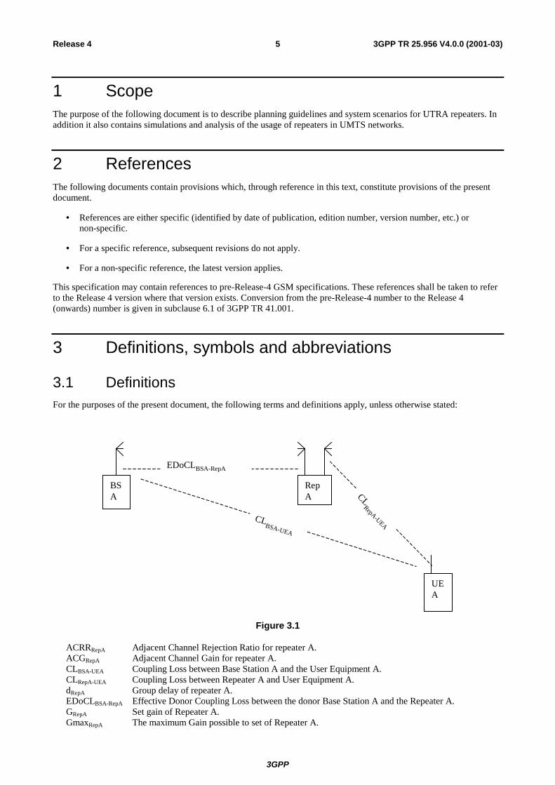
3.1 Definitions For the purposes of the present document, the following terms and definitions apply, unless otherwise stated:
BSA
RepA
UEA
EDoCLBSA-RepA
CLBSA-UEA
CLRepA-UEA
Figure 3.1
ACRRRepA Adjacent Channel Rejection Ratio for repeater A. ACGRepA Adjacent Channel Gain for repeater A. CLBSA-UEA Coupling Loss between Base Station A and the User Equipment A. CLRepA-UEA Coupling Loss between Repeater A and User Equipment A. dRepA Group delay of repeater A. EDoCLBSA-RepA Effective Donor Coupling Loss between the donor Base Station A and the Repeater A. GRepA Set gain of Repeater A. GmaxRepA The maximum Gain possible to set of Repeater A.
3GPP
3GPP TR 25.956 V4.0.0 (2001-03)6Release 4
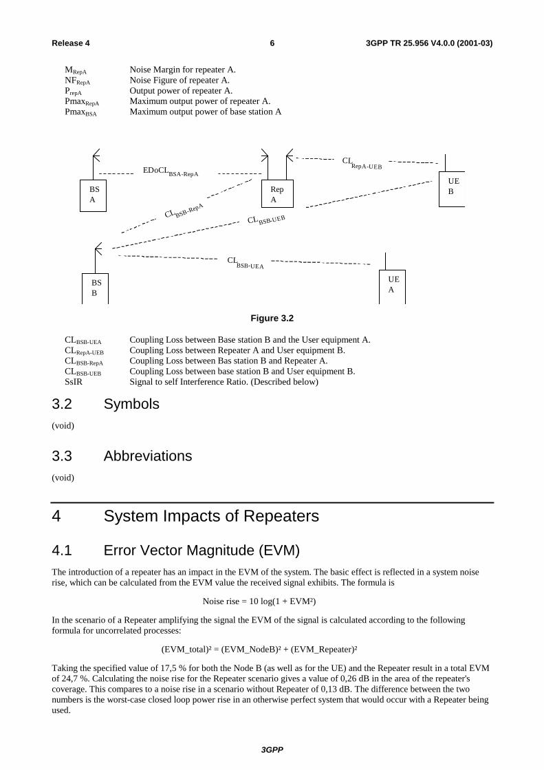
MRepA Noise Margin for repeater A. NFRepA Noise Figure of repeater A. PrepA Output power of repeater A. PmaxRepA Maximum output power of repeater A. PmaxBSA Maximum output power of base station A
BS A
UE A
EDoCL BSA-RepA
CL BSB-UEB
CL RepA-UEB
BS B
CL BSB-UEA
UEB Rep
A CL
BSB-RepA
Figure 3.2
CLBSB-UEA Coupling Loss between Base station B and the User equipment A. CLRepA-UEB Coupling Loss between Repeater A and User equipment B. CLBSB-RepA Coupling Loss between Bas station B and Repeater A. CLBSB-UEB Coupling Loss between base station B and User equipment B. SsIR Signal to self Interference Ratio. (Described below)
3.2 Symbols (void)
3.3 Abbreviations (void)
4 System Impacts of Repeaters
4.1 Error Vector Magnitude (EVM) The introduction of a repeater has an impact in the EVM of the system. The basic effect is reflected in a system noise rise, which can be calculated from the EVM value the received signal exhibits. The formula is
Noise rise = 10 log(1 + EVM²)
In the scenario of a Repeater amplifying the signal the EVM of the signal is calculated according to the following formula for uncorrelated processes:
(EVM_total)² = (EVM_NodeB)² + (EVM_Repeater)²
Taking the specified value of 17,5 % for both the Node B (as well as for the UE) and the Repeater result in a total EVM of 24,7 %. Calculating the noise rise for the Repeater scenario gives a value of 0,26 dB in the area of the repeater's coverage. This compares to a noise rise in a scenario without Repeater of 0,13 dB. The difference between the two numbers is the worst-case closed loop power rise in an otherwise perfect system that would occur with a Repeater being used.
3GPP
3GPP TR 25.956 V4.0.0 (2001-03)7Release 4
4.2 Peak Code Domain Error (PCDE) In the specification of the Peak Code Domain Error value of the Repeater –35 dB is used. The number for the Node B is –33dB. If we assume the processes in the Repeater that lead to the PCDE being independent of the equivalent process in the Node B we can assume that they can be treated as noise. In this case the resulting value for PCDE is calculated from the linear addition of the two signals that will lead to –31 dB. This is a 2 dB degradation to the value of the Node B. For the repeated cell the degradation might be negligible. In case of a neighbour cell the might be affected to some extend. Presumably the soft handover gain will be reduced by the tenth of a dB.
4.3 Frequency error The effect of the additional frequency error will be a reduction of the maximum speed. In the repeater core specification the minimum requirement on frequency stability is 0,01 ppm. Hence, with the 0,05 ppm minimum requirement for the base station frequency stability the resulting "worst case" for a signal that have been amplified by the repeater is 0,06 ppm.
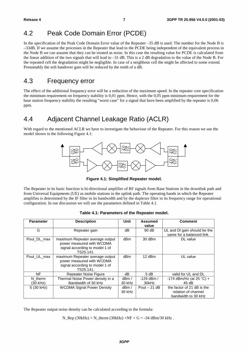
4.4 Adjacent Channel Leakage Ratio (ACLR) With regard to the mentioned ACLR we have to investigate the behaviour of the Repeater. For this reason we use the model shown in the following Figure 4.1:
Figure 4.1: Simplified Repeater model.
The Repeater in its basic function is bi-directional amplifier of RF signals from Base Stations in the downlink path and from Universal Equipments (UE) as mobile stations in the uplink path. The operating bands in which the Repeater amplifies is determined by the IF filter in its bandwidth and by the duplexer filter in its frequency range for operational configuration. In our discussion we will use the parameters defined in Table 4.1.
Table 4.1: Parameters of the Repeater model.
Parameter Description Unit Assumed value
Comment
G Repeater gain dB 90 dB UL and Dl gain should be the same for a balanced link.
Pout_DL_max maximum Repeater average output power measured with WCDMA signal according to model 1 of
TS25.141.
dBm 30 dBm DL value
Pout_UL_max maximum Repeater average output power measured with WCDMA signal according to model 1 of
TS25.141.
dBm 12 dBm UL value
NF Repeater Noise Figure dB 5 dB valid for UL and DL N_therm (30 kHz)
Thermal Noise Power density in a Bandwidth of 30 kHz
dBm / 30 kHz
-129 dBm / 30kHz
-174 dBm/Hz (at 25 °C) + 45 dB
S (30 kHz) WCDMA Signal Power Density dBm / 30 kHz
Pout – 21 dB the factor of 21 dB is the relation of channel
bandwidth to 30 kHz
The Repeater output noise density can be calculated according to the formula:
N_Rep (30kHz) = N_therm (30kHz) +NF + G = -34 dBm/30 kHz .
3GPP
3GPP TR 25.956 V4.0.0 (2001-03)8Release 4
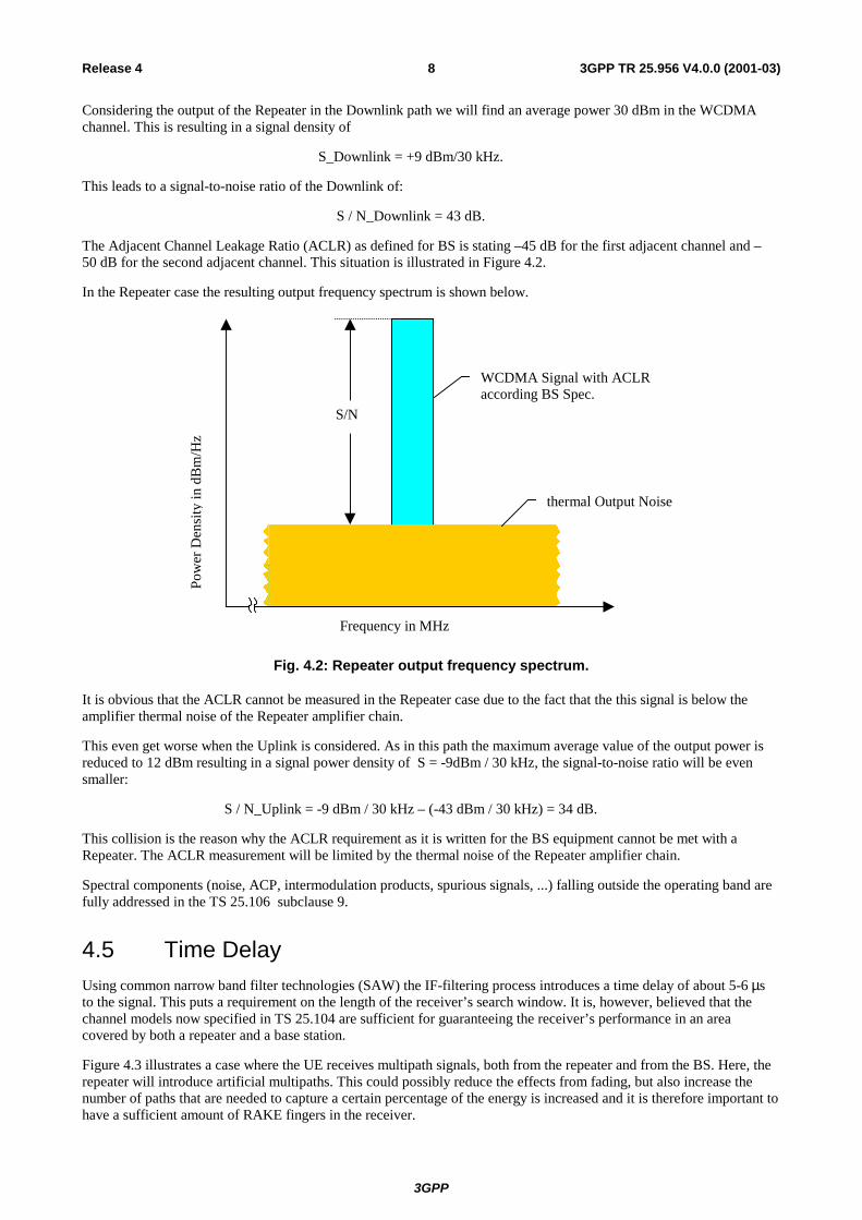
Considering the output of the Repeater in the Downlink path we will find an average power 30 dBm in the WCDMA channel. This is resulting in a signal density of
S_Downlink = +9 dBm/30 kHz.
This leads to a signal-to-noise ratio of the Downlink of:
S / N_Downlink = 43 dB.
The Adjacent Channel Leakage Ratio (ACLR) as defined for BS is stating –45 dB for the first adjacent channel and –50 dB for the second adjacent channel. This situation is illustrated in Figure 4.2.
In the Repeater case the resulting output frequency spectrum is shown below.
Pow
er D
ensi
ty in
dB
m/H
z
Frequency in MHz
thermal Output Noise
WCDMA Signal with ACLRaccording BS Spec.
S/N
Fig. 4.2: Repeater output frequency spectrum.
It is obvious that the ACLR cannot be measured in the Repeater case due to the fact that the this signal is below the amplifier thermal noise of the Repeater amplifier chain.
This even get worse when the Uplink is considered. As in this path the maximum average value of the output power is reduced to 12 dBm resulting in a signal power density of S = -9dBm / 30 kHz, the signal-to-noise ratio will be even smaller:
S / N_Uplink = -9 dBm / 30 kHz – (-43 dBm / 30 kHz) = 34 dB.
This collision is the reason why the ACLR requirement as it is written for the BS equipment cannot be met with a Repeater. The ACLR measurement will be limited by the thermal noise of the Repeater amplifier chain.
Spectral components (noise, ACP, intermodulation products, spurious signals, ...) falling outside the operating band are fully addressed in the TS 25.106 subclause 9.
4.5 Time Delay Using common narrow band filter technologies (SAW) the IF-filtering process introduces a time delay of about 5-6 µs to the signal. This puts a requirement on the length of the receiver’s search window. It is, however, believed that the channel models now specified in TS 25.104 are sufficient for guaranteeing the receiver’s performance in an area covered by both a repeater and a base station.
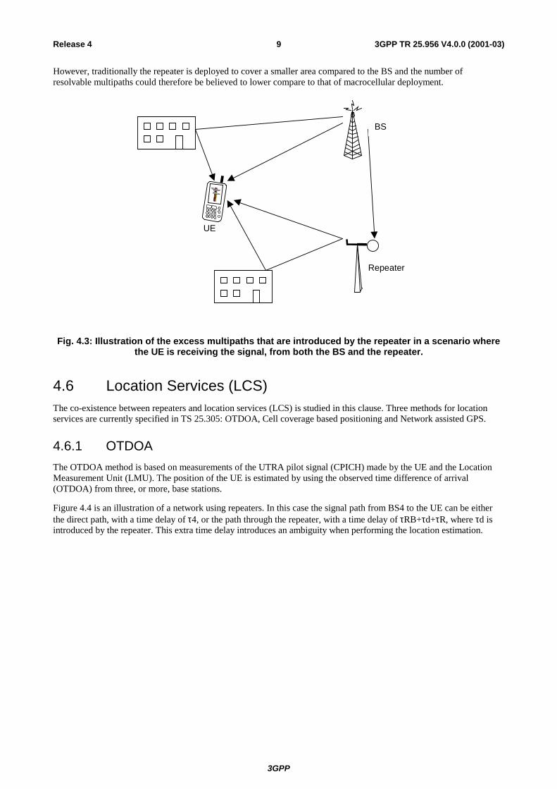
Figure 4.3 illustrates a case where the UE receives multipath signals, both from the repeater and from the BS. Here, the repeater will introduce artificial multipaths. This could possibly reduce the effects from fading, but also increase the number of paths that are needed to capture a certain percentage of the energy is increased and it is therefore important to have a sufficient amount of RAKE fingers in the receiver.
3GPP
3GPP TR 25.956 V4.0.0 (2001-03)9Release 4
However, traditionally the repeater is deployed to cover a smaller area compared to the BS and the number of resolvable multipaths could therefore be believed to lower compare to that of macrocellular deployment.
UE
Repeater
BS
Fig. 4.3: Illustration of the excess multipaths that are introduced by the repeater in a scenario where the UE is receiving the signal, from both the BS and the repeater.
4.6 Location Services (LCS) The co-existence between repeaters and location services (LCS) is studied in this clause. Three methods for location services are currently specified in TS 25.305: OTDOA, Cell coverage based positioning and Network assisted GPS.
4.6.1 OTDOA The OTDOA method is based on measurements of the UTRA pilot signal (CPICH) made by the UE and the Location Measurement Unit (LMU). The position of the UE is estimated by using the observed time difference of arrival (OTDOA) from three, or more, base stations.
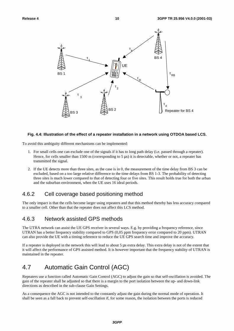
Figure 4.4 is an illustration of a network using repeaters. In this case the signal path from BS4 to the UE can be either the direct path, with a time delay of τ4, or the path through the repeater, with a time delay of τRB+τd+τR, where τd is introduced by the repeater. This extra time delay introduces an ambiguity when performing the location estimation.
3GPP
3GPP TR 25.956 V4.0.0 (2001-03)10Release 4
BS 4
BS 1
BS 2
τ 1
τ 2
τ4
Repeater for BS 4
τ R
τ d
τ RB
BS 3
τ3
UE
Fig. 4.4: Illustration of the effect of a repeater installation in a network using OTDOA based LCS.
To avoid this ambiguity different mechanisms can be implemented:
1. For small cells one can exclude one of the signals if it has to long path delay (i.e. passed through a repeater). Hence, for cells smaller than 1500 m (corresponding to 5 µs) it is detectable, whether or not, a repeater has transmitted the signal.
2. If the UE detects more than three sites, as the case is in 0, the measurement of the time delay from BS 3 can be excluded, based on a too large relative difference to the time delays from BS 1-3. The probability of detecting three sites is much lower compared to that of detecting four or five sites. This result holds true for both the urban and the suburban environment, when the UE uses 16 ideal periods.
4.6.2 Cell coverage based positioning method The only impact is that the cells become larger using repeaters and that this method thereby has less accuracy compared to a smaller cell. Other than that the repeater does not affect this LCS method.
4.6.3 Network assisted GPS methods The UTRA network can assist the UE GPS receiver in several ways. E.g. by providing a frequency reference, since UTRAN has a better frequency stability compared to GPS (0,05 ppm frequency error compared to 20 ppm). UTRAN can also provide the UE with a timing reference to reduce the UE GPS search time and improve the accuracy.
If a repeater is deployed in the network this will lead to about 5 µs extra delay. This extra delay is not of the extent that it will affect the performance of GPS assisted method. It is however important that the frequency stability of UTRAN is maintained in the repeater.
4.7 Automatic Gain Control (AGC) Repeaters use a function called Automatic Gain Control (AGC) to adjust the gain so that self-oscillation is avoided. The gain of the repeater shall be adjusted so that there is a margin to the port isolation between the up- and down-link directions as described in the sub-clause Gain Settings.
As a consequence the AGC is not intended to the constantly adjust the gain during the normal mode of operation. It shall be seen as a fall back to prevent self-oscillation if, for some reason, the isolation between the ports is reduced
3GPP
3GPP TR 25.956 V4.0.0 (2001-03)11Release 4
compared to the isolation measured during the deployment or an increase in input power to a level larger than the input level creating the maximum output power.
The AGC is also slow in comparison to the fast power control (the range of several microseconds) in order not to interfere with the system performance. The AGC should further adjust the gain in both the up and downlink in order to make the repeater a transparent system element.
5 Planning with Repeaters
5.1 Sole System
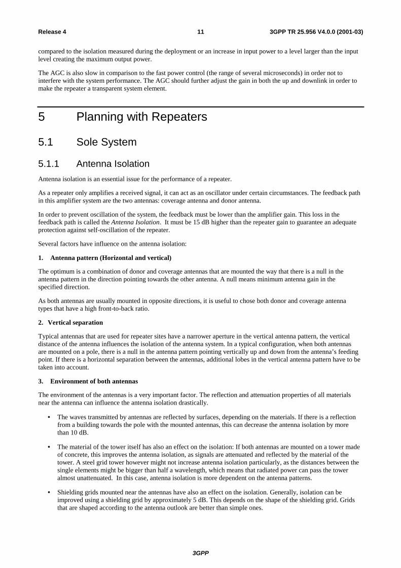
5.1.1 Antenna Isolation Antenna isolation is an essential issue for the performance of a repeater.
As a repeater only amplifies a received signal, it can act as an oscillator under certain circumstances. The feedback path in this amplifier system are the two antennas: coverage antenna and donor antenna.
In order to prevent oscillation of the system, the feedback must be lower than the amplifier gain. This loss in the feedback path is called the Antenna Isolation. It must be 15 dB higher than the repeater gain to guarantee an adequate protection against self-oscillation of the repeater.
Several factors have influence on the antenna isolation:
1. Antenna pattern (Horizontal and vertical)
The optimum is a combination of donor and coverage antennas that are mounted the way that there is a null in the antenna pattern in the direction pointing towards the other antenna. A null means minimum antenna gain in the specified direction.
As both antennas are usually mounted in opposite directions, it is useful to chose both donor and coverage antenna types that have a high front-to-back ratio.
2. Vertical separation
Typical antennas that are used for repeater sites have a narrower aperture in the vertical antenna pattern, the vertical distance of the antenna influences the isolation of the antenna system. In a typical configuration, when both antennas are mounted on a pole, there is a null in the antenna pattern pointing vertically up and down from the antenna’s feeding point. If there is a horizontal separation between the antennas, additional lobes in the vertical antenna pattern have to be taken into account.
3. Environment of both antennas
The environment of the antennas is a very important factor. The reflection and attenuation properties of all materials near the antenna can influence the antenna isolation drastically.
• The waves transmitted by antennas are reflected by surfaces, depending on the materials. If there is a reflection from a building towards the pole with the mounted antennas, this can decrease the antenna isolation by more than 10 dB.
• The material of the tower itself has also an effect on the isolation: If both antennas are mounted on a tower made of concrete, this improves the antenna isolation, as signals are attenuated and reflected by the material of the tower. A steel grid tower however might not increase antenna isolation particularly, as the distances between the single elements might be bigger than half a wavelength, which means that radiated power can pass the tower almost unattenuated. In this case, antenna isolation is more dependent on the antenna patterns.
• Shielding grids mounted near the antennas have also an effect on the isolation. Generally, isolation can be improved using a shielding grid by approximately 5 dB. This depends on the shape of the shielding grid. Grids that are shaped according to the antenna outlook are better than simple ones.
3GPP
3GPP TR 25.956 V4.0.0 (2001-03)12Release 4
5.1.2 Coupling loss measurements The links of most the interest are the coupling loss between the Node B (Base Station = BS) and the repeater and at the repeater between the donor- and the coverage antenna.
1. Coupling loss between the Node B and the repeater.
1) Connect a Measurement User Equipment to the donor antenna and measure the incoming pilot signal.
2) The coupling loss between Node B and the repeater is then calculated as
CL = BS Pilot Level output power [dBm] – Measured input power at the Measurement User Equipment [dBm].
2. Coupling loss at the repeater between the donor- and the coverage antenna.
1) Connect the input of a spectrum analyser to the donor antenna cable
2) Set up the instrument for the desired UMTS band.
3) Connect a signal generator to the coverage antenna cable of the repeater.
4) Set up the analyser for the highest possible sensitivity (more than –100dBm) for 0 dBm source-power.
5) Set the analyser to “max-hold” if you do not use a tracking generator.
6) Set the output-power of the generator to 0 dBm.
7) Start sweeping
8) The minimum isolation is the highest value of the curve (except carriers transmitted by surrounding BS). (Note the highest value for further use.)
9) Change measurement-ports to check for the opposite direction by repeating the measurement procedure. (Note the worst value of isolation for further use.)
5.1.3 Gain Settings Considering the repeater application in an isolated UMTS system, the basic rule as described above applies for both up-link and down-link:
GrepA ≤ Repeater port isolation – 15 dB
For the down-link the following rule of thumb ensures that the repeater AGC (Automatic Gain Control) is not activated during normal traffic conditions.
G ≤ PmaxRepA + EDoCLBSA-RepA – PmaxBSA
In cell planning, the repeater can be modelled as a base station with transmit power
PRepA = PBSA – EDoCLBSA-RepA + GRepA (dBm)
For the up-link, the repeater has a transferred sensitivity;
SensitivityRepA = SensitivityBSA - (EDoCLBSA-RepA - GRepA) (dBm)
The transferred sensitivity is controlled by the setting the repeater gain in relation to the effective donor coupling loss. It is recommended that the transferred sensitivity is approximately (5 to 10) + NfrepA dB less than the donor base station sensitivity, in order not to desensitise the base station. This rule can be adjusted in the case where the repeater coverage area is also the main coverage area of the base station. The term “noise margin”, M, is introduced to describe the difference between the base station sensitivity and the transferred repeater sensitivity in the installation.
MRepA = EDoCLBSA-RepA - GRepA (dB)
The gain should be set so that the link balance through the repeater path is the same as the link balance in the donor base station. The loss of diversity gain may here be considered.
3GPP
3GPP TR 25.956 V4.0.0 (2001-03)13Release 4
5.1.4 Delay The UTRA BS and UEs can handle a 20 µs time delay between two paths (c.f. TS 25.101 and TS 25.104). The repeater introduces a time delay of 5-6 µs. The signal paths introduced through the repeater will be longer than the direct path, both due to the extra travelling distance required for the signal (approximately 5 µs per 1.5 km) and due to the group delay in the repeater itself.
For outdoor repeater coverage, where the areas can be substantial, it is a rule of thumb that the repeater site should be placed between the repeater service area and the donor base station.
For applications with donor signal provided via optical fibre, it should be noted that the speed of light in fibres is approximately 2/3 of that in vacuum, or 5 µs per km. This may introduce extra delay to be considered when designing both indoor and outdoor repeater applications.
5.2 Co-existence with UTRA FDD
5.2.1 Out of band gain In the UTRA repeater core specification TS 25.106 the out of band requirement have been derived assuming an in-band gain of 90 dB. The rationale for this value was the common understanding that it represents a maximum gain value for UTRA repeaters and that UTRA repeaters with higher value are very unlikely. In most application the repeater gain may be adjusted to lower values.
With a reduction of the in-band gain value, compared to the assumed 90 dB, the out of band gain values, which decides the adjacent channel gain (ACG) will also be reduced compared to the values occurring in the specification TS 25.106.
5.2.2 Isolation Taking other operator systems into concern, it is the responsibility of the repeater operator to make sure that the repeater installation does not significantly alter the cellular design of the uncoordinated operator.
In the case where a repeater is installed in the vicinity of a base station operating on the adjacent channel the required isolation between base station B and the repeater’s donor port will depend on the up-link gain. It can be seen that the signal from UEB to BSB can take the two paths “directly” or “via repeater A”, both of which comprise multi-paths. It is here assumed that the path through the repeater will be badly distorted, since the delay spread in the adjacent carrier frequencies are bound to be substantial. As a consequence, the signal travelled through the repeater is considered to be interference only. However, this interference will have a fixed relation to the signal power from UEB arriving in BSB since it follows the power control applied from BSB on UEB.
The term “self-interference”, is here introduced to describe this phenomenon. SsIR (Signal to self Interference Ratio) is the relation between the power level of the distorted UEB signal from the repeater A path and the undistorted signal arriving direct from the UE, taken on the BSB receiver terminal. The effect of putting the SsIR to 0 dB is that a UEB with this SsIR occupies twice the air interface capacity from BSB as required from a UE with infinite SsIR utilising the same service.
Now, in order to ensure the stability of system B a proper SsIR must be set, resulting in a minimum requirement for the isolation between the repeater A donor port and the base station B receive port:
CLBSB-RepA ≥ SsIR + ACGRepA – CLminRepA-UEA + CLBSB-UEB (dB)
It is here assumed that the UE of system A and the UE if system B can enter the same areas and hence
CLRepA-UEA = CLRepA-UEB.
The CLminRepA-UEA is the minimum Coupling loss that can be experienced between the repeater and the UE. It is assumed that the coupling loss between the repeater and an UE in the repeater service area will vary more than the coupling loss between BSB and the same UE. CLBSB-UEB is taken where CLminRepA-UEA occurs.
The ACGRepA can be calculated as the gain set in repeater A minus the repeater’s Adjacent Channel Rejection Ratio (ACRR). The ACRR of the repeater can be estimated as the maximum gain that can be set in the repeater minus the adjacent channel maximum gain as stated in TS. 25.106,section 8.1, unless otherwise stated by the repeater manufacturer. E.g. the gain of 90 dB assumed as GmaxrepA renders the ACRRrepA of 37 dB according to TS 25.106.
3GPP
3GPP TR 25.956 V4.0.0 (2001-03)14Release 4
The above described formulae for CLBSB-RepA do not take into account the absolute power and spurious emission requirements put forward in TS 25.106, section 9.1. The required coupling losses between the repeater's donor port and base station B are derived using the unwanted emission requirements in the first adjacent channel (TS 25.106 section 9.1.1):
For PmaxRepA ≥ +39 dBm;
CLBSB-RepA ≥ 105 dB
For +31 dBm ≤ PmaxRepA < +39 dBm;
CLBSB-RepA (dB) ≥ PmaxRepA (dBm) + 66 dB
For PmaxRepA < +31 dBm;
CLBSB-RepA ≥ 97 dB
The required coupling losses are calculated according to the requirement that the spurious emission level does not exceed -126 dBm/100 kHz at base station B's receive port (corresponding to spurious emission requirement for co-located BS, c.f. TS 25.104 and a 30 dB MCL, c.f. TR 25.942). Normal up-link powers are in the range of 0 dBm - 20 dBm.
In the downlink direction the UTRA repeater specification TS 25.106 includes additional requirement on spurious emission for the protection of co-located UTRA FDD BS receivers. If these additional requirements are applied, the isolation between the coverage antenna and the base station antennas should be more than 30 dB.
Given the above recommendations, the coverage antenna should be put closer to the BS antennas than the donor antenna should where repeaters are co-sitting with UMTS FDD base stations. The isolation required between the donor antenna and the service antenna will generate the isolation required between the donor antenna and the co-sited base station antenna. It is also recommended to use a high gain donor antenna with narrow horizontal beam width so that the UL power is directed exclusively towards the donor BS.
5.2.2.1 Example on application of equations
Assume an area where two UMTS operators, A and B, are using adjacent RF-channels.
Operator A wants to put a repeater in a position in the area. The coupling loss between the repeater donor port and the donor BS is measured to be 100 dB (using a UE from operator A connected to the antenna feeder to be connected to the repeater donor port.) Applying a noise margin of 10 dB, the repeater gain is set to 90 dB. The service antenna is mounted so that the repeater antenna isolation requirements are fulfilled.
The minimum coupling loss between a UE A and the repeater service port is measured to be 70 dB (total coupling loss through the repeater is measured to be 80 dB, and hence the coupling loss between the repeater and the UE is less by the set noise margin). A UE from operator B is used to measure the coupling loss between the UEB and the BSB in this point. The result is 100 dB coupling loss. The Adjacent channel rejection ratio is estimated to be 37 dB as described above. The SsIR at this point is set to 0 dB (implying that it will be lower every where else), and hence the minimum required coupling loss between the repeater donor port and the BS B is calculated to be 83 dB. The coupling loss between the BS B and the repeater donor port can be verified by connecting the UE B to the donor antenna feeder at the repeater site and measuring it.
5.3 Co-existence with UTRA TDD
5.3.1 Isolation In the downlink direction the UTRA FDD repeater specification TS 25.106 includes additional requirement on spurious emission for the protection of co-existence with UTRA TDD. If these additional requirements are applied, the isolation between the coverage antenna and the base station antennas should be more than 30 dB.
For the donor antenna, the repeater should have the same coupling loss values to the BS as described in the section above.
3GPP
3GPP TR 25.956 V4.0.0 (2001-03)15Release 4
5.4 Co-existence with GSM 900 and/or DCS 1800
5.4.1 Isolation Co-existence and co-siting with GSM 900 and/or DCS 1800 is addressed in the UTRA repeater performance specification where additional requirements exist for these scenarios.
If these additional requirements are applied, the isolation between the coverage antenna or donor and the base station antennas should be more than 30 dB.
5.5 Environments with low minimum coupling loss (MCL) This section addresses the use of and planning with repeaters in environments with a Minimum Coupling Loss (MCL) of 40 dB. The cases are studied, one where the repeater's parameters are intended for general applications and one where they have been changed to align with the MCL value investigated. In the examples below "A" indicate the channel being amplified by the repeater and "B" the service at the adjacent channel.
5.5.1 Normal repeater parameters The following parameters are seen to represent a repeater intended for normal applications; P_max_DL (maximum power down-link) = 30 dBm P_max_UL (maximum power up-link) = 12 dBm (the value can be reduced with respect to the Downlink due to the uplink power control mechanism) G (gain, common for both directions) = 90 dB NF (noise figure) = 5 dB
The coupling loss between the repeater and the base station is 100 dB and the output power of 30 dBm is thus the result of a 40 dBm BS output power.
If we now investigate the maximum received power for UEA we find that:
P_received_max_UEA = 30 dBm (P_max_DL) - 40 dB (MCL) = -10 dBm.
This value is 15 dB greater that the minimum requirements on the maximum UE received power of -25 dBm (TS 25.101) and hence quality degradation or dropped calls can be expected.
Further, the down-link interference at UEB due to the UE's Adjacent Channel Selectivity (ACS) can be calculated by using the 33 dB ACS value given in TS 25.101:
I_UEB = 30 dBm (P_max_DL) - 40 dB (MCL) -33 dB (ACS) = -43 dBm.
This interference level is clearly to great in comparison to the signal levels that can be expected on down-link of service B. As a consequence quality degradation or dropped calls can be expected.
In conclusion it can be stated that a the usage of a repeater with normal parameters setting (given above) will result in dropped calls on the down-link, both the operator installing the repeater as well as operators at adjacent channels, when used in an environment with a 40 dB MCL. This should hence be avoided.
5.5.2 Repeater parameters adjusted to low MCL To function in an environment with a 40 dB MCL the maximum output power in the down-link of the repeater have to be adjusted so that the maximum UE received power does not exceed -25 dBm. This lead to the following set of parameters: P_max_DL (maximum power down-link) = 15 dBm P_max_UL (maximum power up-link) = -3 dBm (the difference between UL and DL is kept as in section 5.5.1) G (repeater gain, common for both directions) = 72 dB (the gain is given considering the coupling loss to the BSA) NF (noise figure) = 5 dB
With a 15 dBm maximum down-link output power, the down-link interference for UEB due to the UE's Adjacent Channel Selectivity (ACS) can be calculated by using the 33 dB ACS value given in TS 25.101:
3GPP
3GPP TR 25.956 V4.0.0 (2001-03)16Release 4
I_UEB = 15 dBm (P_max_DL) - 40 dB (MCL) -33 dB (ACS) = -58 dBm.
This interference level is fairly large and might cause quality degradation or dropped calls, but is a value in the range that can be expected if a UE is in the vicinity of other operators base stations or repeaters. To study the up-link interference generated by the repeaters out of band gain the minimum and maximum UE output is used. Further, the out of band values specified in the repeater core specification TS 25.106 are based on a 90 maximum gain value. By back calculation the Adjacent Channel Rejection Ratio (ACRR) of the filters in the repeater can be calculated to be 37 dB. Hence, if the in-band gain of the repeater is lower compared to the assumed 90 dB the out of band gain will be reduced accordingly.
If UEB is transmitting at minimum output power the up-link interference at BSB can be calculated as:
I_BSB = -50 dBm (P_min_UE) - 40 dB (MCL) + 72 dB (G) -37 dB (ACRR) - 100 dB (CLBSB-Rep) = -155 dBm.
This value is very low compared to the thermal noise of the BS and can hence have no impact on the sensitivity.
To study the case when the UEB is transmitting at maximum output power we first study the power received in the repeaters operating band. This is calculated using the UE ACLR of 33 dB (according to TS 25.101 V3.4.0). In the repeater specification TS 25.106 there are requirements on the Automatic Gain Control (AGC), this functionality ensure that the amplifiers of the repeater is not driven into saturation by lowering the gain if a high input signal is applies.
Now, with the maximum output power in the repeaters up-link of -3 dBm the reduction of the gain in the operating band can be calculated as:
G = -3 dBm (P_max_UL) -21 dBm (P_max_UE) + 40 (MCL) + 33 (UE ACLR) = 49 dB.
With this new value of the repeaters gain the up-link interference given as:
I_BSB = 21 dBm (P_max_UE) - 40 dB (MCL) + 49 dB (G) -37 dB (ACRR) - 100 dB (CLBSB-Rep) = -107 dBm
a value which is 5 dB below the thermal noise floor of the BS resulting in sensitivity degradation of about 1 dB.
The maximum power from UEA at BSA has been reduced due to impact of UEBs ACLR on the repeater's gain. The resulting value would be:
P_max_received_BSA = 21 dBm (P_max_UE) - 40 dB (MCL) + 49 dB (G) -100 dB (CLBSB-Rep) = -70 dBm.
However, this value is still far greater than the maximum uplink power can deliver but also a much greater level than what is needed at the BS. Also, with BS reference sensitivity of -121 dBm the resulting transferred sensitivity and the repeater is calculated as:
SensitivityRepA = -121 dBm (BS sensitivity) + 100 dB (CLBSB-Rep) - 49 dB (G) = -70 dBm.
The conclusion is that by an adjustment of the repeater parameters to a MCL of 40 dB the co-existence problems are mitigated. However, due to the UE ACLR impact on the repeater gain it is recommended that care be taken so that the installation results in a MCL greater than 40 dB. With a high MCL value the operator can ensure that repeaters coverage area is maintained when UEs from adjacent channels are in the close proximity.
5.6 Analysis of out of band gain in the 3rd adjacent channel
5.6.1 MCL=70 dB In this case following parameters are seen to represent a repeater intended for normal applications and typical coupling loss values;
Pmax_DLrep (maximum power down-link) = 30 dBm.
Pmax_ULrep (maximum power up-link) = 12 dBm (the value can be reduced 18 dB with respect to the Downlink due to the uplink power control mechanism).
G_maxrep (maximum repeater Gain, common for both directions) = 90 dB.
CLBSB-Rep (Coupling loss between repeater and base station B) = 100 dB.
3GPP
3GPP TR 25.956 V4.0.0 (2001-03)17Release 4
MCLUEB-rep (Mutual Coupling Loss between the repeater and the UEB) = 70 dB.
ACG3rep (Adjacent Channel Gain in the 3rd adjacent channel) = 35 dB.
ACCR3rep (Adjacent Channel Rejection Ratio in the 3rd adjacent channel) = G_maxrepeater - ACG3rep = 55 dB.
In addition the following parameters are used in the analysis:
P_maxUEB (UEB maximum UL power, operating at a frequency corresponding to the repeaters 3rd adjacent channel)= 21 dBm.
ACS3UEB (the UE’s selectivity in the 3rd adjacent channel)= 52 dB
P_maxBSB (BS B maximum DDL power) = 40 dBm.
Up-link interference:
Under the assumption that the signal amplified by the repeater outside of the operating band is interference, the resulting level at the base station can be calculated as
I_ULBSB = 21 dBm (P_maxUEB) - 70 dB (MCLUEB-rep) + 90 dB (G_maxrep) - 55 dB (ACCR3rep)- 100 dB (CLBSB-Rep) = -114 dBm.
Down-link interference:
In the analysis of down-link interference, we compare the interference generated by the repeater's out of band gain (referred to ACG) to that caused by the UE's blocking sensitivity (ACS), where the values have been obtained with back calculations from TS 25.101:
I_DLUEB (ACG) = 40 dBm (P_maxBSB) -100 dB (CLBSB-Rep) + 35 dB (ACG3rep) - 100 dB (CLBSB-Rep) = -95 dBm.
I_DLUEB (ACS)= 30 dBm (Pmax_DLrep) -70 dB (MCL) -52 dB (ACS3UEB) = -92 dBm.
I_DLUEB (ACG+ACS) = -90,2 dBm
I.e. the additional interference generated by the repeater's out of band gain is 1,8 dB.
5.6.2 MCL=40 dB In this case the repeater's output power and gain is adjusted to a 40 dB MCL leading to the following;
Pmax_DLrep (maximum power down-link) = 15 dBm.
Pmax_ULrep (maximum power up-link) = -3 dBm.
Grep (Gain, common for both directions) = 75 dB.
CLBSB-Rep = 100 dB.
MCLrep-UEB = 40 dB.
ACG3rep = 75 dB (Grep) - 55 dB (ACRR3rep) = 20 dB.
In addition the following parameters are used in the analysis:
PmaxUEB (operating at a frequency corresponding to the repeaters 3rd adjacent channel) = 21 dBm.
ACS3UEB (the UEs selectivity in the 3rd adjacent channel) = 52 dB
P_maxBSB = 40 dBm.
Up-link interference:
With a 40 dB MCLrep-UEB the repeater's gain is reduced by the repeater AGC due to the UEB's unwanted emission. The new inband gain level can be calculated as
3GPP
3GPP TR 25.956 V4.0.0 (2001-03)18Release 4
G_newrep = -3 dBm (Pmax_ULrep) - -23 dBm (Pspur.maxUEB) + 40 (MCLrep-UEB) = 60 dB,
i.e. a reduction with 15 dB compared to the original settings.
Using this new inband gain level we calculate the up-link interference as:
I_ULBSB = 21 dBm (PmaxUEB) - 40 dB (MCLrep-UEB) + 60 (G_newrep)
- 55 dB (ACCR3rep) - 100 dB (CLBSB-Rep) = -113 dBm.
Down-link interference:
I_DLUEB (ACG) = 40 dBm (PmaxBSB) -100 dB (CLBSB-Rep) + 60 dB (G_newrep) - 55 dB (ACCR3rep) - 40 dB (MCLrep-UEB) = -95 dBm.
I_DLUEB (ACS)= 15 dBm (Pmax_DL rep) -40 dB (MCLrep-UEB) -52 dB (ACS3UEB) = -77 dBm.
I_DLUEB (ACG+ACS) = -77 dBm.
As seen the interference caused by the repeater's out of band gain can be neglected compared to that caused by the UE's selectivity.
6 System Simulations and Analysis
6.1 Down-link co-existence simulations This section is intended to analyse a co-existence scenario between a UTRA repeaters and UTRA services at adjacent channels.
Consider two operators (Operator A and B) that have base stations operating at adjacent frequencies located in the vicinity of each other and with equal EIRP. Further, consider also a down link macro scenario where the signal level is insufficient near the border of the cell, and one of the operators (Operator A) places a repeater there to strengthen the signal.
When there are no ideal filters or amplifiers available, the signal in the repeater will leak into the adjacent channel and causing an area around the repeater site with increased interference in the adjacent frequency.
The interference on frequency B at the repeater in this scenario consists of four components:
1. The out of band emission from operator A' base station that is also amplified by the repeaters adjacent channel gain (ACG).
2. The signals from operator B' base station that is amplified by the repeaters ACG. In the analysis this signal is treated as interference.
3. The out of band emission produced by the repeater.
4. The interference caused by the adjacent channel selectivity (ACS) in the receiving mobile.
Hence, the effect of the three first (1-3) interference components are caused by the repeater' ACG and out of band emission, and the last one by the filter in the mobile station.
The simulations is based on a macro path loss model describe in TS 25.942 "RF Scenarios". Though this model has its limitations in the vicinity of the transmitter, it indicates how large the outage zone will be. The simulation assumptions are described in the Appendix. The repeater is placed at a distance of 1.5 km with a donor antenna that has LOS conditions to the base station. The coupling loss to the repeater is 100 dB and with 90 dB gain the output power is 33 dBm.
In the results below the outage zone is defined as the area, where SIR < -8 dB.
3GPP
3GPP TR 25.956 V4.0.0 (2001-03)19Release 4
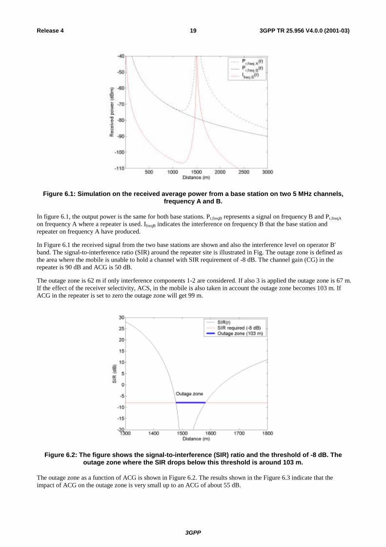
Figure 6.1: Simulation on the received average power from a base station on two 5 MHz channels, frequency A and B.
In figure 6.1, the output power is the same for both base stations. Pr,freqB represents a signal on frequency B and Pr,freqA on frequency A where a repeater is used. IfreqB indicates the interference on frequency B that the base station and repeater on frequency A have produced.
In Figure 6.1 the received signal from the two base stations are shown and also the interference level on operator B' band. The signal-to-interference ratio (SIR) around the repeater site is illustrated in Fig. The outage zone is defined as the area where the mobile is unable to hold a channel with SIR requirement of -8 dB. The channel gain (CG) in the repeater is 90 dB and ACG is 50 dB.
The outage zone is 62 m if only interference components 1-2 are considered. If also 3 is applied the outage zone is 67 m. If the effect of the receiver selectivity, ACS, in the mobile is also taken in account the outage zone becomes 103 m. If ACG in the repeater is set to zero the outage zone will get 99 m.
Figure 6.2: The figure shows the signal-to-interference (SIR) ratio and the threshold of -8 dB. The outage zone where the SIR drops below this threshold is around 103 m.
The outage zone as a function of ACG is shown in Figure 6.2. The results shown in the Figure 6.3 indicate that the impact of ACG on the outage zone is very small up to an ACG of about 55 dB.
3GPP
3GPP TR 25.956 V4.0.0 (2001-03)20Release 4
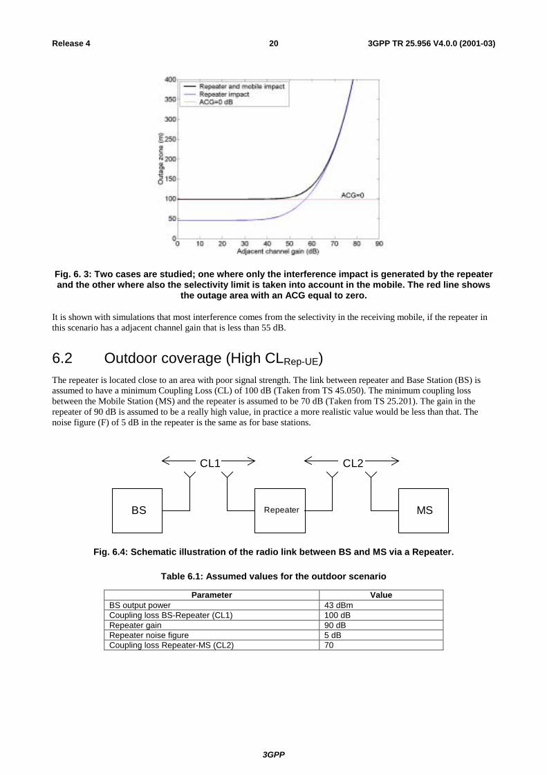
Fig. 6. 3: Two cases are studied; one where only the interference impact is generated by the repeater and the other where also the selectivity limit is taken into account in the mobile. The red line shows
the outage area with an ACG equal to zero.
It is shown with simulations that most interference comes from the selectivity in the receiving mobile, if the repeater in this scenario has a adjacent channel gain that is less than 55 dB.
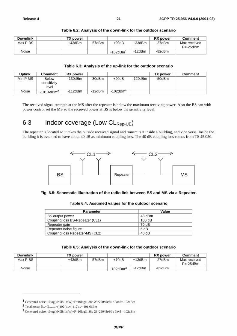
6.2 Outdoor coverage (High CLRep-UE) The repeater is located close to an area with poor signal strength. The link between repeater and Base Station (BS) is assumed to have a minimum Coupling Loss (CL) of 100 dB (Taken from TS 45.050). The minimum coupling loss between the Mobile Station (MS) and the repeater is assumed to be 70 dB (Taken from TS 25.201). The gain in the repeater of 90 dB is assumed to be a really high value, in practice a more realistic value would be less than that. The noise figure (F) of 5 dB in the repeater is the same as for base stations.
BS Repeater MS
CL1 CL2
Fig. 6.4: Schematic illustration of the radio link between BS and MS via a Repeater.
Table 6.1: Assumed values for the outdoor scenario
Parameter Value BS output power 43 dBm Coupling loss BS-Repeater (CL1) 100 dB Repeater gain 90 dB Repeater noise figure 5 dB Coupling loss Repeater-MS (CL2) 70
3GPP
3GPP TR 25.956 V4.0.0 (2001-03)21Release 4
Table 6.2: Analysis of the down-link for the outdoor scenario
Downlink TX power RX power Comment Max P BS +43dBm -57dBm +90dB +33dBm -37dBm Max received
P=-25dBm Noise -102dBm1 -12dBm -82dBm
Table 6.3: Analysis of the up-link for the outdoor scenario
Uplink: Comment RX power TX power Comment Min P MS Below
sensitivity level
-130dBm -30dBm +90dB -120dBm -50dBm
Noise -101.6dBm2 -112dBm -12dBm -102dBm1
The received signal strength at the MS after the repeater is below the maximum receiving power. Also the BS can with power control set the MS so the received power at BS is below the sensitivity level.
6.3 Indoor coverage (Low CLRep-UE) The repeater is located so it takes the outside received signal and transmits it inside a building, and vice versa. Inside the building it is assumed to have about 40 dB as minimum coupling loss. The 40 dB coupling loss comes from TS 45.050.
BS Repeater MS
CL1 CL2
Fig. 6.5: Schematic illustration of the radio link between BS and MS via a Repeater.
Table 6.4: Assumed values for the outdoor scenario
Parameter Value BS output power 43 dBm Coupling loss BS-Repeater (CL1) 100 dB Repeater gain 70 dB Repeater noise figure 5 dB Coupling loss Repeater-MS (CL2) 40 dB
Table 6.5: Analysis of the down-link for the outdoor scenario
Downlink TX power RX power Comment Max P BS +43dBm -57dBm +70dB +13dBm -27dBm Max received
P=-25dBm Noise -102dBm3 -12dBm -82dBm
1 Generated noise: 10log(kN0B/1mW)+F=10log(1.38e-23*290*5e6/1e-3)+5=-102dBm 2 Total noise: Nbs+Nrepeater=(-1021)lin+(-112)lin=-101.6dBm 3 Generated noise: 10log(kN0B/1mW)+F=10log(1.38e-23*290*5e6/1e-3)+5=-102dBm
3GPP
3GPP TR 25.956 V4.0.0 (2001-03)22Release 4
Table 6.6: Analysis of the up-link for the indoor scenario
Uplink: Comment RX power TX power Comment Min P MS -120dBm -20dBm +70dB -90dBm -50dBm
Noise -102dBm4 -132dBm -32dBm -102dBm1
6.4 Repeater up-link co-existence simulations
6.4.1 General This section analyses an up-link co-existence scenario between a UTRA repeaters and UTRA services at adjacent channels. Simulations are performed to analyse the effect of the interference generated by the repeater's out of band gain on services at adjacent channel.
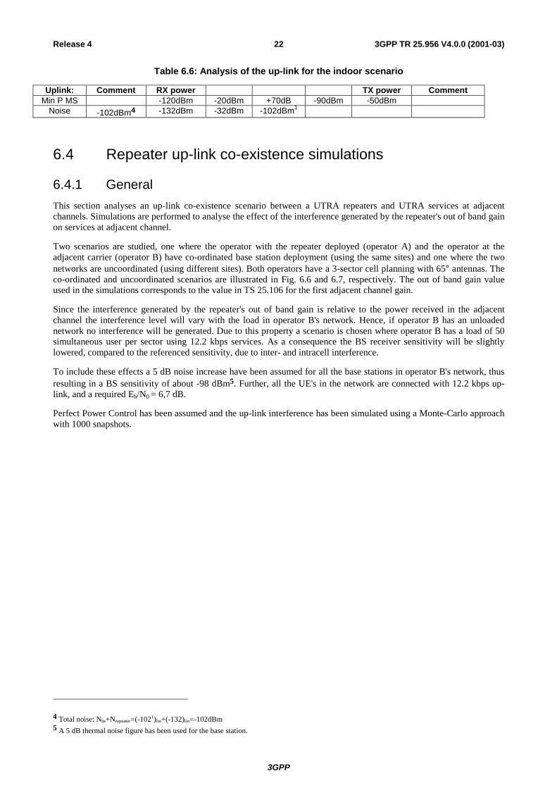
Two scenarios are studied, one where the operator with the repeater deployed (operator A) and the operator at the adjacent carrier (operator B) have co-ordinated base station deployment (using the same sites) and one where the two networks are uncoordinated (using different sites). Both operators have a 3-sector cell planning with 65° antennas. The co-ordinated and uncoordinated scenarios are illustrated in Fig. 6.6 and 6.7, respectively. The out of band gain value used in the simulations corresponds to the value in TS 25.106 for the first adjacent channel gain.
Since the interference generated by the repeater's out of band gain is relative to the power received in the adjacent channel the interference level will vary with the load in operator B's network. Hence, if operator B has an unloaded network no interference will be generated. Due to this property a scenario is chosen where operator B has a load of 50 simultaneous user per sector using 12.2 kbps services. As a consequence the BS receiver sensitivity will be slightly lowered, compared to the referenced sensitivity, due to inter- and intracell interference.
To include these effects a 5 dB noise increase have been assumed for all the base stations in operator B's network, thus resulting in a BS sensitivity of about -98 dBm5. Further, all the UE's in the network are connected with 12.2 kbps up-link, and a required Eb/N0 = 6,7 dB.
Perfect Power Control has been assumed and the up-link interference has been simulated using a Monte-Carlo approach with 1000 snapshots.
4 Total noise: Nbs+Nrepeater=(-1021)lin+(-132)lin=-102dBm 5 A 5 dB thermal noise figure has been used for the base station.
3GPP
3GPP TR 25.956 V4.0.0 (2001-03)23Release 4
Figure 6.6: An illustration of the co-ordinated scenario where the two operators use the same sites and cell planning.
In figure 6.6, the repeater is indicated with a red + (positioned @ 3800; 3500 m) and has its service sector directed towards the sector border. The figure also shows the total uplink power in operator B's network.
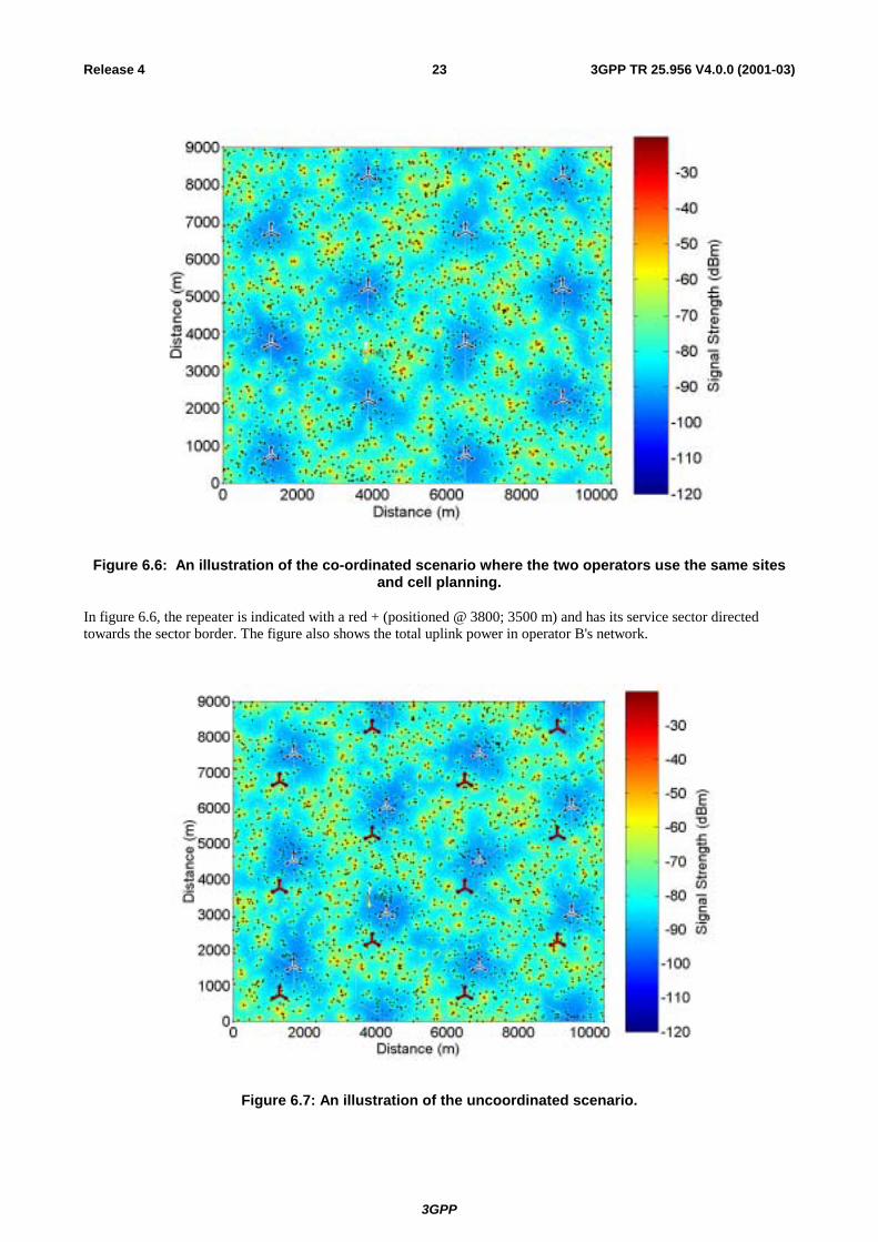
Figure 6.7: An illustration of the uncoordinated scenario.
3GPP
3GPP TR 25.956 V4.0.0 (2001-03)24Release 4
In figure 6.7, the repeater's position is indicated with a red + (positioned @ 3800; 3500 m). The figure also shows the total uplink power in operator B's network.
6.4.2 Simulation Assumptions The simulation assumptions used in this contribution are presented below in Table 6.7.
In is important to highlight that Operator A has an unloaded network and hence the additional interference caused by the UEs ACIR on Operator B's up-link is not included in the simulations.
Furthermore, the downlink is not considered and hence the possibility that UE's are dropped on the downlink due to ACIR from the repeater has not been considered..
Table 6.7: Simulation assumptions
Coupling loss, BS-Repeater 100 dB Minimum Coupling loss UE-Repeater 70 dB NLOS path loss model for the mobile [2] 128.1+37.6*log10(r) dB Log-Normal fading; standard deviation 6 dB Repeater adjacent channel gain 48 dB Repeater output power 33 dBm UE antenna gain 0 dBi UE power range -50 -- 24 dBm Cell radius 1 000 m Power Control Perfect Simulation type 36 cells; Monte-Carlo; Wrap-around Base station and repeater serving antenna 65° HBW; 15 dBi Sectors/BS 3
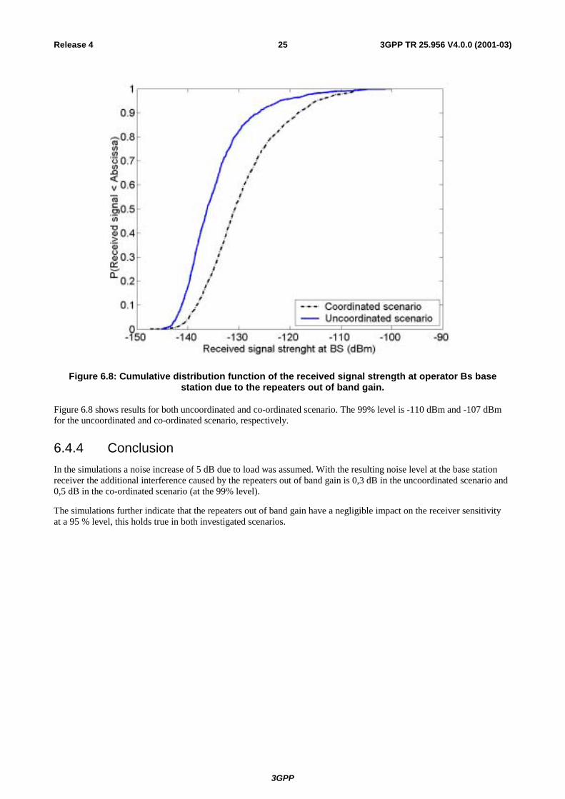
6.4.3 Results The results from the simulations are shown in Fig. 6.8 as cumulative distribution functions of the power received at Operator B's base station.
We find that there are some differences between the co-ordinated and uncoordinated scenarios. The simulations indicate the co-ordinated scenario gives a received power, which on average is about 5 dB greater than the uncoordinated.
From Fig. 6.8 we find that the received power is less than -110 dBm at the 99% level for the uncoordinated scenario. The corresponding value for the co-ordinated scenario is -107 dBm.
3GPP
3GPP TR 25.956 V4.0.0 (2001-03)25Release 4
Figure 6.8: Cumulative distribution function of the received signal strength at operator Bs base station due to the repeaters out of band gain.
Figure 6.8 shows results for both uncoordinated and co-ordinated scenario. The 99% level is -110 dBm and -107 dBm for the uncoordinated and co-ordinated scenario, respectively.
6.4.4 Conclusion In the simulations a noise increase of 5 dB due to load was assumed. With the resulting noise level at the base station receiver the additional interference caused by the repeaters out of band gain is 0,3 dB in the uncoordinated scenario and 0,5 dB in the co-ordinated scenario (at the 99% level).
The simulations further indicate that the repeaters out of band gain have a negligible impact on the receiver sensitivity at a 95 % level, this holds true in both investigated scenarios.
3GPP
3GPP TR 25.956 V4.0.0 (2001-03)26Release 4
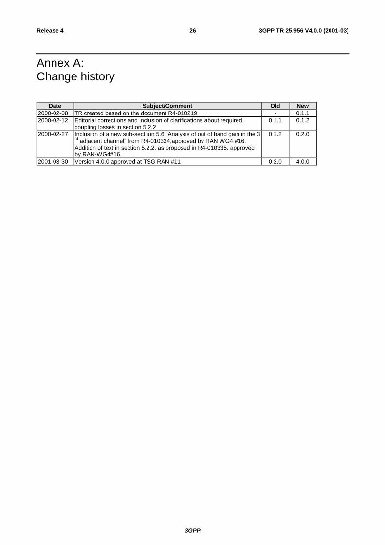
Annex A: Change history
Date Subject/Comment Old New 2000-02-08 TR created based on the document R4-010219 - 0.1.1 2000-02-12 Editorial corrections and inclusion of clarifications about required
coupling losses in section 5.2.2 0.1.1 0.1.2
2000-02-27 Inclusion of a new sub-sect ion 5.6 “Analysis of out of band gain in the 3 rd adjacent channel” from R4-010334,approved by RAN WG4 #16. Addition of text in section 5.2.2, as proposed in R4-010335, approved by RAN-WG4#16.
0.1.2 0.2.0
2001-03-30 Version 4.0.0 approved at TSG RAN #11 0.2.0 4.0.0