Embed Size (px)
Citation preview

ETSI TS 125 116 V10.0.0 (2011-05)
Technical Specification
Universal Mobile Telecommunications System (UMTS);UTRA repeater radio transmission and reception (LCR TDD)
(3GPP TS 25.116 version 10.0.0 Release 10)

ETSI
ETSI TS 125 116 V10.0.0 (2011-05)13GPP TS 25.116 version 10.0.0 Release 10
Reference DTS/TSGR-0425116va00
Keywords UMTS
ETSI
650 Route des Lucioles F-06921 Sophia Antipolis Cedex - FRANCE
Tel.: +33 4 92 94 42 00 Fax: +33 4 93 65 47 16
Siret N° 348 623 562 00017 - NAF 742 C
Association à but non lucratif enregistrée à la Sous-Préfecture de Grasse (06) N° 7803/88
Important notice
Individual copies of the present document can be downloaded from: http://www.etsi.org
The present document may be made available in more than one electronic version or in print. In any case of existing or perceived difference in contents between such versions, the reference version is the Portable Document Format (PDF).
In case of dispute, the reference shall be the printing on ETSI printers of the PDF version kept on a specific network drive within ETSI Secretariat.
Users of the present document should be aware that the document may be subject to revision or change of status. Information on the current status of this and other ETSI documents is available at
http://portal.etsi.org/tb/status/status.asp
If you find errors in the present document, please send your comment to one of the following services: http://portal.etsi.org/chaircor/ETSI_support.asp
Copyright Notification
No part may be reproduced except as authorized by written permission. The copyright and the foregoing restriction extend to reproduction in all media.
© European Telecommunications Standards Institute 2011.
All rights reserved.
DECTTM, PLUGTESTSTM, UMTSTM, TIPHONTM, the TIPHON logo and the ETSI logo are Trade Marks of ETSI registered for the benefit of its Members.
3GPPTM is a Trade Mark of ETSI registered for the benefit of its Members and of the 3GPP Organizational Partners. LTE™ is a Trade Mark of ETSI currently being registered
for the benefit of its Members and of the 3GPP Organizational Partners. GSM® and the GSM logo are Trade Marks registered and owned by the GSM Association.

ETSI
ETSI TS 125 116 V10.0.0 (2011-05)23GPP TS 25.116 version 10.0.0 Release 10
Intellectual Property Rights IPRs essential or potentially essential to the present document may have been declared to ETSI. The information pertaining to these essential IPRs, if any, is publicly available for ETSI members and non-members, and can be found in ETSI SR 000 314: "Intellectual Property Rights (IPRs); Essential, or potentially Essential, IPRs notified to ETSI in respect of ETSI standards", which is available from the ETSI Secretariat. Latest updates are available on the ETSI Web server (http://webapp.etsi.org/IPR/home.asp).
Pursuant to the ETSI IPR Policy, no investigation, including IPR searches, has been carried out by ETSI. No guarantee can be given as to the existence of other IPRs not referenced in ETSI SR 000 314 (or the updates on the ETSI Web server) which are, or may be, or may become, essential to the present document.
Foreword This Technical Specification (TS) has been produced by ETSI 3rd Generation Partnership Project (3GPP).
The present document may refer to technical specifications or reports using their 3GPP identities, UMTS identities or GSM identities. These should be interpreted as being references to the corresponding ETSI deliverables.
The cross reference between GSM, UMTS, 3GPP and ETSI identities can be found under http://webapp.etsi.org/key/queryform.asp.

ETSI
ETSI TS 125 116 V10.0.0 (2011-05)33GPP TS 25.116 version 10.0.0 Release 10
Contents
Intellectual Property Rights ................................................................................................................................ 2
Foreword ............................................................................................................................................................. 2
Foreword ............................................................................................................................................................. 5
1 Scope ........................................................................................................................................................ 6
2 References ................................................................................................................................................ 6
3 Definitions, symbols and abbreviations ................................................................................................... 6
3.1 Definitions .......................................................................................................................................................... 6
3.2 Symbols .............................................................................................................................................................. 7
3.3 Abbreviations ..................................................................................................................................................... 7
4 General ..................................................................................................................................................... 7
4.1 Relationship between Minimum Requirements and Test Requirements ............................................................ 8
4.2 Regional requirements ........................................................................................................................................ 9
5 Frequency bands and channel arrangement ............................................................................................ 10
5.1 General ............................................................................................................................................................. 10
5.2 Frequency bands ............................................................................................................................................... 10
5.3 TX-RX frequency separation ........................................................................................................................... 10
5.4 Channel arrangement ........................................................................................................................................ 11
5.4.1 Channel spacing .......................................................................................................................................... 11
5.4.2 Channel raster ............................................................................................................................................. 11
5.4.3 Channel number .......................................................................................................................................... 11
6 Output power .......................................................................................................................................... 11
6.1 Maximum output power ................................................................................................................................... 11
6.1.1 Minimum Requirements ............................................................................................................................. 11
7 Frequency stability ................................................................................................................................. 12
7.1 Minimum requirement ...................................................................................................................................... 12
8 Out of band gain ..................................................................................................................................... 12
8.1 Minimum requirement ...................................................................................................................................... 12
9 Unwanted emission ................................................................................................................................ 13
9.1 Spectrum emission mask .................................................................................................................................. 13
9.2 Spurious emissions ........................................................................................................................................... 14
9.2.1 Mandatory Requirements ............................................................................................................................ 15
9.2.1.1 Spurious emissions (Category A) .......................................................................................................... 15
9.2.1.1.1 Minimum Requirement ................................................................................................................... 15
9.2.1.2 Spurious emissions (Category B) .......................................................................................................... 15
9.2.1.2.1 Minimum Requirement ................................................................................................................... 15
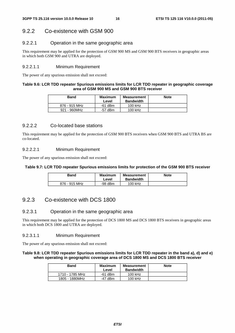
9.2.2 Co-existence with GSM 900 ....................................................................................................................... 16
9.2.2.1 Operation in the same geographic area ................................................................................................. 16
9.2.2.1.1 Minimum Requirement ................................................................................................................... 16
9.2.2.2 Co-located base stations ........................................................................................................................ 16
9.2.2.2.1 Minimum Requirement ................................................................................................................... 16
9.2.3 Co-existence with DCS 1800 ...................................................................................................................... 16
9.2.3.1 Operation in the same geographic area ................................................................................................. 16
9.2.3.1.1 Minimum Requirement ................................................................................................................... 16
9.2.3.2 Co-located base stations ........................................................................................................................ 17
9.2.3.2.1 Minimum Requirement ................................................................................................................... 17
9.2.4 Co-existence with UTRA-FDD .................................................................................................................. 17
9.2.4.1 Operation in the same geographic area ................................................................................................. 17
9.2.4.1.1 Minimum Requirement ................................................................................................................... 17
9.2.4.2 Co-located base stations ........................................................................................................................ 18
9.2.4.2.1 Minimum Requirement ................................................................................................................... 18

ETSI
ETSI TS 125 116 V10.0.0 (2011-05)43GPP TS 25.116 version 10.0.0 Release 10
9.2.5 Co-existence with unsynchronised TDD .................................................................................................... 18
9.2.5.1 Operation in the same geographic area ................................................................................................. 18
9.2.5.1.1 Minimum Requirement ................................................................................................................... 19
9.2.5.2 Co-located base stations ........................................................................................................................ 19
9.2.5.2.1 Minimum Requirement ................................................................................................................... 19
10 Modulation accuracy .............................................................................................................................. 20
10.1 Error Vector Magnitude ................................................................................................................................... 20
10.1.1 Minimum requirement ................................................................................................................................ 20
10.2 Peak code domain error .................................................................................................................................... 20
10.2.1 Minimum requirement ................................................................................................................................ 20
11 Input intermodulation ............................................................................................................................. 20
11.1 General requirement ......................................................................................................................................... 20
11.1.1 Minimum requirement ................................................................................................................................ 20
12 Output intermodulation .......................................................................................................................... 21
12.0 General ............................................................................................................................................................. 21
12.1 Minimum requirement ...................................................................................................................................... 21
13 Adjacent Channel Rejection Ratio (ACRR) ........................................................................................... 21
13.1 Definitions and applicability ............................................................................................................................ 21
13.2 Co-existence with UTRA ................................................................................................................................. 21
13.2.1. Minimum Requirements ................................................................................................................................... 21
14 Timing Accuracy .................................................................................................................................... 22
14.1 Minimum requirement ...................................................................................................................................... 22
Annex A (normative): Environmental requirements for the Repeater equipment ........................ 24
Annex B (informative): Change history ............................................................................................... 25
History .............................................................................................................................................................. 26

ETSI
ETSI TS 125 116 V10.0.0 (2011-05)53GPP TS 25.116 version 10.0.0 Release 10
Foreword This Technical Specification has been produced by the 3rd Generation Partnership Project (3GPP).
The contents of the present document are subject to continuing work within the TSG and may change following formal TSG approval. Should the TSG modify the contents of the present document, it will be re-released by the TSG with an identifying change of release date and an increase in version number as follows:
Version x.y.z
where:
x the first digit:
1 presented to TSG for information;
2 presented to TSG for approval;
3 or greater indicates TSG approved document under change control.
y the second digit is incremented for all changes of substance, i.e. technical enhancements, corrections, updates, etc.
z the third digit is incremented when editorial only changes have been incorporated in the document.

ETSI
ETSI TS 125 116 V10.0.0 (2011-05)63GPP TS 25.116 version 10.0.0 Release 10
1 Scope The present document establishes the minimum RF characteristics of LCR TDD Repeater.
2 References The following documents contain provisions which, through reference in this text, constitute provisions of the present document.
• References are either specific (identified by date of publication, edition number, version number, etc.) or non-specific.
• For a specific reference, subsequent revisions do not apply.
• For a non-specific reference, the latest version applies. In the case of a reference to a 3GPP document (including a GSM document), a non-specific reference implicitly refers to the latest version of that document in the same Release as the present document.
[1] 3GPP TR 21.905: "Vocabulary for 3GPP Specifications".
[2] ITU-R Recommendation SM.329, "Unwanted emissions in the spurious domain".
[3] ITU-R Recommendation M.1545: 'Measurement uncertainty as it applies to test limits for the terrestrial component of International Mobile Telecommunications-2000'.
[4] 3GPP TS 25.153: 'LCR TDD Repeater conformance testing'
[5] 3GPP TR 25.942: "RF system scenarios".
[6] IEC 60721-3-3 (2002): "Classification of environmental conditions - Part 3: Classification of groups of environmental parameters and their severities - Section 3: Stationary use at weather protected locations".
[7] IEC 60721-3-4 (1995): "Classification of environmental conditions - Part 3: Classification of groups of environmental parameters and their severities - Section 4: Stationary use at non-weather protected locations".
3 Definitions, symbols and abbreviations
3.1 Definitions For the purposes of the present document, the terms and definitions given in TR 21.905 [1] and the following apply. A term defined in the present document takes precedence over the definition of the same term, if any, in TR 21.905 [1].
Carrier: The modulated waveform conveying the LCR TDD physical channels
Channel bandwidth: The RF bandwidth supporting a single LCR TDD RF carrier with the transmission bandwidth configured in the uplink or downlink of a cell. The channel bandwidth is measured in MHz and is used as a reference for transmitter and receiver RF requirements.
Channel edge: The lowest and highest frequency of the LCR TDD carrier, separated by the channel bandwidth.
Donor coupling loss: is the coupling loss between the repeater and the donor base station.
Downlink: Signal path where base station transmits and mobile receives.

ETSI
ETSI TS 125 116 V10.0.0 (2011-05)73GPP TS 25.116 version 10.0.0 Release 10
Maximum output power, Pmax: This is the mean power level per carrier measured at the antenna connector of the Repeater in specified reference condition.
Output power, Pout: This is the mean power of one carrier at maximum repeater gain delivered to a load with resistance equal to the nominal load impedance of the transmitter.
Pass band: The repeater can have one or several pass bands. The pass band is the frequency range that the repeater operates in with operational configuration. This frequency range can correspond to one or several consecutive nominal channels. If they are not consecutive each subset of channels shall be considered as an individual pass band.
Rated output power: Rated output power of the repeater is the mean power level per carrier that the manufacturer has declared to be available at the antenna connector.
Repeater: A device that receives, amplifies and transmits the radiated or conducted RF carrier both in the down-link direction (from the base station to the mobile area) and in the up-link direction (from the mobile to the base station)
Transmission bandwidth: Bandwidth of an instantaneous transmission from a UE or BS, measured in Resource Block units.
Transmission bandwidth configuration: The highest transmission bandwidth allowed for uplink or downlink in a given channel bandwidth, measured in Resource Block units.
Uplink: Signal path where mobile transmits and base station receives.
3.2 Symbols For the purposes of the present document, the following symbols apply:
BWChannel Channel bandwidth BWConfig Transmission bandwidth configuration, expressed in MHz. BWMeas Measurement bandwidth BWSignal Bandwidth of the repeater input signal filling the repeater pass band FDL_low The lowest frequency of the downlink operating band FDL_high The highest frequency of the downlink operating band FUL_low The lowest frequency of the uplink operating band FUL_high The highest frequency of the uplink operating band f_offset_PB Distance from the channel edge frequency of the first or last channel in the pass band NDL Downlink LARFCN NOffs-DL Offset used for calculating downlink LARFCN NOffs-UL Offset used for calculating uplink LARFCN NRB Transmission bandwidth configuration, expressed in units of resource blocks NUL Uplink LARFCN Pmax Maximum output power Pout Output power
3.3 Abbreviations For the purposes of the present document, the abbreviations given in TR 21.905 [1] and the following apply. An abbreviation defined in the present document takes precedence over the definition of the same abbreviation, if any, in TR 21.905 [1].
ACRR Adjacent Channel Rejection Ratio BS Base Station LARFCN LCR TDD Absolute Radio Frequency Channel Number PB Pass Band
4 General This specification applies only to LCR TDD repeaters.
Unless otherwise stated, all requirements in this specification apply to both the up-link and down-link directions.

ETSI
ETSI TS 125 116 V10.0.0 (2011-05)83GPP TS 25.116 version 10.0.0 Release 10
4.1 Relationship between Minimum Requirements and Test Requirements
The Minimum Requirements given in this specification make no allowance for measurement uncertainty. The test specification TS 25.153 section 4 defines Test Tolerances. These Test Tolerances are individually calculated for each test. The Test Tolerances are used to relax the Minimum Requirements in this specification to create Test Requirements.
The measurement results returned by the Test System are compared - without any modification - against the Test Requirements as defined by the shared risk principle.
The Shared Risk principle is defined in ITU-R M.1545 [3].

ETSI
ETSI TS 125 116 V10.0.0 (2011-05)93GPP TS 25.116 version 10.0.0 Release 10
4.2 Regional requirements Some requirements in the present document may only apply in certain regions. Table 4.2-1 lists all requirements that may be applied differently in different regions.
Table 4.2-1: List of regional requirements
Clause number
Requirement Comments
5.2 Channel bandwidth Some channel bandwidths may be applied regionally.
5.3 Frequency bands Some bands may be applied regionally. 5.4 Channel arrangement The requirement is applied according to what
frequency bands in Clause 5.3 that are supported by the Repeater.
6.1 Maximum output power In certain regions, the minimum requirement for normal conditions may apply also for some conditions outside the range of conditions defined as normal.
9.1.1.1 Operating band unwanted emissions (Category A)
This requirement is mandatory for regions where Category A limits for spurious emissions, as defined in ITU-R Recommendation SM.329 [2] apply.
9.1.1.2 Operating band unwanted emissions (Category B)
This requirement is mandatory for regions where Category B limits for spurious emissions, as defined in ITU-R Recommendation SM.329 [2], apply.
9.1.3 Operating band unwanted emissions : Additional requirements
These requirements may be applied regionally for some operating bands.
9.2.1.1 Spurious emissions (Category A) This requirement is mandatory for regions where Category A limits for spurious emissions, as defined in ITU-R Recommendation SM.329 [2] apply.
9.2.1.2 Spurious emissions (Category B) This requirement is mandatory for regions where Category B limits for spurious emissions, as defined in ITU-R Recommendation SM.329 [2], apply.
9.2.2.1 Co-existence with GSM900 -Operation in the same geographic area
This requirement may be applied for the protection of GSM 900 MS and GSM 900 BTS in geographic areas in which both GSM 900 and LCR TDD repeater are deployed.
9.2.2.2 Co-existence with GSM900 - Co-located base stations
This requirement may be applied for the protection of GSM 900 BTS receivers when GSM 900 BTS and LCR TDD repeater are co-located.
9.2.3.1 Co-existence with DCS1800 -Operation in the same geographic area
This requirement may be applied for the protection of DCS 1800 MS and DCS 1800 BTS in geographic areas in which both DCS 1800 and LCR TDD repeater are deployed.
9.2.3.2 Co-existence with DCS1800 - Co-located base stations
This requirement may be applied for the protection of DCS 1800 BTS receivers when DCS 1800 BTS and LCR TDD repeater are co-located.
9.2.4.1 Co-existence with UTRA FDD - Operation in the same geographic area
This requirement may be applied to geographic areas in which both LCR TDD repeater and UTRA-FDD are deployed.
9.2.4.2 Co-existence with UTRA FDD - Co-located base stations
This requirement may be applied for the protection of UTRA-FDD BS receivers when LCR TDD repeater and UTRA FDD BS are co-located.
9.2.5.1 Co-existence with unsynchronized TDD - Operation in the same geographic area
This requirement may be applied for the protection of UTRA-TDD BS receivers in same geographic areas in which unsynchronized TDD is deployed.
9.2.5.2 Co-existence with unsynchronized TDD -Co-located base stations
This requirement may be applied for the protection of UTRA-TDD BS receivers when UTRA-TDD BS are unsynchronized co-located.
11.2 Input Intermodulation: Co-location with other systems
These requirements may be applied for the protection of FDD Repeater input when GSM900, DCS1800, PCS1900, GSM850, UTRA FDD, UTRA TDD and/or E-UTRA BS are co-located with an LCR TDD Repeater.

ETSI
ETSI TS 125 116 V10.0.0 (2011-05)103GPP TS 25.116 version 10.0.0 Release 10
11.3 Input Intermodulation: Co-existence with other systems
These requirements may be applied when GSM900, DCS1800, PCS1900, GSM850, UTRA FDD, UTRA TDD and/or E-UTRA BS operating in another frequency band co-exist with an LCR TDD Repeater.
5 Frequency bands and channel arrangement
5.1 General The information presented in this section is based on the chip rates of 1.28 Mcps TDD.
NOTE: Other chip rates may be considered in future releases.
5.2 Frequency bands UTRA/TDD is designed to operate in the following bands;
a) 1900 - 1920 MHz: Uplink and downlink transmission
2010 - 2025 MHz Uplink and downlink transmission
b) 1850 - 1910 MHz Uplink and downlink transmission
1930 - 1990 MHz Uplink and downlink transmission
c) 1910 - 1930 MHz Uplink and downlink transmission
d) 2570 - 2620 MHz Uplink and downlink transmission
e) 2300 - 2400 MHz Uplink and downlink transmission
f) 1880 - 1920 MHz: Uplink and downlink transmission
Note: Deployment in existing and other frequency bands is not precluded.
The co-existence of TDD and FDD in the same bands is still under study in WG4.
5.3 TX-RX frequency separation
No TX-RX frequency separation is required as Time Division Duplex (TDD) is employed. Each subframe consists of 7 main timeslots where all main timeslots (at least the first one) before the single switching point are allocated DL and all main timeslots (at least the last one) after the single switching point are allocated UL.

ETSI
ETSI TS 125 116 V10.0.0 (2011-05)113GPP TS 25.116 version 10.0.0 Release 10
5.4 Channel arrangement
5.4.1 Channel spacing
The channel spacing is 1.6MHz, but this can be adjusted to optimise performance in a particular deployment scenario.
5.4.2 Channel raster
The channel raster is 200 kHz for all bands, which means that the carrier frequency must be a multiple of 200 kHz.
5.4.3 Channel number
The carrier frequency is designated by the UTRA absolute radio frequency channel number (UARFCN). The value of the UARFCN in the IMT2000 band is defined in the general case as follows:
Nt = 5 ∗ F 0.0 ≤ F ≤ 3276.6 MHz
where F is the carrier frequency in MHz.
6 Output power Output power, Pout, of the repeater is the mean power of one carrier at maximum repeater gain delivered to a load with resistance equal to the nominal load impedance of the transmitter.
Rated output power, PRAT, of the repeater is the mean power level per carrier at maximum repeater gain that the manufacturer has declared to be available at the antenna connector.
6.1 Maximum output power Maximum output power, Pmax, of the repeater is the mean power level per carrier measured at the antenna connector in specified reference condition.
6.1.1 Minimum Requirements
The requirements shall apply at maximum gain, with LCR TDD signals in the pass band of the repeater, at levels that produce the maximum rated output power per channel.
When the power of all signals is increased by 10 dB, compared to the power level that produce the maximum rated output power, the requirements shall still be met.
In normal conditions, the Repeater maximum output power shall remain within limits specified in Table 6.1 relative to the manufacturer's rated output power.
Table 6.1: Repeater output power; normal conditions
Rated output power Limit P ≥ 31 dBm +2 dB and -2 dB P < 31 dBm +3 dB and -3 dB
In extreme conditions, the Repeater maximum output power shall remain within the limits specified in Table 6.2 relative to the manufacturer's rated output power.

ETSI
ETSI TS 125 116 V10.0.0 (2011-05)123GPP TS 25.116 version 10.0.0 Release 10
Table 6.2: Repeater output power; extreme conditions
Rated output power Limit P ≥ 31 dBm +2,5 dB and -2,5 dB P < 31 dBm +4 dB and -4 dB
In certain regions, the minimum requirement for normal conditions may apply also for some conditions outside the ranges of conditions defined as normal.
7 Frequency stability Frequency stability is the ability to maintain the same frequency on the output signal with respect to the input signal.
7.1 Minimum requirement
The frequency deviation of the output signal with respect to the input signal shall be no more than ±0,01 ppm.
8 Out of band gain Out of band gain refers to the gain of the repeater outside the pass band.
8.1 Minimum requirement The intended use of a repeater in a system is to amplify the in band signals and not to amplify the out of band emission of the donor base station. In the intended application of the repeater, the out of band gain is less than the donor coupling loss. The repeater minimum donor coupling loss shall be declared by the manufacturer. This is this the minimum required attenuation between the donor BS and the repeater for proper repeater operation.
The gain outside the pass band shall not exceed the maximum level specified in table 8.1, where:
- f_offset is the distance from the centre frequency of the first or last channel within the pass band.
Table 8.1: Out of band gain limits 1
Frequency offset from the carrier frequency, f_offset
Maximum gain
1,0 ≤ f_offset < 1,8 MHz 60 dB 1,8 ≤ f_offset < 5,8 MHz 45 dB
5,8 ≤ f_offset < 10,8 MHz 45 dB 10,8 MHz ≤ f_offset 35 dB
For 10,8 MHz ≤ f_offset the out of band gain shall not exceed the maximum gain of table 8.2 or the maximum gain stated in table 8.1 whichever is lower.
Table 8.2: Out of band gain limits 2
Repeater maximum output power as in 9.1.1.1
Maximum gain
P < 31 dBm Out of band gain ≤ minimum donor coupling loss 31 dBm ≤ P < 43 dBm Out of band gain ≤ minimum donor coupling loss
P ≥ 43 dBm Out of band gain ≤ minimum donor coupling loss - (P-43dBm) NOTE 1: The out of band gain is considered with 10,8 MHz ≤ f_offset

ETSI
ETSI TS 125 116 V10.0.0 (2011-05)133GPP TS 25.116 version 10.0.0 Release 10
9 Unwanted emission
9.1 Spectrum emission mask The mask defined in Table 9.1 to 9.3 may be mandatory in certain regions. In other regions this mask may not be applied.
For regions where this clause applies, the requirement shall be met by a LCR TDD repeater transmitting on a single RF carrier configured in accordance with the manufacturer"s specification. Emissions shall not exceed the maximum level specified in table 9.1 to 9.3 for the appropriate LCR TDD repeater maximum output power, in the frequency range from Δf = 0.8 MHz to Δf max from the carrier frequency, where:
- Δf is the separation between the carrier frequency and the nominal -3dB point of the measuring filter closest to the carrier frequency.
- f_offset is the separation between the carrier frequency and the center frequency of the measuring filter.
- f_offsetmax is either 4 MHz or the offset to the UMTS Tx band edge as defined in section 5.2, whichever is the greater.
- Δf max is equal to f_offsetmax minus half of the bandwidth of the measurement filter.
0.8 1.0 1.8
-20 -5
Frequency separation Δf from the carrier [MHz]
Pow
er d
ensi
ty in
30k
Hz
[dB
m]
Δf max
-25
-30
-35
-40
-45
Pow
er d
ensi
ty in
1 M
Hz
[dB
m]
-10
-15
-20
-25
-30
2.4
P = 34 dBmP = 34 dBm
P = 26 dBmP = 26 dBm
Illustrative diagram of spectrum emission mask
Figure 9.1

ETSI
ETSI TS 125 116 V10.0.0 (2011-05)143GPP TS 25.116 version 10.0.0 Release 10
Table 9.1: Spectrum emission mask values, BS maximum output power P ≥ 34 dBm
Frequency offset of measurement filter -
3dB point, Δf
Frequency offset of measurement filter centre
frequency, f_offset
Maximum level Measurement bandwidth
0.8 MHz ≤ Δf < 1.0 MHz
0.815MHz ≤ f_offset < 1.015MHz
-20 dBm 30 kHz
1.0 MHz ≤ Δf < 1.8 MHz
1.015MHz ≤ f_offset < 1.815MHz dB
MHz
offsetfdBm ⎟
⎠
⎞⎜⎝
⎛ −⋅−− 015,1_
1020 30 kHz
See note 1.815MHz ≤ f_offset < 2.3MHz
-28 dBm 30 kHz
1.8 MHz ≤ Δf ≤Δfmax 2.3MHz ≤ f_offset < f_offsetmax
-13 dBm 1 MHz
Table 9.2: Spectrum emission mask values, BS maximum output power 26 ≤ P < 34 dBm
Frequency offset of measurement filter
-3dB point, Δf
Frequency offset of measurement filter centre
frequency, f_offset
Maximum level Measurement bandwidth
0.8 MHz ≤ Δf < 1.0 MHz
0.815MHz ≤ f_offset < 1.015MHz
P-54 dB 30 kHz
1.0 MHz ≤ Δf < 1.8 MHz
1.015MHz ≤ f_offset < 1.815MHz dB
MHz
offsetfdBP ⎟
⎠
⎞⎜⎝
⎛ −⋅−− 015,1_
1054 30 kHz
See note 1.815 MHz ≤ f_offset < 2.3 MHz
P-62 dB 30 kHz
1.8 MHz ≤ Δf ≤Δfmax 2.3 MHz ≤ f_offset < f_offsetmax
P - 47 dB 1 MHz
Table 9.3: Spectrum emission mask values, BS maximum output power P < 26 dBm
Frequency offset of measurement filter -
3dB point, Δf
Frequency offset of measurement filter centre
frequency, f_offset
Maximum level Measurement bandwidth
0.8 MHz≤ Δf < 1.0 MHz
0.815MHz ≤ f_offset < 1.015MHz
-28 dBm 30 kHz
1.0 MHz≤ Δf < 1.8 MHz
1.015MHz ≤ f_offset < 1.815MHz dB
MHz
offsetfdBm ⎟
⎠
⎞⎜⎝
⎛ −⋅−− 015,1_
1028 30 kHz
See note 1.815MHz ≤ f_offset < 2.3MHz
-36 dBm 30 kHz
1.8 MHz≤ Δf ≤Δfmax 2.3MHz ≤ f_offset < f_offsetmax
-21 dBm 1 MHz
NOTE: This frequency range ensures that the range of values of f_offset is continuous.
9.2 Spurious emissions Spurious emissions are emissions which are caused by unwanted transmitter effects such as harmonics emission, parasitic emission, intermodulation products and frequency conversion products, but exclude out of band emissions. This is measured at the base station RF output port.
The requirements shall apply whatever the type of transmitter considered (single carrier or multi carrier). It applies for all transmission modes foreseen by the manufacturer"s.
For 1.28 Mcps TDD option, either requirement applies at frequencies within the specified frequency ranges which are more than 4 MHz under the first carrier frequency used or more than 4 MHz above the last carrier frequency used.
Unless otherwise stated, all requirements are measured as mean power.

ETSI
ETSI TS 125 116 V10.0.0 (2011-05)153GPP TS 25.116 version 10.0.0 Release 10
9.2.1 Mandatory Requirements
The requirements of either subclause 9.2.1.1 or subclause 9.2.1.2 shall apply.
9.2.1.1 Spurious emissions (Category A)
The following requirements shall be met in cases where Category A limits for spurious emissions, as defined in ITU-R Recommendation SM.329-9 [1], are applied.
9.2.1.1.1 Minimum Requirement
The power of any spurious emission shall not exceed:
Table 9.4: LCR TDD repeater Mandatory spurious emissions limits, Category A
Band Minimum requirement
Measurement Bandwidth
Notes
9kHz - 150kHz
-13 dBm
1 kHz Note 1 150kHz - 30MHz 10 kHz Note 1 30MHz - 1GHz 100 kHz Note 1
1GHz - 12.75 GHz 1 MHz Note 2 NOTE 1: Bandwidth as in ITU SM.329 [1], s4.1 NOTE 2: Upper frequency as in ITU SM.329 [1], s2.5 table 1
NOTE: only the measurement bands are different according to the occupied bandwidth.
9.2.1.2 Spurious emissions (Category B)
The following requirements shall be met in cases where Category B limits for spurious emissions, as defined in ITU-R Recommendation SM.329 [1], are applied.
9.2.1.2.1 Minimum Requirement
The power of any spurious emission shall not exceed:
Table 9.5: LCR TDD repeater Mandatory spurious emissions limits, Category B
Band Maximum Level
Measurement Bandwidth
Notes
9kHz - 150kHz -36 dBm 1 kHz Note 1 150kHz - 30MHz - 36 dBm 10 kHz Note 1 30MHz - 1GHz -36 dBm 100 kHz Note 1
1GHz ↔
Fl -10 MHz
-30 dBm 1 MHz Note 1
Fl -10MHz
↔ Fu +10 MHz
-15 dBm 1 MHz Note 2
Fu +10 MHz ↔
12,5 GHz
-30 dBm 1 MHz Note 3
NOTE 1: Bandwidth as in ITU SM.329 [1], s4.1 NOTE 2: Limit based on ITU-R SM.329 [1], s4.3 and Annex 7 NOTE 3: Bandwidth as in ITU-R SM.329 [1], s4.3 and Annex 7. Upper frequency as in
ITU-R SM.329 [1], s2.5 table 1
Fl: Lower frequency of the band in which TDD operates Fu: Upper frequency of the band in which TDD operates
ETSI
ETSI TS 125 116 V10.0.0 (2011-05)163GPP TS 25.116 version 10.0.0 Release 10
9.2.2 Co-existence with GSM 900
9.2.2.1 Operation in the same geographic area
This requirement may be applied for the protection of GSM 900 MS and GSM 900 BTS receivers in geographic areas in which both GSM 900 and UTRA are deployed.
9.2.2.1.1 Minimum Requirement
The power of any spurious emission shall not exceed:
Table 9.6: LCR TDD repeater Spurious emissions limits for LCR TDD repeater in geographic coverage area of GSM 900 MS and GSM 900 BTS receiver
Band Maximum Level
Measurement Bandwidth
Note
876 - 915 MHz -61 dBm 100 kHz 921 - 960MHz -57 dBm 100 kHz
9.2.2.2 Co-located base stations
This requirement may be applied for the protection of GSM 900 BTS receivers when GSM 900 BTS and UTRA BS are co-located.
9.2.2.2.1 Minimum Requirement
The power of any spurious emission shall not exceed:
Table 9.7: LCR TDD repeater Spurious emissions limits for protection of the GSM 900 BTS receiver
Band Maximum Level
Measurement Bandwidth
Note
876 - 915 MHz -98 dBm 100 kHz
9.2.3 Co-existence with DCS 1800
9.2.3.1 Operation in the same geographic area
This requirement may be applied for the protection of DCS 1800 MS and DCS 1800 BTS receivers in geographic areas in which both DCS 1800 and UTRA are deployed.
9.2.3.1.1 Minimum Requirement
The power of any spurious emission shall not exceed:
Table 9.8: LCR TDD repeater Spurious emissions limits for LCR TDD repeater in the band a), d) and e) when operating in geographic coverage area of DCS 1800 MS and DCS 1800 BTS receiver
Band Maximum Level
Measurement Bandwidth
Note
1710 - 1785 MHz -61 dBm 100 kHz 1805 - 1880MHz -47 dBm 100 kHz

ETSI
ETSI TS 125 116 V10.0.0 (2011-05)173GPP TS 25.116 version 10.0.0 Release 10
Table 9.8a: LCR TDD repeater Spurious emissions limits for LCR TDD repeater in the band f) when operating in geographic coverage area of DCS 1800 MS and DCS 1800 BTS receiver operating in
1710-1755 MHz/1805-1850 MHz
Band Maximum Level
Measurement Bandwidth
Note
1710 - 1755 MHz -61 dBm 100 kHz 1805 - 1850MHz -47 dBm 100 kHz
9.2.3.2 Co-located base stations
This requirement may be applied for the protection of DCS 1800 BTS receivers when DCS 1800 BTS and UTRA BS are co-located.
9.2.3.2.1 Minimum Requirement
The power of any spurious emission shall not exceed:
Table 9.9: LCR TDD repeater Spurious emissions limits for LCR TDD repeater in the band a), d) and e) when co-located with DCS 1800 BTS
Band Maximum Level
Measurement Bandwidth
Note
1710 - 1785 MHz -98 dBm 100 kHz
Table 9.10: LCR TDD repeater Spurious emissions limits for LCR TDD repeater in the band f) when co-located with DCS1800 BTS
Band Maximum Level
Measurement Bandwidth
Note
1710 - 1755 MHz -98 dBm 100 kHz
9.2.4 Co-existence with UTRA-FDD
9.2.4.1 Operation in the same geographic area
This requirement may be applied to geographic areas in which both UTRA-TDD and UTRA-FDD operating in bands specified in Table 9.11 are deployed.
9.2.4.1.1 Minimum Requirement
For LCR TDD repeater which use carrier frequencies within the band 2010 - 2025 MHz the requirements applies at all frequencies within the specified frequency bands in table 9.11. For LCR TDD repeater which use carrier frequencies within the band 1900-1920 MHz, the requirement applies at frequencies within the specified frequency range which are more than 4 MHz above the last carrier used in the frequency band 1900-1920 MHz.
The power of any spurious emission shall not exceed:

ETSI
ETSI TS 125 116 V10.0.0 (2011-05)183GPP TS 25.116 version 10.0.0 Release 10
Table 9.11: LCR TDD repeater Spurious emissions limits for LCR TDD repeater in geographic coverage area of UTRA-FDD
Band Maximum Level Measurement Bandwidth Note 1920 - 1980 MHz -43 dBm (*) 3,84 MHz 2110 - 2170 MHz -52 dBm 1 MHz 2500 - 2570 MHz -43 dBm(**) 3.84 MHz 2620 - 2690 MHz -52 dBm 1 MHz
NOTE* For LCR TDD repeater which use carrier frequencies within the band 1900 - 1920 MHz or 1880-1920MHz, the requirement shall be measured RRC filtered mean power with the lowest centre frequency of measurement at 1922.6 MHz or 6.6 MHz above the highest TDD carrier used, whichever is higher.
NOTE ** For LCR TDD repeater which use carrier frequencies within the band 2570 - 2620 MHz, the requirement shall be measured RRC filtered mean power with the highest centre frequency of measurement at 2567.5 MHz or 6.6 MHz below the lowest TDD carrier used, whichever is lower.
NOTE: The requirements in Table 9.11 are based on a coupling loss of 70 dB between LCR TDD repeater and FDD Wide Area base stations.
9.2.4.2 Co-located base stations
This requirement may be applied for the protection of UTRA-FDD BS receivers when UTRA-TDD BS and UTRA FDD BS are co-located.
9.2.4.2.1 Minimum Requirement
For LCR TDD repeater which use carrier frequencies within the band 2010 - 2025 MHz the requirements applies at all frequencies within the specified frequency bands in table 9.12. For LCR TDD repeater which use carrier frequencies within the band 1900-1920 MHz, the requirement applies at frequencies within the specified frequency range which are more than 4 MHz above the last carrier used in the frequency band 1900-1920 MHz.
The power of any spurious emission shall not exceed:
Table 9.12: LCR TDD repeater Spurious emissions limits for BS co-located with UTRA-FDD
Band Maximum Level Measurement Bandwidth
1920 - 1980 MHz -80 dBm (*) 3,84 MHz 2110 - 2170 MHz -52 dBm 1 MHz 2500 - 2570 MHz - 80 dBm(**) 3.84 MHz 2620 - 2690 MHz -52 dBm 1 MHz
NOTE * For LCR TDD repeater which use carrier frequencies within the band 1900 - 1920 MHz or 1880-1920MHz, the requirement shall be measured RRC filtered mean power with the lowest centre frequency of measurement at 1922.6 MHz or 6.6 MHz above the highest TDD carrier used, whichever is higher.
NOTE ** For LCR TDD repeater which use carrier frequencies within the band 2570 - 2620 MHz, the requirement shall be measured RRC filtered mean power with the highest centre frequency of measurement at 2567.5 MHz or 6.6MHz below the lowest TDD carrier used, whichever is lower.
NOTE: The requirements in Table 9.12 are based on a minimum coupling loss of 30 dB between LCR TDD repeater and UTRA-FDD base stations.
9.2.5 Co-existence with unsynchronised TDD
9.2.5.1 Operation in the same geographic area
This requirement shall apply in case the equipment is operated in the same geographic area with unsynchronised TDD BS.

ETSI
ETSI TS 125 116 V10.0.0 (2011-05)193GPP TS 25.116 version 10.0.0 Release 10
9.2.5.1.1 Minimum Requirement
In geographic areas where only 1,28 Mcps TDD is deployed, the RRC filtered mean power of any spurious emission shall not exceed the limits specified in table 9.13, otherwise the limits in table 9.14 shall apply.
Table 9.13: LCR TDD repeater Spurious emissions limits for operation in same geographic area with unsynchronised 1,28 Mcps TDD
Band Maximum Level Measurement Bandwidth 1900 - 1920 MHz -39 dBm 1,28 MHz 2010 - 2025 MHz -39 dBm 1,28 MHz 2300 - 2400 MHz -39 dBm 1,28 MHz 2570 - 2620 MHz -39 dBm 1,28 MHz 1880 – 1920 MHz -39 dBm 1,28 MHz
Table 9.14: LCR TDD repeater Spurious emissions limits for operation in same geographic area with unsynchronised TDD
Band Maximum Level Measurement Bandwidth 1900 - 1920 MHz -39 dBm 3,84 MHz 2010 - 2025 MHz -39 dBm 3,84 MHz 2570 - 2620 MHz -39 dBm 3,84 MHz
NOTE: The requirements in Table 9.13 and 9.14 for the LCR TDD repeater are based on a minimum coupling loss of 67 dB between LCR TDD repeater and unsynchronised TDD base stations.
9.2.5.2 Co-located base stations
This requirement shall apply in case of co-location with unsynchronised TDD BS.
9.2.5.2.1 Minimum Requirement
In geographic areas where only 1,28 Mcps TDD is deployed, the RRC filtered mean power of any spurious emission in case of co-location shall not exceed the limits specified in table 9.15, otherwise the limits in table 9.16 shall apply.
Table 9.15: LCR TDD repeater Spurious emissions limits for co-location with unsynchronised 1,28 Mcps TDD
Band Maximum Level Measurement Bandwidth 1900 - 1920 MHz -76 dBm 1,28 MHz 2010 - 2025 MHz -76 dBm 1,28 MHz 2300 - 2400 MHz -76 dBm 1,28 MHz 2570 - 2620 MHz -76 dBm 1,28 MHz 1880 - 1920 MHz -76 dBm 1,28 MHz
NOTE: The requirement applies for frequencies more than 10 MHz below or above the supported frequency range declared by the vendor.
Table 9.16: LCR TDD repeater Spurious emissions limits for co-location with unsynchronised TDD
Band Maximum Level Measurement Bandwidth 1900 - 1920 MHz -76 dBm 3,84 MHz 2010 - 2025 MHz -76 dBm 3,84 MHz 2570 - 2620MHz -76 dBm 3,84 MHz
NOTE: The requirements in Table 9.15 and 9.16 for the LCR TDD repeater are based on a minimum coupling loss of 30 dB between unsynchronised TDD base stations.

ETSI
ETSI TS 125 116 V10.0.0 (2011-05)203GPP TS 25.116 version 10.0.0 Release 10
10 Modulation accuracy
10.1 Error Vector Magnitude The modulation accuracy is defined by the Error Vector Magnitude (EVM), which is a measure of the difference between the theoretical waveform and a modified version of the measured waveform. This difference is called the error vector. The measured waveform is modified by first passing it through a matched root raised cosine filter with bandwidth 1.28MHz and roll-off α=0.22. The waveform is then further modified by selecting the frequency, absolute phase, absolute amplitude and chip clock timing so as to minimise the error vector. The EVM result is defined as root of the ratio of the mean error vector power to the mean reference signal power expressed as a %.
The measurement interval is one power control group (timeslot). The repeater shall operate with an ideal LCR TDD signal in the pass band of the repeater at a level, which produce the maximum rated output power per channel, as specified by the manufacturer.
10.1.1 Minimum requirement
The Error Vector Magnitude shall not be worse than 8 %.
10.2 Peak code domain error The code domain error is computed by projecting the error vector power onto the code domain at a specific spreading factor. The error power for each code is defined as the ratio to the mean power of the reference waveform expressed in dB. And the Peak Code Domain Error is defined as the maximum value for Code Domain Error. The measurement interval is one timeslot.
10.2.1 Minimum requirement
The peak code domain error shall not exceed -30 dB at spreading factor 16.
11 Input intermodulation The input intermodulation is a measure of the capability of the repeater to inhibit the generation of interference in the pass band, in the presence of interfering signals on frequencies other than the pass band.
11.1 General requirement The following requirement applies for interfering signals in the frequency bands defined in sub-clause 5.2, depending on the repeaters pass band.
This requirement applies to the uplink and downlink of the repeater, at maximum gain.
11.1.1 Minimum requirement
For the parameters specified in table 11.1.1-1, the power in the pass band shall not increase with more than 10 dB at the output of the repeater as measured in the centre of the pass band, compared to the level obtained without interfering signals applied.
The frequency separation between the two interfering signals shall be adjusted so that the 3rd order intermodulation product is positioned in the centre of the pass band.
Table 11.1.1-1 specifies the parameters for two interfering signals, where:
- f1 offset is the offset from the channel edge frequency of the first or last channel in the pass band of the closer carrier.

ETSI
ETSI TS 125 116 V10.0.0 (2011-05)213GPP TS 25.116 version 10.0.0 Release 10
Table 11.1.1-1: Input intermodulation requirement
f1 offset Interfering Signal Levels
Type of signals Measurement bandwidth
1,0 MHz -40 dBm 2 CW carriers 1 MHz
12 Output intermodulation
12.0 General The transmit intermodulation performance is a measure of the capability of the transmitter to inhibit the generation of signals in its non linear elements caused by presence of the wanted signal and an interfering signal reaching the transmitter via the antenna.
The transmit intermodulation level is the power of the intermodulation products when a LCR TDD modulated interference signal is injected into the antenna connector at a mean power level of 30 dB lower than that of the mean power of the subject signal.
12.1 Minimum requirement
The frequency of the interference signal shall be ±1.6 MHz, ±3.2 MHz and ±4.8 MHz offset from the subject signal. The Transmit intermodulation level shall not exceed the out of band or the spurious emission requirements of section 9.1 and 9.2.
13 Adjacent Channel Rejection Ratio (ACRR)
13.1 Definitions and applicability Adjacent Channel Rejection Ratio (ACRR) is the ratio of the RRC weighted gain per carrier of the repeater in the pass band to the RRC weighted gain of the repeater on an adjacent channel. The carrier in the pass band and in the adjacent channel shall be of the same type (reference carrier).
The requirement shall apply to the uplink and downlink of Repeater, at maximum gain, where the donor link is maintained via antennas (over the air Repeater).
13.2 Co-existence with UTRA This requirement shall be applied for the protection of UTRA signals in geographic areas in which LCR TDD Repeater and UTRA BS are deployed so that they serve adjacent channels. The reference carrier is a UTRA-FDD carrier.
13.2.1. Minimum Requirements In normal conditions the ACRR shall be higher than the value specified in the Table 13.2.1-1.

ETSI
ETSI TS 125 116 V10.0.0 (2011-05)223GPP TS 25.116 version 10.0.0 Release 10
Table 13.2.1-1: Repeater ACRR
Co-existence with other systems
Repeater maximum output Pmax
Channel offset from the channel edge from the first or last 5MHz channel
within the pass band.
ACRR limit
UTRA
P ≥ 31 dBm 2,5 MHz 33dB P ≥ 31 dBm 5,0 MHz 33dB P < 31 dBm 2,5 MHz 20dB P < 31 dBm 5,0 MHz 20dB
Note: For co-existence with TDD, a narrow band requirement is for further study.
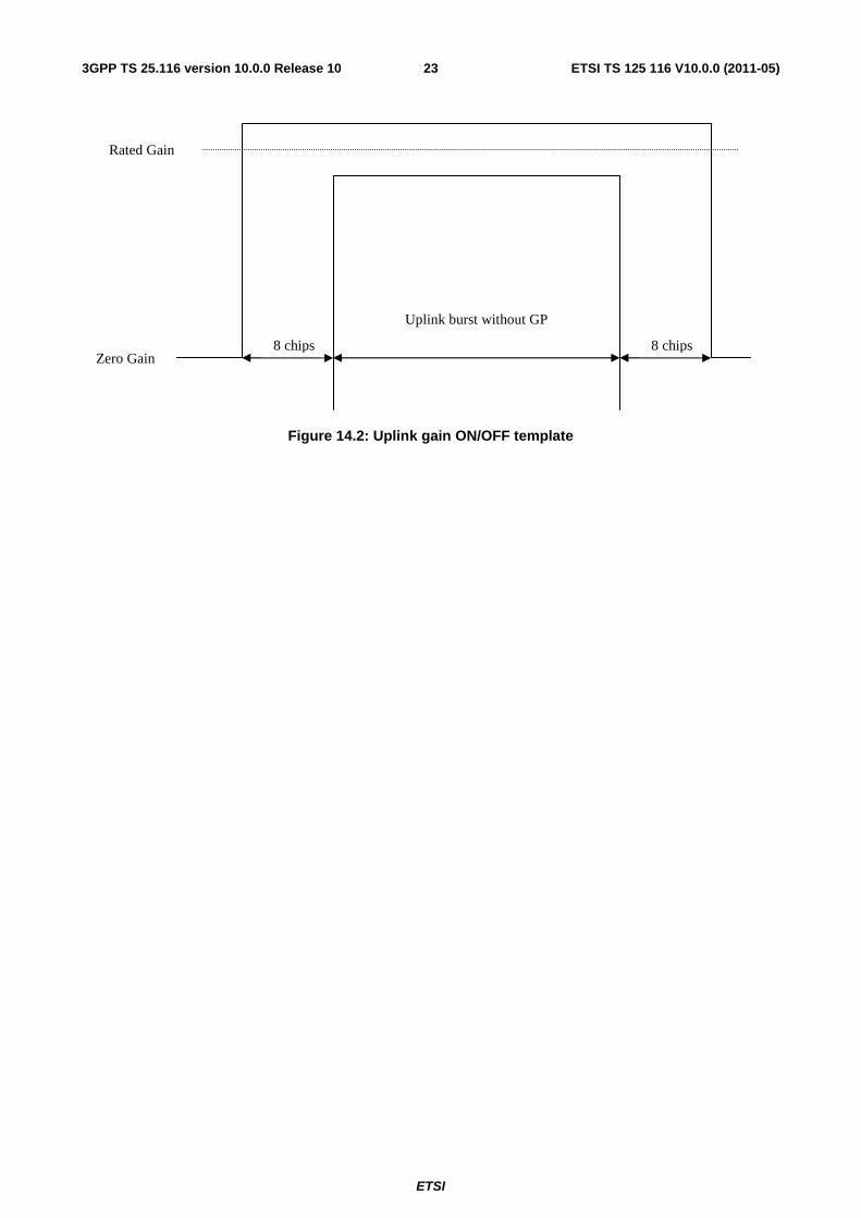
14 Timing Accuracy Timing Accuracy is the repeater synchronization accuracy with NodeB, it includes the downlink ramp on/off time and uplink ramp on/off time.
14.1 Minimum requirement The downlink gain versus time should meet the mask specified in figure 14.1. The beginning and end point of downlink burst is calculated according to the trigger given by NodeB or LCR TDD signal generator.
Figure 14.1: Downlink gain ON/OFF template
The uplink gain versus time should meet the mask specified in figure 14.2. The beginning and end point of uplink burst is calculated according to the trigger given by NodeB or LCR TDD signal generator.
8 chips 8 chips
Rated Gain
Zero Gain
Downlink burst without GP
ETSI
ETSI TS 125 116 V10.0.0 (2011-05)233GPP TS 25.116 version 10.0.0 Release 10
Figure 14.2: Uplink gain ON/OFF template
8 chips 8 chips
Rated Gain
Zero Gain
Uplink burst without GP

ETSI
ETSI TS 125 116 V10.0.0 (2011-05)243GPP TS 25.116 version 10.0.0 Release 10
Annex A (normative): Environmental requirements for the Repeater equipment The Repeater equipment shall fulfil all the requirements in the full range of environmental conditions for the relevant environmental class from the relevant IEC specifications listed below
60 721-3-3 "Stationary use at weather protected locations" [6];
60 721-3-4 "Stationary use at non weather protected locations" [7]
Normally it should be sufficient for all tests to be conducted using normal test conditions except where otherwise stated. For guidance on the use of test conditions to be used in order to show compliance refer to TS 25.153.

ETSI
ETSI TS 125 116 V10.0.0 (2011-05)253GPP TS 25.116 version 10.0.0 Release 10
Annex B (informative): Change history
Change history Date TSG # TSG Doc. CR Rev Subject/Comment Old New 2009-08 RAN4#52 R4-093324 TS skeleton created from 3GPP TS template. 0.0.1 2009-11 RAN4#53 R4-094876 TS with the TP approved at RAN4#52 and RAN4#52bis
R4-092917 Text proposal for LCR TDD Repeater Specification: Output Power
R4-092918 Text proposal for LCR TDD Repeater Specification: Frequency Error
R4-092919 Text proposal for LCR TDD Repeater Specification: EVM
R4-092920 Text proposal for LCR TDD Repeater Specification: PCDE
R4-092922 Text proposal for LCR TDD Repeater Specification: Output Intermodulation
R4-093323 Text Proposal for LCR TDD Repeater Specification: Frequency bands and channel arrangements
R4-093350 Text proposal for LCR TDD Repeater Specification: Input Intermodulation
R4-093351 Text proposal for LCR TDD Repeater Specification: Out of Band Gain
R4-093353 Text proposal for LCR TDD Repeater Specification: ACRR
R4-093363 Text proposal for LCR TDD Repeater Specification: Timing Accuracy
R4-093372 Text proposal for LCR TDD Repeater Specification: Unwanted Emissions
R4-093746 Text proposal for 25.116: Clause 1 to Clause 3 R4-094015 Text proposal for 25.116: Clause 4 General
0.0.1 1.0.0
2009-11 RAN#46 RP-091136 Presentation to TSG for information 2010-03 RAN#47 RP-100112 Version update, presentation to TSG for approval, 1.0.0 2.0.0 2010-03 RAN#47 RP-100112 Approved by TSG RAN 2.0.0 10.0.0

ETSI
ETSI TS 125 116 V10.0.0 (2011-05)263GPP TS 25.116 version 10.0.0 Release 10
History
Document history
V10.0.0 May 2011 Publication