Embed Size (px)
Citation preview

The Pennsylvania State University LionTech Rocket Labs 1
The Pennsylvania State University
46 Hammond Building State College, PA 16802
January 13, 2017
USLI Critical Design Review Report 2016-2017
Project Odyssey

The Pennsylvania State University LionTech Rocket Labs 2
Table of Contents .................................................................................................................. 2
List of Acronyms .................................................................................................................... 5
List of Variables ..................................................................................................................... 6
List of Figures ........................................................................................................................ 7
List of Tables ......................................................................................................................... 9
Section 1: General Information ............................................................................................ 10
1: Important Personnel .......................................................................................................... 11
Adult Educator ...................................................................................................... 11
Safety Officer ........................................................................................................ 11
Team Leader ......................................................................................................... 11
NAR Contact .......................................................................................................... 11
2: Team Roster and Structure................................................................................................ 11
Administrative ....................................................................................................... 12
Technical ............................................................................................................... 13
Section 2: Summary of CDR Report ...................................................................................... 14
1: Team Summary .................................................................................................................. 15
2: Vehicle Summary ............................................................................................................... 15
Size and mass ........................................................................................................ 15
Motor choice ......................................................................................................... 15
Recovery system ................................................................................................... 15
Rail Size ................................................................................................................. 15
3: Payload Summary .............................................................................................................. 15
Summary of the Payload Experiment ................................................................... 15
4: Milestone Review Flysheet ................................................................................................ 16
Section 3: Changes Made Since PDR ..................................................................................... 18
1: Vehicle Design ................................................................................................................... 19
2: Recovery System ................................................................................................................ 19
General: ................................................................................................................. 19
Parachute Sizing: ................................................................................................... 19
Avionics Board: ..................................................................................................... 19
3: Payloads ............................................................................................................................. 19
4: Project Plan ........................................................................................................................ 20
Section 4: Design and Verification of the Launch Vehicle ...................................................... 21
1: Mission Statement ............................................................................................................. 22
2: Final Design Decisions ....................................................................................................... 22
Motor Selection .................................................................................................... 22
Nosecone .............................................................................................................. 23
Table of Contents

The Pennsylvania State University LionTech Rocket Labs 3
Transitions and Acrylic .......................................................................................... 24
Airframe ................................................................................................................ 26
Bulkheads and Centering Rings: ........................................................................... 29
Camera cover: ....................................................................................................... 30
Fin brackets: .......................................................................................................... 31
Fins: ....................................................................................................................... 32
Tail cone: ............................................................................................................... 33
System level design review ................................................................................... 35
Suitability of shape and fin style for mission ........................................................ 35
Proper use of materials in fins, bulkheads, and structural elements ................... 37
Verification of sufficient motor mounting and retention ..................................... 38
Mass Estimates ..................................................................................................... 38
3: Subscale Flight Results ....................................................................................................... 39
Avionics Results..................................................................................................... 40
Propulsion Results ................................................................................................. 41
Payload Results ..................................................................................................... 41
Scaling Factors and Decisions ............................................................................... 41
Error between predictions and test results .......................................................... 41
Sub-scale flight and its effect on full-scale design ................................................ 42
4: Recovery Subsystem .......................................................................................................... 42
Components of the Recovery System ................................................................... 42
Parachute Size Estimation .................................................................................... 47
Proof of Redundancy ............................................................................................ 50
5: Mission Performance Predictions...................................................................................... 50
Motor Performance Analysis ................................................................................ 50
Stability Analysis ................................................................................................... 52
Recovery Predictions ............................................................................................ 55
Kinetic Energy Calculations ................................................................................... 55
Drift Calculations ................................................................................................... 56
Section 5: Safety .................................................................................................................. 57
1: Launch Concerns and Operation Procedures .................................................................... 58
Recovery Preparation ........................................................................................... 58
Structures Preparation .......................................................................................... 59
FOPS Launch Checklist .......................................................................................... 59

The Pennsylvania State University LionTech Rocket Labs 4
Kiwi Launch Checklist ............................................................................................ 60
Motor Preparation ................................................................................................ 61
Setup on Launcher ................................................................................................ 61
Ignition Insertion ................................................................................................... 61
Troubleshooting .................................................................................................... 62
Post flight inspection ............................................................................................ 63
2: Safety and Environment .................................................................................................... 63
Personal Hazard Analysis ...................................................................................... 63
Failure Modes and Effects Analysis ...................................................................... 67
Environmental Concerns ....................................................................................... 77
Overall Project Risk Management ........................................................................ 78
Section 6: Payload Criteria ................................................................................................... 81
1: Selection, Design and Rationale of payload ...................................................................... 82
FOPS: ..................................................................................................................... 82
Kiwi: ....................................................................................................................... 83
Section 7: Project Plan ......................................................................................................... 90
1: Testing ............................................................................................................................... 91
Airframe Material Testing: .................................................................................... 91
Payload Testing ..................................................................................................... 93
Drag coefficient testing ......................................................................................... 94
Static Motor testing: ............................................................................................. 95
2: Requirements Compliance ................................................................................................ 97
Requirement Verification...................................................................................... 97
Team Derived Requirements .............................................................................. 108
3: Budget and Timeline ........................................................................................................ 113
Line Item Expenses ............................................................................................. 113
Budget: ................................................................................................................ 116
Funding: .............................................................................................................. 116
Project Timelines................................................................................................. 119
Works Cited....................................................................................................................... 131
Appendix A: RECOVERY DESCENT PROFILE CALCULATOR .................................................... 132
Appendix B: MSDS for Black Powder .................................................................................. 140
Appendix C: MSDS for Pyrodex .......................................................................................... 147

The Pennsylvania State University LionTech Rocket Labs 5
A&R Avionics and Recovery
CATO Catastrophe at Takeoff
CFD Computational Fluid Dynamics
EHS Environmental Health and Safety
FAA Federal Aviation Administration
FEA Finite Element Analysis
FOPS Fragile Object Protection System
GPS Global Positioning System
HPCL High Pressure Combustion Lab
LTRL LionTech Rocket Labs
MDRA Maryland Delaware Rocketry Association
MSDS Material Safety Data Sheet
NAR National Association of Rocketry
NASA National Aeronautics and Space Administration
NFPA National Fire Protection Association
PPE Personal Protective Equipment
PSC Pittsburgh Space Command
PSU The Pennsylvania State University
RDPC Recovery Descent Profile Calculator
RSO Range Safety Officer
STEM Science Technology Engineering Math
STTR Small Business Technology Transfer
TRA Tripoli Rocket Association
UPAC University Park Allocation Committee
USLI University Student Launch Initiative
List of Acronyms

The Pennsylvania State University LionTech Rocket Labs 6
Cd = Coefficient of Drag
D = Drag
V = Velocity
KE = Kinetic Energy
m = mass
Mt = total mass under parachute descent
Mm = mass of heaviest component descending under parachute
g = acceleration due to gravity on the surface of the Earth
T = Thrust
ρ = Air density (assumed 0.002378 slugs/ft3)
A = Area of the rotor
Vtip = The velocity at the tip of the rotor
Clavg = The average coefficient of lift
Ω = Rotation rate in rad/s
r = Radius
Vf = Forward velocity
Vfnd = Non-dimensional forward velocity
List of Variables

The Pennsylvania State University LionTech Rocket Labs 7
Figure 1: Thrust Curve for the Cesaroni L1350 motor .................................................................. 23
Figure 2: Von Karman Nose Cone Engineering Drawing ............................................................... 24
Figure 3: Dimensioned Drawing of the Nose Cone to Acrylic Transition ..................................... 25
Figure 4: Dimensioned Drawing of the Acrylic to Main Body Tube Transition ....................... 26
Figure 5: Dimensioned Drawing of the full-scale Vehicle Assembly............................................. 28
Figure 6: Dimensional Drawing of the Down-Body-Camera Cover .............................................. 30
Figure 7: Dimensioned diagram of a Fin Bracket .......................................................................... 31
Figure 8: Dimensioned drawing of a Fin ....................................................................................... 32
Figure 9: Dimensioned Drawing of the Tail Cone ......................................................................... 33
Figure 10: Comparison of Geometries and Comparable Drag Coefficients ................................. 34
Figure 11: Fin Planform Dimension References ........................................................................... 36
Figure 12: Altitude results from subscale simulation ................................................................... 40
Figure 13: Flight Profile of the subscale during descent............................................................... 40
Figure 14: Fiberglass board (Left) vs 3-D printed board prototype (right) ................................... 43
Figure 15: Full-scale 3-D printed board ........................................................................................ 44
Figure 16: Full Scale 3-D Printed Avionic Board ............................................................................ 44
Figure 17: Sleeve for Faraday Cage Assembled Avionics Bay ....................................................... 46
Figure 18: Diameter of the main parachute vs. desired kinetic energy at landing ...................... 50
Figure 19: Full-scale Flight Simulation .......................................................................................... 51
Figure 20: OpenRocket Thrust Curve Simulation .......................................................................... 52
Figure 21: Full-scale OpenRocket Model ...................................................................................... 52
Figure 22: Full-scale OpenRocket Stability Simulation for 12 ft rod ............................................. 53
Figure 23: Full-scale OpenRocket Stability Simulation for 8 ft rod ............................................... 54
Figure 24: Descent profile of the rocket from RDPC .................................................................... 55
Figure 25: FOPS Drawing ............................................................................................................... 82
Figure 26: FOPS Dimensions ......................................................................................................... 83
Figure 27: Exterior View of Kiwi Vehicle ....................................................................................... 84
Figure 28: Kiwi vehicle dimensions ............................................................................................... 84
Figure 29: Cross Section view of Kiwi Vehicle ............................................................................... 85
Figure 30: Fastening mechanism for the electronic components ................................................ 86
Figure 31: Ground station wiring schematic ................................................................................. 86
Figure 32: Schematic for the electrical systems onboard the gyrocopter ................................... 87
Figure 33: Kiwi Ground Station (GS) Software Diagram ............................................................... 88
Figure 34: Kiwi’s onboard software flow diagram ........................................................................ 89
Figure 35: Tensile Test Setup for G12 Fiberglass Specimen ......................................................... 91
Figure 36: Force vs. Displacement of 3-inch diameter G12 Fiberglass Specimen ........................ 92
Figure 37: Calculation of Yield Stress from Tensile Test Data ...................................................... 93
Figure 38: Diagram of Wind Tunnel Test Setup ............................................................................ 95
List of Figures

The Pennsylvania State University LionTech Rocket Labs 8
Figure 39: Static Motor Test Setup ............................................................................................... 96
Figure 40: Executive Timeline Page 1 of 4 .................................................................................. 119
Figure 41: Executive Timeline Page 2 of 4 .................................................................................. 120
Figure 42: Executive Timeline Page 3 of 4 .................................................................................. 121
Figure 43: Executive Timeline Page 4 of 4 .................................................................................. 122
Figure 44: A&R Timeline Page 1 of 2 .......................................................................................... 123
Figure 45: A&R Timeline Page 2 of 2 .......................................................................................... 124
Figure 46: Structures Timeline Page 1 of 2 ................................................................................. 125
Figure 47: Structures Timeline Page 2 of 2 ................................................................................. 126
Figure 48: Propulsion Timeline Page 1 of 2 ................................................................................ 127
Figure 49: Propulsion Timeline Page 2 of 2 ................................................................................ 128
Figure 50: Payload Timeline Page 1 of 2 ..................................................................................... 129
Figure 51: Payload Timeline Page 2 of 2 ..................................................................................... 130
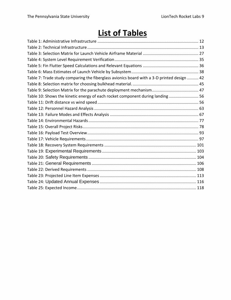
The Pennsylvania State University LionTech Rocket Labs 9
Table 1: Administrative Infrastructure ......................................................................................... 12
Table 2: Technical Infrastructure .................................................................................................. 13
Table 3: Selection Matrix for Launch Vehicle Airframe Material ................................................. 27
Table 4: System Level Requirement Verification .......................................................................... 35
Table 5: Fin Flutter Speed Calculations and Relevant Equations ................................................. 36
Table 6: Mass Estimates of Launch Vehicle by Subsystem ........................................................... 38
Table 7: Trade study comparing the fiberglass avionics board with a 3-D printed design .......... 42
Table 8: Selection matrix for choosing bulkhead material. .......................................................... 45
Table 9: Selection Matrix for the parachute deployment mechanism ......................................... 47
Table 10: Shows the kinetic energy of each rocket component during landing .......................... 56
Table 11: Drift distance vs wind speed ......................................................................................... 56
Table 12: Personnel Hazard Analysis ............................................................................................ 63
Table 13: Failure Modes and Effects Analysis .............................................................................. 67
Table 14: Environmental Hazards ................................................................................................. 77
Table 15: Overall Project Risks ...................................................................................................... 78
Table 16: Payload Test Overview .................................................................................................. 93
Table 17: Vehicle Requirements ................................................................................................... 97
Table 18: Recovery System Requirements ................................................................................. 101
Table 19: Experimental Requirements ................................................................................... 103
Table 20: Safety Requirements ............................................................................................... 104
Table 21: General Requirements ............................................................................................ 106
Table 22: Derived Requirements ................................................................................................ 108
Table 23: Projected Line Item Expenses ..................................................................................... 113
Table 24: Updated Annual Expenses ..................................................................................... 116
Table 25: Expected Income ......................................................................................................... 118
List of Tables

The Pennsylvania State University LionTech Rocket Labs 10
Section 1: General Information

The Pennsylvania State University LionTech Rocket Labs 11
1: Important Personnel Adult Educator Michael Micci - [email protected] - (814-863-0043)
Safety Officer Laura Reese - [email protected]
Team Leader Luke Georges - [email protected]
NAR Contact Alex Balcher NAR L2 Certification
- [email protected] - #96148SR
NAR Sections: Pittsburgh Space Command (PSC) #473
2: Team Roster and Structure Lion Tech Rocket Labs has approximately 88 active members, ranging from freshman to senior
undergraduates and graduate students. However, it is unexpected that all of these students will
be able come to the competition due to travel expenses and necessary accommodations. The
team is divided into administrative and technical branches for managing resources and
completing tasks.

The Pennsylvania State University LionTech Rocket Labs 12
Administrative The administrative branch is composed of the President, Vice-President, Treasurer, Secretary,
Outreach Chair, Webmaster and Safety Officer. These individuals are responsible for actively
providing space for the technical branch to be able to function and managing the team as a
whole. The position holder and their respective duties are shown in Table 1.
Table 1: Administrative Infrastructure
Name Position Proposed duties
Luke President Communicates with project stakeholders, organizes meetings and keeps team on schedule. Guides team in the overall design and construction of the systems.
Evan Vice President Assists President in managerial tasks, meetings with stakeholders and team. Coordinates integration between subsystems.
Justin Treasurer Arranges fundraising events, communicates with sponsors and manages funds for the project
Scott Secretary Records information discussed in meetings and communicates with the general body of the club in the form of reminders and meeting recaps via email
Brian Outreach Organizes events for the club to engage with the community and share experience, knowledge and passion in STEM fields
Tanay Webmaster Manages team website, uploads project deliverables and meeting notes
Torre Safety Officer Ensures team follows safety regulations and implements safety plan

The Pennsylvania State University LionTech Rocket Labs 13
Technical The technical branch is responsible for the design, fabrication, testing, and flight operations of
the payloads and flight vehicle. The technical branch is divided in to four main subsystems:
Avionics and Recovery, Payload, Propulsion, and Structures. Table 2 displays the officer
positions and subsystem duties within the technical branch. Because the team is large, a
description of what each subsystem’s duties are is given in place of a description of each
member’s duties. The officers themselves take a leadership role in the subsystems; they guide,
teach and work alongside their team to complete their duties. The general members of the club
are spread out among each of the four subsystems, under the technical officers.
Table 2: Technical Infrastructure
Position Duties
Evan A&R Leadership
Avionics and Recovery creates the avionics bay for the flight vehicle, tests altimeters, ejection charges and parachutes. On launch days A&R ensures proper parachute packing and successful vehicle recovery.
Gretha
Torre Payload Leadership
Payload designs and creates science packages for the project. These tend to involve computing and electrical components within the flight vehicle. Payload ensures these packages are functioning properly when preparing for launch.
Dan
Alex P. Propulsion Leadership
Propulsion selects motors for the vehicle, performs flight analysis and drag estimates. Propulsion is normally in charge of motor handling and insertion on launch days.
Kurt Structures Leadership
Structures designs and creates the flight vehicle, tests materials and ensures all necessary components of the vehicle are compatible and flight ready. Structures is in charge of final assembly of the rocket for launch.
Anthony
Kartik

The Pennsylvania State University LionTech Rocket Labs 14
Section 2: Summary of CDR Report
The Pennsylvania State University LionTech Rocket Labs 15
1: Team Summary Team – LionTech Rocket Labs
Address – 46 Hammond Building, University Park, PA 16802
Mentor – Alex Balcher – NAR L2 – #96148SR
2: Vehicle Summary Size and mass The current launch vehicle design will result in a launch vehicle with an overall length of 147
inches, and a total mass of 30.81 pounds without the motor and 38.69 pounds with the motor
at launch. These values are smaller than expressed in previous reports due to the shrinking of
several components, allowing for a reduction necessary airframe length. The outer diameter of
the airframe will be 6.079” and will be constructed out of Blue Tube 2.0.
Motor choice The motor selected for full scale is the Cesaroni L1350 motor. This motor provides the rocket
with an apogee of 5231 ft and an off the rail velocity and stability of 75.8 ft/s and 2.65 calibers
respectively.
Recovery system The recovery system will utilize a dual-deployment landing system where the drogue will be
deployed at apogee and the main will be deployed at 700ft above the ground. This landing
system along with properly sized parachutes will allow the rocket to land within the kinetic
energy limit of 75ft-lbs. The avionics bay consists of two independent altimeters with
corresponding power supplies, switches, and charges one of which will be for redundancy. In
order to not overwhelm the body of the rocket, one of the altimeters will set off the ejection
charges at a delay. The avionics bay will be contained in a coupler in the center of the rocket
with parachutes on both ends of it. The rocket will have an 18” Classical Elliptical as the drogue
parachute and a 72” Iris Ultra Standard as the main parachute.
Rail Size The launch vehicle will use a 1515 rail. It is capable of launching on an 8-foot launch rail,
however for safety and increased off the rail stability and velocity the rail length chosen is 12-
feet
3: Payload Summary Summary of the Payload Experiment The two payloads LTRL is flying in this competition are FOPS, Fragile Object Protection System,
and Kiwi, a gyrocopter.
FOPS uses a protection bay filled with non-Newtonian fluid, a solution of cornstarch and water, to
protect the unknown fragile object from the forces of rocket flight. The object will be
suspended in the fluid using flexible plastic, re-sealable bag connected to each end of the

The Pennsylvania State University LionTech Rocket Labs 16
protection bay via elastic bands. The launch vehicle will also contain and launch an autonomous
autogyro (Kiwi), which will guide itself to a predetermined location using an on-board GPS.
4: Milestone Review Flysheet
Milestone Review Flysheet
Institution Pennsylvania State University Milestone CDR
Vehicle Properties Motor Properties
Total Length (in) 147 Motor Manufacturer Cesaroni
Diameter (in) 6.079 Motor Designation L1350
Gross Lift Off Weigh (lb) 38.69 Max/Average Thrust (lb) Avg: 303.4
Airframe Material Blue Tube 2.0 Total Impulse (lbf-s) 962
Fin Material G10 FR4 Fiberglass Mass Before/After Burn 2616g/1270g
Drag 0.628 Liftoff Thrust (lb) 340
Stability Analysis Ascent Analysis
Center of Pressure (in from nose) 115 Maximum Veloxity (ft/s) 675
Center of Gravity (in from nose) 91.75 Maximum Mach Number 0.61
Static Stability Margin 3.8 Maximum Acceleration (ft/s^2) 259
Static Stability Margin (off launch rail) 2.65 Target Apogee (From Simulations) 5231
Thrust-to-Weight Ratio 7.83 Stable Velocity (ft/s) 95
Rail Size and Length (in) 1.5/144 Distance to Stable Velocity (ft) 3.5
Rail Exit Velocity (ft/s) 75.8
Recovery System Properties Recovery System Properties
Drogue Parachute Main Parachute
Manufacturer/Model Fruity Chutes Elliptical Manufacturer/Model Fruity Chute Iris Ultra
Size 18" Diameter Size 72" Diameter
Altitude at Deployment (ft) 5280 Altitude at Deployment (ft) 700
Velocity at Deployment (ft/s) - Velocity at Deployment (ft/s) 95
Terminal Velocity (ft/s) 95 Terminal Velocity (ft/s) 19.52
Recovery Harness Material Kevlar Recovery Harness Material Kevlar
Harness Size/Thickness (in) 0.5 Harness Size/Thickness (in) 0.5
Recovery Harness Length (ft) 30 Recovery Harness Length (ft) 40
Harness/Airframe Interfaces
1/2" Steel Eye Bolt
Harness/Airframe
Interfaces 1/2" Steel Eye Bolt
Kinetic Energy of
Forward Body Aft Body Section 3
Section 4
Kinetic Energy
Nose/Body Tube
Avionics Bay Booster KIWI

The Pennsylvania State University LionTech Rocket Labs 17
Each Section (Ft-lbs)
1651 2728
of Each Section (Ft-lbs)
51.42 49.64 52.44 9.22
Recovery Electronics Recovery Electronics
Altimeter(s)/Timer(s) (Make/Model) StratoLogger CF
Rocket Locators (Make/Model) Garmin Astro 320
Redundancy Plan
Single level redundancy for drogue and main
event
Transmitting Frequencies
MURS (151.820 MHz - 154.600 MHz)
Pyrodex Mass Drogue Chute (grams) 5
Pad Stay Time (Launch Configuration) 2 hours
Pyrodex Mass Main Chute (grams) 4

The Pennsylvania State University LionTech Rocket Labs 18
Section 3: Changes Made Since PDR

The Pennsylvania State University LionTech Rocket Labs 19
1: Vehicle Design Upon the transition from sub-scale to full-scale, several changes were made to the structure of
the rocket to boost stability and flight performance as well as contribute to structural integrity
sufficient for vehicle criteria. For example, fin shape was altered and fin brackets were designed
to best reduce the effects of fin flutter. Other changes were made to internal components such
as increasing the size of couplers to reduce the risk of failure at section interfaces. These
changes are elaborated upon in the upcoming design sections.
2: Recovery System General: The main changes since PDR are the sizes of the parachutes and the design of the avionics
board. The avionics board is now more compact and LTRL has confirmed the ability to
successfully 3-D print boards. The design of the board is included later in this report and
parachute sizing is also covered in depth.
Parachute Sizing: A more thorough look was taken at parachute sizing. The coefficients of drag used in the model
to predict the subscale flight recovery were found by doing simple drop test experiments with
the parachutes. However, these numbers proved to be inaccurate, as shown by the
comparison between the predicted descent profile and the actual descent profile of the
subscale launch. The parachute sizes are now smaller and will drift less.
Avionics Board: Since PDR, the design for the avionics board has been finalized. The final design for the avionics
board will consist of a 3-D printed board in a new configuration in order to account for design
concerns addressed in PDR. The new configuration is a triangular structure with three all-thread
rods in which the altimeters will rest on the top of a horizontal platform, while the batteries lie
underneath this platform. This configuration was decided upon in order to add additional
strength to the avionics coupler as a whole, by using three all-thread rods, as well as to hold all
components of the avionics board more securely. In addition, the plane that batteries are in is
now horizontal which eliminates the safety concern of the battery terminal being removed.
Specifically, this configuration will eliminate the concerns that launch and deployment event
forces can dislodge the battery terminals from the electrical harness.
3: Payloads The method of loading FOPS has been changed from inserting the specimen into a chamber
filled with dilatant to inserting the specimen into an empty chamber and then allowing an on-
board reservoir to fill the chamber. The second payload will be a gyrocopter instead of a coaxial

The Pennsylvania State University LionTech Rocket Labs 20
helicopter. The details of the new design can be found later in the report. Additional safety
features are included in the gyrocopter that were not included in the coaxial helicopter.
4: Project Plan The project plan has been updated to more accurately reflect the plans for the second half of
the project. In addition, the plan now has a greater level of detail compared to PDR. The
timeline now includes meeting times, as well as timelines for each subsystem rather than a
broad timeline for the entire project. The system level timelines provide more detail and better
represent the actual activities of the club. Furthermore, a Google Calendar was created for the
club. The calendar is accessible by all leads and allows them to record what was accomplished
in each meeting and plan what needs to be completed in future meetings. This will allow better
record keeping and for easier access to information pertaining to what each subsystem has
done and when.

The Pennsylvania State University LionTech Rocket Labs 21
Section 4: Design and Verification of the Launch Vehicle

The Pennsylvania State University LionTech Rocket Labs 22
1: Mission Statement LionTech Rocket Labs believes in providing an opportunity to be a part of high powered
rocketry and engineering design processes to any students who are interested, regardless of
background or experience.
LTRL is strives to excel in the USLI competition using previous experiences combined with new
innovations and ideas; however, the success of the organization is not directly tied to this.
Instead, the success of the organization is based on:
Members gaining valuable experience in rocketry, teamwork and outreach
Outreach activities spreading information about both the club and STEM fields
Conducting innovative design and research to improve the club and project
2: Final Design Decisions Motor Selection The motor selected for full scale is the Cesaroni L1350 motor. This motor was chosen because it
offers the closest apogee to the target apogee amongst the three candidate motors.
Furthermore, reliability and safety are two of the most important characteristics when selecting
motors, and based on prior experience and observation, Cesaroni motors have been consistent
in this regard.
The L1350, which is a 67% L-Class motor that utilizes a variant of ammonium perchlorate
composite propellant known as C-Star. The current weight of the rocket with the primary motor
inside of it is 619 oz and has a thrust to weight ratio of approximately 7.83.
The L1350 motor achieves a 5231 ft apogee and an off the rod velocity of 75.8 ft/s based on the
current rocket configuration in OpenRocket. This software is used as an estimate along with the
manufacturer motor specifications until the motor characteristics are clarified through static
motor testing at The Penn State University High Pressure Combustion Lab. Motor testing is
discussed in more detail in section 7.1. The manufacturer's thrust curve, as shown in Figure 1,
displays a thrust curve without any extreme peaks and maintains close to the average thrust of
approximately 303 lbs. This is a desired thrust curve because it will be easier to model due to
the lack of extreme peak thrust with respect to the average thrust. The thrust curve also
displays a total impulse of 962 lbf-s and an engine burn time of about 3.25 seconds.

The Pennsylvania State University LionTech Rocket Labs 23
Figure 1: Thrust Curve for the Cesaroni L1350 motor
Nosecone For the final design of the launch vehicle, the nosecone material was chosen to be
fiberglass. This is due to the fact that in comparison to plastic, fiberglass has superior durability
necessary to withstand both predicted and unforeseen forces that could act on the
nosecone. This superior durability and strength makes fiberglass the superior option, even
taking into account the increased cost and weight of the component. In addition, the nosecone
tip was chosen to consist of a separate aluminum component over an integrated fiberglass
tip. An aluminum tip has superior ductility and structural stiffness in comparison to a fiberglass
counterpart. In addition, a separate aluminum component would allow to easy replacement of
the component should it experience any structural or aerodynamic imperfections, instead of
having to replace the entire nosecone. The profile of the nosecone was chosen to be the Von
Karman shape over an ogive profile. This is due to the Von Karman’s mathematical formulation
to have a lower overall drag coefficient than an Ogive profile [1]. Because of this, the launch
vehicle has increased aerodynamic performance. The only drawback to the Von Karman profile
is its greater overall length in comparison, necessitating an increase in length and thus weight
of the nosecone component, but this consideration is well worth the decrease in drag
coefficient.

The Pennsylvania State University LionTech Rocket Labs 24
Figure 2: Von Karman Nose Cone Engineering Drawing
The dimensioned drawing of the nosecone is shown in Figure 2. The overall specifications for
nosecone are as follows:
5.5:1 length to diameter ratio
5.5-inch outer diameter
30.25-inch length
3-inch shoulder (5.4-inch diameter)
73-ounces (including all the components housed within nosecone)
Transitions and Acrylic The final material choice for both the nosecone to acrylic transition, and the acrylic to main
body tube transition, will be a 3D-printed PLA thermoplastic. No viable superior material option
to PLA thermoplastic was found for printing the components using the techniques of additive
manufacturing, or 3D-Printing. This was primarily due to the ease of manufacturing PLA
thermoplastic parts and the readily available resources for 3d-printing using PLA

The Pennsylvania State University LionTech Rocket Labs 25
thermoplastic. Experiences using PLA thermoplastic for components in the past year has
resulted in adequate durability and strength, given expected loads during flight and recovery.
Figure 3: Dimensioned Drawing of the Nose Cone to Acrylic Transition
The forward transition is shown and dimensioned in Figure 3. The specifications for this
transition are as follows:
1.5-inch exposed length
1.75-inch shoulder length
5.5-inch forward diameter and 5.75-inch max diameter
1.49 ounces
The acrylic section of the vehicle contains the FOPS payload assembly. It also contains the
transition stabilizing coupler made from blue tube 2.0. Refer to Figure 25 in the FOPS payload
description for renderings of the acrylic section. The specification for the acrylic section is as
follows:
12-inch length
5.75-inch outer diameter
The Pennsylvania State University LionTech Rocket Labs 26
65.9 ounces
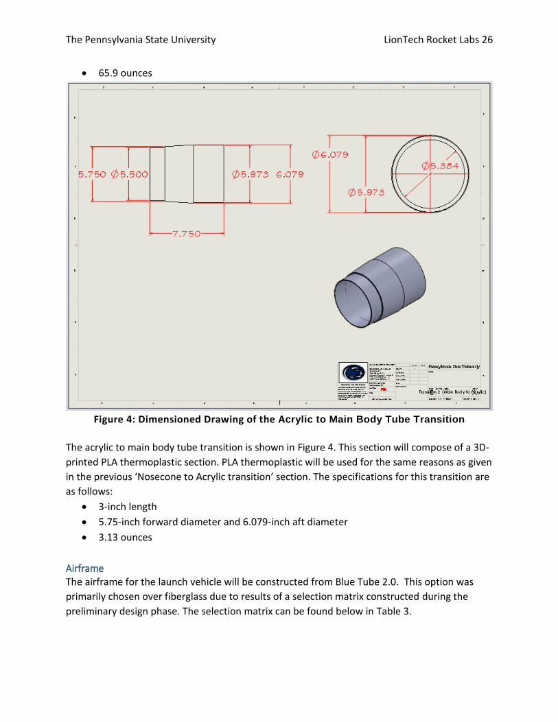
Figure 4: Dimensioned Drawing of the Acrylic to Main Body Tube Transition
The acrylic to main body tube transition is shown in Figure 4. This section will compose of a 3D-
printed PLA thermoplastic section. PLA thermoplastic will be used for the same reasons as given
in the previous ‘Nosecone to Acrylic transition’ section. The specifications for this transition are
as follows:
3-inch length
5.75-inch forward diameter and 6.079-inch aft diameter
3.13 ounces
Airframe The airframe for the launch vehicle will be constructed from Blue Tube 2.0. This option was
primarily chosen over fiberglass due to results of a selection matrix constructed during the
preliminary design phase. The selection matrix can be found below in Table 3.
The Pennsylvania State University LionTech Rocket Labs 27
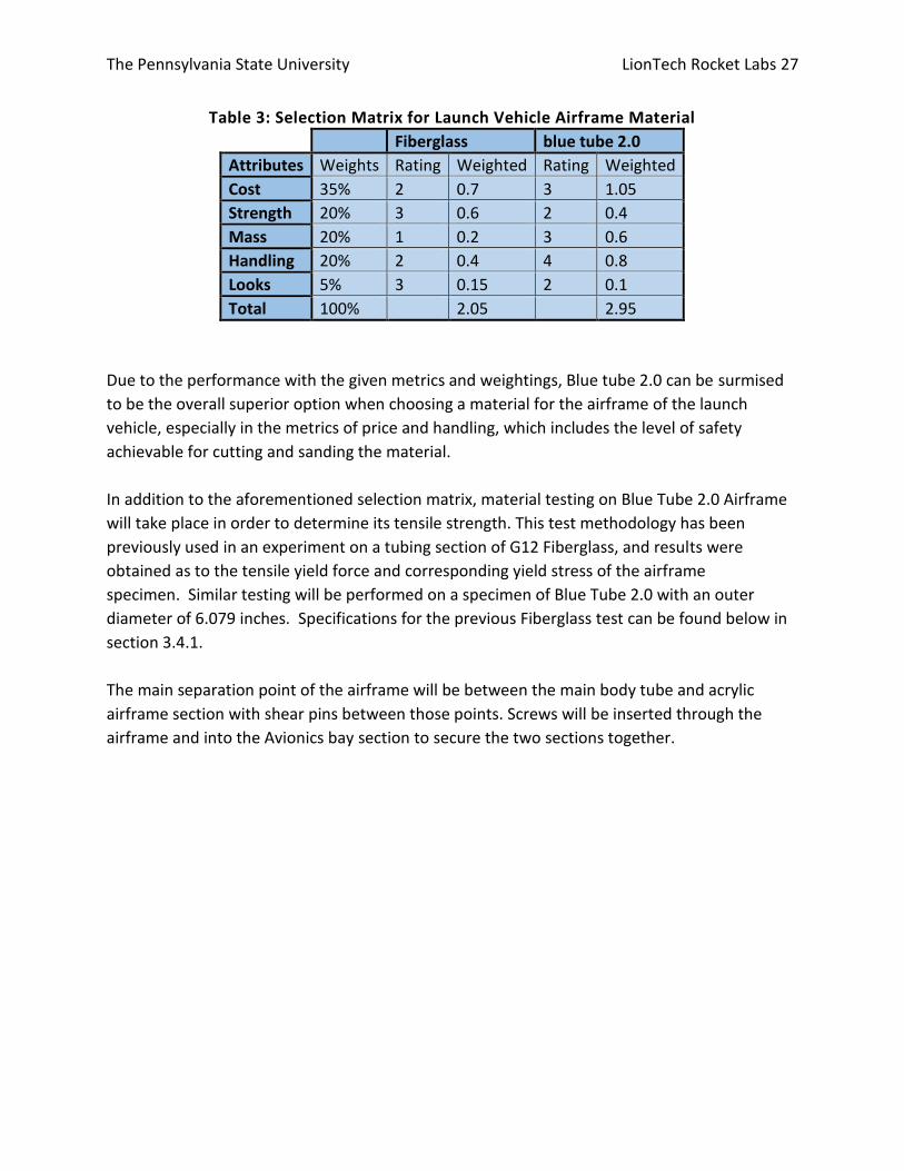
Table 3: Selection Matrix for Launch Vehicle Airframe Material
Fiberglass blue tube 2.0
Attributes Weights Rating Weighted Rating Weighted
Cost 35% 2 0.7 3 1.05
Strength 20% 3 0.6 2 0.4
Mass 20% 1 0.2 3 0.6
Handling 20% 2 0.4 4 0.8
Looks 5% 3 0.15 2 0.1
Total 100% 2.05 2.95
Due to the performance with the given metrics and weightings, Blue tube 2.0 can be surmised
to be the overall superior option when choosing a material for the airframe of the launch
vehicle, especially in the metrics of price and handling, which includes the level of safety
achievable for cutting and sanding the material.
In addition to the aforementioned selection matrix, material testing on Blue Tube 2.0 Airframe
will take place in order to determine its tensile strength. This test methodology has been
previously used in an experiment on a tubing section of G12 Fiberglass, and results were
obtained as to the tensile yield force and corresponding yield stress of the airframe
specimen. Similar testing will be performed on a specimen of Blue Tube 2.0 with an outer
diameter of 6.079 inches. Specifications for the previous Fiberglass test can be found below in
section 3.4.1.
The main separation point of the airframe will be between the main body tube and acrylic
airframe section with shear pins between those points. Screws will be inserted through the
airframe and into the Avionics bay section to secure the two sections together.

The Pennsylvania State University LionTech Rocket Labs 28
Figure 5: Dimensioned Drawing of the full-scale Vehicle Assembly
The full launch vehicle assembly is shown in Figure 5. The airframe aft of the acrylic to body
transition is split into several parts, the forward section, avionics bay, drogue section, drogue to
booster coupler, and the booster section.
The specifications for these sections are as follows:
Forward Airframe Section
28-inch length
6.079-inch outer diameter
59.7 ounces
Avionics Bay Coupler
4-inch length
6.079-inch outer diameter
66.5 ounces (mass includes all internal components)

The Pennsylvania State University LionTech Rocket Labs 29
Drogue Airframe Section
32-inch length
6.079-inch outer diameter
81.5 ounces
Drogue to Booster Coupler
12-inch length
5.973-inch outer diameter
11.7oz
Booster Section
32-inch length
6.079-inch outer diameter
135 ounces
Bulkheads and Centering Rings:
The bulkheads are made up of plywood and sequester sections of the launch vehicle. Because
of this thicker material choice, the higher surface area results in higher epoxy adhesion.

The Pennsylvania State University LionTech Rocket Labs 30
Camera cover:
Figure 6: Dimensional Drawing of the Down-Body-Camera Cover
The chosen camera cover is made of 3D-printed PLA thermoplastic and supports the camera
which sits externally on the rocket. There will be a small hole in the airframe to allow the
camera’s power and data wires to traverse inside the main body. A dimensional drawing of the
camera cover is shown in Figure 6.

The Pennsylvania State University LionTech Rocket Labs 31
Fin brackets: The fin brackets will be 3D printed and one is shown in Figure 7.
Figure 7: Dimensioned diagram of a Fin Bracket

The Pennsylvania State University LionTech Rocket Labs 32
Fins: Refer to Figure 8 for a dimensioned drawing of the fins. The specifications are as following:
3/16” thick
Fiberglass Construction
3 fins
Figure 8: Dimensioned drawing of a Fin
The Pennsylvania State University LionTech Rocket Labs 33
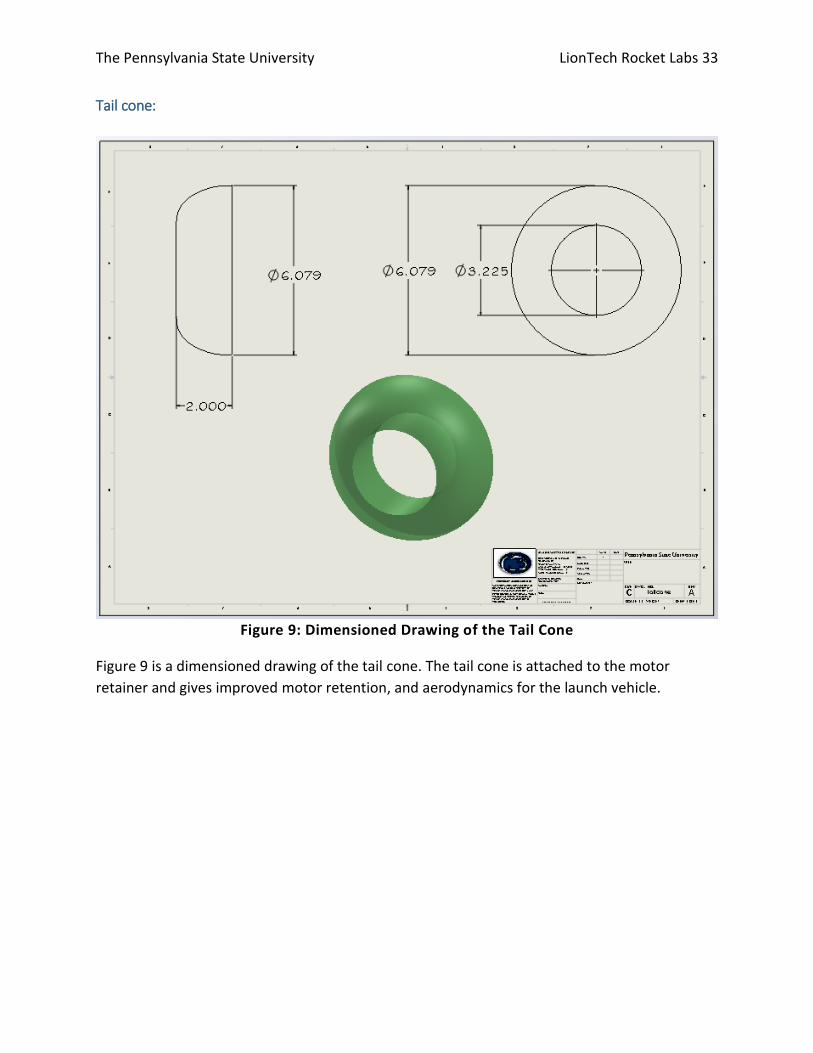
Tail cone:
Figure 9: Dimensioned Drawing of the Tail Cone
Figure 9 is a dimensioned drawing of the tail cone. The tail cone is attached to the motor
retainer and gives improved motor retention, and aerodynamics for the launch vehicle.

The Pennsylvania State University LionTech Rocket Labs 34
Figure 10: Comparison of Geometries and Comparable Drag Coefficients
A comparison of the fluid flow behind different geometries can be found in Figure 10. Without
a tail cone the launch vehicle is better represented by the rounded leading edge flat plate. With
the tail cone adding a rounded taper to the aft of the vehicle, the vehicles geometry becomes
closer to that of the elliptical rod. The elliptical rod has a 50% lower drag coefficient than the
rounded flat plate at a reference L/D of 4. Modeling both geometries gives similar results to
those shown in Figure 10, with a much lower coefficient of drag with a rounded trailing edge.
The Pennsylvania State University LionTech Rocket Labs 35
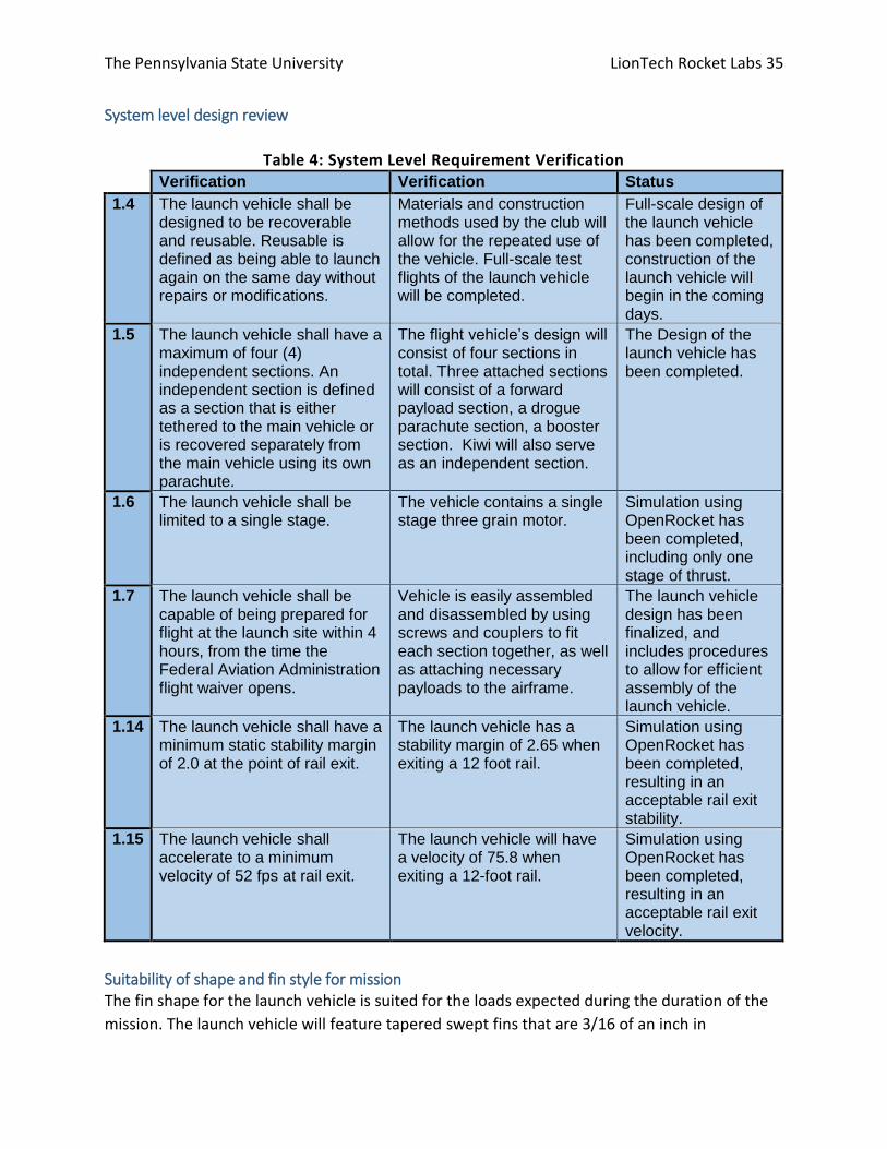
System level design review
Table 4: System Level Requirement Verification
Verification Verification Status
1.4 The launch vehicle shall be designed to be recoverable and reusable. Reusable is defined as being able to launch again on the same day without repairs or modifications.
Materials and construction methods used by the club will allow for the repeated use of the vehicle. Full-scale test flights of the launch vehicle will be completed.
Full-scale design of the launch vehicle has been completed, construction of the launch vehicle will begin in the coming days.
1.5 The launch vehicle shall have a maximum of four (4) independent sections. An independent section is defined as a section that is either tethered to the main vehicle or is recovered separately from the main vehicle using its own parachute.
The flight vehicle’s design will consist of four sections in total. Three attached sections will consist of a forward payload section, a drogue parachute section, a booster section. Kiwi will also serve as an independent section.
The Design of the launch vehicle has been completed.
1.6 The launch vehicle shall be limited to a single stage.
The vehicle contains a single stage three grain motor.
Simulation using OpenRocket has been completed, including only one stage of thrust.
1.7 The launch vehicle shall be capable of being prepared for flight at the launch site within 4 hours, from the time the Federal Aviation Administration flight waiver opens.
Vehicle is easily assembled and disassembled by using screws and couplers to fit each section together, as well as attaching necessary payloads to the airframe.
The launch vehicle design has been finalized, and includes procedures to allow for efficient assembly of the launch vehicle.
1.14 The launch vehicle shall have a minimum static stability margin of 2.0 at the point of rail exit.
The launch vehicle has a stability margin of 2.65 when exiting a 12 foot rail.
Simulation using OpenRocket has been completed, resulting in an acceptable rail exit stability.
1.15 The launch vehicle shall accelerate to a minimum velocity of 52 fps at rail exit.
The launch vehicle will have a velocity of 75.8 when exiting a 12-foot rail.
Simulation using OpenRocket has been completed, resulting in an acceptable rail exit velocity.
Suitability of shape and fin style for mission
The fin shape for the launch vehicle is suited for the loads expected during the duration of the
mission. The launch vehicle will feature tapered swept fins that are 3/16 of an inch in
The Pennsylvania State University LionTech Rocket Labs 36
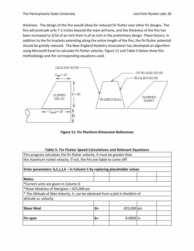
thickness. The design of the fins would allow for reduced fin flutter over other fin designs. The
fins will protrude only 7.1 inches beyond the main airframe, and the thickness of the fins has
been increased to 3/16 of an inch from ⅛ of an inch in the preliminary design. These factors, in
addition to the fin brackets extending along the entire length of the fins, the fin flutter potential
should be greatly reduced. The New England Rocketry Association has developed an algorithm
using Microsoft Excel to calculate fin flutter velocity. Figure 11 and Table 5 below show this
methodology and the corresponding equations used.
Figure 11: Fin Planform Dimension References
Table 5: Fin Flutter Speed Calculations and Relevant Equations
This program calculates the fin flutter velocity. It must be greater than
the maximum rocket velocity. If not, the fins are liable to come off!
Enter parameters: b,C,c,t,h – in Column C by replacing placeholder values
Notes:
*Correct units are given in Column D
*Shear Modulus of fiberglass = 425,000 psi
* The Altitude of Max Velocity, h, can be obtained from a plot in RockSim of
altitude vs. velocity
Shear Mod G= 425,000 psi
Fin span b= 8.0000 in

The Pennsylvania State University LionTech Rocket Labs 37
Root chord C= 11.0000 in
Tip chord c= 7.0000 in
Fin thickness t = t= 0.1875 in
Alt of Max V h= 3375 ft
Computations
**************************
S=0.5*(C+c)*b S= 72.0000
AR = ((b)^2)/S AR= 0.8889
r = c/C r = 0.6364
T=59-0.00356*h T= 46.9850
P(pressure) P= 13.0051
Sound speed a= 1103.8114 feet/sec
Denom1 [ = (1.337)*((AR)^3)*(P)*(1 + r) ] 19.9825
Denom2 [ = 2*(2+AR)*(t/C)^3) ] 0.00002861
**************************
Sound Speed*SQRT(G/(Denom1/Denom2))
Fin Flutter Velocity Vf = Vf = 861.1 ft/sec
Max Rocket Velocity MRV = MRV= 674 ft/sec
Fin Flutter Velocity Vf > MRV Maximum Rocket Velocity
Proper use of materials in fins, bulkheads, and structural elements
The materials used to construct the launch vehicle are appropriate in order to allow for mission
success. The main airframe sections, as well as coupler components, will be constructed from
Blue Tube 2.0, which will be able to provide ample structure to the launch vehicle and its
enclosed components. The Acrylic airframe section will have a ⅛ inch wall thickness, which will
give proper structure to the fore portion of the airframe and protect the FOPS payload. The
airframe transition components as well as the fin brackets will be created from 3D-printed PLA,
which through use on previous launch vehicles will be able to provide adequate resistance to
expected forces throughout the duration of the flight. Both internal and external bulkheads will
be constructed of birch plywood, and will provide capacious support when mounted to the
airframe and coupler components. Finally, the chosen fin material is G10 Fiberglass sheet which
will be 3/16 inches thick, which should provide sufficient structural integrity.

The Pennsylvania State University LionTech Rocket Labs 38
Verification of sufficient motor mounting and retention The motor mounting for the launch vehicle will be provided by a motor retainer and 3 centering rings spaced along the motor retainer for support. The motor retainer will be constructed out of Blue Tube 2.0, while the centering rings will be constructed out of birch plywood. There is not a motor retention block present in the final design since there will be a bulkhead placed in the aft portion of the camera section, which will be placed just fore of the motor retainer. This bulkhead will perform adequately in the role of a motor retention block in place of a dedicated motor retention block.
Mass Estimates Table 6 contains a list of mass estimations for everything making up the fully assembled launch
vehicle.
Table 6: Mass Estimates of Launch Vehicle by Subsystem
Part Mass (ounces) # of items sub-total mass
Structures
Nosecone with aluminum tip 40 1 40
Acrylic 18.2 1 18.2
Body tube, main 24.3 1 24.3
Body tube, drogue 27.7 1 27.7
Booster body tube 27.7 1 27.7
Bulkhead, inner transition 2.04 1 2.04
Bulkhead, inner 3.33 3 9.99
Bulkhead, outer 3.28 3 9.84
Transition, nose cone to payload 1.49 1 1.49
Transition, payload to main body 3.13 1 3.13
Transition stabilizing coupler 4.38 1 4.38
Coupler, drogue to motor 11.7 1 11.7
AV bay body tube 3.46 1 3.46
AV Bay coupler 16.4 1 16.4
Motor Inner tube 10.8 1 10.8
Centering ring 1.81 3 5.43
Fin set 43.3 1 43.3
Tail cone 6.66 1 6.66

The Pennsylvania State University LionTech Rocket Labs 39
Motor Retainer 1.89 1 1.89
Camera/cover 9.75 1 9.75
Ballast (10% Dry weight) 55 - 55
Hardware 12 - 12
Payload
Helicopter Payload 19 1 19
FOPS 40 1 40
Avionics & Recovery
Drogue Parachute 7.72 1 7.72
Shock cord, drogue 12 1 12
Avionics Bay 28 1 28
Shock cord main 16 1 16
Main parachute with blanket 19.4 1 19.4
GPS 6 1 6
Total (ounces) - 493
Total (pounds) - 30.81
3: Subscale Flight Results The subscale launch vehicle was tested on November 13th at the NAR certified Pittsburg Space
Command club field in Grove City PA. The temperature on that day was a high of 54 degrees
and low to intermediate erratic winds. Figure 12 shows the results of a simulation with these
conditions that yielded a similar flight profile to the actual flight data shown in Figure 13.

The Pennsylvania State University LionTech Rocket Labs 40
Figure 12: Altitude results from subscale simulation
Avionics Results A StratoLogger 100 model commercial altimeter was included in the avionics bay of the
subscale for deployment of the parachutes and for recording the flight profile. The altimeter
recorded a flight apogee of 2467 ft. A couple seconds after apogee the drogue deployed. The
momentum from the drogue deployment also deployed the main parachute. This was
attributed to using an insufficient number of shear pins on the main parachute coupler. Figure
13 shows the flight profile of the rocket during descent.
Figure 13: Flight Profile of the subscale during descent

The Pennsylvania State University LionTech Rocket Labs 41
The observed descent time was 95 seconds while the predicted descent time was around 85
seconds. The difference in these times may be accounted for by taking a closer look at the
coefficient of drag of the parachutes. It is likely that the parachutes coefficients of drag were
higher in reality than those used in the model.
The coefficient of drag used in the simulation for the drogue was 0.88. The coefficient of drag
for the main used in the simulation was 1.5. These were found by dropping objects with known
masses with these parachutes from a known height and observing the descent time. This
method of collection for the coefficients of drag lends to some inaccuracies. Therefore, for the
full scale, coefficients of drag will be determined by the manufacturer data or more careful
experimentation.
The issue of unintentional main deployment at apogee will be resolved by using more shear
pins and conducting more thorough ground testing.
Propulsion Results Using OpenRocket, the coefficient of drag was predicted to be 0.628 for both the subscale and
full scale rocket. The predicted apogee of subscale was 2969 ft, and the flight apogee was 2467
ft. There are several possible reasons for such a large discrepancy in the apogee such as winds
and last minute changes to the rocket. Due to this discrepancy it is unclear if the OpenRocket
coefficient of drag prediction is accurate or if any other prediction method would yield accurate
results without being able to account for more variables. Section 7.1 discusses another method
to experimentally determine the coefficient of drag.
Payload Results FOPS did not adequately protect the fragile object during the subscale launch. The design will
compensate for this failure by adjusting the shape of the plastic bag used so that the shape of
the bag fits better inside the protection chamber, minimizing additional stress caused by the
bag. An on-board reservoir will be used to fill the chamber after the insertion of the object(s).
Scaling Factors and Decisions When scaling the sub-scale up to full-scale, our scaling factors were determined based upon
manufactured blue tube and acrylic materials. The only variable held constant is the thickness
of the blue tube, again by virtue of manufactured pre-sets. Some altercations needed to be
made to the scaled fins to accommodate a new stability. Several of the internal components are
scaled as well, such as the Avionics Bay and Couplers.
Error between predictions and test results In terms of the vehicle’s structure and its effect on flight performance, error between actual
and predicted flight data is likely due to flight conditions or incorrect mass statements of
internal components still under construction such as our Kiwi payload. Some other sources of

The Pennsylvania State University LionTech Rocket Labs 42
error would be with additional weight of adhesives and fasteners, or imperfect (symmetrical)
geometry when manufactured.
Sub-scale flight and its effect on full-scale design The flight of our subscale launch vehicle and its flight data has confirmed our overall design.
With said data we are able to pursue full-scale design and flight projections.
4: Recovery Subsystem Components of the Recovery System The components of the recovery system are the avionics board, the avionics bay structure, the
parachutes and their corresponding harnesses, the altimeters, the faraday cage, and the
method of parachute deployment.
The altimeters and their corresponding power supplies are mounted onto the avionics board. In
previous competitions, A&R has used fiberglass sheets for the avionics board due to its strength
and durability. This comes at a cost of weight and safety hazards involved with cutting and
sanding fiberglass. An alternative to fiberglass is to 3-D print the board. The 3-D printed board is
significantly lighter and would be a more effective use of space. However, PLA, one of the
stronger and more common 3-D printing filaments, is susceptible to heat. Its glass transition
temperature is between 50 and 60 degrees Celsius [1], which the rocket can certainly reach on a
hot day in Alabama while waiting on the launch pad. Testing will have to be done to ensure
that the mechanical properties of PLA are still sufficient should the rocket reach these
temperatures. These two concepts are compared in Table 7, where the 3-D printed board edges
out the fiberglass board.
Table 7: Trade study comparing the fiberglass avionics board with a 3-D printed design
Fiberglass Board 3-D Printed Board
Category Weight Score Weighted Score Weighted
Cost 1 1 1 1 1
Legacy 1 3 3 1 1
Strength 3 3 9 2 6
Precision 3 1 3 3 9
Complexity 2 2 4 1 2
Mass 3 1 3 3 9
Thermal Resistance 2 3 6 1 2
Total 29 30
To test if an additively manufactured avionics board is viable, a small board was printed for use
on the subscale. This board performed without incident, verifying the choice of going with an

The Pennsylvania State University LionTech Rocket Labs 43
additively manufactured board. The full-scale rocket will use a 3-D printed board due to this
selection matrix and the success of the subscale launch. The 3-D printed boards are strong and
secure enough to withstand the forces exerted during the parachute deployment events and
the heat endured while waiting on the launch pad. The different design options are shown in
Figure 14 where the left is made out of fiberglass and the right is the 3-D printed board.

The Pennsylvania State University LionTech Rocket Labs 44
Figure 14: Fiberglass board (Left) vs 3-D printed board prototype (right)
Ultimately, a triangular design was created for use in the full scale. This design can be seen in
Figure 15.
Figure 15: Full-scale 3-D printed board

The Pennsylvania State University LionTech Rocket Labs 45
This triangular design was the result of over four design interactions and improvements. Early
problems with the printing of the material were overcome and the final design is compact, safe,
and highly integrated into the rocket. Figure 16 shows a successfully printed avionics board.
Figure 16: Full Scale 3-D Printed Avionic Board
Since the avionics bay will be housed in a coupler, there will be all-threads and bulkheads to
hold the avionics board in place and protect it from the ejection charges. There are two options
for the all-threads, aluminum and steel. Aluminum all-threads are lighter than steel but also not
as strong. In 2016, LTRL launched a rocket, Valkyrie, of similar height and weight using
aluminum all-threads. Hence, data from that launch can be used to determine if aluminum all-
threads are strong enough for this year’s rocket. Valkyrie also had a 120” diameter main
parachute. To find a conservative estimate for maximum force exerted on the avionics bay
during recovery, a scenario involving full and immediate main parachute deployment can be
used. Using Equation 1 [2] and assuming standard sea level conditions and a coefficient of drag
of 2, the drag of the parachute can be calculated to be 1045 lbf.
𝐷 = 1
2𝐶𝑑𝜌𝑉2𝜋𝑟2 (1)
The all threads must be capable of withstanding this force during deployment. Typically, two
⅜” all threads are used. The stress in each all thread can easily be calculated by dividing the
force by the area. This stress works out to be 4731 psi. This is far below the yield strength of
Aluminum 6061-T6 which is 40,000 psi [3]. This works out to be a factor a safety of
8.5. Therefore, Aluminum 6061-T6 will be used in the full-scale rocket.
For the bulkhead, the two options are wood and fiberglass. In most previous launches,
fiberglass bulkheads have been used. However, fiberglass bulkheads have several drawbacks
and wooden ones are better as long as they are strong enough. From previous launch data,

The Pennsylvania State University LionTech Rocket Labs 46
wooden bulkheads have been shown to be strong enough to withstand the forces from
parachute deployment. Using table 6, it is clear that wooden bulkheads are a better choice for
the rocket and hence they will be used in the full-scale rocket.
Table 8: Selection matrix for choosing bulkhead material.
Fiberglass Bulkhead Wooden Bulkhead
Category Weight Score Weighted Score Weighted
Cost 1 1 1 3 3
Legacy 1 3 3 3 3
Strength 3 3 9 2 6
Precision 3 1 3 2 6
Complexity 2 2 4 3 6
Mass 3 1 3 3 9
Total 23 33
The switches, altimeters, and the power supply are the avionics equipment. The two switches in
the full-scale rocket will be 1” diameter key switches. Those switches have been used in the
vast majority of rockets that LTRL has built in the past two years and have never failed. The
wires that connect the key switches to the altimeters will be soldered onto the key switches to
ensure that they remain connected. The altimeters used will be two SL CF altimeters because of
their reliability, ease of use, and affordability. These are an upgraded model of the previous
altimeters LTRL has used which were the StratoLogger SL 100 altimeters that were very reliable
and lead to many successful launches. The SL CF altimeters weigh 0.07 ounces [4]. Each
altimeter will use a fresh 9V battery as its power supply.
The Faraday Cage is a crucial component of the avionics coupler because it protects the
electronics in the avionics bay from any interference. This prevents the accidental deployment
of the separation charges at the launch pad around other rockets. Traditionally, that Faraday
Cage was a thin mesh metal sheet that was rolled and fit into the coupler. However, this made
it difficult to access the avionics equipment and attach the key switch. It would also scratch the
avionics bay and any hands that tried to adjust the bay. For the full-scale rocket, there will be a
3-D printed sleeve that a thin sheet of aluminum can slide into and remain undisturbed (Figure
17). The sleeve allows the assembly of the avionics bay and coupler to be easier and ensures
that the Faraday Cage is not shifted. Additionally, the bulkheads will have a layer of aluminum
on the inside to further protect the electronics.

The Pennsylvania State University LionTech Rocket Labs 47
Figure 17: Sleeve for Faraday Cage Assembled Avionics Bay
The parachutes chosen for the full-scale rocket are an 18” Fruity Chutes Classic Elliptical for the
drogue parachute and a 72” Fruity Chutes Iris Ultra Standard for the main parachute. These
parachutes were chosen because they will allow the rocket to descend within the kinetic energy
limit of 75 ft-lbs without drifting more than 2500’. More information about the parachute
selection is in the following section, Parachute Sizing Estimation.
The rocket separation points in the full-scale rocket are fixed to the interface between the body
and the nose cone and the interface between the bottom body tube and the booster
section. This is opposed to the separation points being located at points directly adjacent to
the avionics bay. The reason these separation points are chosen to for parachute ejection
assurance. If the separation points are adjacent to the avionics bay, then the separation
charges, located on the bulkheads of the avionics bay, will push the parachute further into the
body tubes. While the velocity of the components separating most likely will pull the parachute
out, this is an additional risk that can be avoided by placing the separation points at the right
locations. The separation points could be located adjacent to the avionics bay if dangling
charges are used to ensure the charges force the parachute from the body tube, but this
method also has added complications, especially during assembly. An additional advantage of
having one of the separation points at the interface between the booster section and the body
tube is that the body tube remains connected to the avionics bay instead of the booster
section, which is usually one of the most massive parts of the rocket already, thus reducing the
necessary parachute size to maintain a safe landing velocity.
The last major recovery system component is the parachute deployment mechanism. The main
choices for this component are black powder ejection, Pyrodex ejection, and CO2 cartridge
ejection. Each system has its own advantages and disadvantages and are weighed in Table

The Pennsylvania State University LionTech Rocket Labs 48
9, which highlights the selection process of the deployment mechanism based on various
important selection criteria.
Table 9: Selection Matrix for the parachute deployment mechanism
Black Powder Pyrodex CO2 Cartridge
Category Weight Score Weighted Score Weighted Score Weighted
Cost 1 3 3 3 3 2 2
Legacy 3 3 9 2 6 1 3
Reliability 3 3 9 2 6 2 6
Member Experience
2 3 6 2 4 1 2
Form Factor 1 2 2 2 2 1 1
Complexity 2 3 6 2 4 1 2
Safety 3 1 3 2 6 3 9
Total 38 31 25
The full-scale rocket will use black powder because of its reliability and the team’s familiarity
with it. The team has calculated the amount for black powder needed for each section using
models but will confirm if it is the proper amount through ground tests and test launches.
Parachute Size Estimation The parachute size needed to safely land the rocket while remaining below the kinetic energy
limit can easily be calculated using Equation 2.
𝑉 = √2 ∗ 𝐾𝐸
𝑚(2)
𝐷 = √𝑀𝑚𝑀𝑡𝑔
𝐶𝑑𝐾𝐸𝜌𝜋(3)
Then, this velocity can be inserted into the terminal velocity equilibrium equation, Equation 3,
to find the diameter needed for the main parachute. The computer calculations used to find
the necessary diameters is shown in Appendix A: MATLAB Recovery Model.

The Pennsylvania State University LionTech Rocket Labs 49
Figure 18 shows the plot for necessary diameter of the main vs. kinetic energy at landing
calculated with the MATLAB code.

The Pennsylvania State University LionTech Rocket Labs 50
Figure 18: Diameter of the main parachute vs. desired kinetic energy at landing
Proof of Redundancy The avionics system design includes multiple layers of redundancy. First and foremost, there
are two altimeters. Each altimeter is linked to its own separate main and drogue charge. Each
altimeter is also powered by its own battery. Therefore, even with the failure of a battery,
altimeter, e-match, or charge ignition in one of the systems, the other system is completely
independent and should still operate correctly. The deployment charges are also staggered so
that they do not go of simultaneously, a precaution taken to avoid overpressure events. The
redundancy ensures that the parachutes will deploy and that the rocket will not have ballistic
descent.
5: Mission Performance Predictions Motor Performance Analysis Figure 19 shows the flight profile simulation from ignition to landing. The altitude, vertical
velocity, and vertical acceleration are simulated over time. In Figure 19, it can be observed that
the predicted altitude will be just under 5250 ft, this apogee prediction includes the maximum
ballast weight allowed in the rocket. Which, will allow for fine tuning the apogee if there are
greater winds than in the model, which were 4.47 mph with a small average deviation and
medium turbulence level.

The Pennsylvania State University LionTech Rocket Labs 51
Figure 19: Full-scale Flight Simulation
It is known that OpenRocket over-predicts drag during simulations, therefore it can be assumed
that the actual apogee would be higher. Two methods will be used to compensate for this over
prediction, discussed in section 7.1.
Figure 20 shows the OpenRocket simulation for the L1350 motor thrust curve. It can be
observed that features in Figure 20 resemble those in the manufacturers thrust curve in Figure
1. For example, the time and magnitude of peak thrust in both plots are between 1500 and
1550 Newtons at 1 to 1.25 seconds. Additionally, there are similar distinct graphical features
such as the spike at ignition which both show to be approximately 1500 Newtons. Finally, there
is a second feature at approximately 2.75 seconds which shows the thrust approaching a
constant value of about 1300 Newtons before quickly decreasing. These multiple correlations
show reasonable agreement between the provided information and the predictions.

The Pennsylvania State University LionTech Rocket Labs 52
Figure 20: OpenRocket Thrust Curve Simulation
Stability Analysis The current OpenRocket model has a calculated center of gravity location about 91.75 inches
from the tip of the nosecone and a center of pressure of 115 inches from the nose cone, as
seen in Figure 21.
Figure 21: Full-scale OpenRocket Model
This puts the center of gravity about 23.25 inches forward of the center of pressure, which
corresponds to a static stability margin of 3.8 calibers, 2.65 calibers off a 12 ft launch rail and
2.56 calibers off an 8 ft launch rail. Figure 22 and Figure 23 describes the center of gravity,
center of pressure, and the stability margin from lift off until the stability becomes relatively
constant when launched from 12 ft or 8 ft launch rails respectively.

The Pennsylvania State University LionTech Rocket Labs 53
Figure 22: Full-scale OpenRocket Stability Simulation for 12 ft rod

The Pennsylvania State University LionTech Rocket Labs 54
Figure 23: Full-scale OpenRocket Stability Simulation for 8 ft rod

The Pennsylvania State University LionTech Rocket Labs 55
Recovery Predictions Recovery predictions were made using a computer program developed to estimate necessary
parachute sizes and calculate the descent profile of a rocket based on mass and parachute
characteristics. This program, dubbed the Recovery Descent Profile Calculator (RDPC) is written
in MATLAB and uses a force balance integration method to calculate a descent profile. At each
time step, the altitude and velocity are used to find the force of drag the parachutes are
exerting on the rocket system. This drag force and the force of gravity are then summed to get
a net force, from which the acceleration can be calculated. This acceleration is used to find a
velocity at the next time step, after which the process continues until the rocket hits the
ground.
Using the selected parachute sizes, RDPC was used to estimate the descent profile of the
rocket. Figure X shows the estimates velocity and altitude vs time during descent for the main
rocket body.
Figure 24: Descent profile of the rocket from RDPC
Kinetic Energy Calculations Each section of the rocket landing independently is required to have a kinetic energy less than
75 ft-lbs. There are four main components of the rocket that will be landing
independently. The mass of each component, the velocity upon landing, and the kinetic energy
upon landing calculated from RDPC is shown in Table 10. The Nose Cone, Avionics Bay, and

The Pennsylvania State University LionTech Rocket Labs 56
Booster section will be tethered together and attached to the drogue and main parachute
during descent. Kiwi will descent under autorotation of the blades until it reaches 500 feet, at
which time the parachute will deploy. Kiwi’s landing velocity will be 25.2 feet per second and
the kinetic energy of Kiwi will be 9.22 ft-lbs. The highest kinetic energy at landing is the booster
section, which will land with approximately 52.44 ft-lbs of energy.
Table 10: Shows the kinetic energy of each rocket component during landing
Nose Cone &
FOPS
Avionics Bay/ Middle
Section
Booster
Section
Kiwi
Mass (oz) 139 134 142 17
Landing Velocity (ft / s) 19.52 19.52 19.52 25.17
Landing Kinetic Energy
(ft-lbs) 51.42 49.64 52.44 9.22
Drift Calculations The RDPC also calculates the drift distance that the rocket will undergo in certain wind
conditions ranging from 0 to 20 mph winds. The main and drogue parachutes were specifically
selected to keep the drift within 2500 ft under all wind conditions. Table 11 shows the drift
calculated by RDPC during descent under different wind conditions.
Table 11: Drift distance vs wind speed
Wind Speed (mph) 0 5 10 15 20
Drift Distance (ft) 0 559.7 1119 1679 2239

The Pennsylvania State University LionTech Rocket Labs 57
Section 5: Safety

The Pennsylvania State University LionTech Rocket Labs 58
1: Launch Concerns and Operation Procedures Recovery Preparation Checked and initialed by two Recovery subsystem members and the Safety Officer after
completion
Key Switch ..................................................................................................................... OFF Position
Batteries ..................................................................................................................................... OUT
Bay ............................................................................................................................................ Wired
Batteries ............................................................................................................................... Installed
Bay .................................................................................................................................... Assembled
E-matched ........................................................................................................................ Assembled
Gun Powder ...................................................................................................................... Measured
Note: Drogue - 4.0 grams black powder
Main – 5.0 grams black powder
Measured Charge ................................................................................................ Added to blast cap
Wadding .............................................................................................................. Added to blast cap
Recovery Harness ............................................................................................................. Assembled
Parachutes ............................................................................................................................. Folded
Nomex Blankets ................................................................................................ Fixed to Shock Cord
Folded Chute ..................................................................................................................... Powdered
Recovery Harness and Chutes .................................................................... Inserted into body tube
Rocket .............................................................................................................................. Assembled
Shear Pins ............................................................................................................................. Installed
Recovery Subsystem Members Safety Officer
__________ __________
__________

The Pennsylvania State University LionTech Rocket Labs 59
Structures Preparation Checked and initialed by two Structures subsystem members after completion
Rail Buttons ............................................................... Aligned and secured to airframe using screw
Avionics Bay ..................................................Fastened to Main and Drogue Sections Using Screws
FOPS ............................................................................................ Placed in Acrylic Airframe Section
Nose Cone ............................................................................. Screwed to Acrylic Transition Coupler
Acrylic to Main Transition .................................................................. Shear pinned to Main Section
Booster Section ........................................................................ Shear pinned to the drogue section
Motor Retainer .................................................................................................... Screw on tail cone
Visual Inspection ............................................................. Screws tightened and assessed for cracks
Structures Subsystem Members
__________ __________
FOPS Launch Checklist Checked and initialed by two Payload subsystem members after completion
Materials Bag .......................................................................................................................... Sealed
Dilatant ......................................................................................................................... Fills Chamber
Chamber .................................................................................. Checked for leaks, bolts are secured
Chamber ................................................ Secured into rocket (Structures Lead Signature required)
Payload Subsystem Members
__________ __________
Structures Lead
__________

The Pennsylvania State University LionTech Rocket Labs 60
Kiwi Launch Checklist Electrical Connections .............................................................................................................Secure
Kiwi Vehicle ............................................................ Assembled (Payload Lead Signature Required)
Power switch ........................................................................................................ in the ON Position
Warning: Next step involves explosives and should be conducted away from bystanders
and under the supervision of an experienced team member. Wear safety goggles.
Parachute ................................................................................................................................ Tested
Parachute .................................. Folded correctly and stowed (Payload Lead Signature Required)
WARNING: INCORRECTLY STOWING PARACHUTE MAY LEAD TO UNCONTROLLED DESCENT
Parachute Door .................................................................................................. Latched and secure
Radio .......................................................................................................... Connection Established
Rotors .................................................................... Unobstructed by the padding and vehicle walls
Kiwi vehicle .............................................................. Properly padded and inserted into the rocket
Kiwi vehicle .......................................................................................................................... Secured
Payload Subsystem Lead
Vehicle: __________ Parachute: __________

The Pennsylvania State University LionTech Rocket Labs 61
Motor Preparation Checked and initialed by one Propulsion subsystem member and one NAR certified member
Smoke Trail Grain Assembly ................................................................ Loaded into forward closure
Forward Closure ....................................................................................................... O-Ring inserted
Nozzle Holder .......................................................................................................... O-Rings inserted
Nozzle ..................................................................................................... Inserted into nozzle holder
Lower Retaining Ring ............................................................................ Sealed on bottom of casing
Nozzle/Nozzle Holder Assembly ........................................................................ Inserted into casing
Casing Liner ........................................................................................................ Inserted into casing
Motor Grains (3) ............................................... Inserted into casing liner and spaced with O-rings
Forward Insulating Disk .................................................................................... Inserted into casing
Forward Closure/Smoke Trail Grain Assembly ................................................. Inserted into casing
Upper Retaining Ring ................................................................................... Sealed on top of casing
Closure Wrench ............................................................. Used to firmly tighten both retaining rings
Motor Casing ........................................................................................... Installed in motor retainer
Exterior Closure ......................................................................................... Sealed on base of casing
Propulsion Subsystem Member NAR Certified Member and Cert Level
__________ __________ __________
Setup on Launcher Rail ............................................................................................................ Pull to horizontal position
Rail .................................................................................... Clean with WD 40 before placing Rocket
Rocket ......................................................... Slide the rail buttons carefully through the rail guides
Launcher ............................................................... Set the rail with the Rocket to the desired angle
Motor ........................................................................................... place the charges into the motor
Ignition Insertion Performed by one Propulsion subsystem member and one Propulsion subsystem lead.
E-match ................................................................................... Twist the leads together if not done
Ignition circuit ......................................................................... Check to make sure it is deactivated
Nozzle Cap .................. Thread E-match ignition end through the side hole, from outside to inside
E-match ....................................................................... Feed through nozzle up to top of the motor
Nozzle Cap ....................................................... Place over end of nozzle, securing E-match in place
E-match leads ................................................... Separate two leads to at least one foot in distance
E-match leads .................................................................... Connect each lead to the ignition circuit
E-match leads ...................................................... Ensure that the leads will not contact each other

The Pennsylvania State University LionTech Rocket Labs 62
Troubleshooting
Problem Resolution
Altimeter does not turn on
1. Put key switch in off position and try to turn it on again. If it still does not turn on, go to step 2.
2. Disconnect and reconnect the power supply and all of the wires connected to the power supply and key switch. Then turn the key switch into the on position. If it still does not turn on, go to step 3.
3. Replace the altimeter. There will be several back-ups on launch day.
Altimeter does not emit continuity beeps
1. Turn the altimeter off and on again and wait for continuity beeps. If it still does not emit continuity beeps, go to step 2.
2. Ensure that the altimeter is wired correctly and has power. If it still does not emit continuity beeps, go to step 3.
3. Remove and replace the altimeter.
Parachute does not fit in rocket
1. Unpack the parachute 2. Pack the parachute more tightly 3. Cover the parachute with Nomex chute protector 4. Apply baby powder onto the chute protector 5. Place parachute and the chute protector in the rocket
Failure to ignite. 1. Wait for the RSO to give the all clear. 2. Remove AND Disconnect the E-match. 3. Check launch circuit for continuity. 4. Inspect the E-match. 5. If the E-match ignited disassemble the motor while checking to
see if it was correctly assembled. 6. Inspect the fuel grains for damage or irregularities. Replace if
necessary. 7. If no problem was found consider consulting the RSO or the
mentor. 8. Reassemble and reinstall the motor. 9. Try launching again.
Motor cannot be properly assembled
1. Fully read the instructions twice. 2. Completely disassemble the motor. 3. Reassemble the motor step by step exactly as the instructions
state. 4. If problem persists contact the RSO/Mentor/Motor Vendor.

The Pennsylvania State University LionTech Rocket Labs 63
Post flight inspection 1. Read the maximum altitude and velocity from the altimeters at landing
2. Confirm that the altimeters have consistent data
3. Make sure parachutes are not damaged from the ejection charges
4. Make sure all ejection charges have detonated
5. Connect altimeters to a computer and ensure that the flight when as predicted
6. Understand and explain any variations from the modeled flight path
2: Safety and Environment Personal Hazard Analysis All team members have taken Penn State’s lab safety course containing information safety
regulations for working with hazardous materials. Safe working habits will be enforced when
working on any project. The team safety officer is responsible for ensuring all team members
are informed of any hazards and abide by the guidelines for accident avoidance.
Safety procedures were developed by consulting the Material Safety Data sheets (MSDS)
attached to the end of this report. All NAR regulations pertaining to high power rocket safety
are followed. Operator’s manuals are also available to members to consult prior to using any
unfamiliar equipment. More experienced individuals will be in the lab during construction, so
no one is ever in a situation where they are unsupervised while using a tool for which they
are not properly trained to use.
Table 12 shows the hazards that may be encountered during this project, their respective
mitigations and the verifications for the mitigation. The likelihood and impact of each hazard
is ranked on a scale of 1-5. The necessary PPE for hazard mitigation have been purchased,
and their locations are known to team members. As part of launch day activities, all team
members present are informed of potential safety issues at high-power rocket launches,
proper safety oriented conduct and range safety regulations.
Table 12: Personnel Hazard Analysis
Hazard Cause Effect Likelihood
Severity
Mitigation Verification
Blue tube and sheet machining and sanding
Inhalation of small particulates
Dust particles can cause respiratory irritation and damage
3 2 Use face mask and shop vacuum, maintain adequate ventilation
Visual verification prior to machining or sanding

The Pennsylvania State University LionTech Rocket Labs 64
Power Tool Use
Flying debris
Cuts, possible eye injury
2 3 Wear safety glasses, follow tool safety instructions
Visual Verification and education of team members about possible precautions
Solder iron use
Tip of solder iron becomes very hot
Personnel are burned, Potential fire hazard if left on near flammable
1 3 Personnel will be instructed in safe use before soldering. Solder iron should not be left on unattended
Verify that personnel have been trained in solder iron use. Verify whether solder iron is hot before leaving room.
Black Powder
Material is a fire hazard and explosive
Fire, personal injury, equipment damage
2 5 Only qualified people are permitted to handle these materials. Use only in small quantities and away from sparks and statics.
Secure Black powder so that only the qualified personnel have access.
Pyrodex Material is a fire hazard and explosive
Fire, personal injury, equipment damage
1 4 Only qualified people are permitted to handle these materials.
Secure Pyrodex so that only qualified personnel have access.

The Pennsylvania State University LionTech Rocket Labs 65
Use only in small quantities and away from sparks and statics.
Spray paint use
Inhalation of aerosol and solvent vapors
Skin and or respiratory irritation
2 2 Use PPE and adequate ventilation
Visual PPE inspection, use of specialized painting booth on campus
Use of adhesives (e.g. JB Weld)
Inhalation of solvent vapors
Respiratory irritation
2 2 Use PPE and adequate ventilation
Visual PPE inspection
Motor misfire
Possible unexpected explosions
Personal injury, equipment damage
1 5 Wait for a safe period of time, disarm ignition sources.
Ensure that the motor is inserted properly.
Unfired ejection charges after launch
Possible unexpected explosions
Personal injury, equipment damage
1 5 Ensure that ignition charge is inserted properly and connected securely. Ensure altimeters are working correctly
Verify that ignition charge is inserted properly and connected securely. Verify altimeters are working correctly
Pre-firing of ejection
Possible unexpecte
Personal injury,
1 5 Ensure no one is
Verify no one is

The Pennsylvania State University LionTech Rocket Labs 66
charges prior to launch
d explosion
equipment damage
standing behind or in front of rocket once charges have been placed in the rocket. Ensure that ignition charge is inserted properly and connected securely. Ensure altimeters are working correctly
standing behind or in front of rocket once charges have been placed in the rocket. Verify that ignition charge is inserted properly and connected securely. Verify altimeters are working correctly
Unstable or dangerous rocket flights at launches
Rocket hitting personnel or equipment
Injury to personnel or equipment
2 5 Obey launch officials, pay attention during launch, pre-launch safety briefings
Use the preflight and launch safety checklists.
Improperly loaded equipment during transport
Equipment moves during transport
Damage to equipment, possible injury to personnel
2 3 Proper packaging and securing of all transport equipment
Use the packing check list.
Rockets may fall without
Rockets have high kinetic
Damage to equipment,
1 4 Instruct all personnel on launch
Verify all personnel understand

The Pennsylvania State University LionTech Rocket Labs 67
parachute deployment at launches
energy due to lack of parachute deployment
injury to personnel
day safety, keep equipment and vehicles a safe distance from the launch pad
launch day safety before taking them to a launch. Verify all equipment and vehicles are stored a safe distance from the launch pad.
Failure Modes and Effects Analysis To ensure a safe and effective launch, an assessment of possible failures has been made. By
analyzing the cause of the failure, precautionary steps will be taken to reduce the risk of failure.
Table 13 shows the preliminary set of failure modes. The likelihood and impact of each failure
mode is ranked on a scale of 1-5.
Table 13: Failure Modes and Effects Analysis
Failure Mode
Cause Effect Likelihood
Impact
Mitigation Verification
Rocket
Motor does not stay retained
Ejection charges push motor out of rear of rocket
Motor does not remain in rocket
1 5 Use of active motor retention, Use of lower impulse motor
Computer modelling and full scale test
Cascading fracture of body tube
Body tube fractures due to extreme stress around bolt hole
Catastrophic failure of airframe
1 4 Simulation of expected stresses, materials testing
Compare the simulations to the Tensile test results
Crack along outer
Body tube cracks due to torsional stress and
Functional / structural inadequacy
2 3 Reducing the stress concentration
Simulation of expected stresses,

The Pennsylvania State University LionTech Rocket Labs 68
seam of body tube
bending moment
materials testing
Unwanted separation of coupler from body tube
Premature shear pin failure
Undeployed parachutes, uncontrolled descent
3 2 Screw adequate number of screws
Visual inspection , pre-flight check
Fracture crack in coupler
Torsional stress and/or bending moment
Aerodynamic inconsistency and/or structural failure
2 2 Simulation of stresses, materials testing
Visual inspection , pre-flight check
Nosecone tip removal
Extreme impact
Aerodynamic instability, instability, sky debris
1 4 Simulation of expected stresses, material testing
Pre Flight check
Fin fracture crack
Extreme or repeated impact, bending moment
Aerodynamic instability, structural failure
2 2 Simulation of expected stresses, material testing
Visual inspection , pre-flight check
Fins separate from the fin brackets
Insufficient epoxy strength, loosening of bolts
Sky debris 1 5 Epoxied well with the fin brackets
Simulation of expected stresses, material testing, pre-flight check
Fin brackets loosening from the body tube
Insufficient epoxy strength
Aerodynamic instability, structural failure
1 3 Screwed and epoxied adequately
Visual inspection, pre-flight check
Fin brackets separate from body tube
Insufficient epoxy strength
Sky debris 1 5 Removing the dust from the body tube before epoxying
Simulation of expected stresses, materials testing, pre-flight check
Fracture crack in bulkheads
Material Defect, stress on eyebolt
Structural Failure,
2 5 Simulation of expected stresses,
Visual Inspection,

The Pennsylvania State University LionTech Rocket Labs 69
threads, insufficient epoxy strength
pressure leakage
material testing
Pre-flight check
All-threads shear
Insufficient all thread strength
Unwanted separation of rocket
1 5 Simulation of expected stresses, visual Inspection
Pre-flight check
Airframe zippers
During ejection shock cord cuts into body tube
Rocket body is damaged
2 3 Deploy parachute precisely at apogee with altimeters
Computer modelling and motor testing to confirm the motor thrust characteristics
Fin flutter Width of fins is too small
Aerodynamic instability, structural failure
2 3 Increase in width of the fins
Simulation of expected stresses
Payload
Payload causes sudden change in center of gravity for the rocket
Shifting shear thickening liquid causes a sudden change in center of gravity for the rocket
Rocket becomes unstable
1 3 A set amount of shear thickening liquid will be used. Any liquid will be suspended in the center of the fragile materials protection bay.
FOPS will be flown in test rocket launches to ensure it does not affect the center of gravity.
Kiwi loses balance and is no longer able to sustain flight
Kiwi loses balance
Kiwi guided section free falls to the ground
3 4 Kiwi will be made with an overall density low enough to ensure a low terminal velocity during free fall. The design of Kiwi will use ballast
Kiwi will undergo multiple test flights with different starting orientations to ensure that the vehicle can

The Pennsylvania State University LionTech Rocket Labs 70
to prevent sudden attitude change
reach and maintain stability.
Drive Shaft failure occurs while Kiwi is in flight
Drive shaft failure
Kiwi guided section falls under parachute to the ground
2 4 Kiwi will be equipped with a parachute that will ensure the vehicle meets kinetic energy requirements
Parachute testing will be performed to ensure the vehicle will meet Kinetic energy requirements.
Kiwi loses GPS contact
Kiwi loses GPS contact
Kiwi guided section does not reach proper location
1 5 In case of directional failure, Kiwi will be programmed to descend at a low velocity and be equipped with a tracking GPS
Test the range of the tracking GPS and test the GPS failure mode of the Kiwi flight computer.
Kiwi loses contact with Ground Station
Communication Failure
Kiwi cannot be shut down in case of emergency
2 3 If Kiwi loses contact with the Ground Station, it will deploy its parachutes and shutdown.
Kiwi’s communication systems will be tested at extreme ranges
Kiwi gets tangled in parachute cords
Kiwi gets tangled in parachute cords
Kiwi guided section free falls to ground, other rocket section also does not descend under parachute
2 4 Care will be taken in the packing of Kiwi in the rocket body to ensure ease of exit without interference. In case of entanglement, Kiwi will be designed to be light enough to
Test launches as well as independent tests will verify the ability of the parachute to open correctly
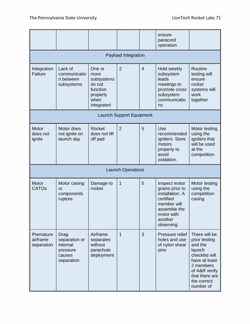
The Pennsylvania State University LionTech Rocket Labs 71
ensure paracord operation
Payload Integration
Integration Failure
Lack of communication between subsystems
One or more subsystems do not function properly when integrated
2 4 Hold weekly subsystem leads meetings to promote cross subsystem communications
Routine testing will ensure rocket systems will work together
Launch Support Equipment
Motor does not ignite
Motor does not ignite on launch day
Rocket does not lift off pad
2 5 Use recommended igniters. Store motors properly to avoid oxidation.
Motor testing using the igniters that will be used at the competition
Launch Operations
Motor CATOs
Motor casing or components rupture
Damage to rocket
1 5 Inspect motor grains prior to installation. A certified member will assemble the motor with another observing.
Motor testing using the competition casing
Premature airframe separation
Drag separation or internal pressure causes separation
Airframe separates without parachute deployment
1 3 Pressure relief holes and use of nylon shear pins
There will be prior testing and the launch checklist will have at least 2 members of A&R verify that there are the correct number of

The Pennsylvania State University LionTech Rocket Labs 72
shear pins and grams of black powder in the blast caps
Drogue chute fails to deploy
Drogue chute either does not leave the tube or doesn’t unravel
Kinetic energy at main chute deployment is higher than expected
2 3 Ground test recovery system for optimal ejection strength
The launch checklist will have two members of A&R ensure that the parachute is packed correctly and there is sufficient black powder in the blast caps for the parachute to deploy.
Main chute fails to deploy
Main chute either does not leave tube or doesn’t unravel
Kinetic energy of rocket at ground impact is too high
2 4 Maintain sufficient airflow to deploy main chute from deployment bag
The launch checklist will have two members of A&R ensure that the parachute is packed correctly and there is sufficient black powder in the blast caps for the parachute to deploy.
Main chute
Main chute deploys at apogee
Kinetic energy during
3 3 Proper labeling of wires, ground
Two members of A&R will

The Pennsylvania State University LionTech Rocket Labs 73
deploys first
main chute deployment is too high
test, use correct number of shear pins
verify that the parachutes are in the correct segment of the rocket and that all of the wires are going to the correct charges and altimeters.
Main and drogue get tangled together
Main chute gets deployed below drogue and tangles
Rocket descent is unstable, kinetic energy at ground impact is too high
2 4 Use adequate lengths of recovery harness
There will be prior test launches where the length of the shock cord will be confirmed to work. The shock cords will be at least 10 ft different in length.
Ejection charges do not ignite
No parachute deployment
Ballistic descent, ground impact kinetic energy is too high
2 5 Use fresh batteries for each launch, check altimeter continuity
Two members of A&R will confirm that the charges are loaded correctly, the batteries are new, and the altimeter has continuity beeps
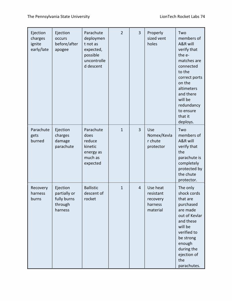
The Pennsylvania State University LionTech Rocket Labs 74
Ejection charges ignite early/late
Ejection occurs before/after apogee
Parachute deployment not as expected, possible uncontrolled descent
2 3 Properly sized vent holes
Two members of A&R will verify that the e-matches are connected to the correct ports on the altimeters and there will be redundancy to ensure that it deploys.
Parachute gets burned
Ejection charges damage parachute
Parachute does reduce kinetic energy as much as expected
1 3 Use Nomex/Kevlar chute protector
Two members of A&R will verify that the parachute is completely protected by the chute protector.
Recovery harness burns
Ejection partially or fully burns through harness
Ballistic descent of rocket
1 4 Use heat resistant recovery harness material
The only shock cords that are purchased are made out of Kevlar and these will be verified to be strong enough during the ejection of the parachutes.

The Pennsylvania State University LionTech Rocket Labs 75
Recovery harness attachment breaks
Bulkhead, U-bolt or harness breaks
Uncontrolled rocket descent
2 3 Adequately size recovery harness, flight test
There will be modeling done before any launches and there will be test launches that will confirm that the bulkheads and U-bolts are strong enough
High kinetic energy at landing
Parachutes undersized, or intentionally deployed at incorrect altitude
Rocket lands at an excessive velocity
2 4 Accurate estimate, OpenRocket
There will be modelling to confirm that the parachutes will be the correct size and A&R will receive confirmation from NASA about the parachutes chosen
Altimeter doesn’t detect pressure change
Altimeter is unable to detect pressure change during ascent
No data is recorded and ejection charges are not fired, ballistic descent of rocket
1 5 Properly sized vent holes away from airflow obstructions
The vent hole size will be checked several times in practice launches and the hole will be of adequate size compared to previous similar

The Pennsylvania State University LionTech Rocket Labs 76
rockets that we have successfully launched.
Loss of power
Battery dies or wires become unattached
Altimeter does not record data, ejection charges are not fires, rocket descends ballistically
2 4 Use fresh batteries that can withstand rocket accelerations, redundant altimeters
New batteries will be used on launch day and two A&R members will confirm that the batteries are connected and wired securely.
Parachute gets tangled
Parachute is not packed correctly
Lowered coefficient of drag, kinetic energy of the rocket would be above target levels
2 3 Pack parachute correctly and have it confirmed by at least two other A&R members
Two members of A&R will confirm that the parachutes are packed correctly.
Ejection charges are not sufficient
Rocket fails to deploy one or both of the parachutes
Higher kinetic energy when landing, potentially ballistic descent
1 4 Do ground testing to ensure that the ejection charges will separate the rocket
The ground tests and previous launches will confirm the proper amount of black powder to use and two members of A&R will confirm that the charges

The Pennsylvania State University LionTech Rocket Labs 77
are packed correctly
Environmental Concerns
One of the main environmental concerns includes the disposal of toxic substances, due to use
of such substances in rocket construction. All toxic substances will be disposed in accordance
with local laws and regulations by Penn State Environmental Health and Safety (EHS). During a
launch, measures will be taken to minimize changes to the local environment due to the
emission of hot, toxic gases from the rocket motor during launch. A safe radius around the pad
will be cleared of combustible materials. High winds during rocket flight could adversely impact
the landing guidance system. Table 14 below summarizes this risks, ranking the likelihood and
impact on a scale of 1-5.
Table 14: Environmental Hazards
Environmental Hazard
Cause Effect Likelihood Impact Mitigation Verification
Solvent, paint or other toxic substance released to environment
Improper disposal of used chemicals
Potential contamination of environment
2 3 Contact relevant personnel in building
Penn State EHS is contacted and notified
Motor gases Hot, toxic gases released during takeoff
Contamination of environment, air pollution hazard
4 2 Follow all launch safety regulations
Checklist for safety regulation to be completed prior to launch
High winds (>10 mph) during recovery
High wind makes operation of recovery helicopter system difficult
Rocket section is driven off course and lands in hazardous location
3 4 Emergency parachute to safely land rocket, launch in low wind conditions
Visual verification, wind speed monitor
Motor burning into ground
Titanium sponges, motor burning out without
Cause fire at launch pad or surrounding area
1 4 Not using motors with titanium sponges, securely retaining
Ensure that “Skidmark” and similar motors are not used, test motor

The Pennsylvania State University LionTech Rocket Labs 78
launching the vehicle
the motor into the booster
retention system
Ejection charge fails to go off during launch
Altimeter failure
Charge could go off on ground and cause a fire
1 5 Redundant altimeters
Follow standard launch procedure checklist
Parachutes exposed to ejection charges
Nomex Chute Protector doesn’t fully cover the parachutes
Parachutes catch on fire which could spread if still lit when vehicle lands
1 5 Properly cover parachutes with Nomex cover
Follow launch procedure checklist
FOPS leaks fluid outside the rocket body
Physical damage to FOPS fluid containment or transfer section
Chemical damage occurs to local area/watershed
3 2 Organic materials (cornstarch) will be used for dilatant
Test flights will ensure the ability of external FOPS components to survive landing
Kiwi rotor or propeller spins after landing
Programming error
Damage to local flora
2 1 Test Kiwi before initial launch
Examine robustness of programming
Overall Project Risk Management There are several concerns with the overall project, mostly related to budget and personnel
management. These are presented in Table 15 below.
Table 15: Overall Project Risks
Risk Cause Effect Likelihood Impact Mitigation
Labor leaves/graduates
Seniors graduate or students stop attending meetings
There are no longer enough students available to perform the necessary work
High Medium Recruitment at beginning of each semester. Team building activities.

The Pennsylvania State University LionTech Rocket Labs 79
Club loses funding
One or more sources can no longer provide funding
There is not enough money to pay for transportation or necessary parts/equipment
Low High Dedicated member to track expenses and make funding contracts possible.
Project falls behind schedule
Team fails to build critical components in a timely manner
Major milestones are not met in time
Medium Medium Weekly status meetings, follow project plan
Failure to acquire transportation
Transportation to Alabama not acquire
Team is unable to travel to the competition
Low High Have plan to carpool if necessary
Injury of team personnel
Hazards outlined in
Table 13
Team member is injured
Low High Inform and enforce team safety
Project over budget
Testing/fabrication/ travel costs exceed expectations
Project cost exceeds amount of money projected.
Low Medium Compare prices from different vendors, avoid excess shipping costs
Damage during testing
Accident/malfunction during testing
Catastrophic damage to rocket
Medium Medium Ground testing, maintain stock of spare parts
Club loses facilities
University revokes club access to lab
Club loses access to 46 Hammond
Low High Maintain clean environment and proper storage of materials
Parts are unavailable
Parts needed for rocket are not available commercially
Rocket cannot be completed using planned parts
Low Medium Use non - exotic

The Pennsylvania State University LionTech Rocket Labs 80
materials and check for availability. Order parts far in advance
Theft of equipment
Parts or testing equipment gets stolen
Rocket construction becomes more difficult, excess cost to the club
Low Medium Only subsystem leaders and officers will have card access to the LTRL lab

The Pennsylvania State University LionTech Rocket Labs 81
Section 6: Payload Criteria

The Pennsylvania State University LionTech Rocket Labs 82
1: Selection, Design and Rationale of payload FOPS: Due to the inadequate performance of the prototype system in the subscale launch, a new
method of inserting the specimen before the liquid was developed. The shear thickening liquid
remains the main method of protection; however, the open-cell foam which was featured in
the original design was removed, eliminating much of the gross acceleration isolation. A spring
system is used to fulfill the purpose of the open-cell foam. This design retains the force-
distribution abilities of the dilatant while employing the spring system’s acceleration isolation
abilities. The drawing for FOPS is contained in Figure 25 below.
Figure 25: FOPS Drawing
The exterior of FOPS is integrated into the body of the rocket, and is attached to the materials
bag (shown in black) by elastic bands or springs. These bands allow the bag to be isolated from
the shocks and forces of launch and recovery, while still restraining the motion of the bag. The
dilatant will fill the space between the materials bag and the exterior of the bay. It will be held
in a reservoir (shown in black above the FOPS bay) until after the fragile object is placed into
the materials bag. Once the object is secure, the FOPS bay valve will be opened manually from
the exterior, and the non-Newtonian fluid will flow into the bay. FOPS dimensions are shown in
Figure 26.

The Pennsylvania State University LionTech Rocket Labs 83
Figure 26: FOPS Dimensions
As evident by the drawing dimensions, the materials bag is large enough to contain the
unknown fragile object(s) of dimensions 3.5 x 6 inches. FOPS will act as a section of rocket body,
and be independent of other systems, as it does not require power or actuation and is
completely contained within the FOPS bay. The max acceleration for the rocket is 8 G’s, and this
system is designed to handle this acceleration.
Kiwi: Originally, Kiwi was designed as a coaxial helicopter. After further research into the nature of
coaxial rotor mechanisms, the design was changed to an autogiro, or gyrocopter, which uses a
large, unpowered rotor on the top of the craft to provide lift. The drag of forward motion on
the rotor is greater on the leading edge than the trailing edge, which exerts a moment that
turns the rotor and generates downward thrust. A small powered propeller on the rear of the
craft provides forward thrust. Simpler mechanical systems and increased stability make the
autogiro preferable to the coaxial helicopter as a small-scale autonomous vehicle for use in this
competition. Figure 27 shows the full body view of Kiwi.

The Pennsylvania State University LionTech Rocket Labs 84
Figure 27: Exterior View of Kiwi Vehicle
Kiwi will be powered by a front propeller and steered by a rear rudder, both shown in the
above figure. The top rotor will provide lift to slow the descent of the vehicle. Kiwi weighs 17
oz, and its terminal velocity will cause Kiwi to be below the kinetic energy requirements even if
it falls without parachutes. The Kiwi dimensions are shown in Figure 28 below.
Figure 28: Kiwi vehicle dimensions
The size of the front propeller is 3 inches due to space constraints. Using equations 4-6 below,
the forward velocity was determined:

The Pennsylvania State University LionTech Rocket Labs 85
𝑉𝑡𝑖𝑝 = 𝜔𝑟 (4)
𝑇 =1
2𝜌𝐴𝑉𝑡𝑖𝑝
2𝐶𝑙𝑎𝑣𝑔(5)
𝑉𝑓 = 𝑉𝑓𝑛𝑑√𝑇
2𝜌𝐴(6)
The ideal forward velocity was found to be 94 ft/s, however, this number does not account for
drag or the downwash of the top rotor. The top rotor will provide lift, and be 1-foot-long due to
size constraints set by the Kiwi Bay. A view of Kiwi’s interior is shown in Figure 29 below.
Figure 29: Cross Section view of Kiwi Vehicle
The white cylinder at the bottom front of the vehicle contains the parachute, which will be used
for landing and in case of emergencies. The shelves shown in the interior of the vehicle will be
used to hold the electrical components in place. The electrical schematic is shown later in the
report. The fasteners used to hold the electronics are shown in Figure 30 below.

The Pennsylvania State University LionTech Rocket Labs 86
Figure 30: Fastening mechanism for the electronic components
The shelves will be equipped with loops (shown in blue) so that the electrical components can
be secured to the shelves via zip ties (shown in gray). Securing the components in this way will
allow for easy adjustment of the components and a reduction of weight.
Kiwi will be encased in a shell within the rocket body. This shell acts to restrain Kiwi during the
ascent of the rocket, protecting it from impact against the walls of the rocket. When the rocket
reaches apogee and the body opens, the shell’s two sections separate, and allow Kiwi to exit
the rocket body and begin descending. After its exit, Kiwi acts independently from the rocket.
Below are the electrical schematics used in the Kiwi system. The schematic for the ground
station for the Kiwi system is shown in Figure 31.
Figure 31: Ground station wiring schematic

The Pennsylvania State University LionTech Rocket Labs 87
The ground station contains a laptop, a Leonardo Arduino, and an Xbee radio. The Laptop is
used for interfacing with and powering an Arduino. The Arduino is equipped with an Xbee
which allows the team and Kiwi to communicate. The team will use the Xbee to send messages
to Kiwi to ensure that the communication link has not been lost. If the link is lost, the Kiwi flight
computer will deploy the parachute and power off all systems. Additionally, the Ground Station
Arduino is equipped with an Emergency PWR off button. Pressing this button will transmit a
message to the Kiwi flight computer that will deploy the parachute and shut down all systems.
The schematic for the electrical systems on board the Kiwi vehicle are is shown in Figure 32.
Figure 32: Schematic for the electrical systems onboard the gyrocopter
A Mini Pro Arduino will act as the flight computer on board Kiwi. It will receive data from the
GPS and IMU to determine Kiwi’s location, speed, and direction of movement. The Mini Pro will
have an indicator LED which will be visible from the outside of the vehicle to show that the
system is receiving power. The flight computer will be powered by a Lipo Battery through a
voltage regulator. The system will be activated by flipping an exterior switch which will connect
the battery to the voltage regulator. An additional Lipo battery will power the motor that drives
the propeller. The battery will also have an external switch to connect it to the voltage
regulator. The motor will be connected to an electronic speed controller, which will receive
signals from the Arduino. A servo will control the rudder, as directed by the Arduino to adjust
the direction of the vehicle’s flight. The Arduino will use an Xbee radio to communicate with the
ground station. The phototransistor will be used to determine when Kiwi has exited the rocket.

The Pennsylvania State University LionTech Rocket Labs 88
The flight computer will also be equipped with an e-match to eject the parachute. There will
also be a completely separate altimeter system, including batteries, an altimeter, and an e-
match, on board Kiwi, for redundancy. This altimeter will automatically trigger an e-match at
150 feet to ensure the safe recovery of the Kiwi. Figure 33 shows the software flow diagram of
the Ground Station.
Figure 33: Kiwi Ground Station (GS) Software Diagram
The ground station is mainly used for monitoring Kiwi’s stability and flight path and to provide a
way to remotely shutdown the vehicle and deploy the parachutes. The system begins by
sending the communication check signal to the vehicle. It then checks if the emergency button
has been pressed. If it has, the ground station will send a shutdown message to Kiwi, which will
initiate a shutdown sequence on the vehicle. If the emergency button has not been pressed,
the laptop will display the received location and velocity data from Kiwi so the team can
monitor the flight of the vehicle. The Kiwi on board software flow diagram is shown in Figure
34.
As shown in the diagram, the flight computer will not power the propellers unless the ground
station signal has been received, the altitude is over 100 feet, the target coordinates have been
received, and a photoelectric sensor reports that Kiwi is outside the rocket. Once all of these
criteria have been met, the autogiro will wait thirty seconds and then activate the propellers.
After verifying that Kiwi is still in communication with the ground station, a shutdown signal has
not been received, and that the altitude is greater than 150 feet, the flight computer will check
that the vehicle is on the correct trajectory. If the trajectory is correct, the Xbee will send the
GPS coordinates and the velocity of the vehicle so the team can ensure the flight is stable. If the
trajectory is not correct, the proper adjustments will be made and then the Location and
velocity data will be sent to the team. If the communication check signal has not been received
in a specific number of iterations, a shutdown signal has been received, or the altitude of Kiwi is
less than 150 ft, the flight computer will deploy the parachute by activating the e-match, and
turn off all systems.

The Pennsylvania State University LionTech Rocket Labs 89
Figure 34: Kiwi’s onboard software flow diagram

The Pennsylvania State University LionTech Rocket Labs 90
Section 7: Project Plan

The Pennsylvania State University LionTech Rocket Labs 91
1: Testing Airframe Material Testing: Material testing is to be completed alongside full-scale construction which will help verify that
the launch vehicle is capable of withstanding the expected loads from launch through to
touchdown. Lab facilities at Research Building West at Penn State will be used for the testing to
create an apparatus which requires the machining of aluminum bulk plates in order to hold the
test specimen to the tensile test machine. Previously, a similar tensile test had been conducted
on a G12 fiberglass airframe specimen as seen in Figure 35 and Figure 36.
The greatest failure mode for the airframe is in tension where screws are used to hold them
together. During testing, aluminum bulk plates were attached to the 3-inch diameter G12
fiberglass tube using four and six screws on each respective bulk plate. The whole specimen
was then attached to the tensile test machine using two aluminum rods 0.77 inches in
diameter, as seen in Figure 35.
Figure 35: Tensile Test Setup for G12 Fiberglass Specimen

The Pennsylvania State University LionTech Rocket Labs 92
Figure 36: Force vs. Displacement of 3-inch diameter G12 Fiberglass Specimen
The tensile test machine continuously applied axial load until specimen failure. Data obtained
from the tensile testing machine resulted in a yield force of approximately 3,780 pounds, as
noted in Figure 36.
This yield force resulted in a corresponding yield stress of approximately 42.7 ksi, as calculated
in Figure 37. This is due to the fact that the failure of the specimen occurred on the side of the
fiberglass that had 4 screws, increasing the stress at those points.

The Pennsylvania State University LionTech Rocket Labs 93
Figure 37: Calculation of Yield Stress from Tensile Test Data
This test methodology is slotted to be performed on a specimen of Blue Tube 2.0 airframe by
February 11th, 2017. Preparations have been made for reserving lab space and the equipment
necessary for carrying out the test. The necessary bulk plates will be constructed during the
coming days and will consist of machined 6061 Aluminum bar stock. After the creation of the
bulk plates, testing will be able to commence in relatively short order, and data will be analyzed
for comparison of Blue Tube 2.0 Against The existing data from the G12 Fiberglass specimen
mentioned above.
Payload Testing Table 16: Payload Test Overview
Test (7.1.1)
Objective (7.1.2)
Success Criteria (7.1.2)
Variable (7.1.2)
Methodology (7.1.2)
Completed?
(Y/N)
FOPS: Impact test.
To determine if the dilatant will be able to protect the object
The fragile object does not break.
The height at which the system is dropped
FOPS is dropped from increasing height.
Y
FOPS: Optimal Concentration Determination
Determine which concentration is the most effective at reducing forces on the fragile object
The least amount of stress compared to the other concentrations is measured by the force sensor
The concentration of the fluid
Force sensors are placed in different concentrations of the non-Newtonian Fluid and dropped from
N

The Pennsylvania State University LionTech Rocket Labs 94
the same height.
Kiwi: Stability Test
Determine if the orientation of Kiwi will affect its ability to stabilize itself
Kiwi is able to correctly orient itself at all different starting attitudes
The beginning orientation of Kiwi
Kiwi is dropped from a set height at different orientations
N
Kiwi: Parachute Test
To determine if the parachute can safely slow the descent of Kiwi regardless of orientation
The parachute fully opens during descent regardless of orientation
The beginning orientation of Kiwi
Kiwi’s parachute is activated at different orientations
N
Kiwi: Remote Turn off Distance Test
To determine the height at which Kiwi’s parachute can be activated and the vehicle can be powered off in case of emergencies
Kiwi is powered off and the parachute is successfully deployed
The height at which the team attempts to power off Kiwi
The emergency power off button is activated midway through Kiwi’s descent off of a parking deck
N
At this point in time, the team has only completed the first test in Table 16 for FOPS. The test
procedure was to drop a cylindrical container filled with the dilatant and the fragile object (an
egg) off of increasing levels of a parking deck. This test was a success, as the system protected
the fragile object from any damage during each test run. This test served as proof of concept,
and allowed LTRL to move forward with designing a system which would use the dilatant as its
main source of protection.
Drag coefficient testing Two experimental methods will be used to compensate for the high drag estimation in
OpenRocket. One, through multiple full scale test launches it will be experimentally determined
how much the actual apogee differs from simulations. If enough launches are performed than

The Pennsylvania State University LionTech Rocket Labs 95
compensation for factors such a wind should be possible. If not, then this method will not be as
effective but it will still prove useful in predicting apogee in the specific winds pertaining to
each launch.
Two, by implementing wind tunnel testing on the subscale rocket. By taking drag force readings
at varying wind speeds in the controlled tunnel environment, a drag coefficient profile can be
developed as a function of rocket velocity. Due to limitations of the tunnel, the velocity will
range from zero to approximately 120 ft/s. Now, although this velocity range is much lower
than the maximum predicted rocket velocity, because the prediction does not exceed Mach
0.61, incompressibility will be assumed. Due to said assumption extrapolation is possible
between the low speed tests and the much higher flight speeds. This testing has not yet
occurred but will be performed in the Penn State Aerospace Department’s Boundary Layer
Tunnel in the coming months. Figure 38 is a schematic (not to scale) of the test setup.
Figure 38: Diagram of Wind Tunnel Test Setup
Static Motor testing: To further validate the flight predictions, section 3.4.1, the motor characteristics mentioned in
section 3.1.2 are experimentally validated. This will be done under the supervision of trained
and experienced researchers. During the testing characteristics such as burn time, peak thrust,
average thrust, impulse, and the overall shape of the thrust curve will be determined for each
tested motor and then compared to the specifications given by the manufacturer. This will
ensure that the predictions based on the manufacturer specifications will not have error

The Pennsylvania State University LionTech Rocket Labs 96
resulting from incorrect motor characteristics. The testing will use three L1350 motors in order
for a standard deviation to be calculated for the various motor characteristics mentioned
above. The standard deviation will also be used to verify consistency between motors and the
given specifications. Figure 39 shows the motor testing setup. The I-Beam not shown in the
figure is used to secure the entire assembly to ground during the static test firings. During
which time all data will be collected via the 500 lb. load cell from within a concrete bunker.
Static motor testing has not yet occurred, but is planned for the coming weeks.
Figure 39: Static Motor Test Setup

The Pennsylvania State University LionTech Rocket Labs 97
2: Requirements Compliance
Requirement Verification Table 17: Vehicle Requirements
Requirement Number
Method of Verification
Verification
1.1 Demonstration The onboard payload will be delivered to an apogee of 5,280 feet above ground level in a test launch.
1.2 Inspection The vehicle shall carry two StratoLogger CF barometric altimeters, which are commercially available, for recording the official altitude.
1.2.1 Inspection The official altitude shall be reported via a series of beeps from the official scoring altimeter post launch.
1.2.2 Inspection The vehicle will have a second altimeter to provide dual redundancy for all deployment charges.
1.2.3 Inspection At the LRR, a NASA official will mark the altimeter that will be used for the official scoring.
1.2.4 Inspection At the launch field, a NASA official will obtain the altitude by listening to the audible beeps reported by the official competition, marked altimeter.
1.2.5 Inspection All audible electronics, other than the official scoring altimeter shall be capable of turning off.
1.2.6.1-4 Inspection All competition scoring rules as listed in the handbook are understood and shall be followed.
1.3 Inspection All recovery electronics shall be powered by commercially available 9V batteries.
1.4 Demonstration Materials and construction methods used by the club allow for the repeated use of the vehicle. Demonstrated by the multiple launches required by the test vehicle.
1.5 Demonstration Flight vehicle’s design consist of three sections to contain the parts for payload, avionics and recovery, and propulsion respectively as seen by the separation points during launch.
1.6 Inspection The vehicle contains a single stage three grain motor.

The Pennsylvania State University LionTech Rocket Labs 98
1.7 Demonstration Vehicle is easily assembled and disassembled by using screws and couplers to fit each section together.
1.8 Demonstration The launch vehicle shall be capable of being prepared for launch in a period of 4 hours. And capable of remaining in launch-ready configuration at the pad for a minimum of 1 hour without losing the functionality of any critical on-board component.
1.9 Testing The launch vehicle shall be capable of being launched by a standard 12-volt direct current firing system. Engine firing will be tested by propulsion prior to first flight.
1.10 Demonstration The launch vehicle shall require no external circuitry or special ground support equipment to initiate launch. Demonstrated through launch of subscale.
1.11 Inspection The launch vehicle shall use a commercially available solid motor propulsion system using ammonium perchlorate composite propellant (APCP) which is approved and certified by the National Association of Rocketry (NAR), Tripoli Rocketry Association (TRA), and/or the Canadian Association of Rocketry (CAR).
1.11.1 Testing (As of PDR the selected motor is the L1350) Final motor choices shall be made by the Critical Design Review
1.11.2 Inspection In the event the motor needs to be changed after CDR it shall be approved by the NASA Range Safety Officer (RSO)
1.12.1 Analysis The minimum factor of safety shall be 4:1 with supporting design documentation included in all milestone reviews.
1.12.2 Analysis The low-cycle fatigue life shall be a minimum of 4:1.
1.12.3 N/A Each pressure vessel shall include a solenoid pressure relief valve that sees the full pressure of the tank. Our design does not contain any pressure vessels.
1.12.4 N/A Full pedigree of the tank shall be described, including the application for which the tank was designed, and the history of the tank, including the number of pressure cycles put on the tank, by

The Pennsylvania State University LionTech Rocket Labs 99
whom, and when. Our design does not contain any pressure vessels.
1.13 Testing/Analysis Current selection is rated at an impulse of 4280 Ns (67% of the maximum L class motor 5120 Ns allowed for use in university competition)
1.14 Simulation The stability margin at point of static exit currently sits at 2.25 calibers, exceeding the 2.0 required stability margin. These stability margins were simulated using OpenRocket.
1.15 Simulation The vehicle will have a minimum velocity of 76.6 ft/s at rail exit. (Min allowable is 52 ft/s)
1.16 N/A A subscale launch for the vehicle is currently scheduled for November 13th, 2016.
1.16.1 Simulation/Inspection Subscale design will resemble a 1:2 scale of the full size launch vehicle as shown in our OpenRocket models.
1.16.2 Inspection The subscale shall carry an altimeter for apogee altitude reporting.
1.17 N/A A checklist shall be made to ensure that the sub-requirements of 1.17 shall all be followed
1.18 Inspection No structural protuberance will be located forward of the burnout center of gravity.
1.19.1 Inspection The vehicle will not include forward canards.
1.19.2 Inspection The launch vehicle shall not utilize forward firing motors.
1.19.3 Inspection The launch vehicle shall not utilize motors that expel titanium sponges.
1.19.4 Inspection The launch vehicle shall not utilize hybrid motors.
1.19.5 Inspection The launch vehicle shall not utilize a cluster of motors.
1.19.6 Analysis The launch vehicle shall not utilize friction fitting for motors, instead utilizing a tail cone for motor retention
1.19.7 Analysis The launch vehicle will reach approximately Mach 0.6, below the Mach 1 maximum requirement. This

The Pennsylvania State University LionTech Rocket Labs 100
value was simulated using OpenRocket. Value will also be verified after test launches.
1.19.8 Simulation The vehicle ballast will not exceed 10% of vehicle weight. The current simulation includes a 10% ballast.

The Pennsylvania State University LionTech Rocket Labs 101
Table 18: Recovery System Requirements
Requirement Number
Method of Verification
Verification
2.1 Demonstration A drogue will deploy at apogee and a main will deploy at 700ft. Demonstrated through full scale test launch.
2.2 Demonstration LTRL will ground test ejection charges before any subscale or full scale launch. There will be ground tests before any initial launches.
2.3 Analysis The parachutes will be correctly sized so that each component of the rocket lands within the kinetic energy constraint of 75ft-lbs. The current parachute selection has the rocket well under the kinetic energy limit.
2.4 Inspection The recovery system wiring will be completely independent of any payload components.
2.5 Inspection There will be two independent altimeters, power supplies, and ejection charges for dual redundancy.
2.6 Demonstration Motor ejection will not be used to separate the rocket. The altimeter will control the ejection charges.
2.7 Inspection Each altimeter will have a separate key switch that will be accessible from the outside of the rocket in order to arm each altimeter independently.
2.8 Inspection Each altimeter will have an independent battery.
2.9 Demonstration Each key switch will be able to stay in the on position while on the launch pad.
2.10 Demonstration Removable sheer pins will be used to keep the rocket together for both parachute compartments until the ejection charges cause separation.
2.11 N/A There will be a GPS unit installed that will constantly send the position of the rocket.
2.11.1 Inspection All sections of the rocket will be tethered together, but if any are not, they will have independent GPS units. Specifically KIWI will fall independent with a second GPS unit.
2.11.2 Inspection The GPS unit will be functional on launch day. There will be a spare GPS unit in case of any electronic failures before the launch.
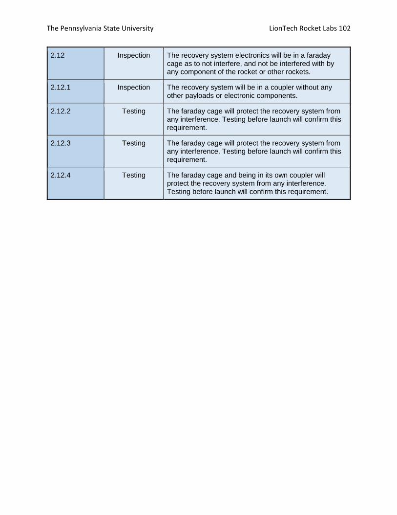
The Pennsylvania State University LionTech Rocket Labs 102
2.12 Inspection The recovery system electronics will be in a faraday cage as to not interfere, and not be interfered with by any component of the rocket or other rockets.
2.12.1 Inspection The recovery system will be in a coupler without any other payloads or electronic components.
2.12.2 Testing The faraday cage will protect the recovery system from any interference. Testing before launch will confirm this requirement.
2.12.3 Testing The faraday cage will protect the recovery system from any interference. Testing before launch will confirm this requirement.
2.12.4 Testing The faraday cage and being in its own coupler will protect the recovery system from any interference. Testing before launch will confirm this requirement.

The Pennsylvania State University LionTech Rocket Labs 103
Table 19: Experimental Requirements
Requirement Number
Method of Verification
Verification
3.1.1 Inspection The rocket will carry a fragile specimen protection experiment as a payload.
3.1.2 Demonstration At the launch, an additional autonomous autogyro payload will be flown in the rocket, but will not be submitted for scoring.
3.1.3 Inspection The autogyro payload will be included in reports so that the safety of the project can be reviewed by overseeing engineers.
3.1.3 Inspection The autogyro payload will be equipped with its own GPS.
3.1.3 Analysis The autogyro payload will be equipped with an emergency parachute system to ensure that it comes down in accordance with the kinetic energy requirements.
3.4.1 Demonstration/ Analysis
A chamber filled with dilatant will house a flexible bag, which will contain and protect the fragile materials. The chamber will be suspended by elastic bands in order to provide gross acceleration dissipation.
3.4.1.1 Demonstration All specimens will be placed in separate bags and inserted into the dilatant, which will cushion each specimen individually.
3.4.1.2 Analysis The cushioning provided by the dilatant, combined with the acceleration dissipation of the elastic bands will ensure that any material placed inside the chamber will be able to survive the accelerations and shocks of launch, landing, and recovery.
3.4.1.3 Inspection A sealable materials bag inside the chamber will allow for insertion of specimens, while the dilatant will allow for objects to be of unknown size and shape.
3.4.1.4 Testing/Inspection All dilatant for cushioning will be permanently housed inside the rocket during preparation, with enough volume left inside the bay between the elastic regions and materials chamber to permit for displacement due to specimen volume. All specimens will be sealed in watertight bags.
3.4.1.5 Inspection The material chamber will be large enough to house a 3.5” by 6” cylinder.

The Pennsylvania State University LionTech Rocket Labs 104
3.4.1.6 Analysis The mass of the objects will be accounted for in the estimations of flight, as well as the accelerative forces on the materials chamber.
Table 20: Safety Requirements
Requirement Number
Method of Verification
Verification
4.1 Demonstration The team will use launch and safety checklists. The team will demonstrate the use of launch and safety checklists during all launches.
4.2 N/A Laura Reese is listed as safety officer
4.3 N/A The safety officer will perform all responsibilities as listed.
4.3.1 Inspection The safety officer will monitor the team with an emphasis on safety.
4.3.1.1 Inspection The safety officer will monitor the team during design of the vehicle and launcher.
4.3.1.2 Inspection The safety officer will monitor the team during construction of the vehicle and launcher.
4.3.1.3 Inspection The safety officer will monitor the team during assembly of the vehicle and launcher.
4.3.1.4 Inspection The safety officer will monitor the team during ground testing of the vehicle and launcher.
4.3.1.5 Inspection The safety officer will monitor the team with an emphasis on safety during the subscale launch tests.
4.3.1.6 Inspection The safety officer will monitor the team with an emphasis on safety during the full-scale launch test.
4.3.1.7 Inspection The safety officer will monitor the team with an emphasis on safety during the launch day.

The Pennsylvania State University LionTech Rocket Labs 105
4.3.1.8 Inspection The safety officer will monitor the team with an emphasis on safety during the recovery activities.
4.3.1.9 Inspection The safety officer will monitor the team with an emphasis on safety during educational activities.
4.3.2 N/A The safety officer will implement all procedures developed by the team for construction, assembly, launch and recovery activities.
4.3.3 N/A The safety officer will manage and maintain current versions of the team’s hazard analyses, failure modes analyses, procedures and chemical inventory data.
4.3.4 N/A The safety officer will assist in the writing and development of the team’s hazard analyses, failure modes analyses and procedures.
4.4 N/A The team’s mentor is Alex Balcher
4.5 N/A The team will abide by the rules and guidance of the RSO.
4.6 N/A The team will abide by all rules set forth by the FAA.

The Pennsylvania State University LionTech Rocket Labs 106
Table 21: General Requirements
Requirement Number
Method of Verification
Verification
5.1 Demonstration Students on the team will do 100% of the project, including design, construction, written reports, presentations, and flight preparation with the exception of assembling the motors and handling black powder or any variant of ejection charges, or preparing and installing electric matches.
5.2 Demonstration The team provided a project plan including project milestones, budget and community support, checklists, personnel assigned, educational engagement events, risks, and mitigations. The team will follow the project plan.
5.3 N/A Foreign National Team members will be identified to NASA by Preliminary Design Review.
5.4 Demonstration The team members attending the launch will be identified by Critical Design Review.
5.4.1 N/A Only actively engaged team members will come to launch week activities.
5.4.2 N/A One mentor will come to launch week activities.
5.4.3 N/A At most two adult educators will come to launch week activities.
5.5 Demonstration The team will engage at least 200 participants in educational, hands-on science and math related activities throughout the year and write reports on these events. The reports will be submitted at most two weeks after the activity.
5.6 Inspection The team has developed a website for the competition. The website will be kept up to date throughout the competition.
5.7 Demonstration Teams will post, and make available for download, the required deliverables to the team website by the due dates specified in the project timeline.
5.8 Demonstration All reports shall be delivered in pdf format.

The Pennsylvania State University LionTech Rocket Labs 107
5.9 Demonstration Every report shall include a table of contents outlining major sections and their respective sub-sections.
5.10 Demonstration Every report shall include page numbers at the bottom of the page.
5.11 Demonstration The team shall provide proper video conference equipment needed to perform a video teleconference with the review board.
5.12 Demonstration The flight vehicle will be capable of launching using the launch pads provided by the launch service provider.
5.13 Demonstration The team will meet the Architectural and Transportation Barriers Compliance Board Electronic and Information Technology (EIT) Accessibility Standards.

The Pennsylvania State University LionTech Rocket Labs 108
Team Derived Requirements Each subsystem, as well as the safety officer, derived project specific requirements as listed
below. These are an extension beyond the general requirements given and will be used by the
club to target specific aspects of the project.
Table 22: Derived Requirements
1 Payload
1.1 Fragile material is recovered from the bay is the same condition as received.
Testing Test the materials protection system with various fragile objects vulnerable to bending, breakage, collapse, and liquid damage
1.2 No materials will leave the materials bay until recovery
Inspection Perform pre-flight check on rocket and during material bay loading
1.3 The protection payload does not cause the vehicle to become unstable.
Inspection/Analysis Observe the vehicle’s flight during subscale and full-scale test launches.
1.4 Kiwi becomes stable upon exit of the rocket.
Inspection/Analysis Observe Kiwi’s flight during subscale and full-scale test launches.
1.5 Kiwi lands within 5 feet of the landing point.
Testing Measure the distance between Kiwi’s actual landing site and Kiwi’s attempted landing site.
1.6 All parts of the fragile object protection system and Kiwi remain intact and fully functional during the duration of the rocket flight.
Testing Include the protection system in subscale and full-scale test launches to test how the parts of the system withstand forces placed on them by the vehicle’s flight.
1.7 All FOPS and Kiwi systems can be used in another flight.
Inspection/Analysis Determine if the systems are structurally sound enough to be flown again
2 Avionics and Recovery
2.1 The redundant altimeter will be at a delay
Demonstration The redundant altimeter will be at a slight delay.

The Pennsylvania State University LionTech Rocket Labs 109
as to not overwhelm the body tube.
2.2 There will be backup electronics in case of failure on launch day.
Demonstration The team will have backup altimeters and GPS units in case of failure before launch.
2.3 Pressure port will be adequately sized.
Testing There will be ground testing and test launches to ensure that the pressure port is a proper size.
2.4 Structural materials will be strong enough to maintain integrity throughout descent and landing.
Testing There will be estimations and testing done to ensure the integrity of the structure throughout parachute ejections and landing.
2.4.1 Avionics board will remain structurally sound throughout launch, descent, and landing.
Testing The PLA avionics board will be tested prior to launch in high stress and high heat conditions.
2.4.2 3D printed AV Bay cover will be secured to the body tube coupler in such that the avionics bay as a whole will remain secured.
Testing/Demonstration The avionics bay cover/coupler will be secured with a high factor of safety through the use of both epoxy and steel screws.
2.5 All electrical connections will be tightly secured throughout launch.
Inspection On launch day all electrical connections between the altimeters, batteries, and e-matches will be double checked.
2.5.1 Battery terminal connections will remain tight throughout the launch.
Inspection Design iterations of avionics bay moved batteries to a horizontal position within the rocket to account for inertial forces. Batteries are tightly secured eliminating any connection dislocations during flight.
2.6 Faraday cage will completely enclose the avionics bay.
Demonstration Our faraday cage will extend completely around the perimeter of the avionics bay as

The Pennsylvania State University LionTech Rocket Labs 110
well as above and below in order to provide complete coverage.
3 Propulsion
3.1 Modeling for prediction of target apogee
Analysis Assessments will be conducted to minimize point loss in the target altitude category.
3.1.1 Validation of manufacturer’s data
Testing Static motor testing will be conducted to accurately model vehicle flight.
3.1.2 Vehicle Drag Assessment
Testing Wind tunnel drag modeling will be conducted on a subscale model of the final launch vehicle to calculate an accurate coefficient of drag.
3.2 Handling and risk mitigation
Testing Retaining hardware will be assessed using 3D scanning to inspect for deformation. Motors and igniters stored safely and handled appropriately at all times.
4 Safety
4.1 Team members take safety course
Demonstration All team members will complete the Penn State lab safety course
4.2 Lab safety plan in place
Demonstration An official university Unit Safety Plan will be completed to ensure a safe lab environment
4.3 Proper lab safety equipment will be worn at all times.
Demonstration It is a club and University requirement for all members to wear safety equipment in the lab.
4.4 Explosives will be stored in a safe environment.
Demonstration All motors and black powder charges are stored at Penn State’s High Pressure Combustion Lab in a

The Pennsylvania State University LionTech Rocket Labs 111
commercial grade explosive safe.
4.4.1 All handling of explosive material will be supervised by a level 2 NAR certified member.
Demonstration LTRL will ensure that a level 2 certified member will monitor all procedures on launch day.
5 Structures
5.1 Improve aerodynamics of launch vehicle
Testing Components will be selected to maximize aerodynamic efficiency.
5.1.1 Camera cover aerodynamically efficient
Testing Streamlines the protruding camera. Confirmed through wind tunnel testing.
5.1.2 Transition couplers aerodynamically efficient
Testing 3D printed transition pieces designed in order to streamline aerodynamics between different diameter sizes.
5.2 Materials testing for airframe selection
Testing Airframe materials will be evaluated for tensile strength to verify structural integrity.
5.3 Launch vehicle fins will be removable
Demonstration Fins on launch vehicle will be able to be removed without disassembly of the launch vehicle.
5.3.1 Fin brackets used for removable fins, will survive flight and landing impacts.
Demonstration/Testing Fin brackets have been tested for durability and demonstrated through use during the subscale flight.
5.4 Visually confirm payload status
Inspection Launch vehicle will contain transparent section of airframe to obtain visual status of FOPS.
5.5 Recording of launch Demonstration On-board camera will record the entirety of the launch of the rocket.
5.6 Fins will not flutter during flight
Analysis Fin thickness was increased to 3/16” to eliminate fin flutter.

The Pennsylvania State University LionTech Rocket Labs 112
5.7 Fins strength testing Testing Fins will be tested on shear strength.

The Pennsylvania State University LionTech Rocket Labs 113
3: Budget and Timeline Line Item Expenses
Table 23: Projected Line Item Expenses
Full Scale
Structures
J-B Weld Adhesive 8270, Fast Hardening, 10 Ounce Tube
2 $20.12 $40.24
6” Blue Tube 2 $66.95 $133.90
6” Blue Tube Full Length Coupler 1 $66.95 $66.95
5.5” Blue Tube Coupler 1 $18.95 $18.95
Centering Rings 75mm (fits Blue Tube) to 6.0" (2 Pack) 2 $13.55 $27.10
75mm Blue Tube 1 $29.95 $29.95
Bulkheads Inner 6 $7.61 $45.66
Bulkheads Outer 6 $8.93 $53.58
3/16” G10 Structural Fiberglass Sheet, 24" x 24" 2 $76.32 $152.64
5.5” Von Karman nose cone 1 $116.33 $116.33
Optically Clear Cast Acrylic Tube, 6" OD x 5-3/4" ID, 1' Length
1 $47.98 $47.98
Freight Charges(Predicted) 1 $100.00 $100.00
Payload
Arduino Nano 1 $25.00 $25.00
GPS 1 $80.00 $80.00
IMU 1 $20.00 $20.00
Rudder 1 $5.00 $5.00
Propeller 1 $5.00 $5.00

The Pennsylvania State University LionTech Rocket Labs 114
Top rotor 1 $5.00 $5.00
Miscellaneous (motors, servos, electrical connectors, etc.)
1 $150.00 $150.00
A&R
StratoLogger CF Altimeter 3 $54.95 $164.85
Iris Ultra 72" Compact Parachute 1 $265.00 $265.00
18” Classical Elliptical Parachute 1 $53.00 $53.00
Shock Cord 100’ 1 $133.22 $133.22
21” Nomex Blanket 1 $21.00 $21.00
13” Nomex Blanket 1 $16.00 $16.00
Subscale
Structures
J-B Weld Adhesive 8270, Fast Hardening, 10 Ounce Tube
2 $20.12 $40.24
Blue Tube 75/48 1 $29.95 $29.95
ARR Blue AC-75x48" FLC 1 $31.95 $31.95
Mad Cow 2.6" 4:1 VK Fiberglass 1 $28.95 $28.95
Bulkhead - 75mm (1/pk) 5 $3.83 $19.15
Bulkhead - 2.56" BT-80 (1/pk) 2 $2.99 $5.98
Bulkhead - 2.6" (Thick/Thin) BT-80 (1/pk) 1/4" Ply 1 $2.99 $2.99
ARR Blue Coupler AC- 2.56" 1 $9.25 $9.25
Structural Fiberglass (FRP) Sheet 1/8" Thick, 12" x 12" 2 $10.17 $20.34
Optically Clear Cast Acrylic Tube 2-3/4" OD x 2-1/2" ID, 1' Length
1 $40.04 $40.04
Freight charges 1 $48.81 $48.81

The Pennsylvania State University LionTech Rocket Labs 115
Propulsion
Cesaroni L1350 (3 Gr.) 4 $209.00 $836.00
Cesaroni J290 2 $80.00 $160.00
75mm Pro75-3G Casing 1 $187.00 $187.00
Miscellaneous Equipment
Sharpie Fine Point Permanent Markers, 12-Pack 1 $6.75 $6.75
GREAT GLOVE NM50015-L-BX Nitrile Powder Free 4-5 mil General Purpose, Large, Blue (Pack of 100)
1 $8.74 $8.74
Loew Cornell 1021254 Woodsies Craft Sticks, 1000-Piece
1 $4.05 $4.05
Blue Sky 100 Count Plastic Cups, 5 oz, Clear 1 $5.24 $5.24
Dremel Cutoff Wheel 1-1/2 2 $22.99 $45.98
Safety Glasses Intruder Multi Color Clear Lens 1 $11.99 $11.99
3M 8000 Particle Respirator N95, 30-Pack 2 $13.95 $27.90
Label Maker 1 $24.99 $24.99
Soldering iron 1 $23.97 $23.97
Solder and Flux kit 1 $18.67 $18.67
Silicone 1 $6.58 $6.58
Duct Tape 2 $7.98 $15.96
Misc. (Bolts, Nuts, Washers, All-threads) 1 $50.00 $50.00
Miscellaneous Expenses $500.00 $500.00
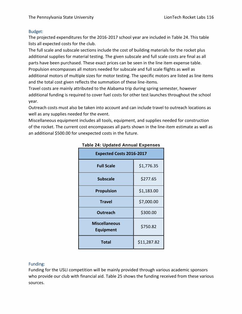
The Pennsylvania State University LionTech Rocket Labs 116
Budget: The projected expenditures for the 2016-2017 school year are included in Table 24. This table
lists all expected costs for the club.
The full scale and subscale sections include the cost of building materials for the rocket plus
additional supplies for material testing. The given subscale and full scale costs are final as all
parts have been purchased. These exact prices can be seen in the line item expense table.
Propulsion encompasses all motors needed for subscale and full scale flights as well as
additional motors of multiple sizes for motor testing. The specific motors are listed as line items
and the total cost given reflects the summation of these line-items.
Travel costs are mainly attributed to the Alabama trip during spring semester, however
additional funding is required to cover fuel costs for other test launches throughout the school
year.
Outreach costs must also be taken into account and can include travel to outreach locations as
well as any supplies needed for the event.
Miscellaneous equipment includes all tools, equipment, and supplies needed for construction
of the rocket. The current cost encompasses all parts shown in the line-item estimate as well as
an additional $500.00 for unexpected costs in the future.
Table 24: Updated Annual Expenses
Expected Costs 2016-2017
Full Scale $1,776.35
Subscale $277.65
Propulsion $1,183.00
Travel $7,000.00
Outreach $300.00
Miscellaneous
Equipment $750.82
Total $11,287.82
Funding: Funding for the USLI competition will be mainly provided through various academic sponsors
who provide our club with financial aid. Table 25 shows the funding received from these various
sources.

The Pennsylvania State University LionTech Rocket Labs 117
The Aerospace Department of Penn State has been the main sponsor of LTRL and they will
continue to support our club this year. They have agreed to provide a donation of $5,000.00.
The Mechanical Department of Penn State has also agreed to support our club due to the large
number of mechanical students involved. They have provided a donation of $1,000.00 to the
club.
This year our club is proud to have received the Samuel A. Shuman Endowment in Engineering.
This endowment is given to groups who work to advance education in engineering as well as
improve the students experience. The money from this endowment will go directly towards the
USLI Competition and travel to Alabama in order to provide our members with the best
experience possible. This endowment was given to LTRL in the amount of $8,700.00.
Yearly dues and fundraising opportunities gathered throughout the school year will also provide
funding on the scale of around $1,500.00.
The Boeing Company has supported our club in the past and has agreed to give a donation of
$500.00 for this school year.
Since the club has received the Samuel A. Shuman Endowment in Engineering, there is no
longer a need to continue to pursue additional sources of income. The income received this
year has been very substantial and will easily cover our expected costs for this year’s
competition. The club also hopes to save some funding to jumpstart our preparation for next
year’s competition. Even though the club have been very successful in receiving funding this
year, LTRL still wishes to continue developing new and existing relationships with academic
departments. The Mechanical Engineering Department at Penn State supported our club this
year and they are one department that LTRL wishes to solidify a relationship with in order to
plan ahead for future years. The College of Engineering and Engineering Undergraduate Council
(EUC) are two groups that have been contacted and seem interested in helping fund the club in
future years. Again the club plans to develop relationships with these groups in order to
diversify our funding pool for the future.
Due to LTRL’s success in acquiring additional funding, our goals for the year have been
expanded in order to further student participation, learning, and development. LTRL is currently
looking into ways to do this that may include more club launches of the current and past
subscale rockets, as well as club driven research or activities aimed towards expanding
students’ knowledge of rocketry. NAR certifications are another example of how the club will
continue to encourage students to diversify their experience within the club beyond one
specific subsystem.

The Pennsylvania State University LionTech Rocket Labs 118
Table 25: Expected Income
2016-2017 Income
Aerospace Engineering Department $5,000.00
Mechanical Engineering Department $1,000.00
Samuel A. Shuman Endowment in Engineering $8,700.00
Club Fundraising $1,500.00
The Boeing Company $500.00
Total $16,700.00

The Pennsylvania State University LionTech Rocket Labs 119
Project Timelines
Figure 40: Executive Timeline Page 1 of 4

The Pennsylvania State University LionTech Rocket Labs 120
Figure 41: Executive Timeline Page 2 of 4

The Pennsylvania State University LionTech Rocket Labs 121
Figure 42: Executive Timeline Page 3 of 4

The Pennsylvania State University LionTech Rocket Labs 122
Figure 43: Executive Timeline Page 4 of 4

The Pennsylvania State University LionTech Rocket Labs 123
Figure 44: A&R Timeline Page 1 of 2

The Pennsylvania State University LionTech Rocket Labs 124
Figure 45: A&R Timeline Page 2 of 2
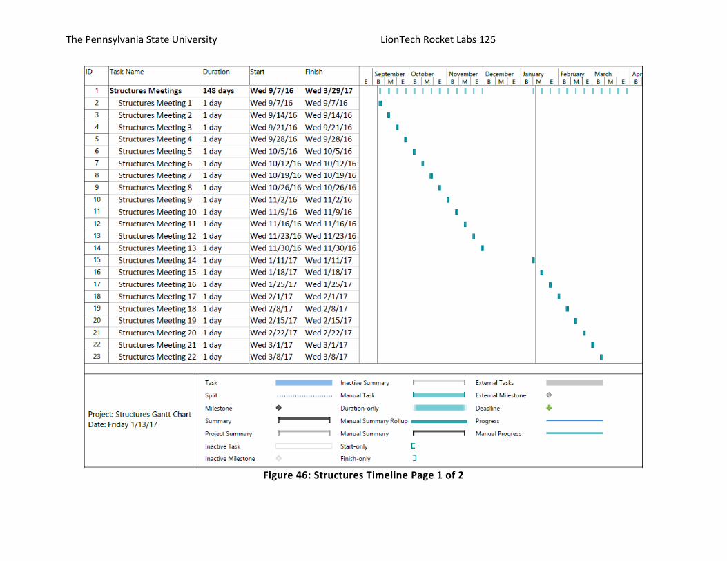
The Pennsylvania State University LionTech Rocket Labs 125
Figure 46: Structures Timeline Page 1 of 2
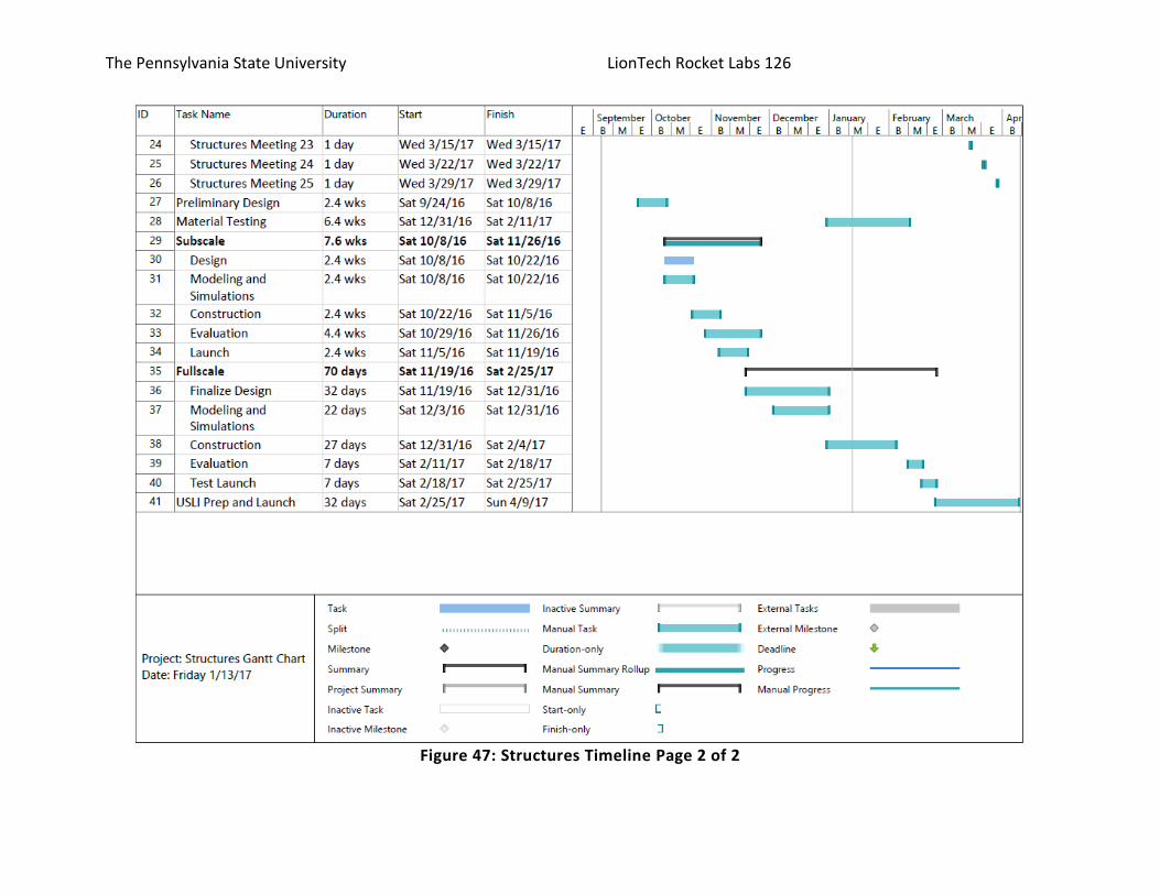
The Pennsylvania State University LionTech Rocket Labs 126
Figure 47: Structures Timeline Page 2 of 2

The Pennsylvania State University LionTech Rocket Labs 127
Figure 48: Propulsion Timeline Page 1 of 2

The Pennsylvania State University LionTech Rocket Labs 128
Figure 49: Propulsion Timeline Page 2 of 2

The Pennsylvania State University LionTech Rocket Labs 129
Figure 50: Payload Timeline Page 1 of 2

The Pennsylvania State University LionTech Rocket Labs 130
Figure 51: Payload Timeline Page 2 of 2

The Pennsylvania State University LionTech Rocket Labs 131
[1] Polymaker, "Polymax PLA Technical Data Sheet," 2015. [Online]. Available: http://www.polymaker.com/wp-content/uploads/2015/06/PolyMax-PLA_TDS-v1.pdf. Accessed: Nov. 1, 2016. [2] Glenn Research Center, "Velocity during recovery," in NASA Glenn Research Center, 2008. [Online]. Available: https://www.grc.nasa.gov/WWW/k-12/VirtualAero/BottleRocket/airplane/rktvrecv.html. Accessed: Oct. 29, 2016. [3] Arconic Corporation, "5052 and 6061 Aluminum Sheet," 2010. [Online]. Available: http://www.arconic.com/mill_products/catalog/pdf/alcoa_insert_5052and6061_final.pdf. Accessed: Nov. 3, 2016. [4] PerfectFlite, "SL100 Altimeter," in PerfectFlite Altimeters, 2015. [Online]. Available: http://www.perfectflite.com/sl100.html. Accessed: Oct. 28, 2016. [5] Y. A. Cengel and J. M. Cimbala, Fluid mechanics: Fundamentals and applications. Boston, MA:
McGraw-Hill Higher Education, 2006, sec. Drag Coefficients of Common Geometries, p. 573.
[6] G. Crowell Sr., The Descriptive Geometry of Nosecones. Instituto de Fisica de Sao Carlos, 1996.
[Online]. Available:
https://web.archive.org/web/20110411143013/http://www.if.sc.usp.br/~projetosulfos/artigos/NoseCo
ne_EQN2.PDF. Accessed: Oct. 22, 2016.
[7] Çengel, Yunus A., and John M. Cimbala. "Drag Coefficients of Common Geometries." Fluid Mechanics: Fundamentals and Applications. Boston: McGraw-Hill Higher Education, 2006. 573.
Works Cited

The Pennsylvania State University LionTech Rocket Labs 132
Appendix A: RECOVERY DESCENT PROFILE CALCULATOR

The Pennsylvania State University LionTech Rocket Labs 133

The Pennsylvania State University LionTech Rocket Labs 134

The Pennsylvania State University LionTech Rocket Labs 135
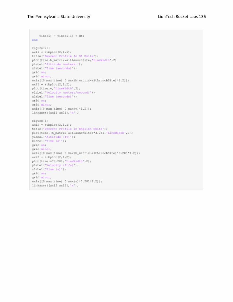
The Pennsylvania State University LionTech Rocket Labs 136

The Pennsylvania State University LionTech Rocket Labs 137

The Pennsylvania State University LionTech Rocket Labs 138

The Pennsylvania State University LionTech Rocket Labs 139

The Pennsylvania State University LionTech Rocket Labs 140
Appendix B: MSDS for Black Powder

The Pennsylvania State University LionTech Rocket Labs 141

The Pennsylvania State University LionTech Rocket Labs 142

The Pennsylvania State University LionTech Rocket Labs 143
001094

The Pennsylvania State University LionTech Rocket Labs 144
001095

The Pennsylvania State University LionTech Rocket Labs 145

The Pennsylvania State University LionTech Rocket Labs 146
001096

The Pennsylvania State University LionTech Rocket Labs 147
Appendix C: MSDS for Pyrodex

The Pennsylvania State University LionTech Rocket Labs 148

The Pennsylvania State University LionTech Rocket Labs 149
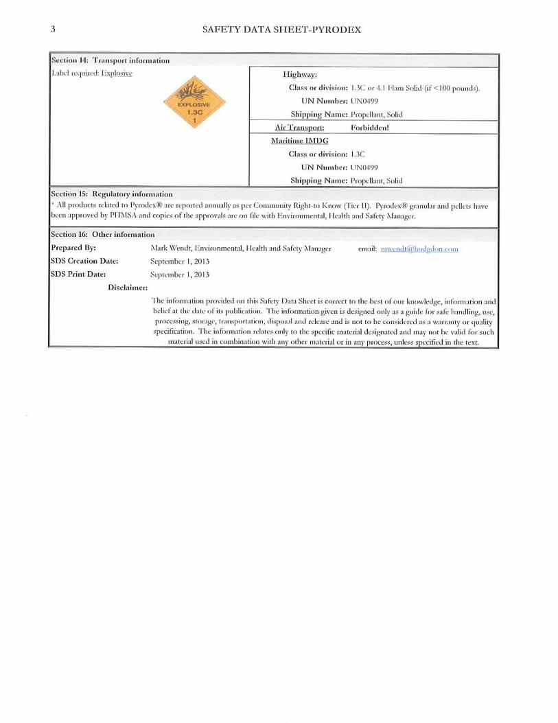
The Pennsylvania State University LionTech Rocket Labs 150