Embed Size (px)
Citation preview

Purdue UniversityPurdue e-Pubs
ECE Technical Reports Electrical and Computer Engineering
7-1-1992
USING THE EXTRA STAGE CUBEMULTIPATH NETWORK TO REDUCE THEIMPACT OF HOT SPOTSMu- Cheng WangPurdue University School of Electrical Engineering
Howard Jay SiegelPurdue University School of Electrical Engineering
Mark A. NicholsPurdue University School of Electrical Engineering
Seth AbrahamPurdue University School of Electrical Engineering
Follow this and additional works at: http://docs.lib.purdue.edu/ecetr
This document has been made available through Purdue e-Pubs, a service of the Purdue University Libraries. Please contact [email protected] foradditional information.
Wang, Mu- Cheng; Siegel, Howard Jay; Nichols, Mark A.; and Abraham, Seth, "USING THE EXTRA STAGE CUBE MULTIPATHNETWORK TO REDUCE THE IMPACT OF HOT SPOTS" (1992). ECE Technical Reports. Paper 295.http://docs.lib.purdue.edu/ecetr/295

USING THE EXTRA STAGE CUBE
MULTIPATH NETWORK TO REDUCE
THE IMPACT OF HOT SPOTS
TR-EE 92-25 JULY 1992
THIS RESEARCH WAS SUPPORTED BY THE NAVAL OCEAN SYSTEMIS CENTER UNDER THE HIGH PERFORMANCE COMPUTING BLOCK, O N T .

USING THE: EXTRA STAGE CUBE MULTIPATH NETWORK TO REDUCE THE IMPACT OF HOT SPOTS
Mu- Cheng Wang
Howard Jay Siege1
Mark A . Nichols
Seth Abraham
Parallel Processing Laboratory School of Electrical Engineering
Purdue University West Lafayette, IN 47907-1285 USA
July 1992
Purdue University, School of Electrical Engineering Technical Report TR-EE 92-25
This research was supported by the Naval Ocean Systems Center under the Hig,h Performance Computing Block, ONT.

Abstract
One type of interconnection network for a medium to large-scale parallel processing sys-
tem (i.e., a system with 26 to 216 processors) is a buffered packet-switched multistage
interconnection network (MIN). It has been shown that the performance of these net-
works is satisfactory for uniform network traffic. More recently, several studies have
indicated that the performance of MINs is degraded significantly when there is hot spot
traffic, that is, a large fraction of the messages are routed to one particular destination.
A multipath MIN is a MIN with two or more paths between all source and destination
pairs. This research investigates how the Extra Stage Cube multipath FvlIN can reduce
the detrirrlental effects of tree saturation caused by hot spots. Simula.tion is used to
evaluate the performance of the proposed approaches. The objective of this evaluation
is to show that, under certain conditions, the performance of the network. with the usual
routing scheme is severely degraded by the presence of hot spots. With the proposed
approaches, although the delay time of hot spot traffic may be increased, the perfor-
mance of the background traffic, which constitutes the majority of the network traffic,
can be significantly improved.

1. In t roduc t ion
A variety of approaches to the design of an interconnection network that supports
communication among the processors and memories of a medium to large-scale parallel
processing system (i.e., a system with 26 to 216 processors working together to solve a
problem) have been proposed and/or implemented. These approaches are often based
on a multistage interconnection network (a) topology consisting of multiple stages of
interchange boxes. A multistage cube network has been used or proposed for use in sys-
tems capable of MIMD operations such as the BBN Butterfly Plus [CrG85], BBN GP
1000 [BBN88], IBM RP3 [PfE385], PASM [SiNgO, SiS871, and NYU Ultracomputer
[GoG83]. The class of multistage cube network topologies includes: baseline [WuF80],
butterfly [CrG85], delta (a=b=2) [Pat81], flip [Bat76], generalized cube [SiN89], indirect
binary n-cube [Pea77], multistage shuffle-exchange [ThN81], omega [Law75], and SW-
banyan (S=F=2, L=n) [LiM87] networks [SieSO, WuF80j. Here, the class of multistage
cube networks will be represented by the generalized cube topology.
Let N be the number of processors in a multiprocessor system anti n be the size
(number of input and output ports) of the network interchange boxes used. The advan-
tages of the multistage cube network approach include: the number of network com-
ponents is proportional to Nlog,N, efficient distributed control schemes, network parti-
tionability, variations on the generalized cube topology make available multiple simul-
taneous source/destination paths [AdA87], and the ability to employ a variety of
different implementation techniques [SieOO]. Previous studies (e.g., 'DiJf.31, KrS83,
YoL901) have shown that packet-switched MINs can provide reasonable performance
with small-sized interchange box buffers when a moderate traffic load of uniform net-
work traffic is assumed. These advantages, coupled with good overall network perfor-
mance, make an MIN topology appealing [SiN89].
A physically distributed memory system composed of processors, memory, and a
buffered packet-switched network is assumed in this study (see Figure I). One processor
and its associated memory module form a processing element (PE). I t if3 assumed that
memory on all PEs is accessed as a single shared address space. Similar system
configurations can be found in the IBM RP3 [PfE385] and BBN Butterfly Plus [CrG85].
PEs satisfy memory references through the network if the referenced address is not
located on the attached memory module. From the viewpoint of a program, the only
difference between a reference to memory on the local P E and memory on. another P E is
that the remote reference takes more time to complete.

i Network
0 i I Processor H Interface
1 PEO 1
t I 1 ,,-,--,,,,,--------- d
I w l Network
PE N-1 f I
Figure 1: A physically distributed memory multiprocessor system.
A common network traffic model employed within MIN performance studies is one
where the stream of memory requests from each PE to all of the memory modules is
independent and identically distributed. However, this uniform traffic model does not
capture the effect of traffic requests to a single shared variable, for inst'ance, when the
shared variable is used for interprocess synchronization, e.g., a semaphore. When a
significant fraction of traffic is being directed a t a single destination PE, causing a "hot
spot" [PfN85], the network performance is degraded substantially due t;o a number of
the network buffers becoming saturated during a short period of time.
This research investigates how a multipath MIN (i.e., a MIN with two or more
paths between P E source and destination pairs) can reduce the effects of network buffer
saturation caused by hot spots. The multiprocessor systems assumed herein support lim-
ited multitasking, so, when a job encounters a hot spot, the system can perform a
context-switch that preempts the current job for another one that is not processing a hot
spot. The main idea behind the approaches proposed here is to use the extra paths to
balance the network traffic when a hot spot occurs. The target network considered in
this research is the extra stage cube (w), which has exactly two disjoint paths between
any source and destination [AdA87, AdS82, SieOO]. The performance of each of the pro-
posed approaches (i.e., the mean delay time for both the uniformly distributed traffic
and the hot, spot traffic) was evaluated by simulation. The objective of this evaluation is
to show that, under certain conditions, the performance of the network with the usual
routing scheme is severely degraded by the presence of hot spots. With the proposed
approaches, although the delay time of hot spot traffic may be increased, the perfor-
mance of the background traffic, which constitutes the majority of the network traffic,
can be significantly improved.

Researchers have considered the use of extra stage networks for fault tolerance (e.g.,
[YoH86]) and performance improvement under a uniform distribution assumption
[ChH84]. The goal of the study presented here is different: to develop techniques that
can, under the operating environment assumptions made, use the extra stage to improve
performance when a hot spot occurs.
The following section will introduce the topology and operating policy of the ESC
network. Section 3 will describe the assumed operating environment and will discuss
how system performance is degraded by hot spots. Then, three approaches proposed to
reduce the adverse effects of hot spots are described and evaluated in Section 4. Section
5 summarizes the results.
2. Relevant Details of Network Model Used
The ESC [AdA87, AdS82, SieOCl] is a multipath MIN and is formed from the multi-
stage cube network topology [SiN89] by adding an extra stage to the input side of the
network, a.long with multiplexers and demultiplexers a t the input (extra) stage and out-
put stage, respectively. In addition, dual 1/0 links to and from the devices using the
network are required.
In the ESC network, PE j sends data into the network through network input port
link j and receives data from network output port link j. For each n :< n interchange
box, the m-th interchange box output link, 0 I m < n, has the same link number as
the m-th interchange box input link. There are log,N + 1 stages, numbered from log,N
to 0, each containing N/n interchange boxes. For 0 I i < log,N, each interchange box
a t stage i of the network has n input links that differ only in the i-th base n digit of their
link numbers. Each interchange box in stage log,N, also referred to as the extra stage
or input stage, is connected like the output stage (stage 0) and has n input links which
differ only in the 0-th base n digit of their link numbers. As a result, when traversing
the ESC, only stages log,N and 0 can move a message from an interchange box input
link to an interchange box output link that differs in the 0-th base n digit of the link
label.
Figure 2 shows an ESC network with N = 8 inputs and outputs, 2 :< 2 interchange
boxes (i.e., n = 2), and four stages. The input stage and output stage can each be
enabled or disabled (bypassed). A stage is enabled when its interchange boxes are being
used to provide interconnection; i t is disabled when its interchange boxes are being
bypassed. The ESC with 2x2 interchange boxes is designed to tolerate any single fault
and is robust in the presence of multiple faults [AdS84].

Stage 3 2 1 0
(8)
Figure 2: (a) ESC network for N = 8; (b) input stage enabled; (c) input stage disabled;
(d) output stage disabled; (e) output stage enabled.
Normally, the network will be set so that the input stage is disabled and the output
stage is enabled. The resulting structure matches that of the multistage cube network.
Enabling both the input stage and output stage provides two disjoint paths between any
source and destination. The ESC can be controlled in a distributed fashiion by a simple
extension of the routing tags used for the multistage cube network.
In this study, a packet-switched ESC network is assumed. Each interchange box is
assumed to have a finite buffer associated with each output port. Each ornutput buffer in
an interchange box has a capacity of S fixed length packets. During each network cycle,
one packet is transferred from a nonempty output buffer of an interchange box to an
output buffer in the next stage. Each PE memory module can accept a packet from the
network each network cycle.
Each output buffer can accept up to n requests from input ports sirnultaneously if
there is enough space available for those requests. Because each output buffer is finite,
there is a conflict when the number of incoming packets destined for the same output

port exceeds the current packet space available for that buffer by R L 1 packets. To
solve the conflict, R randomly chosen packets are blocked. A blocked packet will remain
in the previous stage output buffer and will be resubmitted during the next cycle. To
insure message preservation throughout the system, there is an infinite buffer associated
with each PE. This buffer can hold blocked messages that cannot enter he network due
to insufficient buffer space. Consequently, no PE-generated messages will be discarded.
Several variations on the basic interchange box buffer design are possible [KaH86,
TaF881. Only output buffers with the first in first out (FIFO) policy aire considered in
this research. The degradation produced by hot spots is inherent to the blocking opera-
tion of the network, which is, in general, present for any buffering policy [LaKSO]. More-
over, the proposed approaches are applicable to other organizations, such as those in
[KaH86, TaF88j.
3. Hot Spots
It is usually assumed that memory requests are randomly directed a t the network
outputs (e.g., [DiJSl, KrS83, YoL90]), which is actually a reasonable assumption.
Although the requests generated by PEs cooperating on a single problem are not
independent, the presence of a large number of PEs and a number of different problems
(e.g., a multi-tasking environment) will tend to randomize the data requests. Also, the
hardware or software can hash (map) logical to physical memory locations, thereby
guaranteeing that requests appear random and are distributed across all memory
modules [GoG83]. There is, however, one exception: multiple memory requests gen-
erated from different PEs can be directed a t the same memory word during a short
period of time. I t is possible for such requests to be queued up a t the associated memory
module, which then becomes a bottleneck. Recall that n is the size of the interchange
boxes used,. When the output queue in a stage i interchange box is full, it can cause the
queues in t,he n stage i + 1 interchange boxes that feed it to fill. In turn., those n stage
i + 1 interchange boxes can cause the n2 interchange boxes feeding them .to fill. Eventu-
ally, a tree of saturated interchange boxes results, with the stage 0 inte.rchange box a t
the congested memory module as the root. Tree saturation degrades the performance of
all PEs in a system, including those not accessing the congested memory nnodule. Such a
memory module has been termed a hot spot [PfN85] and has been studlied by various
researchers (e.g., [PfB85, KuP86, YeT871).
Hot spots can occur for many reasons. I t is assumed in this study that a hot spot in
a multiprocessor system is the result of a global synchronization operation. In the rest of
this discussion, the global synchronization requests are denoted as synchrclnization traffic

and the remaining uniform traffic as background traffic. The background traffic can be
subdivided into hot background traffic and nonhot background traffic. These are back-
ground traffic destined and not destined for the hot spot memory module:, respectively.
Naturally, all PEs will not request global synchronization at the sa.me time (other-
wise, synchronization would not be necessary). The distribution of global synchroniza-
tion requests is modeled by a normal distribution, characterized by mean p and standard
deviation a (as in [AbP89]). Values for these parameters depend on the details of the
multiprocessor implementation and the specific application under consideration. When
a is close to zero, the synchronization requests will be generated in a single cycle; as it
increases, the hot spot traffic distribution will eventually resemble the background traffic
distribution.
To perform a global synchronization, all PEs in the system will independently send
a synchronization message to a specific P E called the coordinator. When N - 1 of these
requests have been received by the coordinator, all PEs in the system are informed via a
broadcast that the synchronization operation is complete. To increase both system per-
formance and job throughput and to reduce P E idle time, it is assume~d that each P E
will continue other work while the synchronization message is in progress. One way to
do this is to perform a job context switch. More precisely, the job issuing the global
synchronization request will be put into the waiting queue (i.e., the job will be deac-
tivated) and another job in the ready queue will become activated during; the next cycle.
This permits the PEs to start computation on another job while the previous job waits
for its global synchronization request to be fully processed. Thus, by performing a job
context switch, it is assumed that each P E will continue to generate background traffic
a t a constant rate irrespective of whether any global synchronization operation is in pro-
gress (e.g., [PfN85, YeT871). I t is assumed that the architecture is designed for fast con-
text switches (e.g., HEP [Kow85]), so that context switch time is much smaller than the
time to fully process a global synchronization request.
It is assumed also, for simplicity, that there is only one synchronization operation in
existence a t a time (as in [AbP89]). Each must be completely finished before another
one can begin. Because a multitasking environment is assumed, there is no reason to
prohibit other active jobs from issuing synchronization requests. It is done here to sim-
plify the simulations and analysis. However, because of the structure of the proposed
approach to reduce degradation due to a single hot spot, the approalch will also be
beneficial in the case of multiple hot spots.

Many different approaches, such as the combining networks proposed for the IBM
RP3 [PfBBS] and NYU Ultracomputer [GoG83], or the repetition filter m.emory proposed
for the Columbia CHoPP [SuB77], have been suggested to eliminate the hot spot prob-
lem. The basic idea of these schemes is to incorporate some hardware in the intercon-
nection network to trap and combine data accesses if they are directed a t the same
memory location and they meet at a specific interchange box. The delay time experi-
enced by a request traversing a buffered multistage network enhanced with combining
under hot spot traffic has been studied in [Lee89, KaLSl]. Combining :requests reduces
communication traffic and thus decreases the average amount of queue space used,
which leads to a lower average network delay time. However, the hardware required for
such schemes is extremely expensive [PfN85]. An inexpensive approach proposed in
[YeT87] uses a software combining tree to decrease memory contention a~nd prevent tree
saturation by initially distributing a single synchronization operation over many memory
modules, and then combining collections of synchronization signals. In t,his approach, a
hot spot request must traverse the interconnection network more than once, whereas in a
hardware combining network the request will traverse the network only once.
The use of feedback schemes in a MIN with distributed routing control to reduce
degradation to memory requests not destined for the hot spot was proplosed in [ScS89].
In this approach, each processor avoids sending requests destined for a hot module into
the network if tree saturation is detected. If these problem-causing requests can be held
outside the network, the severity of the tree saturation problem can be reduced.
Another approach to alleviate the impact of tree saturation, proposed in [Tzegl],
employs multiple queues at each interchange box input port (one separate queue for each
interchange box output port). Every interchange box has a fixed amount of storage.
Each queue in an interchange box is permanently allocated a slot and also shares avail-
able storage with other queues in an interchange box dynamically; no siingle queue may
exhaust the entire storage pool. Thus, it can sustain the nonhot-spot traific flow even in
the presence of saturation trees and thereby improve the overall network performance.
The approach proposed herein differs from the above schemes by using a multipath
MIN to reduce the interference between synchronization and background traffic. The
goal of this paper is to demonstrate the potential of this multipath MIN approach. It is
very difficult, and beyond the scope of this paper, to directly compare this scheme with
all of the various previously proposed methods due to the differences in hardware costs
and traffic models.

4. Proposed Approach
4.1. Definitions of P a r a m e t e r s
In this subsection, parameters to be used are defined. Table 1 summarizes most of
these parameters.
Because there is only one unique path associated with each source/destination pair
in the multistage cube network [SiN89], a message will suffer a long delay if it must go
through the saturated area in the network caused by a hot spot. There are multiple
paths available for a message if an ESC network is used. However, the existence of mul-
tiple paths through the network may not alleviate this problem if each message chooses
its routing path independently. Even with dynamic rerouting, as congestion begins, the
messages to the hot spot will themselves be rerouted and in the steady state will saturate
all the alt,ernative paths [PfN85]. If all synchronization messages are forced to choose
some predetermined path to the destination and if the background messages can use
alternate paths that do not involve any interchange boxes in the saturated area, as pro-
posed here, the delay time of background messages can be improved significantly. The
saturation tree problem cannot be completely eliminated by separating the background
and synchronization traffic when they traverse through the network because the com-
bined arrival rates of the synchronization and background traffic still exceed the hot spot
processing rate. Thus, the hot spot will remain the bottleneck of the network. Most
synchronization messages will be enqueued inside the network before being processed.
However, the research herein shows that the interference between the ;synchronization
and background traffic can be reduced significantly under this condition. The goal of
this research is to improve the delay time of the background traffic when a hot spot
occurs.
The performance measures addressed in this study are the average delay time of
synchronization messages (pSYN), the average delay time of all background messages
( , Y ~ ~ ( ~ ~ ~ ) ) , and the average delay time of hot background messages ( / J ~ ~ ( ~ ~ ) ) . Let y be -- -
the background traffic generation rate and assume 0 5 y < 1, i.e., on average, each PE
will generate a message during any cycle with probability y. Background message gen-
eration a t a P E is nondeterministic and is independent of that a t any other PE.
Let DTt(i) denote the delay time for message i of type t, where t refers to either --
synchronization (i.e., t = SYN) or background traffic (i.e., t = BG). Due to the FIFO
policy assumed, a message will wait in a P E or interchange box output buffer until all
messages in front of it have been serviced. Thus, the delay time of a message is the total
time a message spends waiting in the output buffers of a P E and the ESC network inter-
change boxes (exclusive of traversal time). That is, DTt(i) = {the time message i of type
t arrives a t the destination) - {the time it is generated) - {interchange box traversing
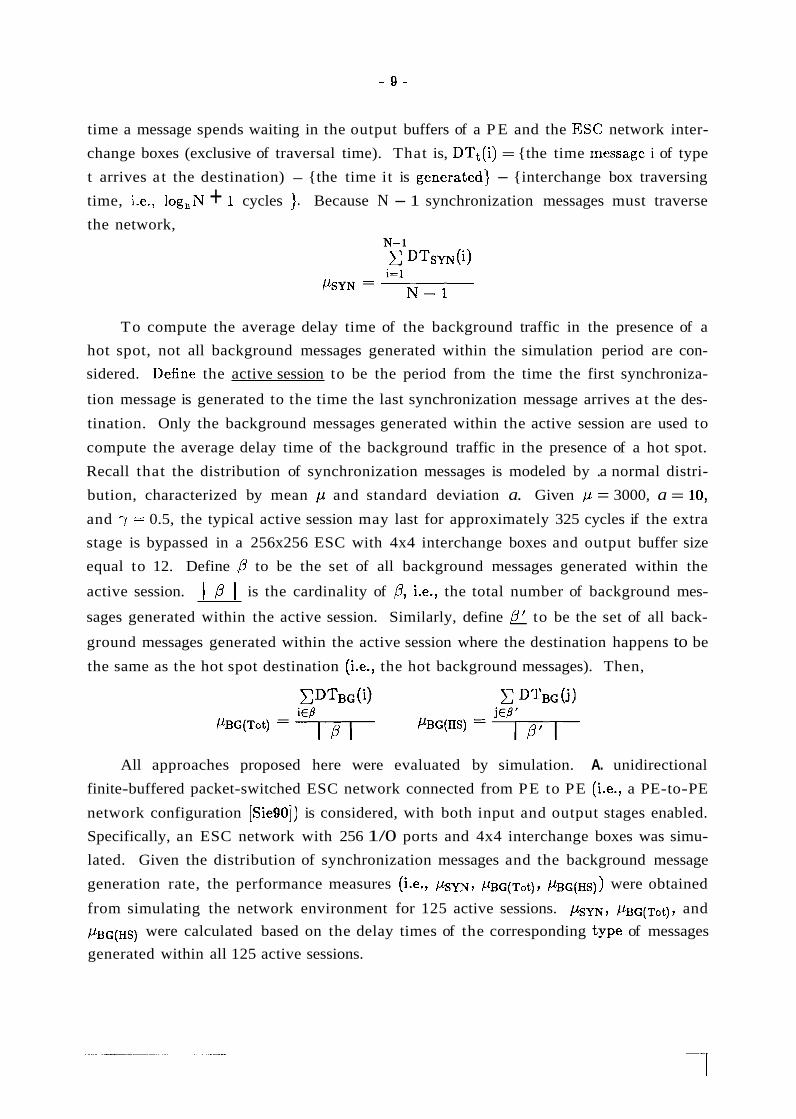
time, i-e., log,N + 1 cycles ). Because N - 1 synchronization messages must traverse
the network,
To compute the average delay time of the background traffic in the presence of a
hot spot, not all background messages generated within the simulation period are con-
sidered. Define the active session to be the period from the time the first synchroniza-
tion message is generated to the time the last synchronization message arrives a t the des-
tination. Only the background messages generated within the active session are used to
compute the average delay time of the background traffic in the presence of a hot spot.
Recall that the distribution of synchronization messages is modeled by .a normal distri-
bution, characterized by mean p and standard deviation a. Given p = 3000, a = 10,
and 7 = 0.5, the typical active session may last for approximately 325 cycles if the extra
stage is bypassed in a 256x256 ESC with 4x4 interchange boxes and output buffer size
equal to 12. Define - P to be the set of all background messages generated within the
active session. 1 p I is the cardinality of P, i.e., the total number of background mes-
sages generated within the active session. Similarly, define P' to be the set of all back- - ground messages generated within the active session where the destination happens to be
the same as the hot spot destination (i.e., the hot background messages). Then,
All approaches proposed here were evaluated by simulation. A. unidirectional
finite-buffered packet-switched ESC network connected from PE to PE (i.e., a PE-to-PE
network configuration [SiegO]) is considered, with both input and output stages enabled.
Specifically, an ESC network with 256 1/0 ports and 4x4 interchange boxes was simu-
lated. Given the distribution of synchronization messages and the background message
generation rate, the performance measures (i.e., hm, P B G ( T ~ ~ ) , ~BG(HS): I were obtained
from simulating the network environment for 125 active sessions. km, P B G ( T ~ ~ ) , and
/LBG(HS) were calculated based on the delay times of the corresponding type of messages
generated within all 125 active sessions.

Given a source and destination pair, there are n paths that are dist'inct from stages
log,N - 1 to 1 in terms of the boxes (and associated links) used [AdS82, SieSO]. The
input stage allows a message to select one of these paths from source to destination.
Formally, it can be described as follows. Recall that for 1 i i i log,N - 1, each inter-
change box a t stage i of the network has n input links that differ only in the i-th base n
digit of their link numbers. Each interchange box in the input and output stages has n
input links that differ only in the O-th base n digit of their link numbers. Thus, only the
input and output stages can move a message from an interchange box 'input link to an
interchange box output link that differs in the O-th base n digit of the link label. Conse-
quently, once the input stage output link has been selected for a message, this output
link label and all link labels of every interchange box traversed by the message from
stages logzN - 1 to 1 have the same O-th base n digit. Because there are n output links
available fbr a message a t the input stage, there are n paths (including bloth interchange
boxes and links) that are distinct from stages log2N - 1 to 1. Thus, to determine the
routing pa.th for a message, only the setting of the input stage interchange boxes is con-
sidered in the following discussion.
No tat ion Meaning I number of processors in a parallel system I
capacity of an interchange box output buffer I size of the network interchange box I
mean and standard deviation of the synchronization messages I set of background messages generated within the active session I
number of background messages generated within the active session
set of hot background messages generated within the active session
number of hot background messages generated within the active session / background traffic generation rate I
average delay time of the synchronization messages
average delay time of all background messages
average delay time of the hot background messages p p p p p
Table 1: Summary of notation used throughout the paper.
4.2. The. Isola ted Background Messages Approach
A synchronization message is pending if a PE has generated a synchronization mes-
sage and is still waiting for the response. It is assumed that a local hot spot flag is asso-
ciated with each PE, and is set to indicate there is a pending synchronization request in
that PE. The global synchronization response can be broadcast from 1;he coordinating
P E only if all N - 1 synchronization messages have been received. Oncle the synchroni-
zation message's response arrives, the local hot spot flag will be reset.
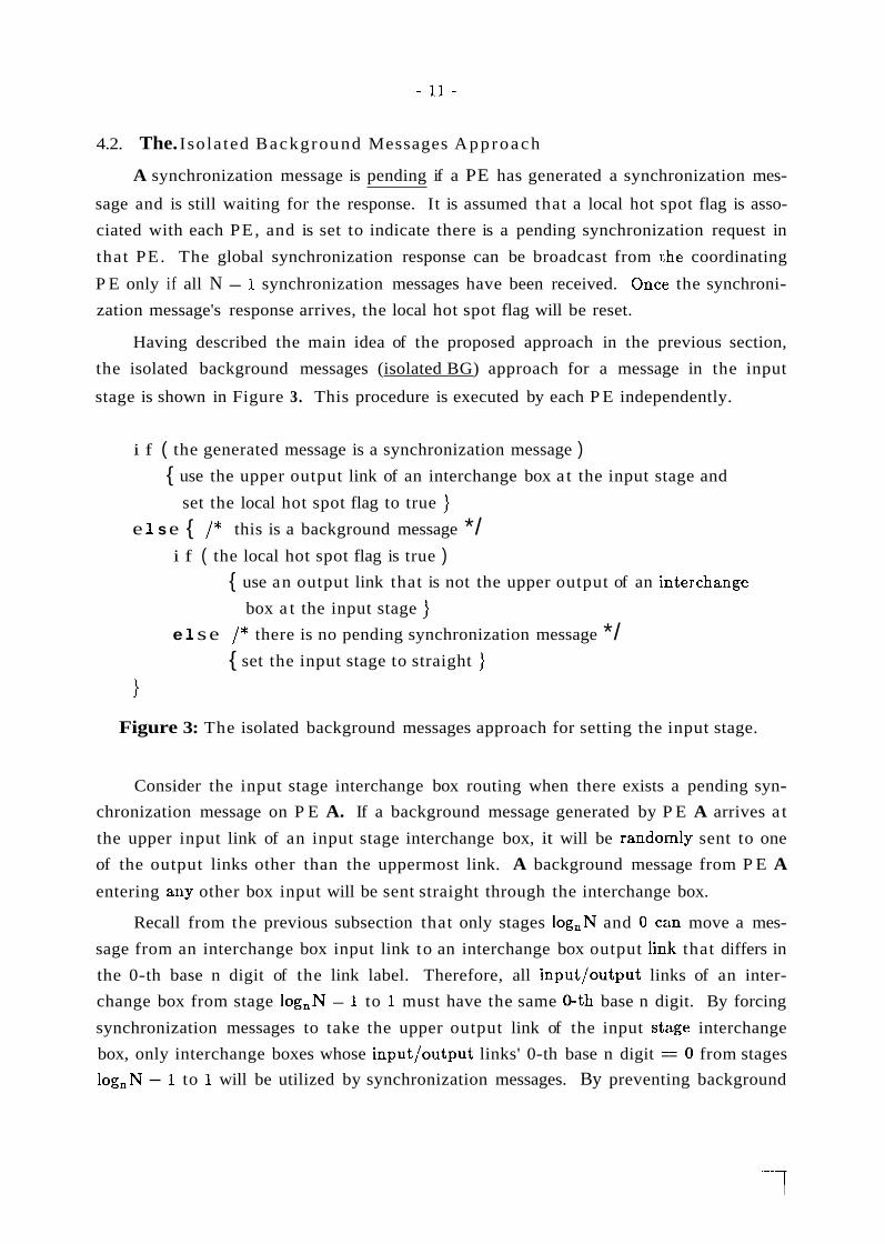
Having described the main idea of the proposed approach in the previous section,
the isolated background messages (isolated BG) approach for a message in the input
stage is shown in Figure 3. This procedure is executed by each P E independently.
i f ( the generated message is a synchronization message ) { use the upper output link of an interchange box a t the input stage and
set the local hot spot flag to true ) e 1 s e { /* this is a background message */
i f ( the local hot spot flag is true ) { use an output link that is not the upper output of an i:nterchange
box a t the input stage ) e 1 s e /* there is no pending synchronization message */
{ set the input stage to straight )
1 Figure 3: The isolated background messages approach for setting the input stage.
Consider the input stage interchange box routing when there exists a pending syn-
chronization message on P E A. If a background message generated by P E A arrives a t
the upper input link of an input stage interchange box, it will be rando~nly sent to one
of the output links other than the uppermost link. A background message from P E A
entering any other box input will be sent straight through the interchange box.
Recall from the previous subsection that only stages log,N and 0 cetn move a mes-
sage from an interchange box input link to an interchange box output 1in:k that differs in
the 0-th base n digit of the link label. Therefore, all input/output links of an inter-
change box from stage log,N - 1 to 1 must have the same 0-th base n digit. By forcing
synchronization messages to take the upper output link of the input stage interchange
box, only interchange boxes whose input/output links' 0-th base n digit == 0 from stages
log,N - 1 to 1 will be utilized by synchronization messages. By preventing background

messages from taking the upper output link of the input stage interchange box, no inter-
change boxes whose input/output links' 0-th base n digit = 0 from stages log,N - 1 to
1 will be used by background messages. Because stages log,N - 1 to 0 form a multi-
stage cube network topology, all network outputs are reachable from any stage
log,N - 1 interchange box.
Figure 4 shows the routing paths for both synchronization and background mes-
sages in a.n 8x8 ESC network with 2x2 interchange boxes. Because the upper output
link a t each interchange box in the input stage is reserved for synchronization messages,
the interchange boxes marked with "S" in Figure 4 are used by synchronization mes-
sages exclusively. In a similar fashion, the interchange boxes marked with "B" are used
by background messages exclusively.
Stage 3 2 1 0
(a)
Figure 4: The routing paths for (a) synchronization and (b) background messages.
To evaluate the performance of this approach, a 256x256 ESC network was simu-
lated, assuming 4x4 interchange boxes and an interchange box output buffer size of 12
packets. Different background traffic generation rates (7) were simuliated using two
different routing schemes: bypassing the input stage and the isolated BG approach
described in Figure 3. The former approach incurs no time delay for the input stage in
the simulations, and is equivalent to using a standard multistage cube network (i.e., con-
structed without an extra stage). I t also corresponds to how the ESC could be used nor-
mally when there are no faults. In this simulation, the distribution of :synchronization

messages was modeled by a normal distribution with /L = 3000 and a == 10. The meas-
ures being analyzed were p s y ~ , / L B G ( T ~ ~ ) , and ~ B G ( H S ) . These simulation results are
show11 in Figure 5.
120 'BG(Hs)
(in cycles) 90
250 - 140 - Isolated BG Approach
120 - 220 -
loo - 190 -
%YN 'BG,, 80 - (in cycles)
160 - (in cycles) 60 - 40 -
130 Bypass Extra Stage 20 -4
4
Bypass Extra Stage
- Isolated BG Approach
Bypass Extra Stage / Isoliited BG Approach
Figure 6: The average delay time, for N = 256, n = 4, S = 12, and tr = 10, of a (a) synchronization message, p ~ y ~ ; (b) background message, / L B G ( T ~ ~ ) ; and (c) background message to the hot spot, ~ G ( H S ) . The values on the vertical axes vary among the three graphs.
l o o l . l . l . l . l . l . l 0.2 0.3 0.4 0.5 0.6 0.7 0.8 0 4 0.2 /+/ 0.3 0.4 0.5 - 0.6 0.7 0.8
Y Y (a> (b)
As can be seen, the average delay time of the background traflic ( / L ~ ~ ( ~ ~ ~ ) ) is
reduced significantly when compared to the bypassing scheme. This is because the
interference between synchronization and background messages has been reduced. It is
quite interesting to notice that ~ B G ( H S ) > p ~ y ~ when the bypassing scheme is used.

Recall that the distribution of background messages is modeled by a uniform distribu-
tion rather than the normal distribution used for synchronization messages. Consistent
with the definition of the active session, the simulations show that most synchronization
messages arrive at the network input ports earlier than background messages generated
within the active session. An example of this is provided in Figure 6. Thus, these back-
ground messages need to wait in the network buffers until the synchronization messages
in front of them have been processed. However, when employing the isolated BG
approach, there is no interference between the synchronization and background messages
from stages log,N to 1. The paths chosen by the hot background messages are less
congested than the paths chosen by the synchronization messages. Thus, these back-
ground messages can arrive a t the destined interchange box a t stage 0 earlier than the
synchronization messages can. Consequently, /LBG(HS) < /LSYN when the isolated BG
.approach is used.
0 synchronizat:ion hot background
- I I I I ' J J I - 2970 2980 2990 3000 3010 3020 3030 3295 cycles
Time
Figure 6: Number of synchronization and hot background message:; generated per
cycle during the active session.
While / L B G ( T ~ ~ ) is reduced by the isolated BG approach, the average delay time of a
synchronization message is increased. This is because by using the isolated BG
approach, there exists some competition between the synchronization messages and hot
background messages when arriving a t the destined interchange box a t the output stage.
This competition is relatively small when the bypass scheme is used because most hot

background messages are enqueued after the synchronization messages. As stated above,
with the isolated BG approach the hot background messages will arrive at the output
stage sooner and therefore create more interference. Thus, extra delay is expected for
the synchronization messages when the isolated BG approach is employed.
Whecher it is reasonable to sacrifice synchronization message delay time to improve
the delay time of background messages is dependent on which one is more important to
users. The number of synchronization messages is N - 1 and it takes at least N - 1
cycles to accept all synchronization messages at the destination. (The actual time to
accept all the synchronization messages is dependent on the interference between the
backgrourld and synchronization traffic and the way synchronization messages are gen-
erated, i.e., 0.) Thus, by definition, the active session is at least N - I eycles long. The
total number of background messages generated within the active session equals
N x y x ( time of active session I 1 N x y x (N - 1) -- ~ ~ x y , if N is large. For
N x y >> 1, it is obvious that the number of synchronization messages is relatively
small compared to the number of background messages. Thus, this approach increases
the average delay of the N - 1 synchronization messages, but it reduces the delay of at
least N' >: 7 background messages by approximately the same amount. Because the
value of this trade-off depends on the tasks being executed, it can be applied whenever
the user deems it appropriate.
When investigating the simulation results for the isolated BG approach, it is
interesting to note that the delay time of hot background messages is much larger than
that of other background messages. It implies that, other than the saturation tree
directly caused by the synchronization messages, there exists another saturation tree
starting from the interchange box connected to the hot spot in the network. Regarding
Figure 4, the original saturation tree would occur within the "S" subnetwork, whereas
this secondary saturation tree would occur within the "B" subnetwork. The secondary
tree is caused mainly by the hot background messages, because these messages need to
compete with the synchronization messages when arriving at the output buffer of the
interchange box at the output stage. Because conflicts are assumed to be resolved fairly,
the hot background messages cannot always win the competition. Thus, the hot back-
ground messages will be enqueued at the previous stage, which in turn will form the
secondary saturation tree. Dependent on the background message generation rate, the
secondary saturation tree can also block and slow down other messages that are not des-
tined for the hot spot. Thus, the average delay time of the background traffic can be
reduced further if the secondary saturation tree can be removed.

4.3. The Iaolated Hot Spot Messages Approach
An approach that will eliminate the secondary saturation tree is described in this
subsectio~i. This approach is called the isolated hot spot messages (bolated HS) algo-
rithm. It is the same as the isolated BG approach, except that when a synchronization
message is pending, all hot background messages are routed through the upper output
links of the input stage interchange boxes (as are all the synchronization messages).
Define the synchronization messages and hot background messages to be the
hot spot messages. The isolated HS algorithm is presented in Figure 7 . As with the iso-
lated BG approach described in the previous subsection, this proced.ure is executed
independently by each PE.
i f ( the generated message is a synchronization message ) { use the upper output link of an interchange box a t the input stage and
set the local hot spot flag to true ) else { /* this is a background message */
i f ( the local hot spot flag is true ) { i f ( destination address = = hot spot address )
{ use the upper output link of an interchange box a t the input stage ) e 1 s e /* destination address # hot spot address */
{ use an output link that is not the upper output of an interchange
box a t the input stage }
e 1 s e /* there is no pending synchronization message */ { set the input stage to straight )
Figure 7: The isolated hot spot messages approach for setting the input stage.
The isolated HS approach was evaluated by simulation and the network environ-
ment was assumed to be the same as in the previous subsection. The performance meas-
ures for p ~ m , ~ B G ( T ~ ~ ) , and ~ B G ( H S ) under different background traffic gleneration rates,
y, are shown in Figure 8.
It can be seen from this figure that p s m is reduced significantly vvhile ~ B G ( H S ) is
increased significantly when compared with the results from the isolated1 BG approach.
As discussed in the previous subsection, most synchronization messages will be generated
before the hot background messages. Therefore, with the isolated HS approach,

140 - 250 -
Isolated BG Approach
220 - loo -
(in cycles) Isolated BG Approach
Isolated HS Approach
Bypass Extra Stage l o o r . 1 . 1 . 1 . 1 . 1 . 1
0.2 0.3 0 .4 0.5 0.6 0.7 0.8 0 .2 0.3 0 .4 0.5 0.6 0.7 0.8 * I
(in cycles) 90
-
Isolated HS Approach
Figure 8: The average delay time, for N = 256, n = 4, S = 12, and (T = 10, of a (a) synchronization message, psm; (b) background message, ~ B G ( T ~ ~ ) ; and (c) background message to the hot spot, ~ B G ( H S ) . The values on the vertical axes vary among the three graphs.
synchronization messages will precede hot background messages in the saturation tree.
In the isolated BG approach, the routing paths taken by the hot background messages
are less congested than the paths taken by the synchronization messages. The hot back-
ground messages can arrive at the destination earlier than some synchronization mes-
sages even when they are generated after those synchronization messages. Thus, ~ B G ( H S )
is smaller and , + j y ~ is greater in the isolated BG approach when compared with the
delay time in the isolated HS scheme.

Because the maximum service rate at the hot spot is fixed, while the delay time of
the hot background traffic is increased in the isolated HS approach, the delay time of
synchronization messages is reduced. Recall the destinations of background messages are
uniformly distributed, and that the total number of background messages generated is:
I ,l? I = y x active session I x N.
The number of hot background messages ( I ,8' I ) is ( P I IN (i.e., just those messages
destined for the hot spot output port). As previously stated, for N = 256, n = 4, S = 12,
a = 10, and y = 0.5, lactive session1 was typically 325 cycles. Thus, I ,l?' ) = 162.5
messages. For realistic physically distributed memory systems, it is expected that
7 i 0.5 (i.e., typically, a remote memory access is generated at most very other cycle).
Thus, depending on the background message generation rate, 10' ) will typically be
smaller than or comparable to the number of synchronization messages (which is N).
Therefore, it is reasonable to sacrifice those background messages to impirove the average
delay time of the synchronization messages. Also, from the simulation results, the
existence of the secondary saturation tree when using the isolated BG approach is
confirmed because the average delay time of all background messages is reduced by
using the isolated HS approach (Figure 8(b)). This occurs especially when the back-
ground traffic generation rate is high.
Notice that as y increases, the hot background messages (Figure 8(c)) experienced
more delay than the synchronization messages (Figure 8(a)) with either the bypass or
isolated HS approach. For example, for the bypass scheme with a = 10 and y = 0.5, the
delay for the hot background messages ( / . L ~ ~ [ ~ ~ ~ ) was 151, which is 30% more than the
delay for synchronization messages (psm = 116). This phenomenon occurs because of
the different distribution assumptions for synchronization and background messages.
Most of the hot background traffic is introduced into the network after all of the syn-
chronization messages have already caused the congestion as shown in Figure 6. Because
both classes of messages use the same routing paths, both will experience significant
delays relative to the nonhot background messages.
From Figure 8(a), it is interesting to note that with the isolated HS approach, psm is larger than the corresponding average delay in the bypass scheme. Also, with the iso-
lated HS approach, ~ B G ( H S I is reduced when compared to the bypass scheme as shown in
Figure 8(c:). This phenomenon is a result of the following.
Defint: the height of the saturation tree (Ht) - to be the length (number of arcs) of the
longest path from the root to a leaf node. The saturation tree is completely balanced if
it has ni nodes a t depth i, where 0 I i I Ht. Recall that within the active session,

most of the hot background messages are generated after all of the synchronization mes-
sages. Ideally, most of the hot background messages will not be received a t the destined
node until all synchronization messages have been accepted. However, if the saturation
tree is not, completely balanced, a hot background message may arrive at a nonleaf node
X while there are still some synchronization messages enqueued in other subtrees of node
X. Both classes of messages will use the same path from node X to the hot spot. Thus,
those synchronization messages will be delayed by one network cycle by the hot back-
ground message. For example, consider a hot background message M, that arrives a t
leaf node B at depth i, where i < Ht as shown in Figure 9. MI needs to wait a t an out-
put buffer of node B until all messages in front of it have been served. When M1 is
accepted by the parent node A, the synchronization messages enqueued in other subtrees
(e.g., in nodes C and F) will be delayed by one cycle. For the bypass case, if M1 is a
nonhot ba.ckground message, it will have less impact on the delay of the synchronization
messages compared to the case when it is a hot background message. This is because
nonhot baxkground messages will leave the saturation tree eventually (i.e., they are not
going to the hot spot).
Figure 9: The saturation tree in an ESC network with 4x4 interchange boxes.
To delay any synchronization messages, a hot background message must enter a
nonleaf node early enough such that there are still some synchronirration messages
enqueued in other subtrees of that node. Although the nonhot background messages
have less impact on the delay of the synchronization messages, they can block the hot
background messages in the bypass case.
With the isolated HS approach, only synchronization messages and :hot background
messages are allowed to use the reserved subnetwork. However, with the bypass scheme,
the network is shared by all messages. The number of nonhot background messages that
must traverse the saturation tree will increase (compared to the isolated 'HS case), which

causes the hot background traffic to be blocked. Consequently, the possiibility that a hot
background message can interfere with the synchronization messages is reduced. Thus,
the isolated HS approach provides more opportunity for the hot background messages to
delay the synchronization messages. It is expected that h y ~ will be larger in the iso-
lated HS approach than in the bypass scheme. For hot background messages, if the
chance to delay the synchronization messages is increased, more messages can traverse
the network without suffering a long delay. Consequently, ,UBG(HS) is reduced.
4.4. The. H o t Section Approach
Recall that N denotes the network size and n is the interchange box size. In both
the isolated BG and isolated HS approaches, the first output link of an interchange box
a t the input stage is reserved for synchronization messages. Thus, only (n - l)/n of the
total output links a t the input stage can be used to transfer the nonhot E~ackground mes-
sages (once the local PE has a pending synchronization message). Consequently, only
(n - l)/n of the total interchange boxes a t each stage (from stage log,N - 1 to stage 1)
can be used by the nonhot background messages. For example, if n is equal to two, only
half of the interchange boxes from stage logaN - 1 to stage 1 can be used by the back-
ground traffic (see Figure 4(b)) and that is quite undesirable. When n = 2 and the back-
ground message generation rate is greater than 0.5, the net message arrival rate to the
lower output queue a t each interchange box in the input stage is greater .than one, which
exceeds the maximum service rate that an output queue can support. Therefore, the
input stage itself becomes the new bottleneck in the ESC network under ;such conditions.
As n increases, the percentage of input stage output links reserved for synchronization
messages decreases, and the percentage available for nonhot background .traffic increases.
In general, for the isolated BG approach, the average number of background messages
arriving a t a single input interchange box output link is 7n/(n - 1). Thus, when
.yn/(n - 1) > 1, or equivalently, y > (n - l)/n, the maximum service rate is exceeded.
For the isolated HS approach, 1 / N of the background messages are destined for the hot
spot and ].outed through the upper output link. Consequently, the generation rate of
nonhot background messages is 7(l - (l/N)). When 7(l - ( l /N)) :> (n - l)/n, or
equivalently, y > ((n - l ) / n ) ( ~ / ( ~ - I)), the maximum service rate is exceeded. By
increasing the interchange box size, the input stage bottleneck problem can be reduced
to some extent.
Although l /n of the interchange boxes from stage log,N - 1 to stage 1 in an ESC
network are reserved for synchronization messages, not all such reserved interchange
boxes are actually utilized. Due to the saturation tree structure property and the
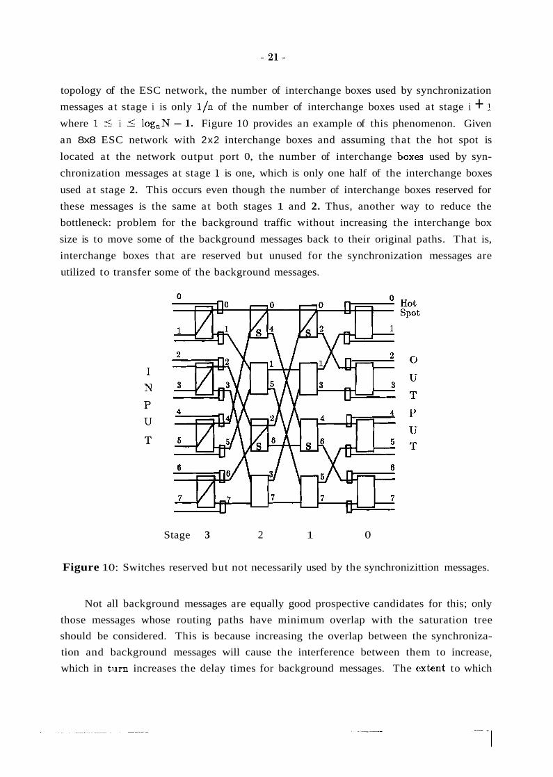
topology of the ESC network, the number of interchange boxes used by synchronization
messages a t stage i is only l/n of the number of interchange boxes used at stage i + 1
where 1 5 i i log,N - 1. Figure 10 provides an example of this phenomenon. Given
an 8x8 ESC network with 2x2 interchange boxes and assuming that the hot spot is
located at the network output port 0, the number of interchange box.es used by syn-
chronization messages a t stage 1 is one, which is only one half of the interchange boxes
used a t stage 2. This occurs even though the number of interchange boxes reserved for
these messages is the same at both stages 1 and 2. Thus, another way to reduce the
bottleneck: problem for the background traffic without increasing the interchange box
size is to move some of the background messages back to their original paths. That is,
interchange boxes that are reserved but unused for the synchronization messages are
utilized to transfer some of the background messages.
Stage 3 2 1 0
Figure 10: Switches reserved but not necessarily used by the synchronizittion messages.
Not all background messages are equally good prospective candidates for this; only
those messages whose routing paths have minimum overlap with the saturation tree
should be considered. This is because increasing the overlap between the synchroniza-
tion and background messages will cause the interference between them to increase,
which in turn increases the delay times for background messages. The extent to which

the routing path of a background message is overlapped with the saturation tree is
dependeni; on the location of the hot spot, the source and destination of the background
message, the size of the saturation tree, the output buffer size, and the interchange box
size used.
Let the network outputs be partitioned into K sections of equal siae, where K is a
power of two, and let the i-th section for 0 I i < K contain the N/K network outputs
i(N/K) + j , for 0 I j < N/K. Denote the section including the hot spot to be the
hot section. With the hot section approach there are three cases to consider when rout-
ing background messages given a local pending synchronization message. The first case
occurs when there is a hot background message; it is routed through the upper output
link of the input stage interchange box. In the second case, a background message is
destined for the hot section (but not the hot spot); it is forced to rancdomly select an
input stage interchange box output link other than the upper one. The last case is a
backgr0un.d message not destined for the hot section; it is simply routed straight through
the input stage interchange box. The hot section approach differs from the isolated BG
and isolatt?d HS approaches for input stage routing in that nonhot background messages
can be routed through the upper output link of an input stage interchange box. As a
result of this difference a t the input stage, the hot section approach differs from the first
two in later stages in that nonhot background messages can make use of interchange
boxes in the hot spot subnetwork. This makes use of hot spot subnetwork interchange
boxes that are left idle with the first two approaches (such as the stage 1 box with links
4 and 6 in Figure 10).
If K equals one, there is only one hot section and all network outputs are resident in
the hot section. Thus, l/n of the ESC network is reserved for synchroni:sation messages
and only lhot background messages can use any of those reserved interchange boxes.
This situation is identical to the isolated HS approach described in the previous subsec-
tion. However, if K equals N, the hot section includes only the hot spot, and all nonhot
background messages simply go straight across the input stage (i.e., no int,erchange boxes
are reserved exclusively for synchronization messages). In addition to sojme background
messages, the upper output link of an interchange box a t the input stage is also used to
deliver sy~lchronization messages, causing the upper output link to be overloaded.
Depending on the background traffic generation rate, i.e., y, the distribution of the syn-
chronization messages, i.e., a, the output buffer size, i.e., S, and the interchange box size
used, i.e., :n, an optimal K value between one and N should exist. When the network
environmelit is known, the optimal K value can be determined via simu1at;ion.

Stage 3 2 1 0
Figure 11: The hot section when K = 2.
Consider an 8x8 ESC network with 2 x 2 interchange boxes and assume that the
hot spot is located at output port 0 (see Figure 11). If K is chosen to be two, all network
outputs are partitioned into two sections and the hot section includes the output ports 0,
1, 2, and 3. By using the idea discussed above, a background message generated by an
even-numbered PE (i.e., PEs 0, 2, 4, or 6) and not destined for the hot section must go
through a reserved interchange box at stage 2, then enter the reserved but unused inter-
change box at stage 1. Depending on the parameters mentioned previously, the messages
will make use of idle reserved interchange boxes and avoid the most congested portions
of the saturation tree. Thus, this approach will increase the utilization of the inter-
change boxes reserved for synchronization messages and balance the network traffic
more evenly.
Based on this idea, the isolated HS approach can be modified and is presented in
Figure 12 as the hot section approach. Similar to the schemes proposed in the previous
two subsections, this approach is executed independently by each PE.
By simulating a 256x256 network with 4x4 interchange boxes and setting the back-
ground message generation rate (7) equal to 0.7 and 0.8, the average delay times for
background and synchronization traffic were evaluated for different K values. Figure 13
shows the delay time of synchronization messages (pSYN), background messages
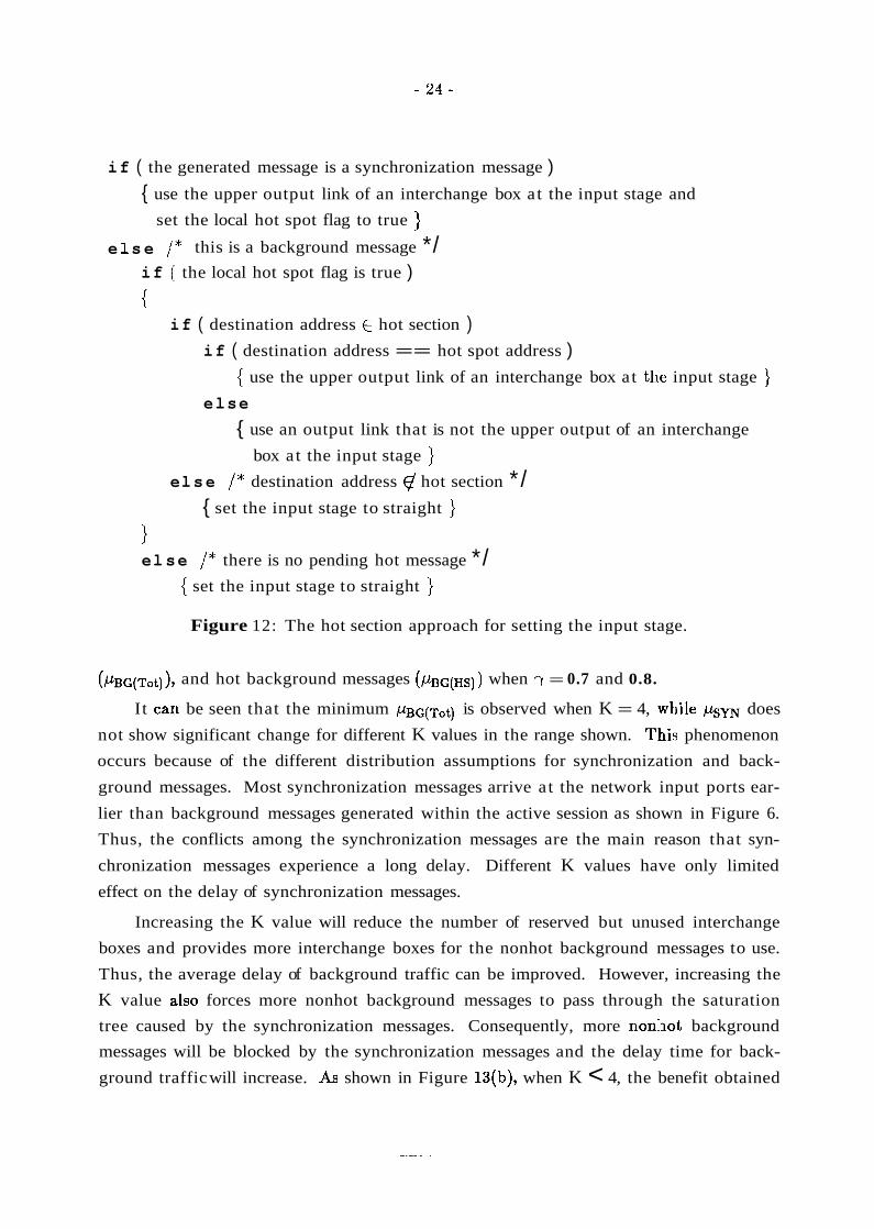
if ( the generated message is a synchronization message )
{ use the upper output link of an interchange box at the input stage and
set the local hot spot flag to true } e 1 s e / * this is a background message */
if the local hot spot flag is true )
{ if ( destination address E hot section )
if ( destination address == hot spot address ) { use the upper output link of an interchange box at the input stage }
else
{ use an output link that is not the upper output of an interchange
box at the input stage } el s e / * destination address @ hot section * /
{ set the input stage to straight }
1 el se / * there is no pending hot message */
{ set the input stage to straight }
Figure 12: The hot section approach for setting the input stage.
( / L ~ ~ ( ~ ~ ~ ) ) , and hot background messages ( / L ~ ~ ( ~ ~ ) ) when 7 = 0.7 and 0.8.
It can be seen that the minimum *G(Tot) is observed when K = 4, .while / L S ~ does
not show significant change for different K values in the range shown. T:his phenomenon
occurs because of the different distribution assumptions for synchronization and back-
ground messages. Most synchronization messages arrive a t the network input ports ear-
lier than background messages generated within the active session as shown in Figure 6.
Thus, the conflicts among the synchronization messages are the main reason that syn-
chronization messages experience a long delay. Different K values have only limited
effect on the delay of synchronization messages.
Increasing the K value will reduce the number of reserved but unused interchange
boxes and provides more interchange boxes for the nonhot background messages to use.
Thus, the average delay of background traffic can be improved. However, increasing the
K value a.1~0 forces more nonhot background messages to pass through the saturation
tree caused by the synchronization messages. Consequently, more nonhot background
messages will be blocked by the synchronization messages and the delay time for back-
ground traffic will increase. As shown in Figure 13(b), when K < 4, the benefit obtained
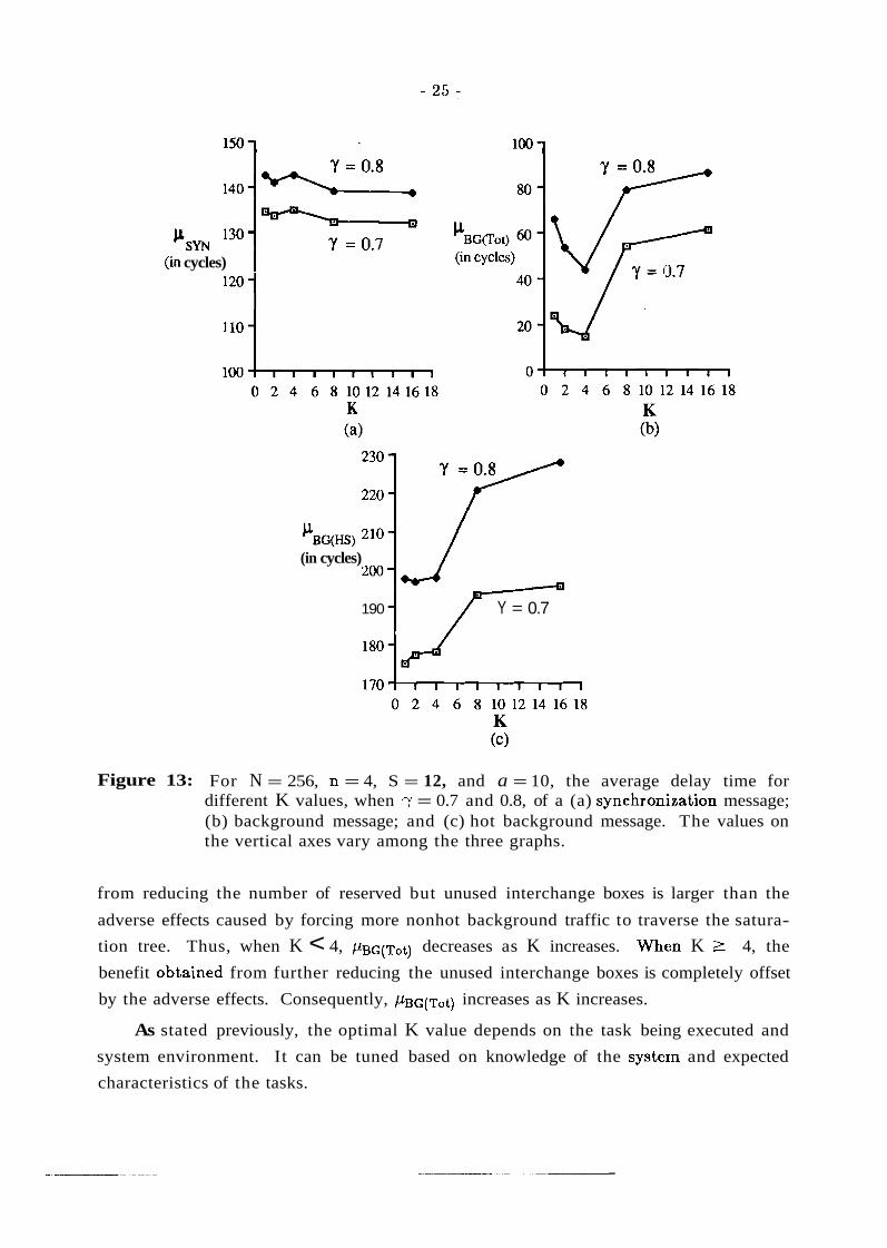
(in cycles) I
(in cycles)
190 Y = 0.7
Figure 13: For N = 256, n = 4, S = 12, and a = 10, the average delay time for different K values, when y = 0.7 and 0.8, of a (a) synchroni.zation message; (b) background message; and (c) hot background message. The values on the vertical axes vary among the three graphs.
from reducing the number of reserved but unused interchange boxes is larger than the
adverse effects caused by forcing more nonhot background traffic to traverse the satura-
tion tree. Thus, when K < 4, decreases as K increases. Whm K L 4, the
benefit obiained from further reducing the unused interchange boxes is completely offset
by the adverse effects. Consequently, &c(Tot) increases as K increases.
As stated previously, the optimal K value depends on the task being executed and
system environment. It can be tuned based on knowledge of the systern and expected
characteristics of the tasks.

To evaluate the performance of the hot section approach, an ESC network with the
same configuration described above was simulated. Different distributions of synchroni-
zation messages (a) and background traffic generation rates (y) were simulated using two
different routing schemes: bypassing the input stage and the hot section approach with
K = 4 . The measures being analyzed were C L ~ W , / L B G ( T ~ ~ ) , and p ~ c ( ~ s ) .
200 - 10 10
160 - ----C---- Bypass ex.tra stage
30 30
'BG(HS) 120 5 5 o o (in cycles)
80
40
- Hot section approach
Figure 14: For N = 256, n = 4, S = 12, and K = 4, the average delay time for different values of a for a (a) synchronization message; (b) backgrourld message; and (c) hot background message. The values on the vertical axes vary among the three graphs.
Similar to the isolated HS approach proposed in the previous subsection, with the
hot section approach, the overlap between the routing paths chosen by the

synchronization and background messages are reduced substantially. Thus, it is
expected and confirmed from the simulation results that with the hot section approach
the average delay time for a background message is much smaller than the delay time
with the bypass scheme.
Except for the impact of different values of a for the message delay time, the simu-
lation results shown in Figure 14 are similar to the results shown in Figlire 8 for the iso-
lated HS and bypass approaches and can be explained by the same reasons. As a
increases, the synchronization messages are generated within a wider range of network
cycles ancl eventually they will resemble the background traffic distribut,ion. Thus, as a
becomes larger, the saturation tree problem caused by the synchronization messages
becomes less serious, and consequently, p s m and ~ B G ( H S ) decrease substantially when
employing either the bypass or hot section approach (see Figure 14(a) and (c)). With the
bypass scheme, when the saturation tree problem becomes less serious, C L B G ( T ~ ~ ) becomes
smaller because more background messages can pass through the network without being
blocked b:y the saturation tree. However, with the hot section approach, there is only a
limited overlap between the routing paths chosen by the synchronization messages and
nonhot ba.ckground messages. Thus, the average delay time of a background message is
not affected significantly when increasing the value of a.
6. Message Delay Time Under Various Buffer Sizes
It is -well known that in a packet-switched multistage network with uniformly dis-
tributed network traffic, only a small-sized output buffer (e.g., buffer size of two or four)
is required to achieve the performance obtained from an infinite-sized output buffer
[DiJ81]. However, when a hot spot occurs, a significant improvement can be expected
when the size of the output buffer is large. This is because the numbel- of interchange
boxes occupied by the synchronization messages decreases as the buffer size increases,
effectively reduing the depth of the saturation tree. In this subsection, the effect of out-
put buffer size on background message delay is investigated for the byp;zss and hot sec-
tion approaches. Recall that the message delay time is measured beginning a t the time a
message is generated by a PE (even if it cannot yet enter the network).
Figures 15, 16, and 17 show bm, / .LBG(T~~) , and & G ( H ~ ) , respectively, for different
values of cr as a function of different buffer sizes, when = 0.4 and 0.6. Both the bypass
scheme and the hot section approach with K = 4 were considered and evaluated. For
the range of S (the buffer size) considered, for each of km, ,LLBG(T~~), and ~ B G ( H S ) , the
relative performance of the bypass and hot section approaches is unchanged from Figure
14 (where S = 12). This occurs for the same reason as was indicated in the discussion of

Figure 14.
60' 80 -- 6 8 10 12 14 16 18 20 22 6 8 10 12 14 16 18 20 22
Buffer Size, S Buffer Size, S
(a> (b) - Bypass extra stage - Hot section approach
la!\ "--+I10 s!L
-V'O -30
.--:: w - w 50
130 -
110-
s (in cycles) 90 "
80
70
Figure 15: For N = 256, n = 4, and K = 4, the average de1;ay time of a synchronization message for different values of a and buffer sizes, when (a) ry = 0.4 and (b) ry = 0.6. The values on the vertical axes differ between the two graphs.
l 2 O i ~ ~ 130 -- 10
-
lW:-30 pSm 110-
-' 3 0 (in cycles) loo -
:--- 50 -, 50 90 -
It is quite interesting to note that with the hot section approach, -when increasing
the buffer size, psm decreases and /-LBG(Hs) increases as shown in Figures 15 and 17.
However, with the bypass scheme, both psm and ~ B G ( H S ) remain relatively stable when
increasing the buffer size. This phenomenon is discussed below.
Similar to the isolated HS approach, the hot section approach provitles more oppor-
tunity for hot background messages to delay the synchronization mess;sges when com-
pared to the bypass scheme. When increasing the buffer size, the height of the satura-
tion tree, Ht, is reduced and, consequently, the number of nonleaf nodes is decreased.
Recall that to delay a synchronization message, a hot background messa:ge must enter a
nonleaf node while some synchronization messages are still enqueued in other subtrees of
that node. With the hot section approach, the saturation tree mainly consists of hot
background and synchronization messages. Reducing the number of nonleaf nodes
implies that the opportunity for a hot background message to delay a synchronization
message is reduced. Consequently, hy~ is reduced as the buffer size increases. Because
fewer hot background messages can traverse the saturation tree without being blocked
by the synchronization messages, I -~~G(Hs) increases.

P BG(T0t)
(in cycles)
' g o ( T O t 1 (in cycles)
Buffer Size, S
(a)
Buffer Size, S
(b) - Bypass extra stage - Hot section approach
Figure 16: For N = 256, n = 4, and K = 4, the average delay time of a background message for different values of a and buffer sizes, when (a) 7 = 0.4 and (b) 7 = 0.6. The values on the vertical axes differ between the two graphs.
With the bypass scheme, the saturation tree consists of synchronization messages
and background messages, including messages not destined for the hot spot. Thus, the
opportunity for a hot background message to arrive a t a nonleaf node while there are
still some synchronization messages enqueued in other subtrees is relatively small.
Increasing the buffer size reduces the number of interchange boxes used by the synchron-
ization messages, which will reduce the number of background messages being blocked,
and hence, reduces Ht. Thus, the possibility of a hot background message interfering
with a synchronization message is further reduced . However, with the bypass scheme,
the reason that ,usm is large is due mainly to the serialization effect a t the hot spot.
Thus, p s m is relatively unaffected by an increase in the buffer size as shown in Figure
15. Because most of the hot background messages are blocked by synclhronization mes-
sages even when the buffer size is small, the delay will not be further increased. Thus,
~ G ( H S ) remains stable as buffer size increases as shown in Figure 17.
With the bypass scheme, although varying the buffer size does not have a significant
effect on i 4 m and /LBG(HS), it can reduce the delay time of nonhot background messages
substantially as shown in Figure 16. This is because when the buffer size is increased,
the number of interchange boxes used by synchronization messages is reduced, and con-
sequently,, more nonhot background messages can pass through the network with less
blockage.

130
115
P BG(HS)
(in cycles) 85
6 8 10 12 14 16 18 20 22
Buffer Size, S
(a>
140
CL BG(HS) 120
(in cycles)
-/ e
80 - 60
6 8 10 12 14 16 18 20 22
Buffer S ix , S
(b)
-----t---- Bypass extra stage - Hot section approach
Figure 17: For N = 256, n = 4, and K = 4, the average delay time of a hot background message for different values of a and buffer sizes, when (a) y =
0.4 and (b) y = 0.6. The values on the vertical axes differ between the two graphs.
With the hot section approach, because the paths used by the non.hot background
messages are not usually congested, increasing the buffer size cannot significantly impact
those messages. Beginning with a buffer size of 12, the average delay time of a back-
ground message becomes relatively stable when increasing the buffer size. The main rea-
son for a message to be delayed is because there are messages in front of it in the local
interchange box buffer, rather than the destined buffer in the next stage being full.
Thus, increasing the buffer size further cannot significantly reduce the average delay
time of a 'background message.
As discussed above, it can be seen from Figure 16 that when using the bypass
scheme, the background traffic delay time decreases gradually as the buffer size (S)
increases. It is expected that the delay time would be improved if S is increased further.
Also, it is quite interesting to note that given the same traffic generation rate (y), the hot
section approach using a buffer size of eight can outperform the bypass scheme using a
buffer size of 20. Furthermore, the delay time for the hot section approa.ch starts to sta-
bilize when S 2 12. This implies that the hardware cost of an extra stage in an ESC
network may be offset by reducing the size of the output buffers. However, one impor-
tant benefit obtained from adding an extra stage to the multistage cube network is to
provide a fault tolerant capability when interchange boxes or links become faulty

[AdA87, AdS821. Thus, the additional hardware cost of an extra stage can be justified
when the benefits gained are considered.
8. Conclusion
This study examined techniques for using the ESC network to i~rnprove network
performance when hot spot situations occur. Simulation was used to evaluate the pro-
posed techniques under certain assumptions about the execution envirl~nment and the
network structure. The results of these simulations were reported and discussed.
In a multipath ESC network, if all synchronization messages are forced to choose
some predetermined path to the destination and if the nonhot background messages can
use the paths that do not involve any interchange boxes in the saturat'ed area or have
only limited overlap, the network performance can be improved significantly. Although
the proposed approaches may increase the delay time for the synchronization messages,
it substantially reduces the delay time of the background messages that constitute the
majority of the network traffic. Simulation results have shown that, for the operating
environmcmt assumptions made, the proposed schemes can be used to: (1) control tree
saturation. among network interchange box output buffers, (2) reduce the delay of
memory requests that are not to the hot memory module, and (3) increase overall system
bandwidth.
All analyses presented were based on the framework of a 256x256 ESC network
with 4x4 interchange boxes. Based on the reasoning used in the analysis of the simula-
tion results, the proposed approach should behave similarly for larger ESC networks. It
is expected that the same idea can be applied to other multipath netwlorks with minor
modifications. Furthermore, although a single shared address space was assumed here,
the techniqu-e is also applicable to message passing systems. Future iresearch on this
topic includes evaluating the proposed approaches under different operating environment
assumptions.
Acknowledgment
The authors acknowledge many useful discussions with Professor John K. Antonio,
Professor Jose A. B. Fortes, Dr. Wayne G. Nation, Mr. Gene Saghi, and Professor Ver-
non Rego.

References [AbP89] S. Abraham and K. Padmanabhan, "Performance of the direct binary n-cube
network for multiprocessors," IEEE Transactions on Computers, Vol. 38, No. 7, July 1989, pp. 1000-1011.
[AdA87] G. B. Adams 111, D. P. Agrawal, and H. J. Siegel, "A survey and comparison of fault-tolerant multistage interconnection networks," Cotnputer, Vol. 20, No. 6, June 1987, pp. 14-27.
[Ads821 G. B. Adams I11 and H. J. Siegel, "The extra stage cube: a fault-tolerant interconnection network for supersystems," IEEE Transactions on Comput- ers, Vol. C-31, No. 5, May 1982, pp. 443-454.
[Ads841 G. B. Adams I11 and H. J. Siegel, "Modifications to improve the fault toler- ance of the extra stage cube interconnection network," 1984 International Conference on Parallel Processing, August 1984, pp. 169-173.,
[Bat761 K. E. Batcher, "The flip network in STARAN," 1976 Inter:national Confer- ence on Parallel Processing, August 1976, pp. 65-71.
[BBN88] BBN Advanced Computers, Inc., Inside the GPl000, Cambridge, MA: BBN Advanced Computers, Inc., 1990.
(ChH841 C. Y. Chin and K. Hwang, "Packet switching networks for multiprocessors and data flow computers," IEEE Transactions on Computers, Vol. C-33, No. 11, November, 1984, pp. 991-1003.
[CrG85] W. Crowther, J. Goodhue, R. Thomas, W. Milliken, and T. Ellackadar, "Per- formance measurements on a 128-node butterfly parallel processor," 1985 International Conference on Parallel Processing, August 1985#, pp. 531-540.
[DiJ81] D. M. Dias and J. R. Jump, "Analysis and simulation of bu:ffered delta net- works," IEEE Transactions on Computers, Vol. C-30, Apri:l 1981, pp. 273- 282.
[GoG83] A. Gottlieb, R. Grishman, C. P . Kruskal, K. P. McAuliffe, 1,. Rudolph, and M. Snir, "The NYU Ultracomputer designing an MIMD shared-memory parallel computer," IEEE Transactions on Computers, Vol. C-32, No. 2, February 1983, pp. 175-189.
[KaH86] M. J. Karol, M. G. Hluchyj, and S. P. Morgan, "Input vs. output queueing on a space-division packet switch," IEEE Global Telecommunications Conference, December 1986, pp. 659-665.
[KaL9:l.] B.-C. Kang, G. Lee, and R. Kain, "Performance of multistage combining net- works," 1991 International Conference on Parallel Processin,g, August 1991, pp. 550-557.
[Kow85] J. S. Kowalik, Parallel MIMD Computation: The HEP Supercomputer and Its Applications, The MIT Press, Cambridge, MA, 1985.
(KrS83) C. P . Kruskal and M. Snir, "The performance of multistage interconnection networks for multiprocessors," IEEE Transactions on Computers, Vol. C-32, No. 12, December 1983, pp. 1091-1098.
[KuP86] M. Kumar and G. F. Pfister, "The onset of hot spot contention," 1986 Inter- national Conference on Parallel Processing, August 1986, pp. 28-34.
[LaK90] T. Lang and L. Kurisaki, "Nonuniform traffic spots (NUTS) in multistage interconnection networks," Journal of Parallel and Distributed Computing, Vol. 10, No. 1, September 1990, pp. 55-67.

D. H. Lawrie, "Access and alignment of data in an array processor," IEEE Transactions on Computers, Vol. C-24, No. 12, December 1975, pp. 1145- 1155. G. Lee, "A performance bound of multistage combining networks," IEEE Transactions on Computers, Vol. 38, No. 10, October, 1989, :pp. 1387-1395. G. J. Lipovski and M. Malek, Parallel Computing: Theory and Comparisons, John Wiley & Sons, New York, NY, 1987. D. S. Parker and C. S. Raghavendra, "The gamma network," IEEE Transac- tions on Computers, Vol. C-33, No. 4, April 1984, pp. 367-373. J. H. Patel, "Performance of processor-memory interconnection networks for multiprocessors ," IEEE Transactions on Computers, Vol. C-30, No. 10, October 1981, pp. 771-780. M. C. Pease 111, "The indirect binary n-cube microprocessor array," IEEE Transactions on Computers, Vol. C-26, No. 5, May 1977, pp. 458-473. G. F. Pfister, W. C. Brantley, D. A. George, S. L. Harvey, M7. J. Kleinfelder, K. P . McAuliffe, E. A. Melton, V. A. Norton, and J. Weiss, "The IBM Research Parallel Processor Prototype (RP3): introduction and architecture," 1985 International Conference on Parallel Processing, August 1985, pp. 764- 771. G. F. Pfister and V. A. Norton, "'Hot spot' contention and combining in multistage interconnection networks," IEEE Transactions on Computers, Vol. C-34, No. 10, October 1985, pp. 933-938. S. L. Scott and G. S. Sohi, "Using feedback to control tree saturation in multistage interconnection networks" 16th Annual Symposic~m on Computer Architecture, May 1989, pp. 167-176. H. J. Siegel, Interconnection Networks for Large-Scale Parallel Processing: Theory and Case Studies, Second Edition, McGraw-Hill, New York, NY, 1990. H. J. Siegel, W. G. Nation, C. P . Kruskal, and L. M. Napolitano, Jr., "Using the multistage cube network topology in parallel supercomputers," Proceed- ings of IEEE, Vol. 77, No. 12, December 1989, pp 1932-1953. H. J. Siegel, W. G . Nation, and M. D. Allemang, "The organization of the PASM reconfigurable parallel processing system," 1990 Palrallel Computing Workshop, sponsored by the Computer and Information Science Department a t the Ohio State University, 1990, pp. 1-12. H. J. Siegel, T. Schwederski, J. T. Kuehn, and N. J. Davis rV , "An overview of the PASM parallel processing system," in Computer Architecture, D. D. Gajski, V. M. Milutinovic, H. J. Siegel, and B. P. Furht, eds., IEEE Com- puter Society Press, Washington, DC, 1987, pp. 387-407. H. Sullivan, T. R. Bashkow, and K. Klappholz, "A large-scale homogeneous, fully distributed parallel machine," Fourth Annual Symposium on Computer Architecture, March 1977, pp. 105-124. Y. Tamir and G. L. Frazier, "High-performance multi-queue buffers for VLSI communication switches," 15th Annual Symposium on Cornputer Architec- ture, June 1988, pp. 343-354. S. Thanawastien and V. P. Nelson, "Interference analysis of shuffle/exchange networks," IEEE Transactions on Computers, Vol. C-30, No. 8, August 1981, pp. 545-556.

[Tzegl] N.-F. Tzeng, 'LAlleviating the impact of tree saturation on multistage inter- connection network performance," Journal of Parallel and Distr ibuted C o m - put ing, Vol. 12, No. 2, June, 1991, pp. 107-117.
[WuF80] C.-L. Wu and T. Y. Feng, "On a class of multistage interconnection net- works," IEEE Transac t i ons o n Compu te r s , Vol. C-29, No. 8, August 1980, pp. 694-702.
[YeT87] P. C. Yew, N. F. Tzeng, and D. H. Lawrie, "Distributing hot,-spot addressing in large-scale multiprocessors," IEEE Transac t i ons o n Comp,uters , VoI. C-36, No. 4, March 1987, pp. 388-395.
[YoH86] K. Yoon and W. Hegazy, "The extra stage gamma network," 1 9 t h A n n u a l S y m p o s i u m o n C o m p u t e r Archi tec ture , June 1986, pp. 175-182.
[YoL90] H. Yoon, K. Y. Lee, and M. T. Liu, 'LPerformance analysis of multibuffered packet-switching networks in multiprocessor systems," IEEE Transac t i ons o n Compu te r s , Vol. C-39, No. 3, March 1990, pp. 319-327.