Embed Size (px)
Citation preview

USER´S Manual
© HAKI AB 2021
HAKI Bridge System(HBS)

2
© Copyright HAKI AB, 2021The reproduct ion of text and pictures/illustrat ions without HAKI’s permission is prohibited.
Important informationHAKI’s product liability and user´s manuals apply only to scaffolds that are entirely composed of components that have been made and supplied by HAKI.
HAKI’s scaffold systems must not be erected using components of makes other than HAKI or be connected to scaffolds of makes other than HAKI. In such cases, a special study of load-bearing capacity must be carried out. However, HAKI has no objection to the customary addition of scaffold tubes and approved couplers to the scaffold.
Adding components from different suppliers may invalidate the insurance cover.
This user´s manual is based on a minimum of 2 competent erectors.
This user’s manual is to be used in conjunct ion with HAKI training courses.
A user’s manual should be provided to the user together with the scaffolding.
HAKI reserves the right to make technical modifications on a continual basis.
The latest versions of HAKI user’s manuals can be downloaded from our website, www.HAKI.com.
For scaffold structures that are not covered by this user´s manual, please contact HAKI’s technical department.
Forces and dimensions 1000 N = 1 kN ~ 100 kg 10 N ~ 1 kgAll measurements in mm
HAKI colour codeHorizontals and diagonals are marked with their nominal sizes (bay sizes) and a colour code. The marking is a useful means of ident ificat ion when erect ing and handling the scaffold material.
564 1050 1964 3050 700 1250 2050 3650 770 1550 2500 4050 1010 1655 2550

3
The HAKI Bridge System (HBS) is designed for loadings up to 7.5kN/m2. The HAKI Bridge System is designed to be used as a pedestrian bridge over rail tracks/roadways and similar projects, or to act as a spine beam for scaffolds, or to support temporary roofs. It is a perfect complement to the HAKI Public Access Stair (PAS).
All HAKI Systems have been designed to conform to current Brit ish and European Standards. The loading criteria contained in this manual have been calculated according to current European Standards, SS-EN 12810 and SS-EN 12811.
The HBS incorporates the use of HAKI Universal system components including the single ledgers, ledger beams, and guardrail frames. The handrails (barriers) are specially designed for use on a HBS and PAS system. All components for the HAKI Bridge System are hot-dip galvanized with the exception of the insert panels and AL planks.The HBS can be erected in bay widths of 1250mm, 1655mm, 1964mm or 2500mm (where permitted) and bay lengths of 2500mm or 1250mm with the minimum of tools.
The HBS may be constructed;1. on a temporary scaffold at ground level, then lifted into place.2. on a temporary scaffold at finished level.3. by a progressive ‘roll-out’ method.
BASIC INFORMATION
HAKI Bridge System (HBS)
General
All components, with the exception of locking catches, pins etc, come permanent ly marked with the HAKI logo and the last two figures of the year of manufacture ( S18).All load bearing components are marked for full traceability.
Marking
IMPORTANT
ENGAGE LOCKING CATCHES AS EACHCOMPONENT IS FIXED

4
BASIC INFORMATION
Single Ledger
Plan Brace
Upper Boom
Upper Post
H-Track Unit
Diagonal Brace
Handrail
TrackClamp
U-Track Unit
Centre Post
Single Ledger
ChequerPlate Deck
Lower Boom
Ledger Beam
Lower Post

5
LIST OF COMPONENTSName Code/Data Item No. Weight(kg)
HBS Post Upper
Centre
Lower
7104109
7104140
7104108
21.5
16.0
23.6
HBS Upper Boom 12502500
71041357104118
10-923.2
HBS Lower Boom 12502500
71041367104130
12.526.8
HBS Plan Brace 1250 x 12501250 x 16551250 x 19641250 x 25002500 x 12502500 x 16552500 x 19642500 x 2500
71051217105161710519171052517105126710519571051977105199
4.45.05.76.86.87.47.88.7
HBS Diagonal Brace 12502500
71041387104119
14.517.0

6
LIST OF COMPONENTSName Code/Data Item No. Weight(kg)
Landing Handrail 12502500
70531257053250
19.534.2
Ledger Beam LBLWith spring locking catchØ34mm
1250165519642500
7021122702116270211927021252
6.56.78.0
10.9
Single Ledger ERBWith spring locking catchØ48mm
1250165519642500
7022121702216170221917022246
5.16.37.38.9
Guard Frame GFLWith spring locking catch
12502500
70521247052254
5.79.2
Ledger with lock (anti-vandal) 1250165519642500
7104124710416471041927104254
5.16.37.38.9
Ledger AdjustableAdjustable 647-1010m
647-1010 7053005 4.1

7
LIST OF COMPONENTSName Code/Data Item No. Weight(kg)
HBS Tripod Head Adapter incl. ClampsTop plate is detachableto be re-fitted inopposite hand
7104111 27.5
HBS Clevis Pin(With 1 clip)
20 x 12520 x 7016 x 90R-Clip
2113010211301221130116130203
0.30.20.20.0
Bult & Nut M20 x 80 0.0
Tripod Adapter 60G 7203312 11.6
Tripod 5001000150020003000
72033407203341720334472033427203343
10.017.323.331.845.8
Tripod Base Jack 60 G 2071061 15.6

8
LIST OF COMPONENTSName Code/Data Item No. Weight(kg)
HBS Checker Plate deck 1250 x 2001250 x 2501655 x 2001655 x 2501964 x 2001964 x 2502500 x 2002500 x 250
21401252140126214016521401662140195214019621402552140256
13.114.917.419.720.623.426.229.8
Aluminium Deck 1250 x 2001655 x 2001964 x 2002500 x 2001250 x 2951655 x 2951964 x 2952500 x 295
21531252153165215319521532552153124215316421531942153254
5.06.27.18.76.17.58.6
10.5
Steel Deck 1250 x 2301655 x 2301964 x 2302500 x 230
2152122215216221521922152252
9.812.514.518.1
Insert Panel 1250 x 2301655 x 2301964 x 2302500 x 230
2171250217165521719642172500
5.97.7
11.514.5
HBS Sway Brace 4000 7104141 15.3
Intermediate Transom 12501655
72041227204162
6.37.8

9
LIST OF COMPONENTS”Roll-Out” method accessories Name Code/Data Item No. Weight(kg)
750 Frame AL 1250225032506250
4032125403222540323254032625
9.416.623.946.0
750 Straight Connector 7203001 2.0
Spring Pin 12 2113100 0.1
Guard Frame GFL 1655196425003050
7052164705219470522547052304
7.48.19.2
10.5
750 Plan Brace AL 1250 x 12501250 x 20001250 x 22501655 x 12501655 x 20001655 x 22501964 x 12501964 x 20001964 x 22502500 x 12502500 x 20002500 x 22503050 x 12503050 x 20003050 x 2250
412212141221234122124412216241221634122164412219241221934122194412224941222544122253412229941223034122304
2.73.04.03.43.34.03.74.34.64.44.95.15.05.55.6
HBS Erecting Roller 7104143 6.0

10
LIST OF COMPONENTSName Code/Data Item No. Weight(kg)
HBS Jacking Bracket 7104142 17.5
Bottle JackSupplied by customer
750 Rolling Roof Wheel Adjustable G 7142006 15.0
Base Jack BSAdjustable 55-570 mm
2071000 5.0
Standard SStandard joint with spigotPockets at same levelØ 48 mm
1000 7016100 5.3
Diagonal Brace DSWith wedge couplersØ 48 mm
165519642500
712216471221947121254
10.110.912.6

11
LIST OF COMPONENTSName Code/Data Item No. Weight(kg)
Ledger beam LBLWith spring locking catchØ 34 mm
12501655196425003050
70211227021162702119270212527021302
6.56.78.0
10.912.3
Beam rider BRSFor ledger beamsWith locking screw
7208020 2.0
HBS Cladding System accessoriesName Code/Data Item No. Weight(kg
HBS Cladding Panel 1250 x 2501250 x 5002500 x 2502500 x 500
2033120203312220332502033252
2.04.04.08.0
HBS H-Track Unit 7104132 7.0
HBS U-Track Unit LeftRight
71041297104131
3.53.5
HBS Track Clamp 7104133 0.5
For other accessories, see HAKI Component List.

12
Informat ion on safety when erect ing and dismant ling1. Carry out local risk assessment and method statement.2. Make sure that all lift ing equipment to be used, e.g chain hoists, lift ing ropes, pulley
blocks, etc., has been thoroughly tested and approved by an outhorised person inaccordance with local regulat ions.
3. Check that tools and protect ive equipment are available at the worksite.4. Wear appropriate personal safety equipment at all t imes, e.g safety harnesses,
proper independence lifelines with suitable fixings, etc.5. When erect ing and dismant ling a scaffold, robust temporary decking must be used
as temporary platforms for the scaffolders.6. Always make sure that the safety locking devices that prevent a plat form lift ing off
have been act ivated once a platform has been installed.7. Study all relevant instruct ions or safety direct ions from the manufacturers of the
various scaffolds that are to be used.8. Never climb up a scaffold from the outside. Always use the stairs, ladders or
climbing frames that are designed to provide access to the upper decks from theinside of the scaffold.
9. lf the scaffold is to be used outdoors, erect ion or dismant ling work must bediscont inued if the weather condit ions are too bad. Make sure that all loosecomponents are properly fixed before leaving the scaffold.
10. Scaffolding work must be carried out by "competent operat ives" under thesupervision of a "competent person".
11. Lift ing equipment must not be attached to a free-standing scaffold.12. Beware of any overhead power lines nearby.13. Always observe and comply with the regulat ions issued by the local authorit ies
concerned.14. Erectors/dismant lers should always be clipped to a single ledger or ledger beam
during erect ion/dismant ling. Reference should also be made to sect ion ”PersonalSafety Equipment” in the Universal User manual.
13
2.
4.
1.
5.
3.
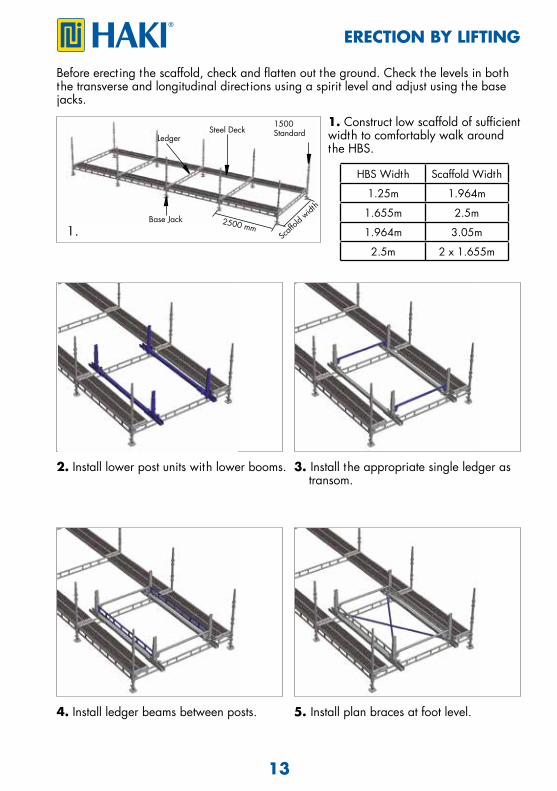
ERECTION BY LIFTING
1. Construct low scaffold of sufficient width to comfortably walk around the HBS.
Before erect ing the scaffold, check and flatten out the ground. Check the levels in both the transverse and longitudinal direct ions using a spirit level and adjust using the base jacks.
HBS Width Scaffold Width
1.25m 1.964m
1.655m 2.5m
1.964m 3.05m
2.5m 2 x 1.655m
2. Install lower post units with lower booms.
2500 mm
Ledger
Base Jack
Steel Deck1500 Standard
Scaff
old w
idth
4. Install ledger beams between posts.
3. Install the appropriate single ledger as transom.
5. Install plan braces at foot level.

14
7.
8.
6.
9.
11.10.
ERECTION BY LIFTING
6. Install a transom on the bottom chord ofthe ledger (transom is not necessary, if ALdecks are used on the HBS).
8. Install the central sect ions of the postsand secure them with bolts and nuts(hand t ighten only).
10. Install the upper post units and securethem with bolts and nuts (hand t ightenonly).
7. Install the decks.
9. Install side handrail units and aguardrail frame at front of assembly.
11. Install guardrail frames around all 4sides of the HBS bay.

15
12. 13.
15.14.
16. 17.
ERECTION BY LIFTING
12. Install the erect ion platforms to the top of the handrails, and access to the temporary platform.
13. Install upper single ledgers between upper post units.
14. Install upper booms. 15. Install upper plan braces.
16. Install HBS diagonal braces, 2 per side (hand t ighten only).
17. Remove all the 1655mm guardrail frames and all the erect ion platforms.Use the removed components to erect the next bay of the HBS.

16
19.
20.
18.
ERECTION BY LIFTING
18. Repeat stages 2-17 forremaining HBS bays.Once bridge has reached required length t ighten all fixings (handrails, bracing, vert ical posts).
19. In accordance with Lift ingPlan, attach slings and lift toallocated posit ion on tripodlegs.
20. Fit clamps to tripod headadapter and remove lift ingequipment.NOTE: Clamps should not be OVERTIGHTENED. Bridge should be permitted to ‘slide’ in its longitudinal direct ion. End fixing details on page # in this manual.
1b.
1a.
3.
2.
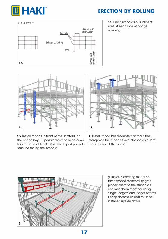
1b. Install tripods in front of the scaffold (on the bridge bay). Tripods below the head adap-ters must be at least 1.0m. The Tripod pockets must be facing the scaffold.
2. Install tripod head adapters without theclamps on the tripods. Save clamps on a safeplace to install them last.
1a. Erect scaffolds of sufficient area at each side of bridge opening.
3. Install 6 erecting rollers on the exposed standard spigots, pinned them to the standards and lace them together using single ledgers and ledger beams. Ledger beams (in red) must be installed upside down.
Bridge opening
TripodsBay to suit stair width
PLANLAYOUT
Bay
to s
uit
brid
ge w
idth
770
17
ERECTION BY ROLLING

4.
5.
5. From the walkboards, assemblethe trolley on 750 Beams. Securethe trolley to the main scaffold usingratchet straps.
DON’T USE PINS AS THIS STOPS THE WHEELS ON ROLL-OUT.
4. Install HAKITEC 750 beams 1m below the scaffold top lift. Lace and brace themtogether with the aid of walkboards. End baysmust be cross-braced. On top chord of thebeams, install the straight connector and T&F.
HBS Width 750 Beams Width
1.25m 1.655m
1.655m 2.5m
1.964m 2.5m
HBS Width Trolley Width
1.25m 1.655m
1.655m 2.5m
1.964m 2.5m
BRS (4 off)
1.0m Standard (4 off)1.25m Ledger Beam (4 off)
450mm
2.5m Ledger Beam (4 off)
1.964m Diagonal Brace (2 off)
Adj. Base Jack (4 off)
750 Adj. Rolling Roof Wheel (4 off)
T&F (2 off)
18
ERECTION BY ROLLING

6. 7.
8.
9.
6. Install the first two HBS bays on the rollers,repeat steps 2 to 6 of the ‘’ erection by lifting’’ procedure in this manual (pg.13&14). Secureframework to erecting platform using ratchetstraps.
7. Repeat steps 7 to 17 of the‘’erection by lifting’’ procedure in this ma-nual (pg.14&15). Do not dismantle the frontguardrail frames.
8. Release ratchet straps and roll bridge sec-tion forward using the lower booms. Roll thebridge out until the third plate of the ledger beam on the side is above the ledger beamson the trolley. Secure bridge bay to trolley using ratchet straps.
9. Complete the third bay and repeat the process for any other bays until reach the requiredlength. Use ’spare’ lower booms to move the bridge to its final position. Re-strap the booms atfar-end.
19
ERECTION BY ROLLING

1. 2.
3. 4.
Lowering Bridge to its final position.The following procedure should be performed from the safety of the main scaffold.
1. Install the jack brackets on the headadaptor. Tighten the couplers to secure.Install the bottle jacks on the jack brackets.Trolley omitted for clarity.
2. Release ratchet straps from the trolley and bridge bay. Using the bottle jacks, raiseboth sides of the bridge in unison by 30mm.Trolley omitted for clarity.
3. Lower the front trolley jacks and push thetrolley away.
4. Using the bottle jacks, lower both sidesof this end of the bridge into final posi-tion at the same time. Fit clamps to tripodhead adapter. NOTE: Clamps should not beOVERTIGHTENED.
5. Remove end 1.655m guardrail frames from bridge. Dismantle the trolley from the safety of the access platform. Repeat steps 1,2 and 4 in this procedure(pg.20) on opposite side of thebridge removing the lower booms at this side. Once bridge is on its final position, tighten all fixings (handrails, diagonal bracing, and vertical posts).End fixing, connection to end structure, and bracing details on page 22 and 23 in this manual.
20
ERECTION BY ROLLING

2.
3.
1.
4.
1. Install U-Track Units in the end bays.
3. Install Cladding Panels between Tracks.
2. Install H-Track Units in the middle bays.
4. Secure all the Tracks on place installing aTrack Clamp per Track Unit.
21
CLADDING ERECTION
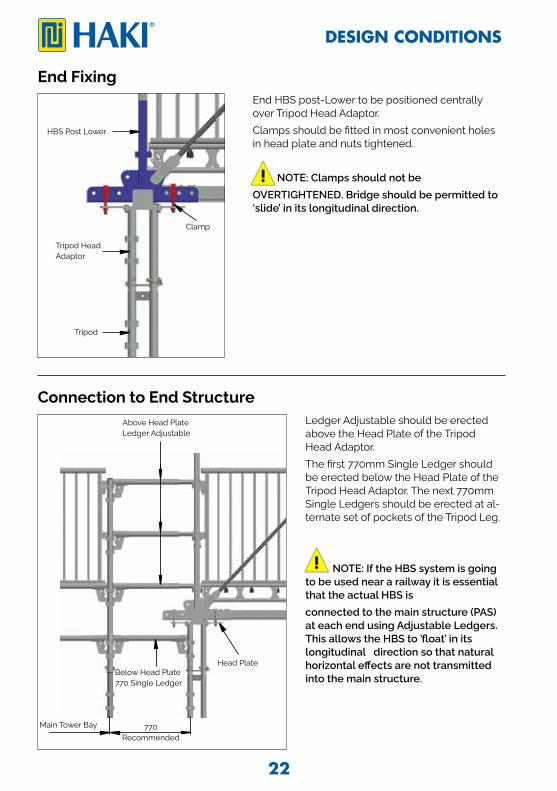
End Fixing
HBS Post Lower
End HBS post-Lower to be positioned centrally over Tripod Head Adaptor.Clamps should be fitted in most convenient holes in head plate and nuts tightened.
NOTE: Clamps should not be OVERTIGHTENED. Bridge should be permitted to ‘slide’ in its longitudinal direction.
Connection to End StructureLedger Adjustable should be erected above the Head Plate of the Tripod Head Adaptor.The first 770mm Single Ledger should be erected below the Head Plate of the Tripod Head Adaptor. The next 770mm Single Ledgers should be erected at al-ternate set of pockets of the Tripod Leg.
NOTE: If the HBS system is going to be used near a railway it is essential that the actual HBS isconnected to the main structure (PAS) at each end using Adjustable Ledgers. This allows the HBS to ’float’ in its longitudinal direction so that natural horizontal effects are not transmitted into the main structure.
Tripod Head Adaptor
Clamp
Tripod
Above Head PlateLedger Adjustable
Below Head Plate770 Single Ledger
Head Plate
770Recommended
Main Tower Bay
22
DESIGN CONDITIONS

BracingAt ends of bridge, Sway Braces fitted to Upper Posts using integral bolts & nuts and to adja-cent scaffold structure at lower ends using load bearing couplers to provide lateral stability.
Sway BracesSway Braces
Sway Braces
23
DESIGN CONDITIONS

Instruction for dismantling1. Dismantle the tower in the reverse order from the erection sequence.2. Do not throw or drop materials to the ground. This may damage the material or
cause personal injury. The material must be lowered down to the ground by means of ropes or slings or passed down by hand.
3. Always observe and comply with the regulations published by the lical authoritiesconcerned.4. Reference should also be made to the section ”Information on safety when erecting
and dismantling” in this manual.
24
DISMANTLING

27
Notes

Health and Safety at Work Act, 1974
Experience With over 60 years experience to call on, HAKI has gained a leading reputat ion in its field. With its own R & D and manufacturing facilit ies, the company now operates throughout Europe and its equipment is in use worldwide. With all products designed and manufactured to ISO 9001:2008, and a comprehensive training and supportinfrastructure, you can rely on HAKI for support.
Training The Company´s dedicated Training Centre is equipped with the full range of HAKI products where a comprehensive choice of courses is offered. With the benefit of this training, all users of HAKI products can be assured that the equipment is being employed safely and effect ively.
Support From computerised est imating facilit ies to on site assessment and project back up, HAKI is with its customers every step of the way. Working with HAKI means far more than just proven equipment, it means working with people who understand the scaffolding industry. Whatever the project, the company is committed to ensuring every user enjoys the full benefits associated with the use of HAKI - maximising the savings, profitability, and above all, SAFETY.
HAKI equipment is designed to meet the requirements of the above Act, Sect ion 6.It is also the customer´s responsibility to comply with the requirements of this Act, part icularly to use the equipment in accordance with current codes of pract ice and in ensuring that components are in good working condit ion prior to each use.We are able to provide assistance and advice on matters relat ing to safe and proper use of HAKI equipment.
HAKI AB • SE-289 72 Sibbhult, Sweden • Tel +46 44 494 00 • [email protected] www.HAKI.com ©
HA
KI IN
T 20
21 0
4 P
0002
00