Embed Size (px)
Citation preview

ID UM.L82345.2012
LONIX LTD Teollisuuskatu 33 Tel. +358 9 349 9853 VAT 1043054-9
www.lonix.com FI-00510 Helsinki, Finland Fax +358 9 349 9863 Trade Reg.No. 678.356
User Manual
COBA Editor

User Manual 2 (18)
COBA Editor
LONIX LTD Teollisuuskatu 33 Tel. +358 9 349 9853 VAT 1043054-9
www.lonix.com FI-00510 Helsinki, Finland Fax +358 9 349 9863 Trade Reg.No. 678.356
Index
COBA Editor 4
1. General Information ...................................................................................................................... 5
2. New Project Creation .................................................................................................................... 6
2.1 Getting Started ................................................................................................................................ 6
2.2 Creating the Project Structure ......................................................................................................... 7
2.3 Adding Control Groups .................................................................................................................... 7
3. Graphics Creation .......................................................................................................................11
3.1 Tools for Editing Graphics .............................................................................................................11
3.2 Adding Images ..............................................................................................................................11
3.3 Adding Labels ................................................................................................................................13
3.4 Adding Links ..................................................................................................................................13
4. Control Group Templates ...........................................................................................................15
5. Exporting the User Interface to COBA Server ..........................................................................18

User Manual 3 (18)
COBA Editor
LONIX LTD Teollisuuskatu 33 Tel. +358 9 349 9853 VAT 1043054-9
www.lonix.com FI-00510 Helsinki, Finland Fax +358 9 349 9863 Trade Reg.No. 678.356
Introduction This document describes functionality of the COBA Editor application. COBA Editor is a software tool for implementation of graphical User Interfaces for COBA connected systems. COBA Editor includes a selection of libraries and templates for graphics creation to different systems. COBA Editor supports creation of new templates as well. The model of the building, its systems and devices is created using the COBA Editor. Features of COBA Editor include the following: - Drag & drop and copy-paste functionality - Templates for user interface creation (standard, user, project) - Importing floor plans from image files (jpg, gif, png) - Using defined areas in pictures as links - Modeling support This document is meant primarily for system integrators and other automation system professionals.

User Manual 4 (18)
COBA Editor
LONIX LTD Teollisuuskatu 33 Tel. +358 9 349 9853 VAT 1043054-9
www.lonix.com FI-00510 Helsinki, Finland Fax +358 9 349 9863 Trade Reg.No. 678.356
Functionality Description
� General
� New Project Creation
� Graphics Creation
� Control Group Templates
� Exporting the User Interface
COBA Editor

User Manual 5 (18)
COBA Editor
LONIX LTD Teollisuuskatu 33 Tel. +358 9 349 9853 VAT 1043054-9
www.lonix.com FI-00510 Helsinki, Finland Fax +358 9 349 9863 Trade Reg.No. 678.356
1. General Information
COBA Editor is a software tool for implementation of graphical User Interfaces for COBA connected systems. COBA Editor includes a selection of libraries and templates for graphics creation to different systems. COBA Editor supports creation of new templates as well. The model of the building, its systems and devices is created using the COBA Editor. Features of COBA Editor include the following:
� Drag & drop and copy-paste functionality
� Templates for user interface creation (standard, user, project)
� Importing floor plans from image files (jpg, gif, png)
� Using defined areas in pictures as links
� Modeling support
The following figure illustrates the layout of COBA Editor.
User Manual 6 (18)
COBA Editor
LONIX LTD Teollisuuskatu 33 Tel. +358 9 349 9853 VAT 1043054-9
www.lonix.com FI-00510 Helsinki, Finland Fax +358 9 349 9863 Trade Reg.No. 678.356
2. New Project Creation
2.1 Getting Started
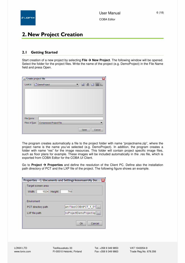
Start creation of a new project by selecting File ���� New Project. The following window will be opened. Select the folder for the project files. Write the name of the project (e.g. DemoProject) in the File Name field and press Open.
The program creates automatically a file to the project folder with name “projectname.zip”, where the project name is the name you’ve selected (e.g. DemoProject). In addition, the program creates a folder with name “res” for the image resources. This folder will contain project specific image files, such as floor plans for example. These images will be included automatically in the .res file, which is exported from COBA Editor for the COBA UI Client. Go to Project ���� Properties and define the resolution of the Client PC. Define also the installation path directory of PCT and the LXP file of the project. The following figure shows an example.

User Manual 7 (18)
COBA Editor
LONIX LTD Teollisuuskatu 33 Tel. +358 9 349 9853 VAT 1043054-9
www.lonix.com FI-00510 Helsinki, Finland Fax +358 9 349 9863 Trade Reg.No. 678.356
2.2 Creating the Project Structure
The project structure (Building Model and Control Systems) are created with COBA Editor. You can use the same structure as in Lonix PCT project, but sometimes you may want to make them look a bit different for simplicity. An estate can have many buildings, a building can have many building parts, and a building part can have many building parts and spaces. Control Systems can only be placed under a building object. The following figure illustrates a Building Model. You can add buildings, building parts and spaces with the Building Model by right-clicking on an object.
When viewed in the COBA Client software, only those Control Systems and Building Parts with any graphics added to them or a system under them are shown.
2.3 Adding Control Groups
It is recommended to create all new Control Groups under the corresponding Control Systems. If needed, you can then later create copies of the Control Groups and paste them under estates, buildings, building parts and spaces. Right-click on a Control System and select “Add Control Group”. A dialog is opened to see all available Control Groups, grouped in libraries (e.g. dedicated libraries for Lonix Automation and Lonix Security Control Groups). Double-click the library tree to see its contents. Depending on your project, you may need Control Groups from all libraries or from a single library only.

User Manual 8 (18)
COBA Editor
LONIX LTD Teollisuuskatu 33 Tel. +358 9 349 9853 VAT 1043054-9
www.lonix.com FI-00510 Helsinki, Finland Fax +358 9 349 9863 Trade Reg.No. 678.356
Select an appropriate Control Group as illustrated in the following figure, give it a descriptive name and click OK.
When you have added the Control Group you need to define its properties to let COBA Server know which I/O-object it is mapped to, and which driver and NID pipe should be used. Otherwise COBA cannot communicate with the I/O-object. The following figure shows definition of Control Group properties.

User Manual 9 (18)
COBA Editor
LONIX LTD Teollisuuskatu 33 Tel. +358 9 349 9853 VAT 1043054-9
www.lonix.com FI-00510 Helsinki, Finland Fax +358 9 349 9863 Trade Reg.No. 678.356
Expand the Control Group by clicking on the + sign in front of it to get a view of all the Information Points the Control Group has. Select one of them to see its properties. By default, most of the Control Groups use com.lonix.LonixMultiDriver. This is used in conjunction with COBA HMINid Service and a LON network card. When using a LNI and COBA LNI Service, the driver class should be com.lonix.LonixMultiDriverLNI. Define the NID Pipe accordingly. The above parameters (Driver Class and NID Pipe) can also be set direct from the project tree by right-clicking on the Information Point, Control Group or the Control System level where it is contained. When you select “Apply changes to subnodes” as shown in the following dialog, the same settings are applied to all objects below the selected level. For example, you can select the settings from Control System level to Information Points included in the Control System.
To map an Information Point of the Control Group to an I/O-object, click on the Value field of the I/O-Object property. A small grey button will appear to its right side. Click the small button to open a dialog that allows you to select the appropriate I/O-Object from a list. The list will show all I/O-objects of the correct type that exist in the LXP file of the project. If the project’s LXP file is not defined in the COBA Editor properties, then the mapping cannot be done. Also, if any changes are made to the LXP, then COBA Editor needs to load the file again. This is done when the COBA Editor project is opened. When an Information Point is mapped to an I/O-object successfully, its name will be shown in green color. The following figure illustrates mapping of a Control Group to an I/O-object.
User Manual 10 (18)
COBA Editor
LONIX LTD Teollisuuskatu 33 Tel. +358 9 349 9853 VAT 1043054-9
www.lonix.com FI-00510 Helsinki, Finland Fax +358 9 349 9863 Trade Reg.No. 678.356
An Information Point consists of several Data Points, which are used for reading and writing data from the COBA Server. Each Data Point is mapped to an input, output or configuration network variable visible at its Address property. In general, the address does not need to be changed. There is sometimes a need to change the unit or range of a measurement, for example. The unit of measurement is defined with the Type ID property, the measurement range with the OEM Value Conversion property. To change the type ID to a more suitable unit, you can check the file coba_types.xml, located in <COBA installation folder>\config\ctrls for available measurement units. This file can be modified by editing any of the existing type IDs that are not needed in the project. To change the range of a measurement in COBA, define a value for the OEM Value Conversion property. Note that this only affects how the measurement is displayed in COBA UI, not the actual measurement (AI-object).
Example:
A differential pressure transducer with a range of 0 to 500 Pa is connected to an AI-object in a Lonix Controller. The AI-object’s nvo_AI_Sensor outputs a value of 0 to 100 according to the active 0-10V signal from the transducer. For example, when the pressure difference is 300 Pa, the value of nvo_AI_Sensor of the AI-object is 60. Without any OEM Value Conversion the reading in COBA UI would also be 60. But if a value of 5 is defined in the OEM Value Conversion property of the outMeasure Data Point, COBA will multiply the value of nvo_AI_Sensor with 5, thus giving a reading of 300 Pa (60 * 5 = 300) in COBA User Interface. If the AI-object is also an alarming point with HiHi-, Hi-, Lo- and LoLo-alarm limits and these may be changed through a dialog in COBA UI, then also the corresponding Data Points (HiHi-Level Alarm, Hi-Level Alarm, Lo-Level Alarm and LoLo-Level Alarm) need to have exactly the same OEM Value Conversion property as the outMeasure Data Point. When inputting new alarm limits, COBA will use the value to divide the input, e.g. if a user inputs a new alarm limit of 100 Pa, then it will be 20% of the measurement range and the corresponding configuration variable will receive an input of 20 (100 / 5 = 20).

User Manual 11 (18)
COBA Editor
LONIX LTD Teollisuuskatu 33 Tel. +358 9 349 9853 VAT 1043054-9
www.lonix.com FI-00510 Helsinki, Finland Fax +358 9 349 9863 Trade Reg.No. 678.356
3. Graphics Creation
3.1 Tools for Editing Graphics
The COBA Editor includes the following tools for editing the graphics.
Tool Description
Selection Tool for selecting and moving objects.
Image Tool for creating images for the Building Model or Template. The Editor supports gif, jpg and png image formats. The Properties editor includes attributes like Scalable and Tiled, which can be applied to the images for effects accordingly.
Changeable Image Tool with which an image can be created, which changes with the value of a DataPoint. The Properties editor includes the same attributes as the Image tool.
Label Tool for writing texts into the Drawing area or Template. The text itself, its font and the borders are handled by the Properties editor.
Area Selection Tool for linking buildings, spaces or rooms.
Link Tool for creating links between building parts and control systems.
File Reference Tool for making links to external documents.
The tools are accessed by clicking the icons located in the right-hand side toolbar in the bottom of the page. Please note that Changeable Image Tool is only applicable when creating Control Group Templates.
3.2 Adding Images
Select an object in the tree structure of the Building Model where the image will be added. The building model object with the currently active view will be displayed with a blue background. Then select the Image Tool and press the left mouse button in the drawing area. Define the size of the image area by dragging the mouse downwards to the right (the image size can be modified later). A window pops up where you can choose the image file under the Predefined images or Project images tabs. If you want to use your own graphics (e.g. floor plans), then use the import functionality in Project images tab. The files you import are stored under “res” folder inside the project file directory and can be later accessed through the Project images tab.

User Manual 12 (18)
COBA Editor
LONIX LTD Teollisuuskatu 33 Tel. +358 9 349 9853 VAT 1043054-9
www.lonix.com FI-00510 Helsinki, Finland Fax +358 9 349 9863 Trade Reg.No. 678.356
The following figure shows an example about adding graphics.
The image appears in the drawing area in its actual size, but it can be resized at any time as follows: Select the image with the Object Selector Tool in the lower toolbar, and tag the Scalable attribute in the Properties editor. Now resize the image by dragging the green frame or changing the values of the width and height in the Properties editor.
User Manual 13 (18)
COBA Editor
LONIX LTD Teollisuuskatu 33 Tel. +358 9 349 9853 VAT 1043054-9
www.lonix.com FI-00510 Helsinki, Finland Fax +358 9 349 9863 Trade Reg.No. 678.356
3.3 Adding Labels
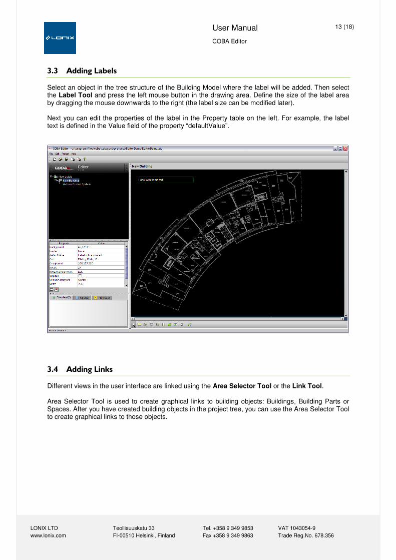
Select an object in the tree structure of the Building Model where the label will be added. Then select the Label Tool and press the left mouse button in the drawing area. Define the size of the label area by dragging the mouse downwards to the right (the label size can be modified later). Next you can edit the properties of the label in the Property table on the left. For example, the label text is defined in the Value field of the property “defaultValue”.
3.4 Adding Links
Different views in the user interface are linked using the Area Selector Tool or the Link Tool. Area Selector Tool is used to create graphical links to building objects: Buildings, Building Parts or Spaces. After you have created building objects in the project tree, you can use the Area Selector Tool to create graphical links to those objects.

User Manual 14 (18)
COBA Editor
LONIX LTD Teollisuuskatu 33 Tel. +358 9 349 9853 VAT 1043054-9
www.lonix.com FI-00510 Helsinki, Finland Fax +358 9 349 9863 Trade Reg.No. 678.356
Using the Area Selector Tool:
Select Area Selector and input the area by clicking the mouse in each corner. Close the area by selecting the first point again. The area turns green. Click the area with the right mouse button to define the target of the link. The target appears in the image when you click on another tool or another part of the drawing area.
You can change the borders of the area at any time with the Area Selector. Select the tool, and pick any corner to drag it into the new location. You can also change the target of the link at any stage.
Using the Link Tool:
With Link Tool you can create labels that can be clicked in COBA UI to open a different view. Links are done in exactly the same way as labels (see: Adding Labels), but after defining the size of the link label, a dialog with the building model will appear for selecting the link target. The target is selected by clicking the target object in the tree and then OK. If you want to have a link on a picture, for example, then first add the picture, and then place a non-opaque link with no text on it.

User Manual 15 (18)
COBA Editor
LONIX LTD Teollisuuskatu 33 Tel. +358 9 349 9853 VAT 1043054-9
www.lonix.com FI-00510 Helsinki, Finland Fax +358 9 349 9863 Trade Reg.No. 678.356
4. Control Group Templates
Normally a Control Group is added into a view through the Template Library. For new kinds of Control Groups also new Templates have to be created. The new template is saved, and will appear in the User or Project Template Library. User Template Library includes templates that can be used in all COBA Editor projects. Project Template Library templates can only be used in that particular project.
Example 1:
Select a Control Group in a Control System and drag it to the graphics area. A temperature measurement Control Group is used in this example. If the active view is any Building Model object except the Control System the Control Group resides in, a reference of the Control Group is created under the Building Model object (Control Group references have their name in cursive and none of its properties can be changed). Click the right mouse button on top of the object in the drawing area, and press Edit. This will open a new view that is for that particular Control Group only. The Label Tool allows you to add a text field. Press Label Tool button and drag the left mouse button in the drawing window to give the size of the label.
You can write static text (e.g. 1st Floor), or text changing with a Data Point value, e.g. a measurement. A right click gives you a pop-up for the selection of the source Data Point, e.g. temperature measurement. Write the text of the label into the DefaultValue field of Label Properties. The Background color of a label can be changed only if opaque is tagged, or a border is selected. You can change the shape of the border with the options empty, etched, lower, raised or line. Font opens a font selection dialog, and Foreground changes the color of the font.

User Manual 16 (18)
COBA Editor
LONIX LTD Teollisuuskatu 33 Tel. +358 9 349 9853 VAT 1043054-9
www.lonix.com FI-00510 Helsinki, Finland Fax +358 9 349 9863 Trade Reg.No. 678.356
Height and Width values indicate the limits of the Control Group, i.e. size of the active area of the object when the mouse is dragged on top of the object. The attributes can be changed either in the Properties editor (press Enter for the values to update), or by dragging the borders of the label. HorizontalAligment and verticalAligment change the position of the text within label. X and Y values indicate the position of the Control Group in the drawing area. The position can be altered also by dragging the object. Press the Image Tool button to add an image into the Control Group. The functionality of the image tool is all available while editing the template. Place the label and the image in the upper left corner of the drawing area and go back to the active view by clicking on the appropriate building model object.
The Control Group with the label and the picture is now visible on the active view. When you now click the Control Group you can adjust its borders. You can also define a dialog for the Control Group by defining the dialog name in the properties of the Control Group. Save the template created for a Control Group by clicking the right mouse button in the drawing area and selecting Save as template ���� OK. The template is saved to either user templates or project templates.

User Manual 17 (18)
COBA Editor
LONIX LTD Teollisuuskatu 33 Tel. +358 9 349 9853 VAT 1043054-9
www.lonix.com FI-00510 Helsinki, Finland Fax +358 9 349 9863 Trade Reg.No. 678.356
Example 2:
For objects with ON and OFF states it is possible to define two pictures that change according to the state. Drag and drop an indication object (Generic Indication Control Group used in this example) on the view, right-click on it and select Edit. Select the Changeable Image Tool for an image displaying two states (ON/OFF). Drag the mouse in the drawing area to define the size, and on releasing the mouse button a selection window pops up to give the source data (state) which selects the displayed image.
In the Property-section, define a default value (ON or OFF) to define which image is shown in offline mode. Then click on the imageMap property to define the two images.

User Manual 18 (18)
COBA Editor
LONIX LTD Teollisuuskatu 33 Tel. +358 9 349 9853 VAT 1043054-9
www.lonix.com FI-00510 Helsinki, Finland Fax +358 9 349 9863 Trade Reg.No. 678.356
5. Exporting the User Interface to COBA Server
The COBA Server uses an XML and a RES file to display the views of a project created in COBA Editor. The files are created with the command Project ���� Export UI Resource File. Browse for the directory where you want to save the RES file, and type the name of the file into the File Name field. The XML (ui.xml) file will be generated automatically in the same folder. As the Control Groups and the Building Model are created with COBA Editor, also CobaControl.xml and CobaEstate.xml files need to be generated. Selecting Project ���� Export COBA XML will generate the two files in the COBA Editor project folder. To test the generated user interface in offline mode you can copy the RES file in <COBA UI Client installation folder>\configFiles folder. Then modify the settings.xml file located in the same folder and change the RES file name in the following to match the project file name:
<Property> <Name>configFile</Name> <Value>DemoProject.res</Value> </Property>
You can then start COBA UI Client in OFFLINE-MODE to preview the user interface. For online mode to work COBA Server needs to be installed. The file locations are as follows:
� Copy CobaControl.xml and CobaEstate.xml into <COBA installation folder>\config\ctrls
directory.
� Copy the RES file to <COBA installation folder>\profiles\Default directory.
� Rename the RES file to Default.res.