Embed Size (px)
Citation preview
i
USE OF PHOTOVOLTAIC SYSTEM FOR STANDBY OPERATION OF A PETROL STATION
Case study National Oil Petrol Station at Nairobi West
By
OWINY, BERNARD OWUOR
PROJECT REPORT SUBMITTED IN PARTIAL FULFILLMENT FOR
POSTGRADUATE DIPLOMA IN ENERGY MANAGEMENT
OF THE UNIVERSITY OF NAIROBI
UNIVERSITY OF NAIROBI
APRIL 2014
i
DECLARATION
STUDENT DECLARATION
This project is my original work and has not been presented for a degree/diploma in any
other university. No part of this project may be produced without the prior permission of
the author/University of Nairobi.
Signature………………………………………………………..
Date………………………………………………………………..
OWINY, BERNARD OWUOR F52/83473/12
SUPERVISORS` DECLARATION
I confirm that the above student carried out this research under my supervision as
University supervisor.
Signature…………………………………………………..
Date………………………………………………………….
Prof .J . A .Nyangaya
( Department of Mechanical & Manufacturing Engineering, University of Nairobi)

ii
ACKNOWLEDGEMENT
I do give thanks to God who has made me reach this far. My appreciation goes to my
supervisor Prof. J .A .Nyangaya for the many hours he spent in guiding and suggesting new
approaches, correcting and final editing of the entire research project report. My gratitude
also goes to Engineer Charles Rangara for the generous technical support and groundwork
offered in coming up with the project.
I would like to thank National Oil Corporation of Kenya through Engineer Stephen Buku for
having given me access to their petrol station to use as a case study.

iii
DEDICATION
I dedicate this Research Project to my wife Evelyn , Sons Belyn Gweth and Benjamin Owiny
,May you live longto change this Planet and make it a better place than you found it.

iv
ABSTRACT
The objective of the study was to compare the cost of using a standby diesel engine
generator with that of a photovoltaic system to operate the equipments at a petrol station
during a power blackout .
The total power consumption for operation of the petrol station was estimated from the
rating of the installed equipments and subsequently a photovoltaic system of equivalent
output was designed . The advantages and disadvantages of the two systems were
contrasted.
The photovoltaic system was found to be viable for the petrol station in spite of a high
initial cost. It has the advantagesof low maintenance cost, clean renewable energy and is
noise free.
v
TABLE OF CONTENTS
Declaration ............................................................................................................................ i
Acknowledgement ............................................................................................................... ii
Dedication ........................................................................................................................... iii
Abstract ............................................................................................................................... iv
Table of contents ................................................................................................................. v
List of Tables ..................................................................................................................... viii
List of Figures .................................................................................................................... viii
CHAPTER ONE ......................................................................................................................1
1.0 Background ....................................................................................................................1
1.1 Grid and Stand Alone solar power Systems ..................................................................2
1.2 National Oil Petrol Station .............................................................................................3
1.3 Rationale for the Study ................................................................................................5
1.4 Objective of Study ..........................................................................................................6
1.5 Limitations of Study .......................................................................................................6
CHAPTER TWO .....................................................................................................................7
vi
LITERATURE REVIEW ............................................................................................................7
2.1 Energy Consumption In Kenya .......................................................................................7
2.2 Operation of machines in the Petrol Station ................................................................8
2.2.1 The Fuel Storage Tank .................................................................................................8
2.2.2 Fuel Dispenser .............................................................................................................8
2.2.3 Air Compressor ...........................................................................................................9
2.2.4 DieselStandby Generator ......................................................................................... 12
2.3 Photovoltaic energy Science ....................................................................................... 12
2.3.1 Solar System ............................................................................................................. 13
2.3.2 Photovoltaic Solar Module ...................................................................................... 14
2.4 Sun Characteristics ...................................................................................................... 15
CHAPTER THREE ................................................................................................................ 17
METHODOLOGY ................................................................................................................ 17
3.1 Data Collection Methods ............................................................................................ 17
3.2 Kenya Powerand Lighting electricity bill ..................................................................... 20
3.3 Data Analysis ............................................................................................................... 22
CHAPTER FOUR ................................................................................................................. 23

vii
DATA ANALYSIS AND DISCUSSION .................................................................................... 23
4.1 Site Survey and Discussion .......................................................................................... 23
4.1.1 Fuel Consumption Cost ............................................................................................ 24
4.1.2 Maintenance Cost of the Generator ........................................................................ 25
4.2 Photovoltaic System ................................................................................................... 26
4.2.1 Sizing of Photovoltaic Array ..................................................................................... 27
4.2.2 Inverter………………………………………………………………………………………………………………..28
CHAPTER FIVE ................................................................................................................... 30
5.1 Solar energy as an alternative source of Power……………………………………………………..30
5.2Conclusion .................................................................................................................... 30
5.3 Recommendation ........................................................................................................ 32
REFERENCES ...................................................................................................................... 33

viii
List of Tables
1.1 Equipments at a Filling Station ......................................................................................5
2.2 Difference between Reciprocating and Rotary Compressors .................................... 10
3.3Rate of fuel consumption of generator ....................................................................... 18
3.4 Duration of operation of generator………………………………………………………………………..19
3.5Equipments Consuming Power at filling Station ........................................................ 20
3.6 Kenya Power and Lighting electricity bill .................................................................... 21
4.7 Power demand during a power blackout ................................................................... 25
4.8 Generator Spares and cost of oil ............................................................................... 26
4.9 PhotovoltaicSystem Design Template ........................................................................ 30
List of Figures
1.1 Nairobi West Petrol Station ..........................................................................................4
2.2 Standby Generator ................................................................................................ 11
2.3 Solar Energy Emission Path .................................................................................. 13
2.4 Solar Module ......................................................................................................... 14

1
CHAPTER ONE
1.0 BACKGROUND
Kenya has an installed Energy capacity of 1.48GW. Whilst about 57 % is hydro power, about
32% is thermal and the rest comprises geothermal and emergency thermal power. Solar
photovoltaic and wind power play a minor role contributing less than 1%. However
hydropower has ranged from 38-76% of the generation mix due to poor rainfall.( Kenya
Energy Situation , 2013)
The hydropower is mainly affected when the level of water in dams start falling due to lack
of enough rain which results in power rationing. The generators burning fossil fuels come
into operation to salvage the deficiency of power. This is a very expensive source for the
cost of fuel is high.
The rate of electricity consumption at peak hours is higher than the generation, hence some
loads have to be switched OFF especially during the day in some residential areas in order
to supply the most busy areas like industries and some offices
This fluctuation causes power blackouts in some areas especially during the day.
Businesses like petrol stations experiencing power blackoutshave installed standby
generators to sustain the load during power blackouts.
Photovoltaic system is a method of generating electrical power by converting solar
radiation into direct current electricity using semiconductors that exhibits the photovoltaic
effect. Photovoltaic power generation employs solar panels composed of a number of solar
cells containing photovoltaic material

2
1.1 GRID VERSUS STAND ALONE SOLAR POWER SYSTEM
A grid solar power system is one which is connected to the local utility grid so
that the surplus electricity produced by the solar panels is fed into the grid
system. In a grid connected solar power system when the equipments require
more power than what is supplied by the solar panels , then the difference is
supplied by the utility grid.
In a stand alone solar power system, the solar panels are not connected to the
grid but instead they are used to charge a bank of batteries. The batteries in the
bank store power ( D.C Charge) produced by the solar panels, which is then
converted to A.C Charge and used to power electrical loads especially during
non-daylight hours.
Stand alone solar system are of two types, without batteries and with batteries.
1. The systems without batteries provide power only during a sunny day and
lack power at night or during a bad weather.
2. The system with battery bank provide solar power as long as the battery
charge is above the minimum charge level.
For this study the petrol station is to be designed to use a stand alone solar
power system with batteries, which will be used as a backup system in the
absence of the utility power.

3
1.2 NATIONAL OIL PETROL STATION
The National Oil Corporation of Kenya is a state Co-operation of Kenya by an act of
parliament in 1981 with a mandate of participating in all aspects of the Kenyan
petroleum industry. It is 100% owned by the Kenyan government, the company is
known as National Oil Co-operation of Kenya with main offices located in
Nairobi.The company is involved in upstream activities such as exploration,
geological research and production and in downstream activities such as supplyof
petroleum products, retail networking. National Oil operates 85 service stations
across Kenya.
(National Oil of Kenya, 2012)
The most common fuels sold today are petrol, diesel fuel and kerosene. The filling station
has underground storage tanks for the storing of the different types of fuels sold . Fuel is
usually offloaded from a tanker truck into the storage tanks through a valve, located on the
filling stations perimeter. Fuel from the tanks flows to the dispenser pumps through
underground pipes

4
Nairobi West Petrol Station
Figure 1.1 Nairobi West Petrol Station
The facility chosen for study is located off Muhoho road and GandhiAvenue in
Nairobi west. The petrol station has one overall manager. Operations at the petrol
station are divided into two shifts per day and managed by a supervisor and four
pump attendants. The equipment’s that consume electricity at the site are in Table
1.1

5
Table 1.1Equipments at the Filling Station
Equipments QUANTITY DESCRIPTION
Compressor 1 Atlas Copco- 5.5kW
Generator 1 Massey Fergusion – 30kVA
Diesel Pump 1 Wayne fuel pump- 1.5kW
Petrol Pump 3 Wayne fuel pump-1.5kW
Fridge for colddrinks 1 520W
Security Lights 2 38W
Fluorescent fittings at the
forecourt
6 38W
1.3 RATIONALE FOR THE STUDY
Power outage is mainly due to weather challenges and power rationing during
peakhours when the generated capacity cannot fully supplement the rate of
consumption .In filling stations standby generators are generally arranged tostart
immediately there is an outage of commercial power from the utility
company.The present study is designed to compare the cost of sustaining
operations during outage using a stand alone photovoltaic system instead of a
diesel engine generator.

6
1.4 OBJECTIVES OF STUDY
The specific objectives of the study were
1. Identify the energy consuming units and estimate the total energy
consumption at the petrol station.
2. Estimate the duration of use of generator .
3. Design of photovoltaic systemunit as an option to use of generator
4. Carry out comparative costing of the options.
1.5 Limitations of the Study
The following constraint were experienced during the study,
1. There were missing records like ,records of fuel used to fill the generator and also
records of spares bought and used for generator maintenance.
2. Some important information was not stored at the petrol station but at the
company’s headquarters and could not be accessed. This included the cost of some
electrical equipments .

7
CHAPTER TWO
LITERATURE REVIEW
2.1 Energy consumption in Kenya
Kenya’s electricity mix is dominated by hydro generation cover and this is highly vulnerable
to weather conditions and climate change. The climate conditions of 1998-2000 and 2008-
2009 curtailed hydropower generation and led to severe energy shortage which resulted
into power rationing. Electricity demand in the country is significantly rising mainly due to
the accelerated productive investment and increasing population.
Currently the electricity demand is 1,191MW against an effective installed capacity of
1,429MW under normal hydrology. The peak load is projected to grow to about 2500MW
by 2015 and 15000MW by 2030. To meet this demand, the projected installed
capacityshould increase gradually to 19,169MW by 2030. The use of petroleum for power
generation does not offer a lasting solution due to fluctuations in global market prices of
crude oil and the climate impacts of increased green house gas emission.( KenyaPolicy and
Regulatory Overview, 2012)
To address these challenges the government has formulated strategies whose objectives
are to rapidly expand installed electricity capacity ,expand and upgrade the transmission
and distribution networks and develop renewable energy sources like Solar, geothermal
and wind. Kenya being a tropical country receives sunshine throughout the year hence a
good source of solar radiation is available .

8
2.2 Operation of machines in a petrol station
The operation of some of the main equipments at the petrol station as tabled in table 1.1 is
described as below
2.2.1 The Fuel Storage Tank
The fuel sold at service stations is stored underground in storage tanks. Separate tanks
store different types of fuel like diesel, petroleum and kerosene.
2.2.2 Fuel dispenser
A dispenser is used to pump the fuel from the underground storage tanks.
A modern fuel dispenser is logically divided into two main parts;-
An electronic head containing an embedded computer to control the action of the pump,
drive the pump`s display, and communicate to an indoor sales system.
The mechanical section which in a ` self contained` unit has an electric motor, pumping unit
, meters, pulser and valves to physically pump and control fuel flow.

9
2.2.3 Air Compressor
An Air compressor takes free air into an intake port, and using mechanical means whether
pistons,screws or rotary sliding vanes, pushes that air into a smaller area . The compressor
at the filling station is of 5.5KW and of make Atlas Copco. It is a rotary type compressor
which has a continuous action. As more and more air is pushed into the smaller area the
pressure continues to increase inside the tank. There is a pressure switch that monitors the
air pressure inside the tank. When the air pressure reaches the high pressure level setting of
150bar, the compressor shuts off. When air is used from the tank, the air pressure inside
the tank fall gradually and when it reaches the pressure switch low pressure setting of
80bar, it turns the compressor ON until the pressure inside the tank again reaches the high
set pointand the sequence is repeated again.
Types of compressors
Reciprocating Compressors –use pistons driven by crankshaft. They can be either
stationary or potable , can be single or multi-staged and can be driven by electric motors or
internal combustion engines. Small reciprocating compressors from 5 to 30 horsepower
(hp) are commonly seen in automotive applications and are typically for intermittent duty.
Larger reciprocating compressors well over 1000 hp (750 KW) are commonly found in large
industrial and petroleum applications. Discharge pressures can range from low pressure to
very high pressure (>18000psi or 180MPa). In certain applications such as air compression,
multi-stage double –acting compressors are said to be the most efficient available an are
typically larger and more costly than comparable units.
10
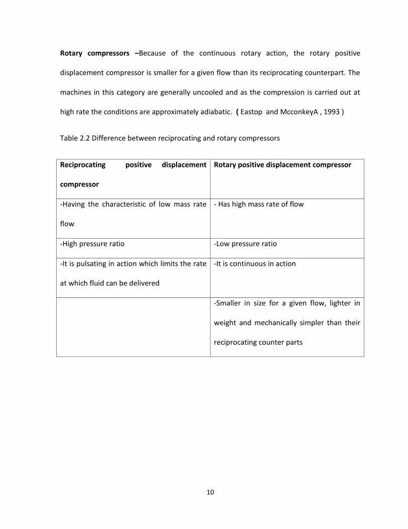
Rotary compressors –Because of the continuous rotary action, the rotary positive
displacement compressor is smaller for a given flow than its reciprocating counterpart. The
machines in this category are generally uncooled and as the compression is carried out at
high rate the conditions are approximately adiabatic. ( Eastop and McconkeyA , 1993 )
Table 2.2 Difference between reciprocating and rotary compressors
Reciprocating positive displacement
compressor
Rotary positive displacement compressor
-Having the characteristic of low mass rate
flow
- Has high mass rate of flow
-High pressure ratio -Low pressure ratio
-It is pulsating in action which limits the rate
at which fluid can be delivered
-It is continuous in action
-Smaller in size for a given flow, lighter in
weight and mechanically simpler than their
reciprocating counter parts
11
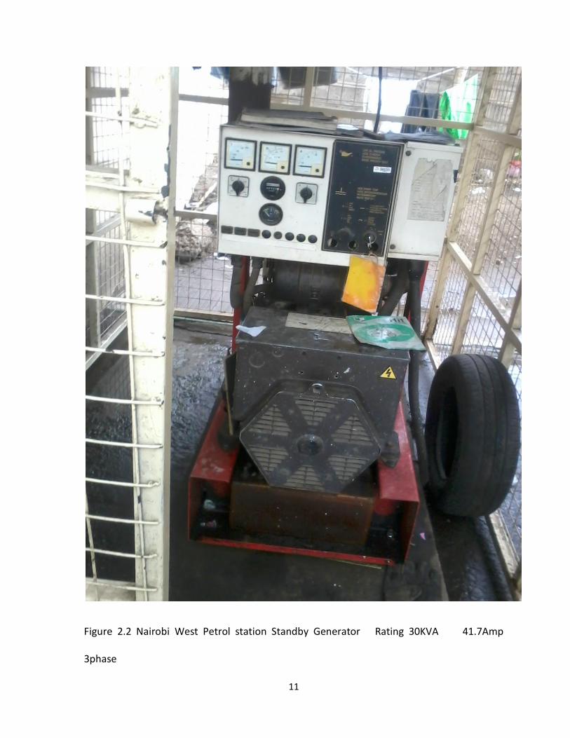
Figure 2.2 Nairobi West Petrol station Standby Generator Rating 30KVA 41.7Amp
3phase

12
2.2.4 DieselStandby Generator
A diesel engine generator is the combination of diesel engine and an electric generator to
generate electric energy .Figure 2.2 shows the standby Generator found at the petrol
station. It has no automatic changeover hence it is switched ON when there is no utility
power and switched OFF when there is utility power.
2.3 Photovoltaic energy science
Solar energy refers to the conversion of solar radiation to practical energy like electricity.
Photovoltaic systems or solar cells are used to turn sunlight directly to electricity . Sunlight
is made up of photons of varying amount of energy depending upon their wavelengths.
When a photon reaches the surface of a solar cell, it may be reflected, it may pass through
or it may be absorbed by the solar cell. The absorbed photon is the only one that can
generate electricity. When absorbed the energy of the photons dislodge an electron from
the solar cell. The electron carrying negative charge travel to the surface of the solar cell
creating imbalance between the front and back surface of the solar cell. The imbalance
becomes the voltage potential similar to the voltage potential between the positive and
negative terminals of the battery. Connecting the two surfaces on load will cause the
electrons to flow creating a current. This is now electricity generated by solar radiation.

13
2.3.1Solar System
Figure2.3 Solar energy emission path
The main components that make up a complete solar system are
Photovoltaic Module – A collection of photovoltaic modules makes a photovoltaic array
which converts sunlight to electricity .It produces DC power which is wired through a charge
controller before it goes on to the battery bank where it is stored
Charge Controller- This is a current regulating device that is placed between the
photovoltaic array and the battery. The primary function of a charge controller in a stand-
alone photovoltaic system is to maintain the battery at the highest possible state of charge
while protecting it from over charge by the arrays and from over discharge by the loads. It
also eliminates any reverse current flow from the batteries back to the solar modules at
night

14
Battery Bank- The battery bank stores the energy produced by the solar array during the
day for use at any time of day or night.
Inverter- The inverter takes the DC energy stored in the battery bank and inverts it to
alternating energy
2.3.2Photovoltaic Solar module
Photovoltaic or PV for short can be thought of as a direct current (DC) generator powered
by the sun. When light photons of sufficient energy strike a solar cell, they knock electrons
free in the silicon crystal structure forcing them through an external circuit (battery or direct
DC load), and then returning them to the other side of the solar cell to start the process all
over again.
Figure 2.4 solar module
( Ubbink East Africa Ltd, “Solar Energy “ )

15
Solar cells- Solar cells use the electronics properties of semi conductor material to convert
sunlight directly into electricity. Major factors which when present in real solar cells affects
theoretical efficiencies include : Reflection losses, incomplete collection of electron hole
pair and voltage factor.( Turner W C & Doty S, 2009 )
2.4Sun characteristics
-Mass= 1.991± 0.002 x 1030 kg
- Radius= 6.960±0.001 x 10⁸m
-Average density= 1.410±0.002 x 10³kg/m3
- Average surface temperature 5762±50K
Solar energy arrives at the edge of the earths` atmosphere, part of this radiation is reflected
back to space, part is absorbed by the atmosphere particles. As a result only about two-
thirds of the sun`s energy reaches the surface of the earth
The amount of solar energy available to collect in a system depends upon whether the
collectors move to follow or partially follow the sun or whether they are fixed. In the case of
fixed collectors, the tilt from horizontal and the orientation of collectors may be significant.
Fixed solar collectors are usually tilted at some angle from the horizontal so as to provide a
maximum amount of total solar energy collected
16
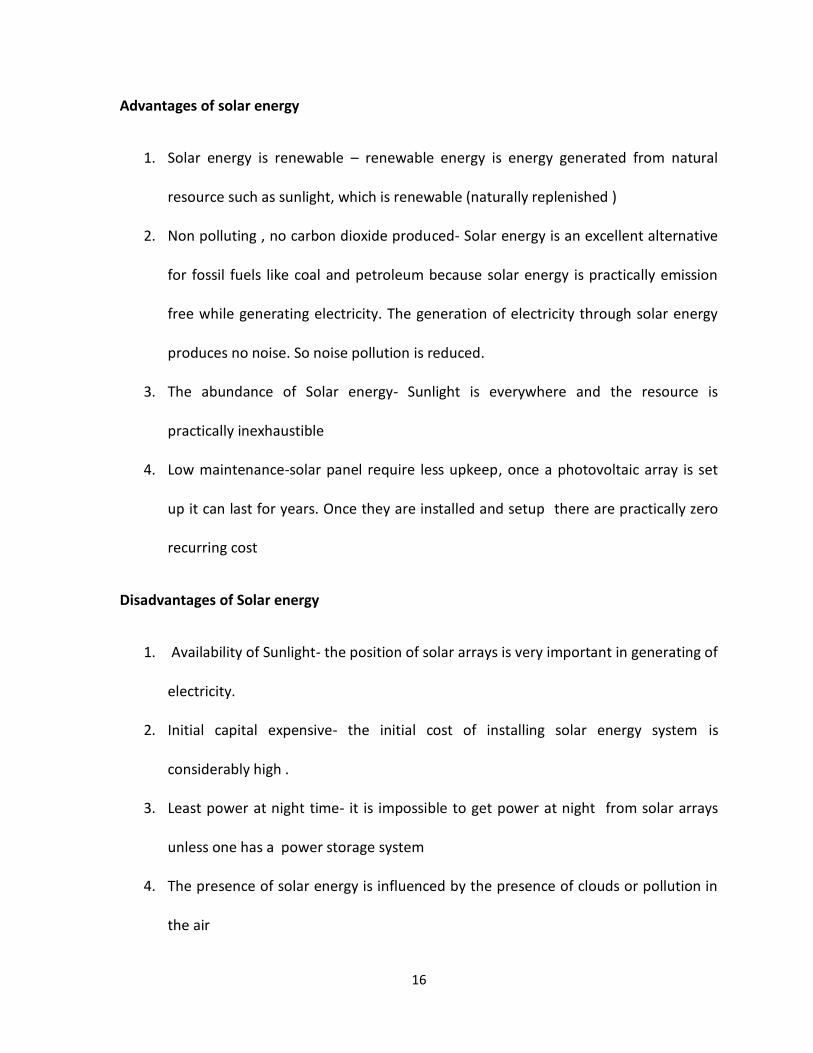
Advantages of solar energy
1. Solar energy is renewable – renewable energy is energy generated from natural
resource such as sunlight, which is renewable (naturally replenished )
2. Non polluting , no carbon dioxide produced- Solar energy is an excellent alternative
for fossil fuels like coal and petroleum because solar energy is practically emission
free while generating electricity. The generation of electricity through solar energy
produces no noise. So noise pollution is reduced.
3. The abundance of Solar energy- Sunlight is everywhere and the resource is
practically inexhaustible
4. Low maintenance-solar panel require less upkeep, once a photovoltaic array is set
up it can last for years. Once they are installed and setup there are practically zero
recurring cost
Disadvantages of Solar energy
1. Availability of Sunlight- the position of solar arrays is very important in generating of
electricity.
2. Initial capital expensive- the initial cost of installing solar energy system is
considerably high .
3. Least power at night time- it is impossible to get power at night from solar arrays
unless one has a power storage system
4. The presence of solar energy is influenced by the presence of clouds or pollution in
the air
17
CHAPTER THREE
METHODOLOGY
3.1 Data Collection Methods
Data was collected from three main areas namely;-
1. From the generator- The duration of operation of the generator was
recorded.
2. From the name plates of the energy installed equipments, the power
consumption of the installed equipment’s was obtained
3. Available electricity bills were used to estimate electricity consumption
The standbygeneratorwas filled with 20 litresof diesel , switched ON and monitored during
power blackout and switched OFF when the commercial electricity resumed. The switch ON
time and switch OFF time of the generator was recorded. This tabulation was done till the
consumption of 20litres of diesel by the generator during power blackout , the exercise was
repeated for a period of one month and the average time used by the standby generator to
consume 20litres of diesel was noted.

18
Table 3.3 Rate of fuel Consumption of generator
Date of
filling the
tank
Time Litres of
Diesel
used
Date of
Power
outage
Generator
Switch
ON Time
Generator
Switch
OFF Time
Total
Time
Taken
4/03/2013 10a.m 20 Litres 5/3/2013 9.30am 11.47am 2.17hrs
7/3/2013 11.20am 12.52 1.32hrs
8/3/2013 13.15hrs 15.25hrs 2.00hrs
9/3/2013 14.17hrs 16.53hrs 2.36hrs
9/03/2013 16.20hrs 20Litres 12/3/2013 10.23am 12.37 2.14hrs
15/3/2013 13.40hrs 17.27hrs 3.47hrs
16/3/2013 8.37am 20Litres 19/3/2013 08.36am 12.15hrs 3.39hrs
22/3/2013 12.24 13.47hrs 1.23hrs
23/3/2013 10.38am 11.58am 1.20hrs
24/3/2013 7.53am 20Liters 26/3/2013 9.23am 10.24am 1.00hrs
28/3/2013 16.32hrs 17.18hrs 0.46hrs
2/4/2013 11.12am 12.54 1.42hrs
5/4/2013 17.43hrs 18.37hrs 0.54hrs
7/4/2013 8.05am 10.15am 2.10hrs

19
Table 3.4 show the total time taken by the generator to utilize 20 liters of diesel.
Table 3.4 Duration of operation of generator
Diesel Filling date Time taken ( hrs) Total time taken (hrs)
4/03/2013 2.17+1.32+2.00+2.36 7.85
9/03/2013 2.14 + 3.47 5.61
16/3/2013 3.39+1.23+1.20 5.82
24/3/2013 1.0+0.46+1.42+0.54+2.10 5.52
TOTAL 24.80
Average Time = Total Number of hrs taken to use 20 liters/Number of filling times
=24.80 hrs/4= 6.2hrs
From the above data it is estimated that 20 litres of diesel was used on average 6.2hrs to
run the generator to keep the petrol station fully in operation during a power blackout.

20
Table 3.5 Equipment consuming power at filling station
NO EQUIPMENT
DESCRIPTION
NUMBER POWER RATING INSTALLED
CAPACITY
1 Fuel Dispensers 7 @1.5kW 10.5kW
2. Lighting at the pumps 4 @38W 142W
3. Air Compressor 1 5.5kW 5.5kW
4 Water Pump 1 0.75kW 0.75kW
5 Office fluorescent lights 4 @38W 142W
6 Lube bay lighting 6 @ 38W 228W
7 Fridge for soft drinks 1 520W 520W
Total Power 17782W
3.2 Kenya Power and Lighting electricity bill
The consumption of electricity was also recorded and tabulated as below
Customer Name : Nairobi West Service Station Ltd
Supply Location :Gandhi Avenue37/60/1
Acc No. 166629-01

21
Table 3.6 Kenya Power and Lighting electricity bill
Consumption Period (Act) kWh Consumed Cost of Consumption (
KSH
28/03/2012 – 28/04/2012 2302.4 43432.38
28/4/2012 – 25/05/2012 2274.3 42901.90
25/05/2012 – 26/06/2012 3029 57138.38
26/06/2012 – 25/07/2012 3033.2 57218.93
25/07/2012 – 25/08/2012 2764.14 52142.14
25/08/2012 – 26/09/2012 2399.7 45268.25
26/09/2012 – 28/10/2012 2332.5 44000.00
28/10/2012 – 26/11/2012 2496.8 47100.00
26/11/2012 – 27/12/2012 2746.0 51800.00
27/12/2012 -30/01/2013 556.62 10500.00
30/01/2013 - 28/2/2013 1330.59 25100.00
28/2/2013 – 28/3/2013 1871.7 31600.00
Total 27,136.95 518,208.4

22
3.3 Data Analysis
The data collected showed that 20litres of fuel was consumed by the generator in 6.2 hours
. The cost of 20litres of diesel during the month of March was added to the operation and
maintenance cost of the generator. The installed capacity of the petrol station was 17782W
which was used for the designing and sizing of the solar system needed for the filling station
.The electric power consumed from April 2012 to March 2013 was 27,136.95 kWh and the
cost of electricity for that period was KSH 518,208.40
23
CHAPTER FOUR
Data Analysis and Discussion
4.1Site survey and discussion
The Nairobi West petrolstation islocated in a busy shopping center within Nairobi West
estate . The site canopy is away from tall building and trees which can create shading
significantly cutting the solar panels output, hence light from the sun fall directly on the
canopy where the solar collectors will be mounted. The sun will shine on the collectors
during all the parts of the year simply because Kenya being in the tropics and astride from
the equator do receive considerably amount of solar radiation. The location and the size of
the canopy covering the fuel dispensers as in figure 1.1 is best suited for mounting of the
solar panels to receive a considerable amount of unblocked Sun light. Solar power method
of producing energy rely heavily on the positioning of the solar panels which the station
has a canopy with no obstacle at all.
From table 4.7of the equipments consuming power it can be seen that lighting systems has
power rating of 512Wand 7 fuel dispensers rating 10500W this being the major
equipments using a lot of power at the station. The Air Compressor of 5.5kW runs for about
20minutes to build pressure to 150bar then automatically stops. When the compressor
pressure drops below 80 bar because of compressed air usage the system comes ON and
builds pressure to 150 bar again the difference in pressure being detected by the pressure
switch. It was established that within 6 hours the compressor takes 3 hours to build
pressure to 150bar and discharge to 80 bar.
24
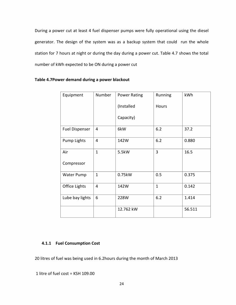
During a power cut at least 4 fuel dispenser pumps were fully operational using the diesel
generator. The design of the system was as a backup system that could run the whole
station for 7 hours at night or during the day during a power cut. Table 4.7 shows the total
number of kWh expected to be ON during a power cut
Table 4.7Power demand during a power blackout
Equipment Number Power Rating
(Installed
Capacity)
Running
Hours
kWh
Fuel Dispenser 4 6kW 6.2 37.2
Pump Lights 4 142W 6.2 0.880
Air
Compressor
1 5.5kW 3 16.5
Water Pump 1 0.75kW 0.5 0.375
Office Lights 4 142W 1 0.142
Lube bay lights 6 228W 6.2 1.414
12.762 kW 56.511
4.1.1 Fuel Consumption Cost
20 litres of fuel was being used in 6.2hours during the month of March 2013
1 litre of fuel cost = KSH 109.00
25
Hence total cost of 20 litres of fuel= KSH 2,180.00
For the Month of March 2013 the generator was filled with 80litres of fuel ,
Cost of fuel in March 2013= KSH 109.00x 80 = KSH 8,720.00
Assuming on average that the generator is filled with 80litres of fuel in a month, then
projecting the cost of fuel in one year will be KSH 8,720.00 x 12 = KSH 104,640.00
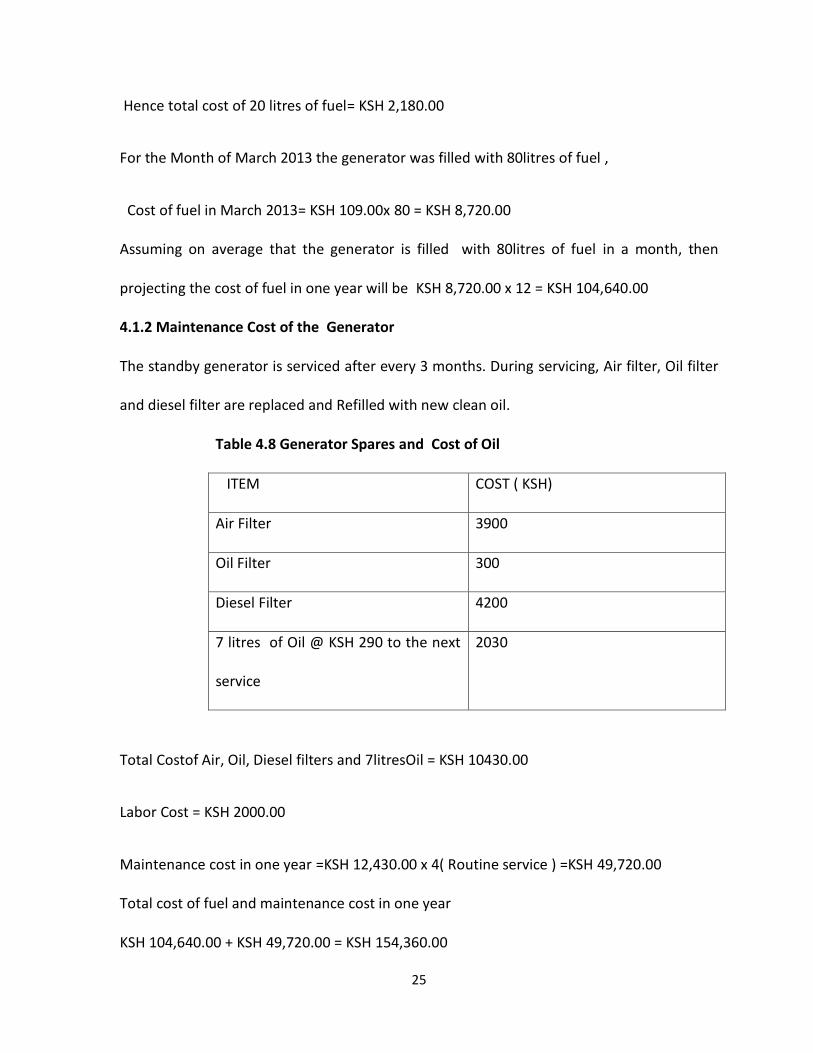
4.1.2 Maintenance Cost of the Generator
The standby generator is serviced after every 3 months. During servicing, Air filter, Oil filter
and diesel filter are replaced and Refilled with new clean oil.
Table 4.8 Generator Spares and Cost of Oil
ITEM COST ( KSH)
Air Filter 3900
Oil Filter 300
Diesel Filter 4200
7 litres of Oil @ KSH 290 to the next
service
2030
Total Costof Air, Oil, Diesel filters and 7litresOil = KSH 10430.00
Labor Cost = KSH 2000.00
Maintenance cost in one year =KSH 12,430.00 x 4( Routine service ) =KSH 49,720.00
Total cost of fuel and maintenance cost in one year
KSH 104,640.00 + KSH 49,720.00 = KSH 154,360.00

26
The initial purchasing and installation cost
Generator specifications
Rating 30KVA 41.7Amp 3phase
Initial Cost = KSH 800,000.00
Installation labor cost 15% of KSH 800,000.00 = KSH 120,000.00
Total Cost = KSH 920,000.00
4.2Photovoltaic system
The system will comprise of :- inverter, batteries , Solar Panels and Controller
Taking ascenario where all the equipments will be ON at the same time, we use a diversity
factor of 60% on installed capacity.
Generator maximum Current is 41.7 Amps
Hence 60% of 41.7 Amps = 25Amps
If the Generator is ON for 6.2hrs
Then 25Amps x 6.2hrs = 155Ah
The power consumed in 6.2hrs from table 4.7 = 56511.0Wh
Battery Design- Battery storage sizing depends on the duration of uninterrupted power
supply to the load when the photovoltaic system is in operation which occurs at night time
or during cloudy days . The battery backup systems are used to store electric energy
harvested from solar photovoltaic system for use during the absence of sunlight but for the
study it will be used in the absence of commercial power and at night.
The system design voltage is 12 Volts

27
A 12Volts battery ratedin the battery bank is to be used. The batteries have depth of 80%
discharge ,such that one cannot fully discharge the batteries .
56511.0Wh /12V= 4709.256
4709.25/0.8 discharge depth =5886.56AH
From the market a Battery which can discharge for between 6hrs to 10 hrs is of the model
of 12V 200AH.
Number of batteries required for the system
5886.56AH/200AH =29.43batteries= 30 batteries of 12Volts
Then 30batteries of12Volts are to be wired in parallel for the battery bank;-
The Solar battery type which are maintenance free are of the model 200AH which cost KSH
38,000.00 (Davis &Shirtliff Group, 2013)
Total cost of batteries 30 x 38,000 = KSH 1,140,000.00
4.2.1 Sizing of Photovoltaic Array
The solar panels willbe installed on top of the existing canopy. Hence given that there is no
vegetations creating shade around the canopy, we assume that the panels will receive
sunshine for at least 6hrs in a day
The power of the solar panels becomes;- The Panels are to charge at 12Volts
Power of equipment x Running Hrs / (0.85 ( Loss factor )x 6 hrs of sunshine)
Energy Required Wh/(0.85 ( Loss factor )x 6 hrs of sunshine)
Loss factor or system inefficiency include the humidity and high temperature in the equator
zone, battery charging and discharging loss and inverter conversion loss
28
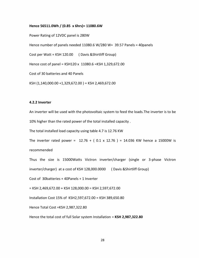
Hence 56511.0Wh / (0.85 x 6hrs)= 11080.6W
Power Rating of 12VDC panel is 280W
Hence number of panels needed 11080.6 W/280 W= 39.57 Panels = 40panels
Cost per Watt = KSH 120.00 ( Davis &Shirtliff Group)
Hence cost of panel = KSH120 x 11080.6 =KSH 1,329,672.00
Cost of 30 batteries and 40 Panels
KSH (1,140,000.00 +1,329,672.00 ) = KSH 2,469,672.00
4.2.2 Inverter
An inverter will be used with the photovoltaic system to feed the loads.The inverter is to be
10% higher than the rated power of the total installed capacity .
The total installed load capacity using table 4.7 is 12.76 KW
The inverter rated power = 12.76 + ( 0.1 x 12.76 ) = 14.036 KW hence a 15000W is
recommended
Thus the size is 15000Watts Victron inverter/charger (single or 3-phase Victron
inverter/charger) at a cost of KSH 128,000.0000 ( Davis &Shirtliff Group)
Cost of 30batteries + 40Panels + 1 Inverter
= KSH 2,469,672.00 + KSH 128,000.00 = KSH 2,597,672.00
Installation Cost 15% of KSH2,597,672.00 = KSH 389,650.80
Hence Total Cost =KSH 2,987,322.80
Hence the total cost of full Solar system Installation = KSH 2,987,322.80
29
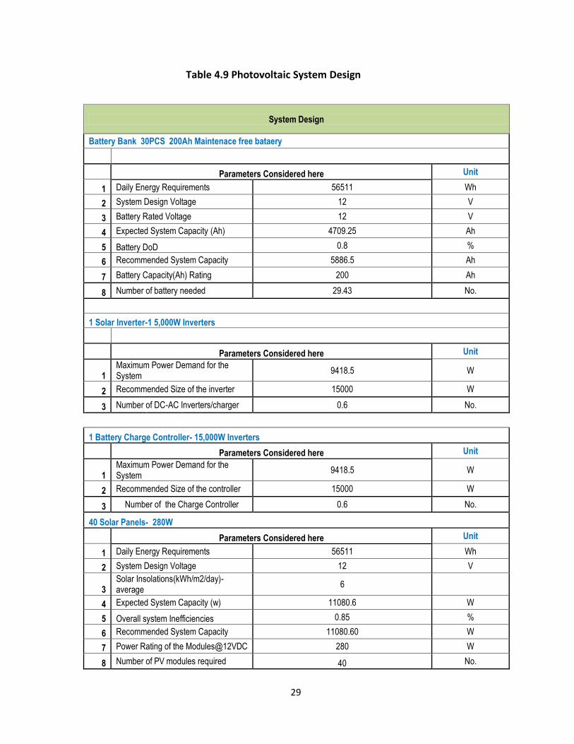
Table 4.9 Photovoltaic System Design
System Design
Battery Bank 30PCS 200Ah Maintenace free bataery
Parameters Considered here Unit
1 Daily Energy Requirements 56511 Wh
2 System Design Voltage 12 V
3 Battery Rated Voltage 12 V
4 Expected System Capacity (Ah) 4709.25 Ah
5 Battery DoD 0.8 %
6 Recommended System Capacity 5886.5 Ah
7 Battery Capacity(Ah) Rating 200 Ah
8 Number of battery needed 29.43 No.
1 Solar Inverter-1 5,000W Inverters
Parameters Considered here Unit
1 Maximum Power Demand for the System
9418.5 W
2 Recommended Size of the inverter 15000 W
3 Number of DC-AC Inverters/charger 0.6 No.
1 Battery Charge Controller- 15,000W Inverters
Parameters Considered here Unit
1 Maximum Power Demand for the System
9418.5 W
2 Recommended Size of the controller 15000 W
3 Number of the Charge Controller 0.6 No.
40 Solar Panels- 280W
Parameters Considered here Unit
1 Daily Energy Requirements 56511 Wh
2 System Design Voltage 12 V
3 Solar Insolations(kWh/m2/day)-average
6
4 Expected System Capacity (w) 11080.6 W
5 Overall system Inefficiencies 0.85 %
6 Recommended System Capacity 11080.60 W
7 Power Rating of the Modules@12VDC 280 W
8 Number of PV modules required 40 No.

30
CHAPTER FIVE
5.1 Solar Energy as an alternative Source of power for the Petrol Station
This research was to design a solar system to be used as a backup source of power for
6.2hrs; however the station can use the solar system fully to run all the operation because
the design of the battery is that they can store the charge between 6 to 10hrs when fully
charged. The manufacturer gives a span of five years when one can start doing maintenance
on the batteries. If the station is to use the solar fully then the payback period would be
shorter.Kenya is in the tropics and being a stride the equator and extending four degrees on
either side receives a considerable amount of solar radiation. This means that petrol station
can still be in full operation using solar power when the solar insolation is low especially
during a cold month like July or a cloudy day.
In any system there must be an alternative source or a backup system to come in during a
worst case scenario. If by any case the charge on the batteries will not be enough to run the
operations and the utility power is off then a stand by diesel generator is to be used as a
backup system to provide auxiliary power. The output of the diesel generator is to be
connected to the auxiliary input of the inverter to charge the solar batteries.
5.2 Conclusions
From the study photovoltaic system back up was designed to maintain the petrol station in
full operation for a maximum of 6.2 hours during a power blackout . The system
components includes:
1. PV Modules = 40PCS of 12VDC( 280W)
31
2. Inverter = 1 PCS of 15000W
3. Charge Controller=1 PCS of 15000W
4. Batteries = 30 PCS of 200AH Maintenance free
The initial cost of Solar power installation is KSH 2,987,322.80
from the analysis and the cost of installation and that of operating the diesel
enginegenerator in one year is KSH 920,000.00 . A sum of KSH2,067,322.80 ( operational
and maintenance cost of the generator) will be saved yearly when the solar system will be
installed since the solar system is maintenance free .
In spite of the low initial cost of diesel the generatorin operating the station has some
drawbacks . The generator need continuous maintenance and have a reduced life time and
has to be constantly fueled . Itproduces a lot of noise to the surrounding business premises
and pollutes the environment with smoke from the exhaust and if replaced by Solar to
power the station there will be no noise and there will be no greenhouse gas emissions
being released to the atmosphere
32
5.3 Recommendations
1. From the study a photovoltaic stand alone systems can be used in applications for petrol
stations in remote areas and especially in areas not covered by the grid utility. In areas
covered by the grid utility, the use of photovoltaic system as a standby system in a petrol
station is a better option than using diesel engine generators.
2.Research on the intelligent inverters which can be switched ON from Battery bank when
discharged capacity is reached and the mains electrical power can be carried out to fully
automate the petrol station.
33
REFERENCES
Davis &Shirtliff Group,” Solar Equipments “, www.dayliff.com, Accessed on 7th February
2013.
Eastop T D, Mcconkey A ,” Applied Thermodynamics for Engineering Technologists “, Fifth
edition, Longman group, UK 1993.
Kenya Energy Situation-energypedia.info
(http://energypedia.info/wiki/kenya_Energy.Situation 20june 2013)
Kenya(2012)- Policy and Regulatory overviews-Clean Energy (http://www.reegle.info/policy-
and-regulatory-overviews/KE)
National Oil of Kenya(http://en.wikipedia.org/wiki/National_oil_of_kenya accessed
24/2/13).
Turner W C, Doty S , “Energy Management Handbook “, Sixth edition, Fairmont Press, USA
2009.
Ubbink East Africa Ltd, “Solar Energy “, www.ubbink.co.ke, Accesed on 17th April 2013.