Embed Size (px)
Citation preview

'
&
$
%
Research
Operation of a Photovoltaic Microinverter as Active PowerFilter using the single phase P-Q Theory and Sliding ModeControlOperacion de un Microinversor Fotovoltaico como Filtro Activo de PotenciaUsando la Teorıa P-Q Monofasica y Control en Modo DeslizanteOswaldo Lopez-Santos1 , Sebastian Tilaguy-Lezama1 , Sandra P.Rico-Ramırez1 , Luis Cortes-Torres1
1Universidad de Ibague. Tolima - ColombiaCorrespondence: [email protected].
Received: 22/12/2016. Modified: 15/02/2017. Accepted: 28/03/2017.
'
&
$
%
AbstractContext: Microinverters are widely used in modular photovoltaic installations but its operation withreduced power is limited to inject real power into the grid. One way to optimize the use of microinver-ters consist of providing them the Active Power Filtering (APF) capability, which allows its use as bothdistributed generation and compensation unit even under unfavorable conditions of insolation. With thisapproach, the output stage of the microinverter can provide reactive and distortive components of powerin order to compensate power quality defects of a localized load.Method: This paper proposes a non-linear control strategy to integrate the APF function in a single-phase two-stage photovoltaic microinverter. The proposal involves the use of the single-phase P-Q theoryto generate the current reference, sliding mode control to achieve a robust tracking of that reference andlinear robust control to maintain the power balance regulating the DC-link voltage of the microinverter.The proposed control does not require the use of low-pass filters and in turn uses a recursive averagecomputation improving the general performance of the system.Results: The theoretical approach is validated by means of simulation results in which appropriate levelsof harmonic distortion are obtained in the grid-side current for different load types and power levels. Therobustness of the control system is tested by applying disturbances in the harmonic content of the loadcurrent and its power level obtaining an appropriate dynamic performance adapted to the demands of theapplication.Conclusions: The main advantage of this proposal is the possibility to add the active filter function to co-ventional microinverters extending its capability to power conditioning only integrating some algorithms.A simple design method to ensure reliability, robustness and high power quality is detailed.Keywords: Microinverter, Active power filter, Single-phase PQ theory, Sliding-mode control, Non-Linear controlLanguage: EnglishAcknowledgements: This research is being developed with the partial support of the Gobernacion delTolima - Convenio de cooperacion 1026- 2013 - Research Culture and the Universidad de Ibague underproject 16-406-SEM with the assistance of students from the Research Hotbed on Control and PowerElectronics (SICEP), Research Group D+TEC.
Citation: O. Lopez, S. Tilaguy, S. P. Rico, L. Cortes, “Operation of a Photovoltaic Microinverter as Active Power Filter usingthe single phase P-Q Theory and Sliding Mode Control” INGENIERIA, vol. 22, no. 2, pp. 254-268, 2017.c©Los autores; titular de derechos de reproduccion Universidad Distrital Francisco Jose de Caldas. En lınea DOI:
http://dx.doi.org/10.14483/udistrital.jour.reving.2017.2.a06
254 INGENIERIA • VOL. 22 • NO. 2 • ISSN 0121-750X • E-ISSN 2344-8393 • UNIVERSIDAD DISTRITAL FRANCISCO JOSE DE CALDAS

O. Lopez • S. Tilaguy • S. P. Rico • L. Cortes
'
&
$
%
Resumen
Contexto: Los microinversores son ampliamente utilizados en instalaciones fotovoltaicas modulares perosu operacion con potencia reducida es limitada a inyectar potencia real en la red. Una forma de optimizarel uso de los microinversores consiste en proveerles la capacidad para realizar Filtrado Activo de Potencia(FAP), lo que permite su uso como una unidad tanto de generacion como de compensacion distribuida,incluso en condiciones desfavorables de irradiacion solar. Con esta propuesta, la etapa de salida del mi-croinversor puede suministrar componentes de potencia reactiva y de distorsion para compensar defectosen la calidad de energıa de una carga localizada.Metodo: Se propone una estrategia de control no lineal para integrar la funcion FAP en un microinversorfotovoltaico monofasico de dos etapas. La propuesta involucra el uso de la teorıa P-Q monofasica paragenerar la referencia de corriente, control en modo deslizante para conseguir un seguimiento robusto dedicha referencia y control lineal robusto para mantener el balance de potencia regulando el voltaje delbus DC intermedio del microinversor. El control propuesto no requiere del uso de filtros pasa-bajos y encambio usa un computo recursivo de valor promedio, mejorando el desempeno general del sistema.Resultados: La propuesta teorica es validada usando resultados de simulacion en los que se evidencianniveles apropiados de distorsion armonica en la corriente de la red, los cuales se obtienen para diferentestipos de carga y niveles de potencia. La robustez del sistema de control es puesta a prueba aplicandoperturbaciones en el contenido armonico de la corriente de la carga y su nivel de potencia obteniendo undesempeno dinamico adecuado para las exigencias de la aplicacion.Conclusiones: La principal ventaja obtenida con el sistema de control propuesto es la posibilidad deadicionar la funcion de filtrado activo a los microinversores convencionales para extender su contribucionhacia el acondicionamiento electrico con la integraccion de algunos algoritmos. Se detalla un disenosimple para asegurar confiabilidad, robustez y altos niveles de calidad de potencia.Palabras clave: Microinversor, Filtro activo de potencia, Teorıa P-Q monofasica, Control en modo des-lizante, Control no lineal.Idioma: InglesAgradecimientos: Esta investigacion ha sido financiada parcialmente por la Gobernacion del Tolimasegun el Convenio de cooperacion 1026- 2013 – Cultura cientıfica y la Universidad de Ibague a travesdel proyecto 16-406-SEM con la asistencia de estudiantes del Semillero de Investigacion en Control yElectronica de Potencia (SICEP) del Grupo de investigacion D+TEC.
1. Introduction
The photovoltaic microinverter technology is a recent development in the field of power elec-tronics which has allowed the modularization of the photovoltaic installations and in consequen-ce has disseminated the proliferation of the distributed generation around the world [1]–[3]. Thistechnology allows overlooking, at least to a large extent, the problems related with the use of pho-tovoltaic arrays such as mismatching and partial shading [4]. Nevertheless, the functionality of themicroinverters remains limited to inject into the grid the real power obtained from solar moduleswhat is insufficient when there are no other representative power sources supporting the furtherpower components. This aspect motivates the research dedicated to expand the capabilities of themicroinverters including the generation of reactive and harmonic power with the aim to cover therequirements of reactive and nonlinear loads [5], [6].
INGENIERIA • VOL. 22 • NO. 2 • ISSN 0121-750X • E-ISSN 2344-8393 • UNIVERSIDAD DISTRITAL FRANCISCO JOSE DE CALDAS 255
Operation of a Photovoltaic Microinverter as Active Power Filter using the single phase P-Q Theory and Sliding Mode C.
The current motivation is to achieve that the microinverter technology play a new role in ACdistribution systems complementing their main objective of real power injection with capabilitiesof power conditioning [7]–[9]. This new approach introduces the distributed generation- condi-tioning concept, taking full advantage of the converters on the microinverter devices [10]. Thus,microinverters will be capable to generate a programmed amount of reactive power, a programmedharmonic content, or as it is presented in this paper, they can compensate the reactive and distor-tive power of localized loads. As a drawback, it is worth mentioning that the measurement of anadditional current increases the cost of the system.
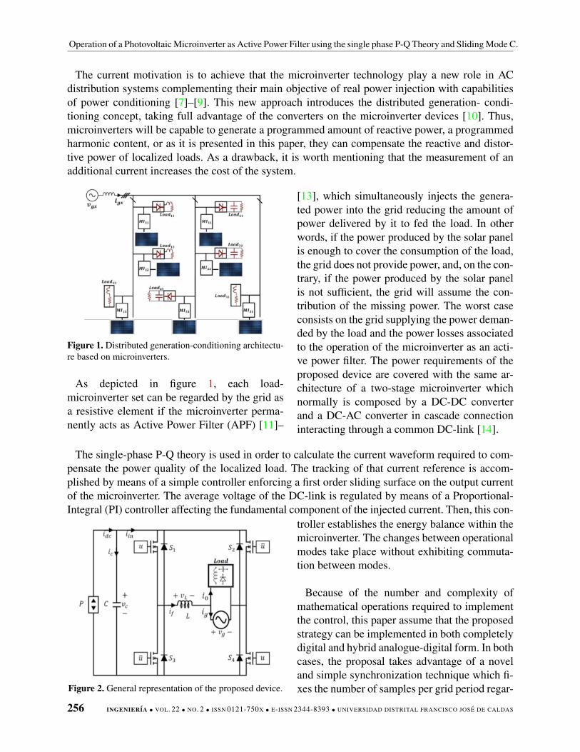
Figure 1. Distributed generation-conditioning architectu-re based on microinverters.
As depicted in figure 1, each load-microinverter set can be regarded by the grid asa resistive element if the microinverter perma-nently acts as Active Power Filter (APF) [11]–
[13], which simultaneously injects the genera-ted power into the grid reducing the amount ofpower delivered by it to fed the load. In otherwords, if the power produced by the solar panelis enough to cover the consumption of the load,the grid does not provide power, and, on the con-trary, if the power produced by the solar panelis not sufficient, the grid will assume the con-tribution of the missing power. The worst caseconsists on the grid supplying the power deman-ded by the load and the power losses associatedto the operation of the microinverter as an acti-ve power filter. The power requirements of theproposed device are covered with the same ar-chitecture of a two-stage microinverter whichnormally is composed by a DC-DC converterand a DC-AC converter in cascade connectioninteracting through a common DC-link [14].
The single-phase P-Q theory is used in order to calculate the current waveform required to com-pensate the power quality of the localized load. The tracking of that current reference is accom-plished by means of a simple controller enforcing a first order sliding surface on the output currentof the microinverter. The average voltage of the DC-link is regulated by means of a Proportional-Integral (PI) controller affecting the fundamental component of the injected current. Then, this con-
Figure 2. General representation of the proposed device.
troller establishes the energy balance within themicroinverter. The changes between operationalmodes take place without exhibiting commuta-tion between modes.
Because of the number and complexity ofmathematical operations required to implementthe control, this paper assume that the proposedstrategy can be implemented in both completelydigital and hybrid analogue-digital form. In bothcases, the proposal takes advantage of a noveland simple synchronization technique which fi-xes the number of samples per grid period regar-
256 INGENIERIA • VOL. 22 • NO. 2 • ISSN 0121-750X • E-ISSN 2344-8393 • UNIVERSIDAD DISTRITAL FRANCISCO JOSE DE CALDAS

O. Lopez • S. Tilaguy • S. P. Rico • L. Cortes
dless the current value of the grid frequency [15]. Advantages and particularities of the proposedimplementation are detailed and validated later.
The rest of the paper is organized as follows. Section 2 gives a general description of the systemand its main characteristics whereas section 3 details the components of the proposed control. Afterthat, several simulation results validating theoretical analysis are presented in section 4. Finally,conclusions are presented in section 5.
2. General DescriptionThe output stage of a two-stage microinverter is a conventional full-bridge grid-connected DC-
AC converter. To separate the analysis of both stages of the microinverter, the set consisting of thesolar panel and the DC-DC stage can be considered as a power source as was introduced in [16],[17]. The circuit configuration takes the form represented in figure 2. The power source P representsthe power available at the DC-link which is sourced by the solar panel through the DC-DC conver-ter. The capacitor C serves as coupling element between DC-DC and DC-AC converters while theinductor L serves as coupling element between the DC-AC converter and the grid. The voltage vgis the grid voltage which is the same output voltage of the microinverter and input voltage of thecompensated load. The output current of the microinverter, the current of the load and the resultingcurrent of the grid were named as if , io and ig respectively. The bridge is controlled by means ofthe signal u applied directly to the interrupters S1 and S4 , and the complementary signal u = 1−uapplied to the interrupters S2 and S3, this control inducing bipolar commutation. The current idcrepresents the current given by the power source P while the current iin represents the input currentof the full bridge.
Taking as starting point strategy proposed in [18] to control the output stage of a solar microin-verter, the functions related with the active power filter capability were integrated, obtaining theblock diagram depicted in figure 3. The blocks of single-phase P-Q theory, synchronization andsine-wave reference generation, ripple estimation, amplitude estimation and DC-link control areexplained in detail in the following section.
Figure 3. Block diagram representing the control requirements of the proposed power converter application.
INGENIERIA • VOL. 22 • NO. 2 • ISSN 0121-750X • E-ISSN 2344-8393 • UNIVERSIDAD DISTRITAL FRANCISCO JOSE DE CALDAS 257
Operation of a Photovoltaic Microinverter as Active Power Filter using the single phase P-Q Theory and Sliding Mode C.
3. Calculations, modeling and control
3.1. Modified single phase PQ theory
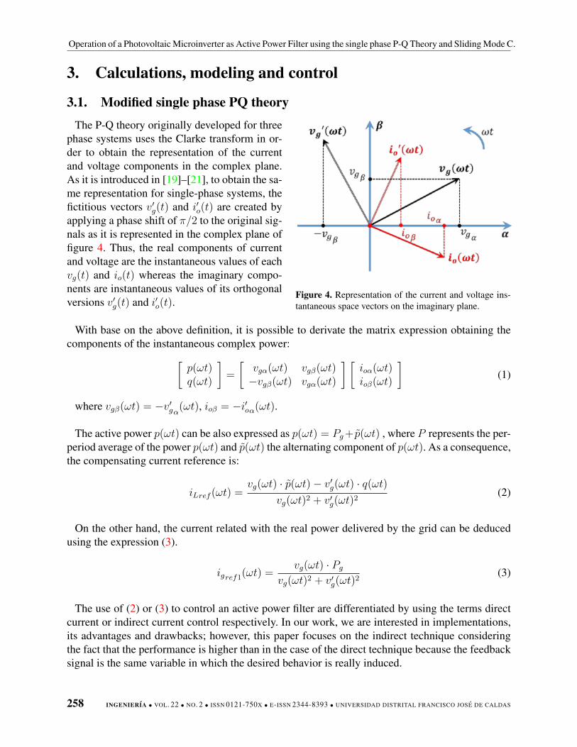
The P-Q theory originally developed for threephase systems uses the Clarke transform in or-der to obtain the representation of the currentand voltage components in the complex plane.As it is introduced in [19]–[21], to obtain the sa-me representation for single-phase systems, thefictitious vectors v′g(t) and i′o(t) are created byapplying a phase shift of π/2 to the original sig-nals as it is represented in the complex plane offigure 4. Thus, the real components of currentand voltage are the instantaneous values of eachvg(t) and io(t) whereas the imaginary compo-nents are instantaneous values of its orthogonalversions v′g(t) and i′o(t).
Figure 4. Representation of the current and voltage ins-tantaneous space vectors on the imaginary plane.
With base on the above definition, it is possible to derivate the matrix expression obtaining thecomponents of the instantaneous complex power:[
p(ωt)q(ωt)
]=
[vgα(ωt) vgβ(ωt)−vgβ(ωt) vgα(ωt)
] [ioα(ωt)ioβ(ωt)
](1)
where vgβ(ωt) = −v′gα(ωt), ioβ = −i′oα(ωt).
The active power p(ωt) can be also expressed as p(ωt) = Pg+ p(ωt) , where P represents the per-period average of the power p(ωt) and p(ωt) the alternating component of p(ωt). As a consequence,the compensating current reference is:
iLref (ωt) =vg(ωt) · p(ωt)− v′g(ωt) · q(ωt)
vg(ωt)2 + v′g(ωt)2
(2)
On the other hand, the current related with the real power delivered by the grid can be deducedusing the expression (3).
igref1(ωt) =vg(ωt) · Pg
vg(ωt)2 + v′g(ωt)2
(3)
The use of (2) or (3) to control an active power filter are differentiated by using the terms directcurrent or indirect current control respectively. In our work, we are interested in implementations,its advantages and drawbacks; however, this paper focuses on the indirect technique consideringthe fact that the performance is higher than in the case of the direct technique because the feedbacksignal is the same variable in which the desired behavior is really induced.
258 INGENIERIA • VOL. 22 • NO. 2 • ISSN 0121-750X • E-ISSN 2344-8393 • UNIVERSIDAD DISTRITAL FRANCISCO JOSE DE CALDAS

O. Lopez • S. Tilaguy • S. P. Rico • L. Cortes
The fundamental difference between the ori-ginal P-Q theory and the modified P-Q theoryis the use of a phase looked loop (PLL) to ob-tain the measured voltage vg1(ωt) which allowsovercomes the negative effects of distortions inthe estimation of the compensation current [22].As it is detailed below, the use of a specific kindof PLL brings some relevant advantages to thesystem. The block diagram representing the ap-plied P-Q theory is shown in figure 5. It is worthto highlight that the term vg1(ωt)
2+v′g1(ωt)2 be-
comes V 2gmax because both vg1(ωt) and v′g1(ωt)
are pure sine waveforms generated by the PLL. Figure 5. Block diagram of the single-phase P-Q theoryimplementation.
3.2. Synchronization and sine-wave generation
The P-Q theory was implemented with base on the grid synchronization system proposed in [15].In this system, it is generated a sine waveform synchronized in frequency and phase with the gridusing N = 1024 samples per period and consequently a high frequency N times higher than thegrid frequency. That frequency is used to synchronize the execution of the control algorithms intothe digital device with the following advantages:
• The commonly used low-pass filter required extracting the average power component andits delay effect are replaced by a recursive moving average filter (RMAF) improving noiseand harmonic rejection, and reducing computational cost [23], [24]. The number of samplesin the average is equal to N (1024) which is the same number of samples for a grid period;therefore, it is ensuring a high accuracy of the average computation and in consequence ahigh quality in the reference generation.
• The phase displacements required to generate the fictitious vector of the P-Q theory are highlyaccurate and no dependent of the grid frequency. A phase shift of 90 simply corresponds toa delay of 256 samples in the waveforms.
• Computations based on integrals averaged for a period of the grid frequency (average, RMSor FFT calculations) has a lower computational cost facilitating the optimization of executiontime of per sample algorithm.
The same synchronization system provides the fundamental component required to inject thegenerated real power into the grid or in other case to extract the power to cover the power lossesof the inverter. Complementarily, the PLL generates a double frequency component in order toestimate and cancel the effect of the voltage ripple of the DC-link in the control loops [25]. It isworth to mention that, the loop controller of the PLL also uses the RMAF instead of conventionallow-pass filters.
INGENIERIA • VOL. 22 • NO. 2 • ISSN 0121-750X • E-ISSN 2344-8393 • UNIVERSIDAD DISTRITAL FRANCISCO JOSE DE CALDAS 259

Operation of a Photovoltaic Microinverter as Active Power Filter using the single phase P-Q Theory and Sliding Mode C.
3.3. Tracking of the current referenceThe model of the grid-connected power converter can be expressed with the bilinear equation
system:
LdiLdt
= −vg + vcu (4)
Cdvcdt
=P
vc− iLu
ig = iL − io
The tracking of the current reference is accomplished by means of a sliding-mode controller. Thiskind of control has been used with the same purpose by other authors [26]–[28] and it is selectedconsidering its advantages such as rapid response, robustness against external disturbances andparameter uncertainty, despite of the well know disadvantage of variable frequency commutationwhen it is implemented using a hysteresis comparator with constant band.
The following first order sliding surface is defined:
S(x) = igref − ig = Igmax sinωt− ig (5)
where igref is the reference current given by the P-Q theory computation. Analyzing the stabilityof sliding mode control the design requires fulfilling the transversality and reachability conditions.The transversality condition guarantees that the control variable u is present in the switching fun-ction derivate, or in other words to satisfy that dS(x)
du6= 0. To analyze this condition, time derivative
of the sliding surface is obtained from (7) and (4) and after that the derivative of this result withrespect to the control signal is obtained as follows:
d
du(S(x)) = −vC
L(6)
Then, it was established that the transversality condition is fulfilled while the voltage of the DClink is different to zero which is true for every operational condition. In the worst case, the absen-ce of control signals enforces the converter to operate as a diode bridge rectifier with an outputcapacitance ensuring a minimum voltage near to the peak value of vg. The sign of transversalityis negative and then, the sliding motion around the current reference is obtained by applying thefollowing control law:
u =
−1 when S(x) > 01 when S(x) < 0
(7)
Because of the limitations of the electronic po-wer devices to obtain infinite frequency commu-tation as suggest the application of sliding modecontrol, the control law (7) cannot be implemen-ted directly and the switching frequency must belimited below admissible values. Then, the con-troller is implemented using a hysteresis com-parator with a band of ±∆ as it is depicted infigure 6.
Figure 6. Circuit implementation of the sliding mode ba-sed current controller.
260 INGENIERIA • VOL. 22 • NO. 2 • ISSN 0121-750X • E-ISSN 2344-8393 • UNIVERSIDAD DISTRITAL FRANCISCO JOSE DE CALDAS

O. Lopez • S. Tilaguy • S. P. Rico • L. Cortes
The reachability condition is used to determinate the capacity of system to reach the slidingsurface from whatever arbitrary point. The reachability depends of the sign of transversality [30],and therefore its definition is:
lımS(x)→0−
S(x)|u=−1 > 0 (8)
lımS(x)→0+
S(x)|u=1 < 0 (9)
By applying the above definition in the system equations, the following condition is obtained:∣∣∣∣ωLIgmax cosωt+ Ldiodt
+ Vmax sinωt
∣∣∣∣ < Vc (10)
In general terms, expression (10) shows that the value of Vref must be selected is such a way thata considerable difference exist between the minimum value of vc including its ripple componentand the maximum value of vg. Beyond to satisfy (10), the possible deviation of vc during transitorydisturbance events must be even considered.
Finally, applying the invariance conditions defined as S(X) = 0 and S(x) = 0|u=ueq and theequivalent control method [29], the resulting dynamics is:
ig = igref∼= Igmax sinωt (11)
CVCdVcdt
= P − iL[L
(digrefdt
+diodt
)+ Vg
](12)
By averaging expressions for a half grid period, linearizing and applying the Laplace transform,it is obtained that:
Vc(s) =2LIos− Vmax
2VrefCsIgmax(s) +
1
CVrefsP (s) +
LIoCVref
Io(s) (13)
From (13), the transfer function of the DC link voltage to the output corrent amplitude can beused to synthesize a voltage regulator considering both the load current and the input power asdisturbances.
3.4. DC-link voltage regulationAs it is explained in [31], a PI controller with a low-pass filter term can be applied in order to
obtain zero error regulation of the DC-link voltage. This simple linear controller can reduce theeffect of the double grid frequency component in the measurement of the DC link voltage andreject the possible power disturbances of power and load current. The controller has the form:
C(s) =Kps+Ki
s(Tfs+ 1)(14)
The value of Tf is selected in order to considerable decrease the ripple component of 120 Hz inthe DC link voltage. The Kp and Ki parameters are selected in order to ensure robustness against
INGENIERIA • VOL. 22 • NO. 2 • ISSN 0121-750X • E-ISSN 2344-8393 • UNIVERSIDAD DISTRITAL FRANCISCO JOSE DE CALDAS 261

Operation of a Photovoltaic Microinverter as Active Power Filter using the single phase P-Q Theory and Sliding Mode C.
Figure 7. Robust loop shaping optimization in the Kp-Ki
plane.Figure 8. Nyquist curves and robustness region.
disturbances and parameter uncertainties. This objective can be accomplished by using the loopshaping method introduced in [32]. A value of 2 is selected for the combined sensitivity M follo-wing criteria presented in [33].
Figure 7 shows the two envelopes resulting after generate the whole space of solutions in theKp - Ki plane ensuring robustness for input power values of 10 W (red color) and 100 W (bluecolor). The best solution is that which maximizes Ki outside of the shaded areas which results inKp = 0,0562 and Ki = 2,08 for the set of converter parameters in table I. With these parameters,the Nyquist curves of the loop transfer function L(s) = Igmax(s)
−1Vc(s)C(s) for the two limitvalues of power are depicted in figure 8. As it can be noted the robustness constrain was fulfilledwith the selected controller parameters.
4. Simulation resultsIn order to validate the entire proposal and the applied concepts, several simulations have been
implemented. Two type of load with two different power levels for each one have been used, aninductive-resistive load and a nonlinear load composed by a diode bridge rectifier with an inductive-resistive load at the DC side. The parameters used are listed in table I.
Table I. Converter and control parameters.Parameter Symbol Value Units Parameter Symbol Value Units
Converter parameters Control parametersNominal grid voltage Vg 120 V Proportional gain Kp 0.18 Ω−1
Nominal grid frequency fg 60 Hz Integral gain Ki 0.1 Ω−1
DC-link capacitor C 100 µF Filtering time constant Tf 0.005 Ω−1/sCoupling Inductor L 10 mH Hysteresis band ±∆ ± 0.07 ADC-link voltage Vref 240 V
4.1. Steady-state performance (PF and THD)Figure 9 shows simulated results evaluating the steady-state performance of the control system for
two of the selected loads defined in Table II (Load 1 and Load 3) when the microinverter operates
262 INGENIERIA • VOL. 22 • NO. 2 • ISSN 0121-750X • E-ISSN 2344-8393 • UNIVERSIDAD DISTRITAL FRANCISCO JOSE DE CALDAS

O. Lopez • S. Tilaguy • S. P. Rico • L. Cortes
as an active filter because of the absence of input power. The THD of the waveforms is given inorder to show the effect of the compensation algorithm. In the first case, the RL load is demandingreactive power which is entirely delivered by the microinverter obtaining unitary DPF and PF.
Table II. Load ParametersParameter Symbol Value Units Parameter Symbol Value Units
Load 1 parameters (RL) Load 2 parameters (RL)Aparent power (60 Hz) So 370 VA Aparent power (120 V/60 Hz) So 46 VA
Power factor PF 0.26 - Power factor PF 0.26 -Resistance Ro 10 Ω Resistance Ro 80 ΩInductance Lo 0.1 H Inductance Lo 0.8 H
Load 3 parameters (DRL) Load 4 parameters (DRL)Aparent power (120 V/60 Hz) So 162 VA Aparent power (120 V/60 Hz) So 16 VA
Power factor PF 0.9 - Power factor PF 0.9 -Total Harmonic Distortion THD 47 % Total Harmonic Distortion THD 47 %
Resistance Ro 80 Ω Resistance Ro 800 ΩInductance Lo 0.8 H Inductance Lo 8 H
The figure 9a show the way in that the grid delivers a sinusoidal current without any phase shiftrespect to the voltage. The THD only increases a 0.30 % because of the high frequency componentintroduced by the microinverter. In the second case which is shown in figure 9b, the nonlinear loadhas not phase displacement but has a high harmonic content (47.3 %). The microinverter compen-sates the load allowing to obtain unitary PF. The THD of the grid current is reduced below 4 %. Inboth cases the THD of the current is below of 5 % which corresponds to a permissive value accor-ding to the actual normativity [34], [35]. Also in both cases, the power factor is compensated.
Figure 10 shows a complete analysis of the THD and PF obtained with the active filtering fun-ction of the microinverter for the overall operational range of load power and AC input voltage.Information was organized in 3D surfaces showing the simultaneous relation of each power qualityindicator as function of both selected parameters. The first case corresponds to a RL load and thesecond case corresponds to a nonlinear load obtained with a diode bridge feeding a RL load. Pointsin surfaces were obtained using input voltage values between 110 and 130 V with steps of 5 V, and
Figure 9. Simulated steady-state voltage and current waveforms for Load 1 and Load 3: a) Load 1 [100V/div, 2A/div,0.5A/div, 2A/div]; b) Load 3 [100V/div, 0.5A/div, 1A/div, 0.5A/div].
INGENIERIA • VOL. 22 • NO. 2 • ISSN 0121-750X • E-ISSN 2344-8393 • UNIVERSIDAD DISTRITAL FRANCISCO JOSE DE CALDAS 263

Operation of a Photovoltaic Microinverter as Active Power Filter using the single phase P-Q Theory and Sliding Mode C.
Figure 10. Total Harmonic Distortion (THD) vs. input voltage and load impedance: a) RL load, b) Nonlinear load.Power Factor (PF) vs. input voltage and load impedance: c) RL load; d) Nonlinear load.
load impedances between 5 and 55 Ω for the first case and between 60 and 110 Ω for the secondcase, considering steps of 5 Ω in both cases.
4.2. Transient response to input power and load disturbancesFigure 11 shows simulated results evaluating the transient response of the system when input po-
wer disturbances are applied. In subfigures 10a and 10b an input power change is applied at 0.4 schanging its value from 20 to 100 W. After that at 0.6 s, input power suddenly reduces to zero. Thevoltage of the DC-link absorbs the power disturbance returning to the desired value in less than 75ms in both cases with voltage deviations lower than 10 %. This results show the robust response ofthe system rejecting power disturbances.
Figure 12 shows simulated results evaluating the transient response of the system when loadchanges are applied. The system operates with the load 1 0.4 s when the load 3 is added. After that,at 0.8 s, the load 1 is disconnected and the load 3 keeps connected. As it is can be noted, the systemhas the ability to cope with load changes without problem.
264 INGENIERIA • VOL. 22 • NO. 2 • ISSN 0121-750X • E-ISSN 2344-8393 • UNIVERSIDAD DISTRITAL FRANCISCO JOSE DE CALDAS

O. Lopez • S. Tilaguy • S. P. Rico • L. Cortes
Figure 11. Transient response of the system coping with input power disturbances. a) Load 1 is connected. Scales:[20W/div, 20V/div, 2A/div, 100V/div, 0.5A/div, 2A/div]; b) Load 2 is connected. Scales: [20W/div, 10V/div, 0.5A/div,100V/div, 0.5A/div, 1A/div].
Figure 12. Simulated waveforms of transient responses of the system coping with load disturbances: e) system feedingload 1, load 2 or both [100V/div, 2A/div, 5A/div, 5A/div].
5. Conclusions
A new distributed power generation-compensation architecture based on single-phase microin-verters has been presented. The main idea is to integrate the active power factor correction functionin these devices taking advantage of the output-stage even if there is no production of photovol-taic solar energy. The proposal was validated by means of several simulation results evaluating thesteady-state and dynamic performance of the converter working with different types of electricalloads and two different power levels for each of them. In the steady state, the obtained power factoris unitary and the THD in the grid current is reduced always below 5 % what is in good agreementwith the established standards. The performance of the microinverter coping with transient eventswas evaluated by applying disturbances in both input power and power load. The design of the
INGENIERIA • VOL. 22 • NO. 2 • ISSN 0121-750X • E-ISSN 2344-8393 • UNIVERSIDAD DISTRITAL FRANCISCO JOSE DE CALDAS 265

Operation of a Photovoltaic Microinverter as Active Power Filter using the single phase P-Q Theory and Sliding Mode C.
DC link voltage regulator using the robust loop shaping technique allowed to reduce the impactof disturbances obtaining voltage deviations below 10 % and reduced settling times below 75 ms.Compatibility of the P-Q theory in the reference generation, sliding mode control in the currentcontroller and robust PI compensation in the DC link voltage control was facilitated by the useof a recursive moving average filter in which the number of samples is constant in a grid perioddespite of changes in the grid frequency. The current and future efforts are concentrated obtainingan experimental validation of the overall approach in which all control function are embedded ina digital signal processing device looking for a really optimized utilization of the computation andmemory resources.
References[1] H. A. Sher, and K.E. Addoweesh, “Micro-inverters - Promising Solutions in Solar Photovoltaics,” Energy for
Sustainable Development, vol. 16, pp. 389-400, Dec. 2012. ↑255[2] F. Blaabjerg, Z. Chen, and S.B. Kjaer, “Power electronics as efficient interface in dispersed power generation
systems,” IEEE Trans. Power Electron., vol. 19, no. 5, pp. 1184-1194, Sep. 2004. ↑255[3] Y. Xue, L. Chang; S.B. Kjaer, J. Bordonau, and T. Shimizu, “Topologies of single-phase inverters for small dis-
tributed power generators: an overview,” IEEE Trans. Power Electron., vol. 19, no. 5, pp. 1305-1314, Sep. 2004. ↑255
[4] J.D. Bastidas, C.A. Ramos-Paja, and E. Franco, “Modeling and parameter calculation of photovoltaic fields inirregular weather conditions,” Revista INGENIERIA, vol. 17, no. 1, pp. 37-48, Jun. 2012. ↑255
[5] M. Molinas and J. Kondoh, “Power electronic loads as providers of reactive power ancillary service to the grid:Analytical and experimental study,” in Proc. 13th European Conference on Power Electronics and Applications(EPE), Barcelona, 2009, pp. 1-10. ↑255
[6] W. Abbas and M. A. Saqib, “Effect of Nonlinear Load Distributions on Total Harmonic Distortion in a PowerSystem,” in Proc. International Conference on Electrical Engineering (ICEE), Lahore, 2007, pp. 1-6. ↑255
[7] C. H. Chang, Y. H. Lin, Y. M. Chen and Y. R. Chang, “Simplified Reactive Power Control for Single-Phase Grid-Connected Photovoltaic Inverters,” IEEE Trans. Ind. Electron., vol. 61, no. 5, pp. 2286-2296, May 2014. ↑256
[8] M. Islam, N. Afrin and S. Mekhilef, “Efficient Single Phase Transformerless Inverter for Grid-Tied PVG SystemWith Reactive Power Control,” IEEE Trans. Sustainable Energy, vol. 7, no. 3, pp. 1205-1215, July 2016. ↑256
[9] I. Bouloumpasis, P. Vovos, K. Georgakas, and N.A. Vovos, “Current harmonics compensation in microgrids ex-ploiting the power electronics interfaces of renewable energy sources,” Energies, vol. 8, no. 4, pp. 2295-2311, Aug.2015. ↑256
[10] F.P. de Souza and I. Barbi, “Single-phase active power filters for distributed power factor correction,” in Proc.IEEE 31st Annual Power Electronics Specialists Conference (PESC), Galway, 2000, pp. 500-505. ↑256
[11] O. Lopez-Santos, “Filtro activo paralelo para compensacion de factor de potencia y distorsion armonica en apli-caciones industriales,” Master thesis, Universidad Nacional de Colombia, 2010. ↑256
[12] F.R. Jimenez, J.M. Salamanca, & P.F. Cardenas, “Modeling and circuital analysis of a Single Phase Shunt ActivePower Filter,” In 2014 IEEE 5th Colombian Workshop on Circuits and Systems (CWCAS), Barranquilla, 2014. ↑256
[13] Hua, C-C. Li, C-H. Lee, C-S. “Control Analysis of an active power filter using Lyapunov candidate,” IET PowerElectron., vol. 2. no. 4, April 2009. ↑256
[14] O. Lopez-Santos, L. Martinez-Salamero, G. Garcia, & H. Valderrama-Blavi, “Sliding-mode control of a transfor-merless dual-stage grid-connected photovoltaic micro-inverter,” In Proc. 10th IEEE International Multi-Conferenceon Systems, Signals & Devices (SSD), pp. 1-6, 2013. ↑256
[15] O. Lopez-Santos, G. Garcia, J.C. Avila-Martinez, D.F. Gonzalez-Morales, & C. Toro-Zuluaga. “A simple digitalsinusoidal reference generator for grid-synchronized power electronics applications,” In Proc. IEEE Workshop onPower Electronics and Power Quality Applications (PEPQA), pp. 1-6, 2015. ↑257, 259
[16] O. Lopez-Santos, “Contribution to the DC-AC conversion in photovoltaic systems: Module oriented converters,”Doctoral dissertation, INSA de Toulouse, pp. 1-248, 2015. ↑257
266 INGENIERIA • VOL. 22 • NO. 2 • ISSN 0121-750X • E-ISSN 2344-8393 • UNIVERSIDAD DISTRITAL FRANCISCO JOSE DE CALDAS

O. Lopez • S. Tilaguy • S. P. Rico • L. Cortes
[17] A. Cid-Pastor, L. Martinez-Salamero, A. El Aroudi, R. Giral, J. Calvente, R. Leyva, ”Synthesis of loss-free-resistors based on sliding-mode control and its applications in power processing,” Control Engineering Practice,vol. 21 no. 5 pp. 689-699. May. 2013. ↑257
[18] O. Lopez-Santos, G. Garcia and L. Martinez-Salamero, ”Derivation of a global model of a two-stage photovoltaicmicroinverter using sliding-mode control,” in Proc. IEEE 13th Brazilian Power Electronics Conference and 1stSouthern Power Electronics Conference (COBEP/SPEC), Fortaleza, 2015, pp. 1-6. ↑257
[19] M.T. Haque, ”Single-phase PQ theory,” in Proc. IEEE 33rd Annual Power Electronics Specialists Conference(PESC), Cairns, 2002, pp. 1815-1820. ↑258
[20] M.T. Haque and T. Ise, ”Implementation of single-phase pq theory,” in Proc. of the Power Conversion Conference(PCC), Osaka, 2002, pp. 761-765. ↑258
[21] M.T. Haque,”Single-phase pq theory for active filters,” in Proc. IEEE Region 10 Conference on Computers,Communications, Control and Power Engineering (TENCON), 2002, pp. 1941-1944. ↑258
[22] V. Khadkikar, A. Chandra and B. N. Singh, ”Generalised single-phase p-q theory for active power filtering:simulation and DSP-based experimental investigation”. IET Power Electron., vol. 2, no. 1, pp. 67-78, January 2009.↑259
[23] S. Golestan, M. Ramezani, J. M. Guerrero, F. D. Freijedo and M. Monfared, ”Moving Average Filter BasedPhase-Locked Loops: Performance Analysis and Design Guidelines,” in IEEE Transactions on Power Electronics,vol. 29, no. 6, pp. 2750-2763, June 2014. ↑259
[24] S.W: Smith, The scientist and engineer’s guide to digital signal processing. 2d. Edition. San Diego: CaliforniaTechnical Publishing. 1999. ↑259
[25] O. Lopez-Santos, G. Garcia, L. Martinez-Salamero, & L. Cortes-Torres, “Suppressing the effect of the DC-linkvoltage ripple on the current control of a sliding-mode controlled microinverter,” in Proc. Chilean Conference onElectrical, Electronics Engineering, Information and Communication Technologies (CHILECON), pp. 447-452,2015. ↑259
[26] H. Jiabing, Z.Q. Zhu, H. Nian, L. Shang, Y. He, “Sliding mode current control of grid-connected voltage sourceconverter,” in Proc. of the IEEE Energy Conversion Congress and Exposition (ECCE), pp. 912-919, Sep. 2010. ↑260
[27] I.-S. Kim, “Sliding mode controller for the single-phase grid-connected photovoltaic system,” Applied Energy,vol. 83, Oct. 2006, pp. 1101-1115 ↑260
[28] J. Matas, L. Garcıa, J. Miret, J. Guerrero, and M. Castilla, “Feedback Linearization of a Single-Phase ActivePower Filter via Sliding Mode Control,” IEEE Trans. Power Electron., vol.23, no.1. Jan. 2008. ↑260
[29] V. Utkin, J. Guldner and J. Shi, Sliding mode control in electromechanical systems, CRC Press, 2th. Edition,Taylor and Francis Group, 2009. ↑261
[30] D. G. Montoya, C. A. Ramos-Paja and R. Giral, ”Improved Design of Sliding-Mode Controllers Based on theRequirements of MPPT Techniques,” in IEEE Trans. Power Electron., vol. 31, no. 1, pp. 235-247, Jan. 2016. ↑261
[31] O. Lopez-Santos, G. Garcia, L. Martinez-Salamero, J.C. Avila-Martinez, & L. Seguier, “Non-linear control of theoutput stage of a solar microinverter,” International Journal of Control, pp. 1-20, 2015. ↑261
[32] H. Panagopoulus, K.J. Astrom and T. Hagglund, “Design of PID controllers based on constrained optimization,”IEE Proc. on Control Theory Appl., vol. 149, no. 1, pp. 32-40, 2002. ↑262
[33] O. Lopez-Santos, L. Martinez-Salamero, G. Garcia, H. Valderrama-Blavi and T. Sierra-Polanco, ”Robust Sliding-Mode Control Design for a Voltage Regulated Quadratic Boost Converter,” IEEE Trans. Power Electron., vol. 30,no. 4, pp. 2313-2327, Apr. 2015. ↑262
[34] IEEE Recommended Practice and Requirements for Harmonic Control in Electric Power Systems, IEEE Std 519-2014, 2014. ↑263
[35] IEEE Recommended Practice for Utility Interface of Photovoltaic (PV) Systems, IEEE Std 929-2000, 2000. ↑263
Oswaldo Lopez SantosIngeniero Electronico, Magister en Automatizacion Industrial, Doctor en automatica. Docente de planta, Universidadde Ibague.e-mail: [email protected].
INGENIERIA • VOL. 22 • NO. 2 • ISSN 0121-750X • E-ISSN 2344-8393 • UNIVERSIDAD DISTRITAL FRANCISCO JOSE DE CALDAS 267

Operation of a Photovoltaic Microinverter as Active Power Filter using the single phase P-Q Theory and Sliding Mode C.
Sebastian Tilaguy LezamaIngeniero Electronico, Asistente de investigacion Grupo de Investigacion Desarrollo Tecnologico D+TEC, Universidadde Ibague.e-mail: [email protected]
Sandra Patricia Rico RamırezIngeniera Electronica, Asistente de investigacion Grupo de Investigacion Desarrollo Tecnologico D+TEC. IngenieraComercial de Love Tech.e-mail: [email protected]
Luis Dario Cortes TorresIngeniero Electronico, Asistente de investigacion Grupo de Investigacion Desarrollo Tecnologico D+TEC, Universidadde Ibague.e-mail: [email protected]
268 INGENIERIA • VOL. 22 • NO. 2 • ISSN 0121-750X • E-ISSN 2344-8393 • UNIVERSIDAD DISTRITAL FRANCISCO JOSE DE CALDAS


![A Performance Model for Photovoltaic Modules with ...€¦ · of existing models [1-4]. Some manufacturers are fully integrating a microinverter into a PV module, combining the separate](https://img.dokumen.tips/doc/110x75/5f7666e4b7ef92542b438c2e/a-performance-model-for-photovoltaic-modules-with-of-existing-models-1-4.jpg)