Embed Size (px)
Citation preview

USAGE OF GEOGRIDS IN
FLEXIBLE PAVEMENT DESIGN
A Thesis
submitted in partial fulfillment of the
requirements for the award of the Degree of
BACHELOR OF TECHNOLOGY
In
CIVIL ENGINEERING
By
PEKETI MADHU GANESH YADAV (14191A0155)
SINGALAREDDY BHARATH (14191A0147)
MEKALA MANOJ KUMAR (14191A0112)
Under the Guidance of
Sri MALLEM NIRANJAN REDDY, M.Tech,
Assistant Professor (Adhoc), Dept. of C.E.
DEPARTMENT OF CIVIL ENGINEERING
JAWAHARLAL NEHRU TECHNOLOGICAL UNIVERSITY ANANTAPUR
COLLEGE OF ENGINEERING
(Autonomous)
PULIVENDULA-516390
ANDHRA PRADESH-INDIA
2018

JAWAHARLAL NEHRU TECHNOLOGICAL UNIVERSITY ANANTAPUR
COLLEGE OF ENGINEERING
(Autonomous)
PULIVENDULA-516 390
DEPARTMENT OF CIVIL ENGINEERING
CERTIFICATE
This is to certify that the project entitled “USAGE OF GEOGRIDS IN FLEXIBLE
PAVEMENT DESIGN” is being submitted by
P MADHU GANESH YADAV (14191A0155)
S BHARATH (14191A0147)
M MANOJ KUMAR (14191A0112)
in partial fulfillment for the award of the Degree of Bachelor of Technology in Civil
Engineering to the Jawaharlal Nehru Technological University – Pulivendula is a
record of bonafide work carried out under my guidance and supervision.
The results embodied in this project report have not been submitted to any other
University or Institute for the award of any Degree or Diploma.
Project Guide: Head of the Department:
M Niranjan Reddy G. MURALI
Adhoc Lecturer Assistant Professor
Department of Civil Engineering Department of Civil Engineering
JNTUA College of Engineering JNTUA College of Engineering
Pulivendula-516390 Pulivendula-516390
External Examiner

STUDENT DECLARATION
We hereby declare that this submission is our own work and that to best
of our Knowledge and belief, it contains no material previously published or
written by another person or material which has been accepted for the award
of any degree or diploma of any Universities or institute of higher learning.
P MADHU GANESH YADAV
(14191A0155)
S BHARATH
(14191A0147)
M MANOJ KUMAR
(14191A0112)

Acknowledgment
The satisfaction and euphoria that accompany the successful completion of any task
would be incomplete without the mention of people who made it possible, whose constant
guidance and encouragement crowned our efforts with success. It is a pleasant aspect that I have
now the opportunity to express my guidance for all of them.
I wish to thank Prof. S Srinivas Kumar Honorable Vice Chancellor, JNTUA. His
motivation words that created a burning desire in us and that eventually led to successfully
completing this project work.
The man who has helped us a lot in times of trouble, and who helped us in recovering
from intricate problems is Prof. K Govindarajulu principal, JNTUA College of Engineering,
Pulivendula. I am thankful to him.
It’s my pleasure to say thanks to Prof. G V Subba Reddy, Vice Principle, JNTUA
College of Engineering, Pulivendula for motivating us to have vision and persistence to work in
spite of many obstacles.
Foremost, we gratefully acknowledge my sincere gratitude to our respected G Murali Assistant
Professor, Head of the Department, Department of Civil Engineering, JNTUA College of
Engineering, Pulivendula for her valuable guidance, timely suggestions, and lively intense
throughout the work. We always thankful to him for providing me the opportunity to do work.
The real mentor and motivator of this project M Niranjan Reddy, Assistant Professor of
Civil Engineering Department, JNTUA College of Engineering, Pulivendula. His wide
knowledge and logical way of thinking have made a deep impression on me. His understanding,
encouragement and personal guidance have provided the basis for this thesis. His source of
inspiration for innovative ideas and his kind support is well to all his students and colleagues.
Last but far from least, I also thank my family members, my friends, staff and faculty members
of Civil Engineering Dept for their moral support and constant encouragement, I am very much
thankful to one and all that helped me for the successful completion of the project.
With gratitude
P MADHU GANESH YADAV (14191A0155)
S BHARATH (14191A0147)
M MANOJ KUMAR (14191A0112)

Abstract
As on 31st March 2018, estimates the total road length in India 6,603,293km
(4,103,096 mi) making the Indian road network, the second largest road network in the
world after the united states. But the roads are not giving the desired result due to poor
CBR value.
Roads in India have mostly the problems like the formation of potholes, ruts, cracks
and localized depression and settlement, especially during rainy season. These are mainly
due to the insufficient bearing capacity of the subgrade in water saturated condition. The
subgrade soil mostly yields low CBR value 2-5%. In the CBR method of pavement design
(IRC:37-2012) the total thickness of pavement increases exponentially with a decrease in
the CBR value of subgrade soil which in turn increases the cost of construction. So, it has
been tried to use the geogrid material for increasing the bearing capacity of the subgrade.
Laboratory and simulated field CBR tests are conducted on soil samples with and without
the inclusion of geogrid layer and also by varying the position of it in the mould. Use of
geogrid increases the CBR value of the subgrade and thereby reduces the pavement
thickness considerably up to 40%.
This study will have a positive impact on cost as it will reduce the Project as well as
maintenance cost of the road. Our project will discuss in detail the process and its
successful applications.
KEYWORDS: Geogrids, Reinforcement, CBR Value, Flexible Pavement, Subgrade,
Highway, Design, Expansive Soil

CONTENTS DECLARATION
ACKNOWLEDGEMENT
ABSTRACT
LIST OF FIGURES
LIST OF TABLES
LIST OF GRAPHS
CHAPTER-1 Page No
1.1 INTRODUCTION 1
1.2 OBJECTIVES OF THE PROJECT 2
1.3 GEOSYNTHETICS AND IT’S TYPES 2
1.3.1 GENERAL APPLICATIONS OF GEOSYNTHETICS 3
1.4 GEOGRIDS AND IT’S TYPES 7
1.5 APPLICATIONS OF GEOGRIDS 9
1.6 CHARACTERISTICS OF EXPANSIVE SOIL 11
CHAPTER-2
LITERATURE REVIEW 12
CHAPTER-3
MATERIALS AND METHODOLOGY
3.1 EXPENSIVE SOIL 14
3.2 GEOGRID 14
3.3 METHODOLOGY 16
3.4 INSTALLATION OF PAVING GEOGRID 16

CHAPTER-4
EXPERIMENTAL PROGRAMME
4.1 TRAFFIC DATA 20
4.2 GRAIN SIZE DISTRIBUTION 21
4.3 ATTERBERG LIMITS 22
4.3.1 LIQUID LIMIT 22
4.3.2 PLASTIC LIMIT 25
4.4 STANDARD PROCTOR COMPACTION TEST 27
4.5 TENSILE TEST OF GEOGRID 29
4.6 CALIFORNIA BEARING RATIO TEST 30
CHAPTER-5
RESULTS AND DISCUSSION
5.1 TRAFFIC DATA ANALYSIS 33
5.2 GRAIN SIZE DISTRIBUTION 33
5.3 ATTERBERG LIMITS 34
5.4 STANDARD PROCTOR COMPACTION TEST 36
5.5 CALIFORNIA BEARING RATIO 37
CHAPTER-6
DESIGN OF PAVEMENT 41
CHAPTER-7
CONCLUSION AND RECOMMENDATIONS 43
FUTURE SCOPE 44
REFERENCES 45
PUBLISHED JOURNAL (IJESRT) 46

LIST OF FIGURES
Figure No: Description: Page No:
1.1 Types of Geosynthetics 3
1.2 Geosynthetic Separator preventing Aggregate Loss 4
1.3 Edge Drain wrapped with Geotextile 4
1.4 Soil Reinforcement of an Embankment using a Geosynthetic 5
1.5 Earth Reinforced Retaining Wall using a Geosynthetic 5
1.6 Uniaxial, Biaxial, Triaxial Geogrids 9
1.7 Representation of Geogrid Confining the aggregates 9
1.8 Tension Member Effect 10
1.9 Mechanism for Improved Bearing Capacity 10
1.10 Lateral Restraining Capability 11
3.1 Geogrid (SECUGRID 40/40 Q1) 14
3.2 Methodology of Project 16
3.3 Prepare the Ground 17
3.4 Unroll the Geosynthetic 17
3.5 Back Dump Aggregate 17
3.6 Spread the Aggregate 17
3.7 Compact the Aggregate 17
4.1 Set of Sieves 20
4.2 Casagrande Apparatus 24
4.3 Plastic Limit Apparatus 26
4.4 Plastic Limit Test 26
4.5 Standard Proctor Test 27
4.6 California Bearing Ratio Test 30
5.1 Soil Sample without Geogrid 37
5.2 Laboratory Experiment with Geogrid in CBR Mould 38
5.3 Tests Conducted in Laboratory 39
6.1 Bituminous Surfacing with GB and GSB 41

LIST OF TABLES
Table No: Title: Page No:
1.1 Primary Function for Each Type of Geosynthetic 7
4.1 Traffic Data Observables 20
4.3 Secugrid 40/40 Q1 Test Result 29
5.1 Grain Size Distribution Data 33
5.2 Liquid Limit Data of Soil Sample 34
5.3 Plastic Limit Data of Soil Sample 35
5.3 Standard Proctor Compaction Test Observables 36
5.4 CBR Test Data without Geogrid 37
5.5 CBR Test Data with geogrid @ H/4 from bottom 38
5.6 CBR Test Data with Geogrid @ H/2 from bottom 39
5.7 CBR Value Variation with Application in Soil Sample 40
6.1 Thickness of Pavement in mm contrast with the geogrid 42

LIST OF GRAPHS
Graph No: Description: Page No:
4.1 Traffic Data Variation with Time 20
4.2 Load Vs Displacement Plot for Secugrid 40/40 Q1 29
5.1 Particle Size Distribution Curve 34
5.2 Liquid Limit 35
5.3 Standard Proctor Compaction Test 36
5.4 CBR Test without Geogrid in Subgrade soil 37
5.5 CBR Test With geogrid @ H/4 from bottom 38
5.6 CBR Test With geogrid @ H/2 from bottom 39
5.7 CBR Test with Geogrid @ 3H/4 from Bottom 40
5.8 CBR Contrast with geogrid Application 41
6.1 Plate-2 (IRC:37-2012) Pavement Design Catalogues 42

USAGE OF GEOGRIDS IN FLEXIBLE PAVEMENT
JNTUACEP-CIVIL ENGINEERING 1
CHAPTER-1
1.1 INTRODUCTION
One of the major problems faced by the engineers in highway construction in plains
and coastal areas of India is the presence of soft/ loose soil at ground level. Roads
constructed over this loose soil demands higher thickness of granular materials resulting
in the high cost of construction. Alternately attempts of reducing the thickness of
pavement layer to make an economic construction will lead to early damage to the
pavement which in turn will make the road unserviceable within a short period after
construction. This condition may be further worsened if supplemented with poor drainage
or lack of it. Some states of India is situated in a region of high rainfall area suffers from
poor drainage as well as weak subgrade condition. This is one of the major causes of
deplorable road condition in those states.
Looking at the poor road condition of some states of India use of geogrid is thought
for road construction to improve the performance of roads. Geogrid a geosynthetic
manufactured from polymers is selected for this purpose.
Geogrids used within a pavement system perform two of the primary functions of
Geosynthetics: separation and reinforcements. Due to the large aperture size associated
with most commercial geogrid products, geogrids are typically not used for achieving
separation of dissimilar material. The ability of a geogrid to separate two materials is a
function of the gradations of the two materials and is generally outside the specifications
for typical pavement materials. However, geogrids can theoretically provide some
measure of separation, albeit limited. For this reason, separation is a secondary function
of geogrids used in pavements. The primary function of geogrids used pavements in
reinforcement, in which the geogrid mechanically improves the engineering properties of
the pavement system. The reinforcement mechanisms associated with geogrids.

USAGE OF GEOGRIDS IN FLEXIBLE PAVEMENT
JNTUACEP-CIVIL ENGINEERING 2
1.2 OBJECTIVES OF THE PROJECT
To reduce the thickness of Pavement. So, as to reduce the cost of road construction.
To Design Pavement thickness based on CBR and msa traffic as per IRC:37-2012.
To increase the load carrying capacity of the road (Strength of road).
Increase the Service Life of Road
1.3 GEOSYNTHETICS, IT’S TYPES AND APPLICATIONS
Geosynthetics have been defined by the American Society for Testing and Materials
(ASTM) Committee D35 on geosynthetics as planar products manufactured from
polymeric materials used with soil, rock, earth, or other geotechnical engineering related
material as an integral part of a man-made project, structure or system. Geosynthetics is
the term used to describe a range of polymeric products used for Civil Engineering
construction works.
Geosynthetics are synthetic products used to stabilize terrain. They are generally
polymeric products used to solve engineering problems.
This includes eight main product categories: geotextiles, geogrids, geonets,
geomembranes, clay liners, geofoam, geocell and geocomposites. The polymeric nature
of the products makes them suitable for use in the ground where high levels of durability
are required. They can also be used in exposed applications. Geosynthetics are available
in a wide range of forms and materials. These products have a wide range of applications
and are currently used in many civil, geotechnical, transportation, geoenvironmental,
hydraulic and private development applications including roads, airfields, railroads,
embankments, retaining structures, reservoirs, canals, dams, erosion control, sediment
control, landfill liners, landfill covers, mining, aquaculture, and agriculture.

USAGE OF GEOGRIDS IN FLEXIBLE PAVEMENT
JNTUACEP-CIVIL ENGINEERING 3
Types of Geosynthetics:
Fig-1.1 Types of Geosynthetics
1.3.1 GENERAL APPLICATIONS OF GEOSYNTHETICS
Four of the most common general uses of geosynthetics for local agencies are:
1. Separation
One of the most common uses of geosynthetics is to use a geotextile to provide separation
of two layers with different soil properties. Separation is the placement of a flexible
geosynthetic material, like a porous geotextile, between dissimilar materials so that the
integrity and functioning of both the materials can remain undisturbed or even
improved. Using a road as an example, the separator will prevent the aggregate base
course from sinking into weaker subgrade material (aggregate loss) and preventing fine
material in the subgrade from pumping up into the aggregate base course (pumping). If

USAGE OF GEOGRIDS IN FLEXIBLE PAVEMENT
JNTUACEP-CIVIL ENGINEERING 4
aggregate loss or pumping occurs, the strength of the pavement can be drastically reduced
as shown in Plate 1 below which shows the reduced “effective” thickness of the aggregate
base course.
a) Aggregate Loss due to lack of separation b) Separator prevents Aggregate Loss
Fig 1.2 - Geosynthetic Separator preventing Aggregate Loss (Kercher et.al)
2. Filtration
In this type of application, the geosynthetic acts as a filter by preventing material
from washing out while allowing the water to flow through. The most common uses of
this application are geotextiles which wrap around an edge drain, geotextiles placed under
erosion control devices, and geotextiles used behind structures such as retaining walls.
Fig-1.3 Edge Drain wrapped with Geotextile (Kercher, et. al)
3. Drainage
Although filtering applications are commonly referred to as drainage applications,
they are different. Drainage applications refer to situations where the water flows within

USAGE OF GEOGRIDS IN FLEXIBLE PAVEMENT
JNTUACEP-CIVIL ENGINEERING 5
the plane of the geosynthetic product (in-plane drainage). In filtration applications, the
water flows across the plane of the material.
Although certain types of geotextiles provide some in-plane drainage, most
drainage situations require a geo-composite drainage product such as prefabricated sheet
drains that provide a much greater drainage capacity.
4. Reinforcement
In this application, the structural stability of the soil is greatly improved by the
tensile strength of the geosynthetic material. This concept is similar to that of reinforcing
concrete with steel. Since concrete is weak in tension, reinforcing steel is used to
strengthen it. Geosynthetic materials function in a similar manner as the reinforcing steel
by providing tensile strength that helps to hold the soil in place. Reinforcement provided
by geotextiles or geogrids allows embankments and roads to be built over very weak soils
and allows for steeper embankments to be built.
Fig-1.4 Soil Reinforcement of an Embankment using a Geosynthetic (Kercher et.al)
Fig- 1.5 Earth Reinforced Retaining Wall using a Geosynthetic (Kercher et.al)

USAGE OF GEOGRIDS IN FLEXIBLE PAVEMENT
JNTUACEP-CIVIL ENGINEERING 6
5. Barrier (Containment or Sealing)
The barrier or containment function involves the use of an impervious geosynthetic
for situations where structures require a waterproofing membrane, or to function as a no-
leak ground lining for liquid and solid waste disposal sites and the top capping seal. This
function is best performed by a geomembrane. A non-woven geotextile performs this
function when impregnated with asphalt or other polymeric mixes rendering it relatively
impermeable to both cross-plane and in-plane flow. The classic application of geotextile
as a liquid barrier is paved road rehabilitation. Here, the nonwoven geotextile is placed
on the existing pavement surface following the application of an asphalt tack cloth. The
geotextile absorbs asphalt to become a waterproofing membrane minimizing the vertical
flow of water into the pavement structures. Other appropriate geosynthetics are
geosynthetic clay liners and certain geocomposites.
6. Protection
The protection function relates to including a protective geosynthetic for strength or
resistance to surrounding conditions as part of a geocomposite in a situation where the
material used to provide a major function, for example, drainage, is vulnerable to
conditions present in the surrounding environment. Some geosynthetic and natural
barriers need to be protected against drainage
7. Erosion control
The erosion control function is concerned with the geosynthetics to hold surfaces in
place and prevent erosion. Some geosynthetics permit protective vegetation to grow
through the fabric so that a natural (rooted) resistance to erosion develops. The
geosynthetic may be designed to gradually decompose or degrade.

USAGE OF GEOGRIDS IN FLEXIBLE PAVEMENT
JNTUACEP-CIVIL ENGINEERING 7
Identification of the Usual Primary Function for Each Type of Geosynthetic
Type of
Geosynthetic (GS)
Separation Reinforcement Filtration Drainage Containment
Geotextile (GT) √ √ √ √
Geogrid (GG) √ √
Geonet (GN) √
Geomembrane (GM) √
Geosynthetic Clay
Liner (GCL) √
Geopipe (GP) √
Geofoam (GF) √
Geocells (GL) √ √
Drainage cell (DC) √ √ √
Geocomposite (GC) √ √ √ √ √
Table-1.1 Primary Function for Each Type of Geosynthetic.
1.4 GEOGRIDS AND IT’S TYPES
A Geo-Grid is a polymeric structure, unidirectional or bidirectional, in the form of a
manufactured sheet, consisting of a regular network of integrally connected elements
which may be linked by extrusion, bonding, and whose openings are larger than the
constituents and are used in geotechnical, environmental, hydraulic and transportation
engineering applications.
Geogrids are unitized woven yarns or bonded straps. Geogrids consist of heavy
strands of plastic materials arranged as longitudinal and transverse elements to outline a
uniformly distributed and relatively large and grid-like array of apertures in the resulting

USAGE OF GEOGRIDS IN FLEXIBLE PAVEMENT
JNTUACEP-CIVIL ENGINEERING 8
sheet. These apertures allow direct contact between soil particles on either side of the
sheet. (Bergado and Abuel-Naga, 2005)
According to Wikipedia, Geogrids represent a rapidly growing segment within
geosynthetics. Rather than being a woven, nonwoven or knitted textile fabric, geogrids
are polymers formed into a very open, grid-like configuration, i.e., they have large
apertures between individual ribs in the machine and cross-machine directions. Geogrids
are (a) either stretched in one or two directions for improved physical properties, (b) made
on weaving or knitting machinery by standard textile manufacturing methods, or (c) by
bonding rods or straps together. There are many specific application areas, however, they
function almost exclusively as reinforcement materials. Modern geogrids were invented
by Dr. Brian Mercer (Blackburn, UK) in the late 1970s. Dr. Mercer devised and patented
the stretched sheet method of production which results in a stiff polymer grid and avoids
the bonding of separate elements required in a woven or knitted grid. Subsequent
development by Dr. Mercer led to the uniaxial (single direction stretch) geogrid with
rectangular apertures and the biaxial (two-way stretch) geogrid with virtually square
apertures.
Types of Geogrids
Based on the manufacturing process involved in geogrids it can be of
Extruded Geogrid
Woven Geogrid
Bonded Geogrid
Based on which direction the stretching is done during manufacture, geogrids are classified
as
Uniaxial geogrids
Biaxial Geogrids
Uniaxial Geogrids
These geogrids are formed by the stretching of ribs in the longitudinal direction. So,
in this case, the material possesses high tensile strength in the longitudinal direction
than on the transverse direction.

USAGE OF GEOGRIDS IN FLEXIBLE PAVEMENT
JNTUACEP-CIVIL ENGINEERING 9
Biaxial Geogrids
Here during the punching of polymer sheets, the stretching is done in both directions.
Hence the function of tensile strength is equally given to both transverse and longitudinal
direction.
Types of Geogrids
Fig-1.6 1. Uniaxial Geogrid 2. Biaxial Geogrid 3. Triaxial Geogrid
1.5 APPLICATIONS OF GEOGRIDS
Confining the Aggregates
The geogrids serve the function of holding or capturing the aggregates together.
This method of interlocking the aggregates would help in an earthwork that is
stabilized mechanically. The apertures in geogrids help in interlocking the aggregates
or the soil that is placed over them. A representation of this concept is shown below.
Fig 1.7 Representation of Geogrid Confining the aggregates

USAGE OF GEOGRIDS IN FLEXIBLE PAVEMENT
JNTUACEP-CIVIL ENGINEERING 10
The geogrids as mentioned above helps in redistribution of load over a wider area. This
function has made the pavement construction more stabilized and strong. It has the
following functional mechanisms when applied for pavement construction:
1. Tension Membrane Effect
This mechanism is based on the concept of vertical stress distribution. This vertical
stress is from the deformed shape of the membrane as shown in the figure below. This
mechanism was initially considered as the primary mechanism. But later studies proved
the lateral restraining mechanism is the major criteria that must be taken into
consideration.
Fig-1.8 Tension Member Effect
2. Improvement of Bearing Capacity
One of the main mechanism happening after Geogrid installation in pavement is
the reduction in lateral movement of the aggregate. This would result in the elimination
of stresses; that if exists would have moved to the subgrade.
The Geogrid layer possesses sufficient frictional resistance that opposes subgrade
lateral movement. This mechanism hence improves the bearing capacity of the layer.
Reduction of outward stresses means inward stresses are formed, which is the reason
behind the increase in bearing capacity.
Fig- 1.9 Mechanism for Improved Bearing Capacity

USAGE OF GEOGRIDS IN FLEXIBLE PAVEMENT
JNTUACEP-CIVIL ENGINEERING 11
3. Lateral Restraining Capability
The stresses produced by means of the wheel loadings coming over the pavement
results in the lateral movement of the aggregates. Which in turn affects the stability of the
whole pavement arrangement. The Geogrid act a restraint against this lateral movement.
Fig-1.10 Lateral Restraining Capability
1.6 CHARACTERISTICS OF EXPANSIVE SOIL
Expansive Soil is a kind of high plastic clay. Because it has a Strong hydrophilic
mineral composition, its engineering prosperities embodies that its shape contracts under
dehydrating, Inflation and softening under the influence of water and the strength
attenuates. This is very difficult to construct in the region of expansive soil. In the region
of seasonal frozen, as capillary water rising height is larger; it is prone to the phenomenon
of frost boil or thawing settlement. It has important meaning to improve hydrophilic and
physical and mechanical properties of expansive soil for Slope stability of embankment
and cutting of highway engineering and reducing the cost of investment. The paper
discusses the engineering properties of expansive soil in Detail; expound some main
methods of improved expansive soil at home and abroad and compare and analysis the
mechanism and characteristics of the corresponding methods. The paper introduces
preliminary testing methods of Expansive soil performance and prospects improved in
the future.
Expansive clay is a clay soil that is prone to large volume changes (swelling and
shrinking) that are directly related to changes in water content. Soils with a high content
of expansive minerals can form deep cracks in drier seasons or years; such soils are
called vertisols. Soils with smectite clay minerals, including montmorillonite and bentonite,
have the most dramatic shrink-swell capacity.

USAGE OF GEOGRIDS IN FLEXIBLE PAVEMENT
JNTUACEP-CIVIL ENGINEERING 12
CHAPTER-2
LITERATURE REVIEW
States that the first use of fabrics in reinforcing roads was attempted by the South Carolina
Highway Department in 1926. A heavy cotton fabric was placed on a primed earth base,
hot asphalt was applied to the fabric, and a thin layer of sand was put on the asphalt. The
department published the results of this work in 1935, describing eight separate field
experiments until the fabric deteriorated, the results showed that the roads were in good
condition and that the fabric reduced cracking, raveling, and localized road failures. This
project was certainly the forerunner of the separation and reinforcement functions of
geosynthetic materials as we know them today. There are specific types of geosynthetics:
geotextiles, geogrids, geonets, geomembranes, geosynthetic-clay liners, geofoams, and
geocomposites.
Geogrids consist of heavy strands of plastic materials arranged as longitudinal and
transverse elements to outline a uniformly distributed and relatively large grid-like array
of apertures in the resulting sheet. These apertures allow direct contact between soil
particles on either side of the sheet. Geogrids are characterized by integrally connected
elements within-plane apertures (openings) uniformly distributed between the elements.
The apertures allow the soil to fill the space between the elements, thereby increasing soil
interaction with the geogrid and ensuring unrestricted vertical drainage. Their
applications are not only in highway but also in railroad track construction and
rehabilitation.
Geogrids have been used successfully in pavement layer studies; placed geogrid between
gravel base course and sand subgrade and showed the increase in CBR value of the
subgrade material. Gosavi et al also investigated the strength behavior of soils reinforced
with mixed geogrid woven fabric and showed that the soaked CBR without the geogrid
was about 4.9% and after application of the geogrid test results showed an improvement
in the CBR value. Naeini and Moayed indicated that using a geogrid at top of the layer 3
in a soil sample with different plasticity index causes a considerable increase in the CBR
value compared with unreinforced soil in both soaked and unsoaked conditions. In order
to quantify the amount of increase in the penetration resistance, the reinforcement ratio is
taken into consideration. The reinforcement ratio according to is defined as the ratio of
the Load with the geotextile to the Load without the geotextile.

USAGE OF GEOGRIDS IN FLEXIBLE PAVEMENT
JNTUACEP-CIVIL ENGINEERING 13
Over the last three decades, the use of geosynthetics has recorded a tremendous increase
in civil engineering constructions. This is a result of continuous research in laboratory
and field all over the globe.
Giroud and Noirway (1982) after an extensive study developed design chart of
unpaved pavement for using geosynthetic at the interface of the base layer and Subgrade
soil. Ramaswamy and Aziz (1989) did an experimental investigation on the behavior of
jute reinforced subgrade soil under dynamic load.
Mehndiratta et al 1993 and Patel, 1990 have reported that standard mould of
diameter equal to 3 times the plunger diameter is found to be inadequate for determination
of CBR value as the small size mould will provide additional confinement to geotextile.
Therefore, the diameter of the mould is increased to 5 times the plunger diameter. Also,
to determine the effect of lateral confinement on CBR value of reinforced soil, mould-
plunger diameter ratio (D/d) is varied from 2 to 5 while the vertical pressure (surcharge),
the thickness of the specimen, method of compaction is kept the same as the standard test.
Mehndiratta et al (2005) conducted CBR and plate load test on unreinforced and
geotextile reinforced subgrade. It was observed that the increase in elastic moduli of coir
reinforced layer when coir is replaced by synthetic geosynthetic geotextiles are only 5
percent. They also investigated the durability of coir by accelerating its degradability It
was observed that phenol treated coir extends the life of coir. Rao (2007) has published a
compilation of his work on geosynthetics and state of the art developments.
Babu et al, 2008 has developed a design methodology using IRC guidelines for
the design of coir geotextiles reinforced road on the basis of laboratory experiment data
and mathematical formulations.

USAGE OF GEOGRIDS IN FLEXIBLE PAVEMENT
JNTUACEP-CIVIL ENGINEERING 14
CHAPTER-3
MATERIALS AND METHODOLOGY
3.1 EXPENSIVE SOIL
Expansive soil is a kind of special Cohesive soil. the kind of soil can significantly
become to soften after it absorbs water, and it also can become to contract after it losses
water. It is a kind of Strong hydrophilic mineral geological body that was formed in the
process of long-term natural geological historical role.
Expansive soil is high plastic clay that contains montmorillonite and illite as the main
mineral composition. The clay content of the expansive soil is high, the free expansion
rate is commonly more than 40%, and the liquid limit is higher than 40%. The expansive
soil has not only the commonness of clay soil but also has its own particularity. The
expansive soil has a specialty that it can be repeated deformation of wet bilge and drying
shrinkage.
The engineering properties of expansive soil have multiple fractures, over
consolidation, swelling, collapse, weathering properties, the intensity attenuation, etc.
Swell-shrink of expansive soil caused the destruction of buildings because of having
repeatability and long-term potential hazards for many times, often can cause disasters to
human beings.
3.2 GEOGRID
Fig 3.1 GEOGRID

USAGE OF GEOGRIDS IN FLEXIBLE PAVEMENT
JNTUACEP-CIVIL ENGINEERING 15
Ease of Construction: The Geogrid can be installed in any weather conditions. This makes
it more demanding.
Land Optimization: This method of Geogrid installation in soils makes an unsuitable area
suitable for preparing it to meet desired properties for construction. Geogrid thus helps in
proper land utilization.
Geogrid promotes soil stabilization.
A higher strength soil mass is obtained.
Higher load bearing capacity.
It is a good remedy to retain soil from erosion
No requirement of mortar. The material is implemented dry.
No difficulty in material availability.
Geogrids are flexible in nature. They are known for their versatility.
Geogrids have high durability reducing maintenance cost. They are highly resistant to
environmental influences.
Materials are tested based on standard codes and regulations.
The Geogrid construction in pavement construction have following features
Improvement of subgrade: The subgrade, which is the most important load-bearing
strata, is made solid and strong by the Geogrids. The problem of soft subgrade can be
solved by this method.
Reinforcement of pavement base: The thickness of base if increased would increase the
stiffness of base. But increasing thickness enormously is not economical. The
reinforcement of a given base layer would give adequate stiffening that helps in reduction
of thickness and time of construction. This also helps in increasing the life of the
pavement.

USAGE OF GEOGRIDS IN FLEXIBLE PAVEMENT
JNTUACEP-CIVIL ENGINEERING 16
3.3 METHODOLOGY
Laboratory and simulated field CBR tests are conducted on soil samples with and
without the inclusion of Geo-grid and also by varying the position of it in the mould.
Fig 3.2 Methodology of Project
3.4 INSTALLATION OF PAVING GEOGRID
Roll Placement
Successful use of geosynthetics in pavements requires proper installation, and Figure
shows the proper sequence of construction. Even though the installation techniques
appear fairly simple, most geosynthetic problems in roadways occur as the result of
improper construction techniques. If the geosynthetic is ripped or punctured during
construction activities, it will not likely perform as desired. If a geogrid is placed with a
lot of wrinkles or folds, it will not be in tension, and, therefore, cannot provide a
reinforcing effect. Other problems occur due to insufficient cover over the geotextiles or
geogrids, rutting of the subgrade prior to placing the geosynthetic, and thick lifts that
exceed the bearing capacity of the soil. The following step-by-step procedures should be
followed, along with careful observations of all construction activities.
1. The site should be cleared, grubbed, and excavated to design grade, stripping all
topsoil, soft soils, or any other unsuitable materials. If moderate site conditions exist,
i.e., CBR greater than 1, lightweight proof rolling operations should be considered to
help locate unsuitable materials. Isolated pockets where additional excavation is
required should be backfilled to promote positive drainage. Optionally, geotextile
wrapped trench drains could be used to drain isolated areas.

USAGE OF GEOGRIDS IN FLEXIBLE PAVEMENT
JNTUACEP-CIVIL ENGINEERING 17
Fig -3.3 PREPARE THE GROUND
Fig- 3.4 UNROLL THE GEOSYNTHETIC Fig - 3.5 BACK DUMP AGGREGATE
Fig-3.6 SPREAD THE AGGREGATE FIG-3.7 COMPACT THE AGGREGATE
2. During stripping operations, care should be taken not to excessively disturb the
subgrade. This may require the use of lightweight dozers or grade-all’s for low
strength, saturated, noncohesive and low-cohesive soils. For extremely soft ground,
such as peat bog areas, do not excavate surface materials so you may take advantage
of the root mat strength if it exists. In this case, all vegetation should be cut at the

USAGE OF GEOGRIDS IN FLEXIBLE PAVEMENT
JNTUACEP-CIVIL ENGINEERING 18
ground surface. Sawdust or sand can be placed over stumps or roots that extend above
the ground surface to cushion the geogrid. Remember, the subgrade preparation must
correspond to the survivability properties of either the geogrid.
3. Once the subgrade along a particular segment of the road alignment has been
prepared, the geogrid should be rolled in line with the placement of the new roadway
aggregate. Field operations can be expedited if the geogrid is manufactured to design
widths in the factory so it can be unrolled in one continuous sheet. Geogrids should
be placed directly on top of geotextiles when used together. The geosynthetic should
not be dragged across the subgrade. The entire roll should be placed and rolled out as
smoothly as possible. Wrinkles and folds in the geogrid should be removed by
stretching and staking as required.
4. Parallel rolls of geotextiles or geogrids should be overlapped, sewn, or joined as
required.
5. For curves, the geogrid should be cut and overlapped in the direction of the turn.
6. When the geogrid intersects an existing pavement area, the geosynthetic should
extend to the edge of the old system. For widening or intersecting existing roads where
geotextiles or geogrids have been used, consider anchoring the geogrid at the roadway
edge. Ideally, the edge of the roadway should be excavated down to the existing
geosynthetic and the existing geosynthetic mechanically connected to the new
geosynthetic (i.e., mechanically connected with plastic ties to the geogrid). Overlaps,
staples, and pins could also be utilized.
7. Before covering, the condition of the geogrid should be checked for excessive
damage (i.e., holes, rips, tears, etc.) by an inspector experienced in the use of these
materials. If excessive defects are observed, the section of the geosynthetic containing
the defect should be repaired by placing a new layer of geosynthetic over the damaged
area. The minimum required overlap required for parallel rolls should extend beyond
the defect in all directions. Alternatively, the defective section can be replaced.
8. The base aggregate should be end-dumped on the previously placed aggregate.
For very soft subgrades, pile heights should be limited to prevent possible subgrade
failure. The maximum placement lift thickness for such soils should not exceed the
design thickness of the road.

USAGE OF GEOGRIDS IN FLEXIBLE PAVEMENT
JNTUACEP-CIVIL ENGINEERING 19
9. The first lift of aggregate should be spread and graded to 12 in. (300 mm), or to
the design thickness if less than 12 in. (300 mm), prior to compaction. At no time
should traffic be allowed on a soft roadway with less than 8 in. (200 mm), (or 6 in.
{150 mm} for CBR ≥ 3) of aggregate over the geogrid. Equipment can operate on the
roadway without aggregate for geocomposite installation under permeable bases if
the subgrade is of sufficient strength. For extremely soft soils, lightweight
construction vehicles will likely be required for access on the first lift. Construction
vehicles should be limited in size and weight so rutting in the initial lift is limited to
3 in. (75 mm). If rut depths exceed 3 in. (75 mm), it will be necessary to decrease the
construction vehicle size and/or weight or to increase the lift thickness. For example,
it may be necessary to reduce the size of the dozer required to blade out the fill or to
deliver the fill-in half-loaded rather than fully loaded trucks.
10. The first lift of base aggregate should be compacted by tracking with the dozer,
then compacted with a smooth-drum vibratory roller to obtain a minimum compacted
density. For the construction of permeable bases, compaction shall meet specification
requirements. For very soft soils, design density should not be anticipated for the first
lift and, in this case, compaction requirements should be reduced. One
recommendation is to allow compaction of 5% less than the required minimum
specification density for the first lift.
11. Construction should be performed parallel to the road alignment. Turning should
not be permitted on the first lift of base aggregate. Turn-outs may be constructed at
the roadway edge to facilitate construction.
12. On very soft subgrades, if the geogrid is to provide some reinforcing,
pretensioning of the geosynthetic should be considered. For pretensioning, the area
should be proof rolled by a heavily loaded, rubber-tired vehicle such as a loaded dump
truck. The wheel load should be equivalent to the maximum expected for the site. The
vehicle should make at least four passes over the first lift in each area of the site.
Alternatively, once the design aggregate has been placed, the roadway could be used
for a time prior to paving to prestress the geogrid-aggregate system in key areas.

USAGE OF GEOGRIDS IN FLEXIBLE PAVEMENT
JNTUACEP-CIVIL ENGINEERING 20
CHAPTER-4
EXPERIMENTAL PROGRAMME
4.1 TRAFFIC DATA COLLECTION
Table-4.1 Traffic Data Observables
P=HCV+MCV+LCV= 2646
Graph -4.1 Traffic Data Variation with Time
SL: NO Timings: HCV MCV LCV TWO WHEELERS CYCLES Total
1 8:00 am - 9:00 am 76 11 212 518 5 822
2 9:00 am - 10:00 am 56 15 176 542 1 790
3 10:00 am - 11:00 am 41 15 183 492 1 732
4 11:00 am - 12:00 pm 45 10 160 459 1 675
5 12:00 pm - 1:00 pm 37 8 151 414 3 613
6 1:00 pm - 2:00 pm 52 12 146 355 3 568
7 2:00 pm - 3:00 pm 43 16 116 291 4 470
8 3:00 pm - 4:00 pm 49 5 119 279 2 454
9 4:00 pm - 5:00 pm 51 12 177 407 1 648
10 5:00 pm - 6:00 pm 75 11 142 311 2 541
11 6:00 pm - 7:00 pm 56 23 124 330 0 533
12 7:00 pm - 8:00 pm 68 4 149 289 0 510
Total 649 142 1855 4687 23 7356
822 790732
675613
568470 454
648
541 533 510
0
100
200
300
400
500
600
700
800
900
8:00 am- 9:00
am
9:00 am- 10:00
am
10:00am -
11:00am
11:00am -
12:00pm
12:00pm -
1:00 pm
1:00 pm- 2:00
pm
2:00 pm- 3:00
pm
3:00 pm- 4:00
pm
4:00 pm- 5:00
pm
5:00 pm- 6:00
pm
6:00 pm- 7:00
pm
7:00 pm- 8:00
pm
Veh
icle
s
Time
Graph-4.1 Traffic Data

USAGE OF GEOGRIDS IN FLEXIBLE PAVEMENT
JNTUACEP-CIVIL ENGINEERING 21
4.2 GRAIN SIZE DISTRIBUTION
IS: 2720 (Part 4) – 1985 – Method of test for soil (Part 4-Grain size analysis)
AIM:
To determine the effective size and the uniformity coefficient of a given sample of soil
and to classify.
Equipment for Particle Size Distribution:
1. Set of fine sieves, 2mm, 1mm, 600 micron, 425, 212, 150, and 75 micron.
2. Set of coarse sieves, 100mm, 80mm, 40mm, 10mm, and 4.75mm.
3. Weighing balance with an accuracy of
0.1% of the mass of the sample.
4. Oven
5. Mechanical shaker
6. Trays
7. Mortar with a rubber covered pestle.
8. Brushes
9. Riffler
Fig-4.1 Set of Sieves
THEORY
The size of the individual grain is an important factor governing soil behavior and
therefore, the most common soil test is the grain size analysis. The result can be
represented by the numerical values and indicate some characteristic grain size and degree
of uniformity. Allen Hazen, after performing a number of tests with filter materials
concluded that in the loose state the permeability of the soil depends on “effective size”
and “uniformity coefficient”
The effective size is defined as the size of material corresponding to 10% finer on
the grain size distribution curve denoted by D10. This means 10% of the particles are fine
and 90% are coarser than the effective size.
The uniformity coefficient is the ratio of D60 to D10. It gives the measure of
grading of the soil. A high uniformity coefficient means a low degree of uniformity or
well – graded material. If uniformity coefficient is less than 4, the soil is uniform or poorly
graded.

USAGE OF GEOGRIDS IN FLEXIBLE PAVEMENT
JNTUACEP-CIVIL ENGINEERING 22
Uniformity coefficient is between 5 and 9 the soil is medium graded. Uniformity
coefficient is more than 10, the soil is well graded.
PROCEDURE:
1. Arrange the sieve of sizes 4.75 mm, 2.36 mm, 1.18 mm, 600µ, 425µ, 300µ, 150µ and
75µ in the order of decreasing aperture size, after ensuring that all of them are clean.
The receiver is placed at the bottom.
2. Weight about 1000 gms, of the given sample of soil and, pour it into the topmost
sieve. The lid is kept in position.
3. Shake the sieves for about 15 minutes holding the sieves inclined at an angle of 15º
to the vertical. The shaking is done in a circular motion.
4. Determine the weight of soil particles retained on each sieve and tabulated the results.
5. Draw the grain – size distribution curve with the logarithm of the aperture size on
X-axis, and percentage passing through the sieve on Y – axis. Fit in a smooth curve
and determine the value of D10, D30, and D60.
6. Calculate the value of uniformity coefficient Cu and the coefficient of curvature Cc.
4.3 ATTERBERG LIMITS
The Atterberg limits are a basic measure of the critical water contents of a fine-
grained soil: its shrinkage limit, plastic limit, and liquid limit.
Depending on the water content of the soil, it may appear in four states: solid, semi-
solid, plastic and liquid. In each state, the consistency and behavior of a soil are different
and consequently so are its engineering properties. Thus, the boundary between each state
can be defined based on a change in the soil's behavior. The Atterberg limits can be used
to distinguish between silt and clay, and to distinguish between different types of silts and
clays.
4.3.1 LIQUID LIMIT
IS 2720(Part 5)-1985- Methods of test for soils: Determination of liquid and plastic limit.
The liquid limit (LL) is conceptually defined as the water content at which the
behavior of clayey soil changes from plastic to liquid. However, the transition from

USAGE OF GEOGRIDS IN FLEXIBLE PAVEMENT
JNTUACEP-CIVIL ENGINEERING 23
plastic to liquid behavior is gradual over a range of water contents, and the shear strength
of the soil is not actually zero at the liquid limit. The precise definition of the liquid limit
is based on standard test procedures described below.
Aim:
To determine the liquid limit of the Soil Sample using Casagrande apparatus.
APPARATUS:
Liquid limit device (casagrande apparatus).
Standard grooving tool
Balance
Hot air oven
Containers for moisture determination
Graduated jar
PREPARATION OF SAMPLE:
After receiving the soil sample it is dried in air or in the oven (maintained at a temperature
of 600C). If clods are there in soil sample then it is broken with the help of wooden mallet.
The soil passing 425-micron sieve is used in this test.
PROCEDURE:
1. About 120 gm. of air-dried soil from a thoroughly mixed portion of material passing
425 microns IS sieve is obtained.
2. Distilled water is mixed to the soil thus obtained in a mixing disc to form a uniform
paste. The paste shall have a consistency that would require 30 to 35 drops of the
cup to cause closure of the standard groove for sufficient length.
3. A portion of the paste is placed in the cup of Casagrande device and spread into the
portion with few strokes of a spatula.
4. It is trimmed to a depth of 1 cm. at the point of maximum thickness and excess of
soil is returned to the dish.
5. The soil in the cup is divided by the firm strokes of the grooving tool along the
diameter through the center line of the follower so that clean sharp groove of proper
dimension is formed.

USAGE OF GEOGRIDS IN FLEXIBLE PAVEMENT
JNTUACEP-CIVIL ENGINEERING 24
6. Then the cup is dropped by turning crank at the rate of two revolutions per second
until two halves of the soil cake come in contact with each other for a length of about
12 mm. by flow only.
7. The number of blows required to cause the groove close for about 12 mm. is
recorded.
8. A representative portion of soil is taken from the cup for water content determination.
9. The test is repeated with different moisture contents at least 3 times for blows
between 10 and 40.
Fig-4.2 Casagrande Apparatus

USAGE OF GEOGRIDS IN FLEXIBLE PAVEMENT
JNTUACEP-CIVIL ENGINEERING 25
SAFETY & PRECAUTIONS:
Soil used for liquid limit determination should not be oven dried prior to testing.
In LL test the groove should be closed by the flow of soil and not by slippage
between the soil and the cup
After mixing the water to the soil sample, sufficient time should be given to
permeate the water throughout out the soil mass
Wet soil taken in the container for moisture content determination should not be
left open in the air, the container with soil sample should either be placed in
desiccators or immediately be weighed.
4.3.2 PLASTIC LIMIT
IS 2720(Part 5)-1985- Methods of test for soils: Determination of liquid and plastic limit.
PLASTIC LIMIT: The Plastic limit is the water content corresponding to an arbitrary
limit between the plastic and semi-solid states of consistency of a soil. It is defined as the
minimum water content at which a soil will just begin to crumble when rolled into a thread
approximately 3 mm in diameter.
AIM:
To determine the plastic limit of the soil.
EQUIPMENT & APPARATUS:
Oven
Balance (0.01 g accuracy)
Sieve [425 microns]
Flat glass surface for rolling
PREPARATION SAMPLE:
After receiving the soil sample it is dried in air or in the oven (maintained at a temperature
of 600C). If clods are there in soil sample then it is broken with the help of wooden mallet.
The soil passing 425-micron sieve is used in this test.

USAGE OF GEOGRIDS IN FLEXIBLE PAVEMENT
JNTUACEP-CIVIL ENGINEERING 26
PROCEDURE:
1. A soil sample of 20 gm. passing 425 microns IS sieve is to be taken.
2. It is to be mixed with distilled water thoroughly in the evaporating dish till the soil
mass becomes plastic enough to be easily moulded with fingers.
3. It is to be allowed to season for sufficient time, to allow water to permeate
throughout the soil mass.
4. 10 gms. of the above plastic mass is to be taken and is to be rolled between fingers
and glass plate with just sufficient pressure to roll the mass into a thread of uniform
diameter throughout its length. The rate of rolling shall be between 60 and 90
stokes per minute.
5. The rolling is to be continued till the thread becomes 3 mm. in diameter.
6. The soil is then kneaded together to a uniform mass and rolled again.
7. The process is to be continued until the thread crumbled with the diameter of 3
mm.
8. The pieces of the crumbled thread are to be collected in an airtight container for
moisture content determination.
Fig – 4.3 Plastic Limit Test Apparatus Fig – 4.4 Plastic Limit Test

USAGE OF GEOGRIDS IN FLEXIBLE PAVEMENT
JNTUACEP-CIVIL ENGINEERING 27
SAFETY & PRECAUTIONS:
Soil used for plastic limit determination should not be oven dried prior to testing.
After mixing the water to the soil sample, sufficient time should be given to permeate
the water throughout out the soil mass
Wet soil taken in the container for moisture content determination should not be left
open in the air, the container with soil sample should either be placed in desiccators
or immediately be weighed.
4.4 STANDARD PROCTOR COMPACTION TEST
IS 2720(Part 7)-1980- Methods of test for soils: Determination of water content-dry
density relation using light compaction.
OBJECTIVE:
For determination of the relation between the water content and the dry density
of soils using light compaction.
EQUIPMENTS & APPARATUS:
Cylindrical mould & accessories [volume = 1000cm3]
Rammer [2.6 kg]
Balance [1g accuracy]
Sieves [19mm]
Mixing tray
Trowel
Graduated cylinder [500 ml capacity]
Metal container
Fig- 4.5 Standard Proctor Test

USAGE OF GEOGRIDS IN FLEXIBLE PAVEMENT
JNTUACEP-CIVIL ENGINEERING 28
PREPARATION OF SAMPLE:
Obtain a sufficient quantity (10 kg) of air-dried soil and pulverize it. Take about 5 kg of
soil passing through 19mm sieve in a mixing tray.
PROCEDURE:
1. 5 Kg. of soil is taken and the water is added to it to bring its moisture content to
about 4 % in coarse-grained soils and 8% in case of fine-grained soils with the help
of graduated cylinder
2. The mould with base plate attached is weighed to the nearest 1 gm (M1). The
extension collar is to be attached to the mould.
3. Then the moist soil in the mould is compacted in three equal layers, each layer
being given 25 blows from the 2.6 Kg rammer dropped from a height of 310 mm.
above the soil.
4. The extension is removed and the compacted soil is leveled off carefully to the top
of the mould by means of a straight edge.
5. Then the mould and soil are weighed to the nearest 1 gm. (M2).
6. The soil is removed from the mould and a representative soil sample is obtained
water content determination.
7. Steps 3 to 6 are repeated after adding a suitable amount of water to the soil in an
increasing order.
SAFETY & PRECAUTIONS:
Use hand gloves & safety shoes while compacting.
Adequate period (about 15 minutes for clayey soils and 56 minutes for coarse-
grained soils) is allowed after mixing the water and before compacting into the
mould.
The blows should be uniformly distributed over the surface of each layer.

USAGE OF GEOGRIDS IN FLEXIBLE PAVEMENT
JNTUACEP-CIVIL ENGINEERING 29
4.5 TENSILE TEST OF GEOGRID
TESTING OF SECUGRID 40/40 Q1 FOR ITS TENSILE TEST:
INTRODUCTION: The Secugrid 40/40 Q1 was used in the construction of Bapatla
pedanandipadu R&B road Narasayapalem in Bapatla mandal as a part of its maintenance
work. In this connection, the geogrid test specimen was sent to the soil mechanics
laboratory of NIT Warangal to test it for its tensile strength.
Laboratory Testing: The supplied secugrid 40/40 Q1 was tested for its tensile strength
as per ASTM D 6637-01.
Test Result: The test results are presented in table 1
Sl.
No
Specimen
Number
Max. Tensile strength
(KN/m)
Percent Elongation @ 40
(KN/m)
1 Specimen 1 41.86 7.86
2 Specimen 2 47.06 8.00
3 Specimen 3 40.02 7.93
Table-4.3 Secugrid 40/40 Q1 Test Result
Graph-4.2 Load Vs Displacement Plot for Secugrid 40/40 Q1
INFERENCE: The tensile strength tests were carried out on the single rib and the
strength is calculated per meter width and presented in table 1. The test results as
presented above can be compared with the standard values for the Secugrid 40/40 Q1 by
the Concerned Department.

USAGE OF GEOGRIDS IN FLEXIBLE PAVEMENT
JNTUACEP-CIVIL ENGINEERING 30
4.6 CALIFORNIA BEARING RATIO TEST
IS: 2720(Part 16)-1973- Methods of test for soils: Laboratory determination of CBR
OBJECTIVE:
Determination of CBR of soil either in undisturbed or Remoulded condition.
EQUIPMENT / APPARATUS:
Compression machine
Proving ring, Dial gauge, Timer
Sampling tube
Split mould
Vernier caliper, Balance
PREPARATION SAMPLE:
The test may be performed
(a) On undisturbed soil specimen
(b) On remoulded soil specimen
(a) On undisturbed specimen Fig-4.6 California Bearing Ratio Test
The undisturbed specimen is obtained by fitting to the mould, the steel cutting edge of
150 mm internal diameter and pushing the mould as gently as possible into the ground.
When the mould is sufficiently full of soil, it shall be removed by under digging. The top
and bottom surfaces are then trimmed flat so as to give the required length of the
specimen.
(b) On remoulded Specimens
The dry density for remoulding should be either the field density or if the subgrade is to
be compacted, at the maximum dry density value obtained from the Proctor Compaction
test. If it is proposed to carry out the CBR test on an unsoaked specimen, the moisture
content for remoulding should be the same as the equilibrium moisture content which the
soil is likely to reach subsequent to the construction of the road. If it is proposed to carry

USAGE OF GEOGRIDS IN FLEXIBLE PAVEMENT
JNTUACEP-CIVIL ENGINEERING 31
out the CBR test on a soaked specimen, the moisture content for remoulding should be at
the optimum and soaked under water for 96 hours.
Soil Sample – The material used in the remoulded specimen should all pass through a 19
mm IS sieve. Allowance for the larger material may be made by replacing it with an equal
amount of material which passes a 19 mm sieve but is retained on a 4.75 mm IS sieve.
This procedure is not satisfactory if the size of the soil particles is predominantly greater
than 19 mm. The specimen may be compacted statically or dynamically.
I. Compaction by Static Method
The mass of the wet soil at the required moisture content to give the desired density when
occupying the standard specimen volume in the mould is calculated. A batch of soil is
thoroughly mixed with water to give the required water content. The correct mass of the
moist soil is placed in the mould and compaction obtained by pressing in displacer disc,
a filter paper is placed between the disc & soil.
II. Compaction by Dynamic Method
For dynamic compaction , a representative sample of soil weighing approximately 4.5 kg
or more for fine grained soils and 5.5 kg or more for granular soil shall be taken and
mixed thoroughly with water. If the soil is to be compacted to the maximum dry density
at the optimum water content determined in accordance with light compaction or heavy
compaction, the exact mass of soil required is to be taken and the necessary quantity of
water added so that the water content of soil sample is equal to the determined optimum
water content. The mould with extension collar attached is clamped to the base plate. The
spacer disc is inserted over the base plate and a disc of coarse filter paper placed on the
top of the spacer disc. The soil water mixture is compacted into the mould in accordance
with the methods specified in light compaction test or heavy compaction test.
PROCEDURE:
1. The mould containing the specimen with the base plate in position but the top face
exposed is placed on the lower plate of the testing machine.
2. Surcharge weights, sufficient to produce an intensity of loading equal to the weight
of the base material and pavement is placed on the specimen.

USAGE OF GEOGRIDS IN FLEXIBLE PAVEMENT
JNTUACEP-CIVIL ENGINEERING 32
3. To prevent upheaval of soil into the hole of the surcharge weights, 2.5 kg annular
weight is placed on the soil surface prior to seating the penetration plunger after
which the remainder of the surcharge weight is placed.
4. The plunger is to be seated under a load of 4 kg so that full contact is established
between the surface of the specimen and the plunger.
5. The stress and strain gauges are then set to zero. The load is applied to the penetration
plunger so that the penetration is approximately 1.25 mm per minute.
6. Readings of the load are taken at penetrations of 0.0, 0.5, 1.0, 1.5, 2.0, 2.5, 4.0, 5.0,
7.5, 10.0 and 12.5 mm.
7. The plunger is then raised and the mould detached from the loading equipment.
COMPUTATION:
Load-Penetration curve:
The load penetration curve is plotted taking penetration value on x-axis and Load values
on Y-axis. Corresponding to the penetration value at which the CBR is desired, the
corrected load value is taken from the load-penetration curve and the CBR calculated as
follows
California bearing ratio = (PT/PS)x100
Where
PT = Corrected unit (or total) test load corresponding to the chosen penetration curve, and
PS = Unit(or total) standard load for the same depth of penetration as for PS taken from
standard code.
REPORT
The CBR values are usually calculated for penetration of 2.5 mm and 5 mm. The CBR
value is reported to correct to the first decimal place.
SAFETY & PRECAUTIONS:
Clean the sieves with the help of a brush, after sieving
While weighing put the sieve with soil sample on the balance in a concentric
position.
Check the electric connection of the sieve shaker before conducting the test.

USAGE OF GEOGRIDS IN FLEXIBLE PAVEMENT
JNTUACEP-CIVIL ENGINEERING 33
CHAPTER:5
RESULTS AND DISCUSSION
5.1 TRAFFIC DATA ANALYSIS
Computation of Design Traffic:
N=𝟑𝟔𝟓∗[(𝟏+𝒓)𝒏−𝟏]
𝒓*A*D*F
Where,
N = Cumulative number of standard axles to be catered for in the design in
terms of msa.
A=Initial traffic in the year of completion of construction in terms of the
number of Commercial Vehicles Per Day (CVPD).
D = Lane distribution factor = 0.5
F = Vehicle Damage Factor (VDF) = 3.5
n = Design life in years = 15
r = Annual growth rate of commercial vehicles in decimal = 7.5%
The traffic in the year of completion is estimated using the following :
formula A= P (1 + r)x.
Where,
P= Number of commercial vehicles as per last count = 2646
x = Number of years between the last count and the year of completion of
construction. (say 1 Year).
By substituting above Values, N Value is Computed as 47.45 msa.
5.2 GRAIN SIZE DISTRIBUTION
Sample Weight:1000 Grams
IS Sieve No
(mm)
Wt. of Soil Retained
in Grams
%Wt.
Retained
Cumulative %Wt.
retained
%
finer
4.75 81.80 8.18 8.18 91.82
2.36 65.51 6.55 14.73 85.27
1.18 260.39 26.04 40.77 59.23
0.6 390.00 39.00 79.77 20.23
0.425 0.22 0.02 79.79 20.21
0.3 4.27 0.43 80.22 19.78
0.15 136.82 13.68 93.90 6.10
0.075 34.75 3.48 97.38 2.62
Pan 26.24 2.62 100.00 0.00
Table-5.1 Grain Size Distribution Data

USAGE OF GEOGRIDS IN FLEXIBLE PAVEMENT
JNTUACEP-CIVIL ENGINEERING 34
Percentage Fines ( Size Less than 75𝜇 ) < 5%
From Graph: Cu=𝐷60
𝐷10 =
1.4
0.18= 7.78
D10=0.18
D30=0.74 Cc=𝐷30
2
𝐷60∗𝐷10=
0.742
1.4∗0.18 =2.17
D60=1.4
i.e., %age Finer < 5, Cu>4 & Cc≈ 1 – 3 then as per IS :1498 the Soil is Well Graded
Gravel
5.3 ATTERBERG LIMITS
I. LIQUID LIMIT
SL.NO DESCRIPTION I II III
1 Number of Blows 13 26 36
2 Container Number 1 2 3
3 The weight of container + Wet Soil in grams 10.69 11.39 8.27
4 The weight of container +Dry Soil in grams 6.95 7.48 5.48
5 The weight of Water in grams 3.74 3.91 2.79
6 The weight of Dry Soil in grams 6.95 7.48 5.48
7 Water Content (wL) in Percentages 53.81 52.27 50.91
Table-5.2 Liquid Limit Data of Soil Sample
0.00
10.00
20.00
30.00
40.00
50.00
60.00
70.00
80.00
90.00
100.00
0.010.1110
PE
RC
EN
TA
GE
FIN
ER
BY
WE
IGH
T
PARTICLE SIZE (MM)
Graph-5.1 PARTICLE SIZE DISTRIBUTION CURVE

USAGE OF GEOGRIDS IN FLEXIBLE PAVEMENT
JNTUACEP-CIVIL ENGINEERING 35
From Graph:
Liquid Limit wL=52.17
II. PLASTIC LIMIT
Table-5.3 Plastic Limit Data of soil Sample
i.e., Plasticity index IP: Liquid Limit – Plastic Limit: 33.52
IP> 17., High Plastic Soil
SL.NO DESCRIPTION I II
1 Container Number 1 2
2 The weight of container + Wet Soil in grams 2.1 1.17
3 The weight of container +Dry Soil in grams 1.77 0.99
4 The weight of Water in grams 0.33 0.18
5 The weight of Dry Soil in grams 1.76 0.97
6 Water Content (wP) in Percentages 18.75 18.56
7 Average Plastic Limit WP 18.65
50.50
51.00
51.50
52.00
52.50
53.00
53.50
54.00
10100
WA
TE
R C
ON
TE
NT
%
NUMBER OF BLOWS
Graph-5.2 LIQUID LIMIT

USAGE OF GEOGRIDS IN FLEXIBLE PAVEMENT
JNTUACEP-CIVIL ENGINEERING 36
5.4 STANDARD PROCTOR COMPACTION TEST
The weight of the Mould: 4260 grams, Volume of the Mould: 1000 cc
SL NO: DESCRIPTION I II III IV V
1 The weight of mould + Wet soil in W2 in grams 6170 6310 6340 6300 6260
2 The weight of Wet Soil (W2-W1) in grams 1910 2050 2080 2040 2000
3 Moisture Content Container Number 1 2 3 4 5
4 Weight of Container +Wet Soil in grams 70.65 91.90 152.08 111.78 134.85
5 Weight of Container + Dry Soil in grams 62.46 79.51 129.82 93.89 111.70
6 Weight of Water (4-5) in grams 8.19 12.39 22.26 17.89 23.15
7 Weight of Dry soil in grams 62.46 79.51 129.82 93.89 111.70
8 Water Content w=6/7*100 13.11 15.58 17.15 19.05 20.73
9 Bulk Density 1.91 2.05 2.08 2.04 2.00
10 Dry Density 1.69 1.77 1.78 1.71 1.66
Table-5.3 Standard Proctor Compaction Test Observables
Where., Bulk Density=𝑾𝒆𝒊𝒈𝒉𝒕 𝒐𝒇 𝒘𝒆𝒕 𝒔𝒐𝒊𝒍
𝑽𝒐𝒍𝒖𝒎𝒆 𝒐𝒇 𝒕𝒉𝒆 𝑴𝒐𝒖𝒍𝒅 , , Dry Density=
𝑩𝒖𝒍𝒌 𝑫𝒆𝒏𝒔𝒊𝒕𝒚
𝟏+𝑾𝒂𝒕𝒆𝒓 𝑪𝒐𝒏𝒕𝒆𝒏𝒕
From Graph:
OMC (Optimum Moisture Content) : 16.65
MDD (Maximum Dry Density) : 1.784
1.66
1.68
1.70
1.72
1.74
1.76
1.78
1.80
10.00 11.00 12.00 13.00 14.00 15.00 16.00 17.00 18.00 19.00 20.00 21.00 22.00
DR
Y D
ENSI
TY
WATER CONTENT
Graph- 5.3 Standard Proctor Compaction Test

USAGE OF GEOGRIDS IN FLEXIBLE PAVEMENT
JNTUACEP-CIVIL ENGINEERING 37
5.5 CALIFORNIA BEARING RATIO TEST
I. WITHOUT GEOGRID
SL No:
Penetration in mm (C1)
Proving Ring Readings (C2) KN
Proving Ring Readings in division (C3=C2*5)
Load in Kg C4=C4*0.915
1 0.0 0.0 0.0 0.0
2 0.5 3.0 15.0 13.7
3 1.0 3.8 19.0 17.4
4 1.5 4.2 21.0 19.2
5 2.0 4.8 24.0 22.0
6 2.5 5.0 25.0 22.9
7 4.0 5.5 27.5 25.2
8 5.0 5.8 29.0 26.5
9 7.5 6.5 32.5 29.7
10 10.0 6.7 33.5 30.7
11 12.5 7.1 35.5 32.5 Table-5.4 CBR Test Data Without Geogrid
Fig-5.1 Soil Sample without Geogrid
CBR @ 2.5 mm Penetration :1.67 , CBR @ 5.0 mm Penetration:1.36
0.0
2.0
4.0
6.0
8.0
10.0
12.0
14.0
16.0
0.0 2.5 5.0 7.5 10.0 12.5 15.0
Lo
ad
( K
N)
Penetration (mm)
Graph-5.4 CBR Test without Geogrid in Subgrade soil

USAGE OF GEOGRIDS IN FLEXIBLE PAVEMENT
JNTUACEP-CIVIL ENGINEERING 38
II. WITH GEOGRID AT H/4 FROM THE BOTTOM
SL
No:
Penetration in
mm (C1)
Proving Ring
Readings (C2) KN
Proving Ring Readings in
division (C3=C2*5)
Load in Kg
C4=C4*0.915
1 0.0 0.0 0.0 0.0
2 0.5 2.5 12.5 11.4
3 1.0 3.2 16.0 14.6
4 1.5 3.7 18.5 16.9
5 2.0 4.7 23.5 21.5
6 2.5 5.4 27.0 24.7
7 4.0 5.7 28.5 26.1
8 5.0 6.1 30.5 27.9
9 7.5 6.3 31.5 28.8
10 10.0 6.8 34.0 31.1
11 12.5 7.0 35.0 32.0
Table-5.5 CBR Test Data with geogrid @ H/4 from bottom
Fig-5.2 Laboratory Experiment with Geogrid in CBR Mould
CBR @ 2.5 mm Penetration :1.80, CBR @ 5.0 mm Pemetration:1.29
0.0
2.0
4.0
6.0
8.0
10.0
12.0
14.0
16.0
0.0 2.5 5.0 7.5 10.0 12.5 15.0
Lo
ad
( K
N)
Penetration (mm)
Graph-5.5 CBR Test With geogrid @ H/4 from bottom

USAGE OF GEOGRIDS IN FLEXIBLE PAVEMENT
JNTUACEP-CIVIL ENGINEERING 39
III. WITH GEOGRID AT H/2 DISTANCE FROM THE BOTTOM
SL
No:
Penetration in
mm (C1)
Proving Ring
Readings (C2) KN
Proving Ring Readings in
division (C3=C2*5)
Load in Kg
C4=C4*0.915
1 0.0 0.0 0.0 0.0
2 0.5 3.7 18.5 16.9
3 1.0 4.9 24.5 22.4
4 1.5 5.6 28.0 25.6
5 2.0 6.7 33.5 30.7
6 2.5 7.5 37.5 34.3
7 4.0 7.7 38.5 35.2
8 5.0 8.1 40.5 37.1
9 7.5 8.5 42.5 38.9
10 10.0 9.2 46.0 42.1
11 12.5 9.5 47.5 43.5
Table-5.6 CBR Test Data with Geogrid @ H/2 from bottom
Fig-5.3 Tests Conducted in Laboratory
CBR @ 2.5 mm Penetration :2.50, CBR @ 5.0 mm Penetration : 2.74
0.0
2.0
4.0
6.0
8.0
10.0
12.0
14.0
16.0
0.0 2.5 5.0 7.5 10.0 12.5 15.0
Lo
ad
( K
N)
Penetration (mm)
Graph-5.6 CBR Test With geogrid @ H/2 from bottom
USAGE OF GEOGRIDS IN FLEXIBLE PAVEMENT
JNTUACEP-CIVIL ENGINEERING 40
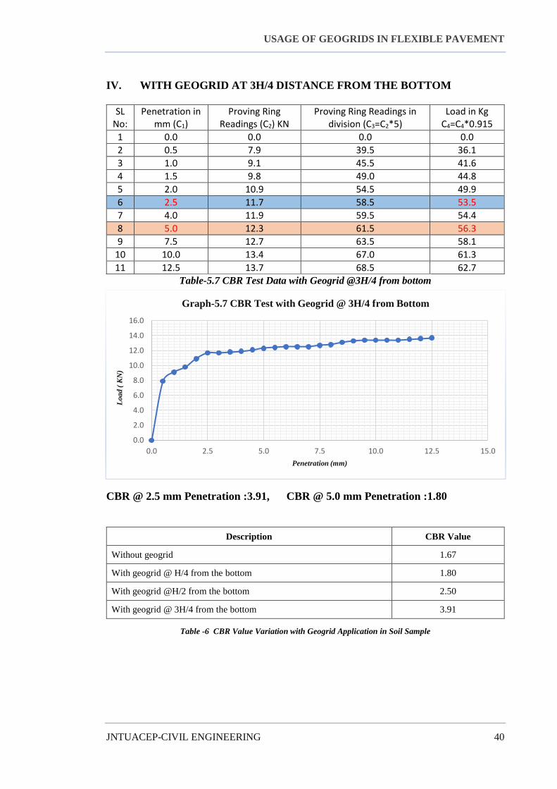
IV. WITH GEOGRID AT 3H/4 DISTANCE FROM THE BOTTOM
SL No:
Penetration in mm (C1)
Proving Ring Readings (C2) KN
Proving Ring Readings in division (C3=C2*5)
Load in Kg C4=C4*0.915
1 0.0 0.0 0.0 0.0
2 0.5 7.9 39.5 36.1
3 1.0 9.1 45.5 41.6
4 1.5 9.8 49.0 44.8
5 2.0 10.9 54.5 49.9
6 2.5 11.7 58.5 53.5
7 4.0 11.9 59.5 54.4
8 5.0 12.3 61.5 56.3
9 7.5 12.7 63.5 58.1
10 10.0 13.4 67.0 61.3
11 12.5 13.7 68.5 62.7
Table-5.7 CBR Test Data with Geogrid @3H/4 from bottom
CBR @ 2.5 mm Penetration :3.91, CBR @ 5.0 mm Penetration :1.80
Table -6 CBR Value Variation with Geogrid Application in Soil Sample
Description CBR Value
Without geogrid 1.67
With geogrid @ H/4 from the bottom 1.80
With geogrid @H/2 from the bottom 2.50
With geogrid @ 3H/4 from the bottom 3.91
0.0
2.0
4.0
6.0
8.0
10.0
12.0
14.0
16.0
0.0 2.5 5.0 7.5 10.0 12.5 15.0
Lo
ad
( K
N)
Penetration (mm)
Graph-5.7 CBR Test with Geogrid @ 3H/4 from Bottom
USAGE OF GEOGRIDS IN FLEXIBLE PAVEMENT
JNTUACEP-CIVIL ENGINEERING 41
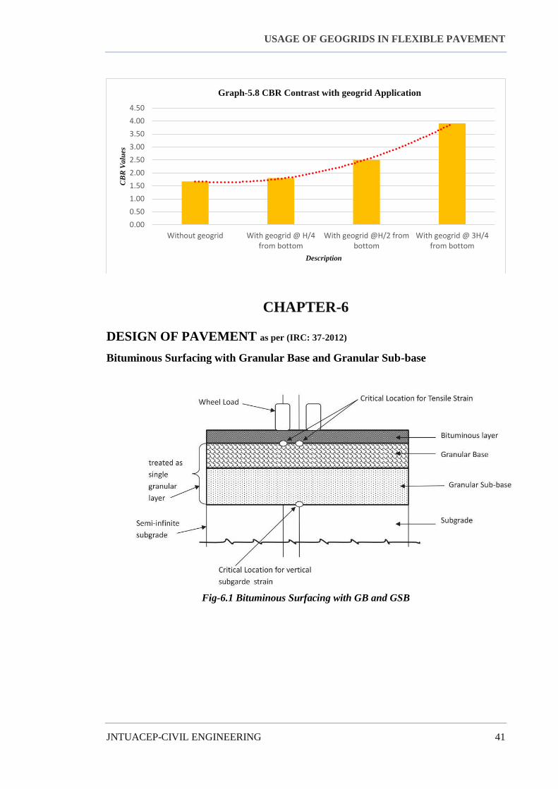
CHAPTER-6
DESIGN OF PAVEMENT as per (IRC: 37-2012)
Bituminous Surfacing with Granular Base and Granular Sub-base
Fig-6.1 Bituminous Surfacing with GB and GSB
0.00
0.50
1.00
1.50
2.00
2.50
3.00
3.50
4.00
4.50
Without geogrid With geogrid @ H/4from bottom
With geogrid @H/2 frombottom
With geogrid @ 3H/4from bottom
CB
R V
alu
es
Description
Graph-5.8 CBR Contrast with geogrid Application

USAGE OF GEOGRIDS IN FLEXIBLE PAVEMENT
JNTUACEP-CIVIL ENGINEERING 42
IRC: 37-2012
Graph-6.1 Plate-2 (IRC:37-2012) Pavement Design Catalogues
WITHOUT GEOGRID: CBR: 1.67 %, N: 47.45 msa ≈ 50 msa
i.e., not fit for laying a road directly on the Subgrade soil; which needs Stabilization to it.
WITH GEOGRID AT 3H/4 FROM BOTTOM: CBR: 3.91 %, N: 47.45 msa ≈ 50 msa
i.e., the thickness of GSB: 300 mm, G. Base:250, DBM: 115 mm, BC/SDBC:40mm
Where; GSB: Granular Sub-base, G. Base: Granular Base, DBM: Dense Bituminous
Macadam, BC: Bituminous Concrete, SDBC: Semi-Dense Bituminous Concrete.
The thickness of pavement required in MM:
Table-6.1 Thickness of Pavement in mm contrast with the application of geogrid
Thickness Without grid With Geogrid @ H/4 from bottom
GSB NA 300
G.BASE NA 250
DBM NA 115
BC NA 40
Total NA 705

USAGE OF GEOGRIDS IN FLEXIBLE PAVEMENT
JNTUACEP-CIVIL ENGINEERING 43
CHAPTER-7
CONCLUSION AND RECOMMENDATIONS
The positive effects of geogrid reinforced subgrade courses can economically and
ecologically be utilized to reduce aggregate thickness. And it can also increase the life of
the pavement and can also decrease the overall cost of the pavement construction with an
increased lifetime.
The study investigated the application of geogrids to subgrade material as a form
of reinforcement to road construction. The inclusion of the geo-grid considerably
increases the strength of poor soils, which is reflected in the higher CBR values. The
study shows that the strength of the subgrade is significantly altered positively by the
positioning of the geo-grid at varying depth. It was observed that the highest subgrade
strength is achieved when it is placed at 3H/4 for a single layer although has a satisfactory
result at H/2 and H/4 respectively. On reinforcing the soil, there is a considerable increase
in performance of the subgrade in the unsoaked condition. The use of geogrids as
reinforcement to poor soils improves its strength. It is non-bio degradable and therefore
durable; it also increases the ultimate service life of the pavement. The use of Geogrids
should, therefore, be encouraged as an effective and modern form of improving road
construction on poor sub-grade materials. Further research should be analyzed in
ascertaining the effect of geogrids on subgrade soils under the unsoaked condition

USAGE OF GEOGRIDS IN FLEXIBLE PAVEMENT
JNTUACEP-CIVIL ENGINEERING 44
FUTURE SCOPE
From above discussion, it can be said that geogrids may serve better even on
soaked conditions too. We have collected traffic data only for two-lane two-way traffic
It can be applicable to more lanes also. It can be applicable for plain, rolling, hilly and
steep roads also. For any industrial region where the traffic is high, it is suggested to place
more than a single layer of geogrid.

USAGE OF GEOGRIDS IN FLEXIBLE PAVEMENT
JNTUACEP-CIVIL ENGINEERING 45
REFERENCES
1. IRC:37-2012 Guidelines for DESIGN OF FLEXIBLE PAVEMENTS
2. Soil Mechanics and Foundation Engineering By DR.K.R. ARORA
3. Rankilor, P. R., Membranes in Ground Engineering, John Wiley and Sons, New
York, 1981.
4. I.S: 2720 (Part – XVI), 1979: Indian Standard Methods of test for Soils, Laboratory
Determination of CBR.
5. Mehndiratta H.C (1993) Chandra Satish, Sirsh Virendra “Correlations amongst
strength parameters of soil reinforced with geotextile” HRB No 49, Indian Roads
Congress, 13-24.
6. R. M. Koerner, “Designing with Geosynthetics: Volume 1,” 2005. [Online].
Available: Amazon.com [Accessed 2 June 2014].
7. A. C. Lopes, “Definition of Geosynthetics: Geosynthetics in engineering,” 2008.
[Online]. Available: http://www.woodhead.com/geosynthetics/[Accessd 2 March
2014].
8. D. T. Bergado, and H. M. Abuel-Naga, “Tsunami devastations and reconstruction
with Geosynthetics,” 2005. [Online]. Available: http://www.freelibrary.com
[Accessed 2 March 2014].
9. A. Olawale, “Use of geosynthetics in road construction,” Department of Civil
Engineering, Federal University of Technology, 2011. [Online]. Available:
http://www.google. com/google books.
10. Motanelli, F., Zhao, A., and Rimoldi, P., 1997, Geosynthetics-reinforced pavement
system: testing and design., Proceedings of Geosynthetics, 97, 549-604.
11. Kumar, P. S., and Rajkumar, R., 2012, Effect of geotextile on CBR strength of
unpaved road with soft subgrade.,Electronic Journal of Geotechnical
Engineering(EJGE), 17, 1355 – 1363.
12. Ministry of Roads and Highway, “Technical specification for roads and bridges,”
Republic of Ghana, 2006