Embed Size (px)
Citation preview

THE USE OF GEOGRIDS ON MAINLINE AND INTERMODAL
FACILITY PROJECTS
Jim Penman C.Geol
Site Development Consultant
3274 Chipping Wood Court, Alpharetta GA 30004
Phone: 404-368-0052
e-mail: [email protected]
September 2011
Word Count: 3,754 words +13 figures/tables (3,250 words) = 7,004 equivalent words
© 2011 AREMA ®

ABSTRACT
The inclusion of geogrid reinforcement within the sub-ballast and ballast layers of roadbed structures has
gained widespread acceptance in many parts of the world. Used successfully on projects for more than
20 years, the national rail authorities in several countries have gone so far as to provide formal guidance
on the use of these products in their own design codes.
In contrast, widespread use of geogrid technology in North America has been much slower; it would
appear however that things are starting to change. Following the recent publication of a new chapter in
the AREMA Manual for Railway Engineering (AREMA, 2010) geogrids are now formally recognized in the
US and Canadian rail markets. In addition, the use of geogrids has gained significant momentum,
particularly during the last five years, as a result of their more frequent use on a larger number of heavy
freight and lighter passenger rail projects in the North America.
The paper provides a detailed review of the extensive laboratory and full-scale testing used to quantify
the performance benefits associated with the use of geogrids in roadbed structures (ballast life extension,
and roadbed thickness reduction). A set of brief case studies is used to highlight how geogrid technology
has been put into practice both in North America and further afield. The paper also describes several
intermodal yard projects where geogrids have been used to provide similar benefits for the construction of
heavy duty pavements.
INTRODUCTION TO MECHANICAL REINFORCEMENT
Koerner (1998) defined a geogrid as “a geosynthetic material consisting of connected parallel sets of
tensile ribs with apertures of sufficient size to allow strike-through of surrounding soil, stone or other
geotechnical material”. Mechanical reinforcement is a term commonly used to describe the manner by
which geogrids interact with the surrounding soil; in rail applications the soil concerned is typically an
unbound granular material.
© 2011 AREMA ®

When unbound aggregate is placed on top of a geogrid, the coarser particles partially penetrate through
the apertures and lock into position (Figure 1). This effect commonly referred to as “mechanical interlock”,
leads to lateral confinement of the unbound aggregate and a general stiffening of the layer. Because of
the way a geogrid interacts with surrounding soil, it is often referred to as “the re-bar within an unbound
aggregate layer”.
Figure 1: Mechanical interlock resulting from partial penetration of aggregate particles
The same process takes place when a geogrid is used to reinforce an aggregate layer that forms part of
rigid and flexible pavement structures typically found within intermodal facilities and other
loading/unloading facilities.
© 2011 AREMA ®

GEOGRID TECHNOLOGY IN RAIL APPLICATIONS
Ballast and Sub-ballast Reinforcement
The confining effect of a geogrid is important in roadbed reinforcement applications as lateral movement
of granular particles is a major cause of sub-ballast and ballast settlement. However, the layer stiffening
effect is also important, particularly when construction takes place on less competent subgrades (stiff clay
or worse). Under these circumstances, the stiffer aggregate distributes loads more efficiently onto the
underlying soil, thereby reducing both the dynamic movement (vertical track deflection during a single
load cycle) and longer-term settlement of the roadbed due to subgrade consolidation.
There are two locations within a roadbed structure where geogrids are typically used. When placed at the
bottom of the sub-ballast layer, the principle function of the geogrid is to distribute the imposed dynamic
and static loads over a wider area thereby reducing the pressure imposed on the underlying subgrade. In
adopting this approach, the designer has two options:
1. Increase the factor of safety for a given roadbed section
2. Maintain the current factor of safety but decrease the required thickness of the ballast and/or
sub-ballast layers
To illustrate how these two options can be used in practice, a set of roadbed sections is provided in
Figure 2 for a given set of design parameters.
© 2011 AREMA ®
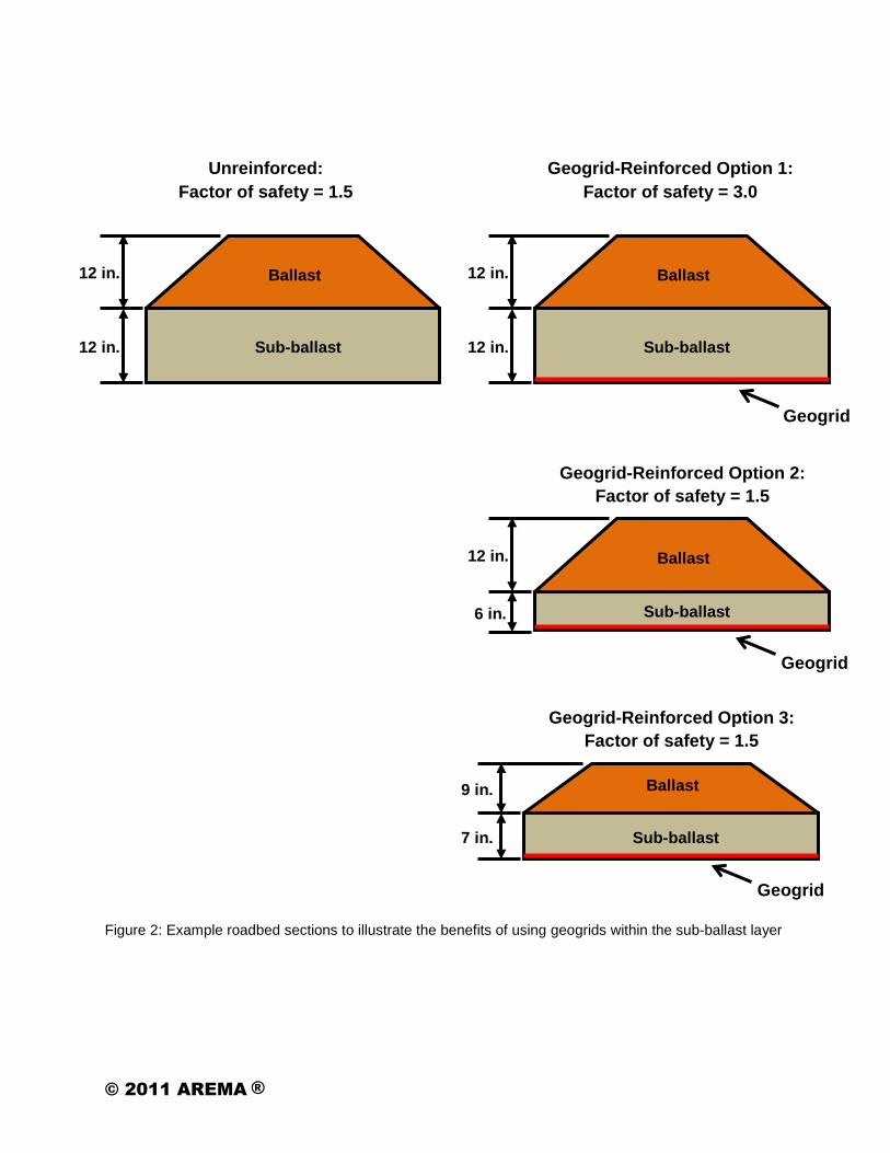
Figure 2: Example roadbed sections to illustrate the benefits of using geogrids within the sub-ballast layer
12 in.
12 in.
Sub-ballast
Ballast
Unreinforced: Factor of safety = 1.5
7 in.
9 in.
Sub-ballast
Ballast
Geogrid-Reinforced Option 3: Factor of safety = 1.5
Geogrid
6 in.
12 in.
Sub-ballast
Ballast
Geogrid-Reinforced Option 2: Factor of safety = 1.5
Geogrid
12 in.
12 in.
Sub-ballast
Ballast
Geogrid-Reinforced Option 1: Factor of safety = 3.0
Geogrid
© 2011 AREMA ®

Several of the Class 1 rail companies in the US are regular users of geogrids. Typically these products
are used in areas when soft subgrades are encountered and the rail company’s standard roadbed section
considered inappropriate for these conditions. The standard section is effectively “beefed up” by placing a
geogrid at the bottom of the sub-ballast layer. Although no formal analysis and design is generally
undertaken, this procedure is effectively the same as that highlighted in “Geogrid-Reinforced Option 1”
above.
Pavement Structures within Intermodal and General Loading/Unloading Facilities
Some of the larger lifting vehicles used within intermodal and general loading/unloading facilities generate
axle loads over 200 kips. When these loads are compared with the 18 kip to 20 kip loads typical for
conventional highway trucks, there is clearly a substantial difference in load magnitude. Pavement
structures built to carry these loads tend therefore to be substantial even when the underlying subgrade is
relatively competent. When a geogrid is used to reinforce the granular layer within these heavy pavement
structures, a significant reduction in the thickness of the granular layer and/or overlying asphalt/concrete
layer(s) can be achieved. When pavement material savings, cost of installation and cost of the geogrid
are balanced, total construction savings in excess of 10% can be generated. In the event that a weak
subgrade is encountered (CBR < 1.5%), the savings are typically much greater.
Two examples of pavement sections where geogrids were used to reduce material costs are presented in
Figures 3 and 4.
© 2011 AREMA ®

Figure 3: Rigid pavement sections with and without geogrid reinforcement
Figure 4: Flexible pavement section with and without geogrid reinforcement
Roller Compacted
Concrete (RCC)
Aggregate Base
17 in.
6 in.
Unreinforced
Roller Compacted
Concrete (RCC)
Aggregate Base
14 in.
16 in.
Geogrid-Reinforced
Asphalt Concrete
Aggregate Base
18 in.
18 in.
Asphalt Concrete
Aggregate Base
25 in.
6 in.
Unreinforced Geogrid-Reinforced
Geogrid
Geogrid
© 2011 AREMA ®

In both examples above, the pavements were constructed on a competent subgrade. When this is not the
case, there is often the need to increase the thickness of the aggregate layer or incorporate some sort of
subgrade improvement measures – over-excavation and removal of the soft layer, chemical stabilization,
etc. Under these circumstances, an additional geogrid-reinforced aggregate layer can be used. In most
cases the cost savings associated with the use of a geogrid in this manner can be upwards of 40%.
GEOGRID RESEARCH
The earliest research undertaken to quantify the benefits of using geogrids in roadbed structures was
carried out at Queen’s University in Kingston, Ontario by Bathurst and Raymond (1987). An artificial
subgrade consisting of a series of rubber bonded cork mats was placed at the bottom of a rigid test box;
the remainder of the box was filled with ballast. Cyclic loads generated by a hydraulic actuator were
applied to a cross-tie placed on the surface of the ballast.
The results of the testing (Figure 5) illustrated how, for a maximum permanent settlement limit of 25 mm
(1 in.), the inclusion of a geogrid within the roadbed structure extended its service life. An almost 5-fold
increase was observed for cases where a reasonably competent subgrade (39% CBR) was used and
also where a soft subgrade condition existed (1% CBR).
Figure 5: Results of testing undertaken at Queens University, Ontario, Canada
© 2011 AREMA ®

In a further study reported by Matharu (1994), a set of full-scale tests were undertaken at the Network
Rail (previously called British Rail) test facility located in Derby, England (Figure 6).
Figure 6: Network Rail full-scale test facility and results for reinforced and unreinforced roadbeds
The main results from the study (also Figure 6) effectively show that when a roadbed structure reinforced
with a geogrid is constructed on top of a soft subgrade, its rate of settlement approaches that for the
same roadbed structure constructed on bedrock. In addition, on soft subgrade soils and for the same
roadbed thickness, the dynamic vertical movement of the track as the wheel of the train passes is
reduced by approximately 40% when a geogrid is used to reinforce the roadbed (Figure 7).
Figure 7: Dynamic vertical movement occurring for roadbeds constructed on soft subgrades
© 2011 AREMA ®

A rail corridor constructed between Hochstadt and Probstzella in Germany presented an opportunity to
observe the benefits of using geogrids in a full-scale field situation. Plate bearing tests undertaken by the
German National Rail Authority (Deutsche Bahn) demonstrated that the stiffness of a geogrid-reinforced
400 mm (16 in.) thick sub-ballast was approximately the same as a 600 mm (24 in.) thick unreinforced
layer. Also, the stiffness of both 400 mm (16 in.) and 600 mm (24 in.) unreinforced sections doubled when
a geogrid was included (Figure 8).
Figure 8: In-situ performance testing of roadbed sections constructed on a main line project in Germany
On a similar project constructed near Cologne, Germany, the inclusion of a geogrid within a roadbed
constructed over a soft formation allowed the sub-ballast to be reduced from 1050 mm (42 in.) to 700 mm
(28 in.). Despite the thickness reduction, the target modulus of 120 MPa (17,400 psi) was maintained.
On a mainline project in Nagykanizsa, Hungary, the decision was made to include a geogrid within the
ballast layer during a rehabilitation operation. Prior to replacement of the existing roadbed, the rail line
required monthly re-surfacing. The dynamic deflection of the rail track was measured using a rail car, both
prior to and following the inclusion of the geogrid within the roadbed section (Figure 9). The data obtained
clearly demonstrates that the inclusion of a geogrid resulted in a dramatic reduction in the dynamic
deflection taking place during trafficking. Service disruptions due to the requirement for frequent
maintenance have since been eliminated.
© 2011 AREMA ®

Figure 9: Performance testing undertaken on a mainline project in Hungary
RECOGNITION OF GEOGRID BENEFITS BY PUBLIC AUTHORITIES
The performance benefits highlighted above have been recognized by several public and private
authorities. Brief details of the guidance developed by three such authorities are provided in the
remainder of this section.
Network Rail, United Kingdom
The National Rail Authority In the United Kingdom (Network Rail, formerly known as British Rail) has used
geogrids beneath their mainline tracks since the early 1990’s. In addition, the company has carried out
several in-house testing programs, both in the laboratory and along in-service tracks. Based on the
results of this testing Network Rail has quantified the performance benefits associated with the use of
geogrids in roadbed structures.
Design protocols for roadbed structures are prescribed in Network Rail (2005). The general approach
adopted is to attain a pre-determined target stiffness for the roadbed structure itself. As shown in Table 1,
the target value varies depending on whether a geogrid is included within the roadbed structure or not – a
minimum dynamic sleeper (cross-tie) support stiffness (K) of 60 kN/mm is required for an unreinforced
roadbed, whereas only 30 kN/mm is required for the same acceptable level of performance when a
geogrid is included within the roadbed section.
© 2011 AREMA ®

Track Condition
Minimum Dynamic Sleeper Support
Stiffness, K (kN/mm/sleeper end)
Absolute Value 30
Existing Main Lines With Geogrid Reinforcement 30
Without Geogrid Reinforcement 60
New Track Up to 100 mph 60
Above 100 mph 100
Table 1: Required roadbed stiffness based on Network Rail design protocols
For a given set of subgrade conditions and the same type of aggregate, the stiffness of a roadbed section
is essentially a function of the combined thickness of the ballast and sub-ballast layers. The design chart
shown in Figure 10 illustrates that the use of a geogrid results in a roadbed thickness reduction of around
200 mm. (8 in ) relative to a conventional unreinforced section.
Figure 10: Roadbed design chart provided by Network Rail, UK
© 2011 AREMA ®

It should be appreciated that although the Network Rail design protocols refer to geogrids generically
(i.e. no specific manufacturer’s products are called out), any geogrid product proposed for use on their rail
system requires a current PADS Certificate. This document is obtained from Network Rail and is only
issued for products where the performance benefits outlined above have been demonstrated in full-scale
laboratory and field tests.
National Rail Authority (SZDC), Czech Republic
The use of geogrids within roadbed sections gathered significant momentum in Eastern Europe during
the period locally known as “The Velvet Revolution”; this term describes the overthrow of the old
communist government within what was then called Czechoslovakia. One of the immediate needs during
this period was to bring Czech railways up to the same standards as the rail structures used in Western
Europe. The need to minimize costs was however a main concern. This prompted the Czech Rail
Authority (SZDC) to consider adopting some of the latest construction techniques available.
The use of geogrids within the roadbed structure was considered at this time to be innovative technology.
However, their use in recent years has become commonplace and was marked by a recent publication
(SZDC, 2010). This document was developed following several years of discussion and performance
testing undertaken at the Technical University of Prague. The guidance in this document essentially
provides the rail designer with protocols for the incorporation of a set of specific geogrid products.
American Railroad Engineering and Maintenance of Way Association (AREMA), USA
The premier reference document for the design of rail structures in the US is provided by AREMA (2010).
Within Chapter 1, Section 11 of this document guidance is provided on the use of geogrids within a
roadbed structure. Section 11 was developed following a thorough review of the performance testing
described above along with numerous projects constructed using these techniques over the last 25 years.
© 2011 AREMA ®
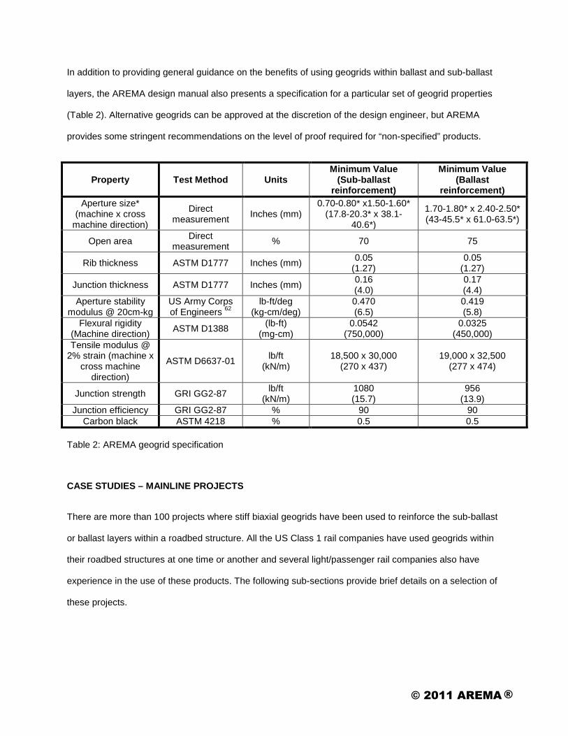
In addition to providing general guidance on the benefits of using geogrids within ballast and sub-ballast
layers, the AREMA design manual also presents a specification for a particular set of geogrid properties
(Table 2). Alternative geogrids can be approved at the discretion of the design engineer, but AREMA
provides some stringent recommendations on the level of proof required for “non-specified” products.
Property Test Method Units Minimum Value
(Sub-ballast reinforcement)
Minimum Value (Ballast
reinforcement) Aperture size*
(machine x cross machine direction)
Direct measurement Inches (mm)
0.70-0.80* x1.50-1.60* (17.8-20.3* x 38.1-
40.6*)
1.70-1.80* x 2.40-2.50* (43-45.5* x 61.0-63.5*)
Open area Direct measurement % 70 75
Rib thickness ASTM D1777 Inches (mm) 0.05 (1.27)
0.05 (1.27)
Junction thickness ASTM D1777 Inches (mm) 0.16 (4.0)
0.17 (4.4)
Aperture stability modulus @ 20cm-kg
US Army Corps of Engineers 62
lb-ft/deg (kg-cm/deg)
0.470 (6.5)
0.419 (5.8)
Flexural rigidity (Machine direction) ASTM D1388 (lb-ft)
(mg-cm) 0.0542
(750,000) 0.0325
(450,000) Tensile modulus @
2% strain (machine x cross machine
direction)
ASTM D6637-01 lb/ft (kN/m)
18,500 x 30,000 (270 x 437)
19,000 x 32,500 (277 x 474)
Junction strength GRI GG2-87 lb/ft (kN/m)
1080 (15.7)
956 (13.9)
Junction efficiency GRI GG2-87 % 90 90 Carbon black ASTM 4218 % 0.5 0.5
Table 2: AREMA geogrid specification
CASE STUDIES – MAINLINE PROJECTS
There are more than 100 projects where stiff biaxial geogrids have been used to reinforce the sub-ballast
or ballast layers within a roadbed structure. All the US Class 1 rail companies have used geogrids within
their roadbed structures at one time or another and several light/passenger rail companies also have
experience in the use of these products. The following sub-sections provide brief details on a selection of
these projects.
© 2011 AREMA ®

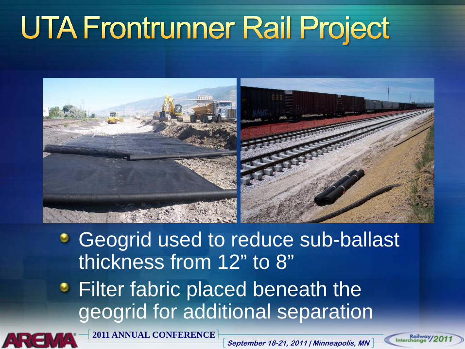
Utah Transit Authority (UTA) Light Rail Project, Salt Lake City, Utah (2005-2008)
The UTA’s FrontRunner commuter rail line runs 44 miles from the city of Ogden in Weber County south to
Salt Lake City. The line is located in an existing right-of-way that runs parallel with the Wasatch
Mountains. The area is part of a natural drainage basin, characterized by poor quality soils and shallow
groundwater. The subgrade beneath the roadbed typically consists of low to medium strength cohesive
soils and loose to dense sand.
A conventional roadbed design which incorporated a thicker sub-ballast layer, proved cost prohibitive due
to the extremely high cost associated with the sourcing of local aggregate. Calculations determined that
the required sub-ballast thickness could be reduced conservatively from 12 in. to 8 in. by including a layer
of geogrid at the interface between the sub-ballast and the underlying subgrade. Reducing the sub-ballast
depth provided significant cost savings and expedited the construction process – less aggregate could be
placed in less time. In addition, this approach eliminated contact with the shallow groundwater and for a
900 ft length of track, eliminated the need to relocate an existing set of buried utilities.
Dallas Area Rapid Transit Authority (DART), NW1A Rail Section, Dallas, Texas (2003-2008)
DART has been a regular user of geogrids within their roadbed structures since 2003. Traditionally, prior
to constructing their standard section, the underlying cohesive soils would be mixed with lime to a depth
of 6 in. Although it provided good short-term support for the roadbed, this approach resulted in some
logistical problems.
Installation of the lime stabilization was not well suited for the project due to the generation of extensive
dust clouds in what was an urban location. Additionally, installation process for lime stabilization requires
dry, mild conditions; when the local weather does not comply, construction work on the project is
temporarily suspended. Finally, protruding utility pipes were present at the time the roadbed was
constructed. As large vehicles are required to install the lime, this would have made things very difficult
for the contractor and slowed down the construction process significantly.
© 2011 AREMA ®

In order to provide an alternate solution to the lime stabilization, a structural analysis was undertaken to
demonstrate that installation of the 6 in. thick layer of lime could be avoided by including a layer of
geogrid at the bottom of the standard roadbed section. Installation adopting this “mechanical stabilization”
technique was both simple and fast, requiring only minor slitting of the geogrid in the areas where the
protruding utilities were located.
Kansas City Southern (KCS) Rail Company, Victoria to Rosenberg Line, Texas (2008)
During 2008 and early 2009, KCS undertook the reconstruction of a 91 mile section of disused track in
south Texas. Where weaker subgrades were encountered or the original sub-ballast had been removed
or washed out, normal construction methods required placement of up to 12 in. of new sub-ballast.
Instead, a geogrid was placed at the bottom of the new sub-ballast in order to reduce the required
thickness to only 6 in.
In the absence of any local suppliers, aggregate was transported in from quarries in Hatton, AR and
Mexico resulting in a particularly high cost for the sub-ballast layer. On this project, reducing the required
sub-ballast thickness resulted in significant construction cost savings. In total, approximately
237,000 SY of geogrid was installed.
CASE STUDIES – INTERMODAL YARDS
CSX Intermodal Yard, Chicago, Illinois (1998)
Close to 700 semi-tractor trailers with a maximum weight of 80,000 lbs (350 kN) roll in and out of this
facility each day. In addition, the pavements in the northern area of the facility are required to withstand
the pressures imposed by straddle cranes that weigh 180,000 lbs (800 kN) and have a loading capacity of
100,000 lbs (445 kN). The facility is open for business 24/7 throughout the year and the pavements are
thus subjected to Chicago’s blistering summer days and bitter winters.
© 2011 AREMA ®

A number of options were considered for increasing the bearing capacity of the site’s underlying soils; in
the end, a geogrid solution was selected. Ultimately two layers of geogrid were used to reinforce the
unbound aggregate layer. In using a geogrid system, CSX were able to save almost 30% on the cost of
their flexible pavement when compared with a rigid pavement solution.
Canadian Pacific Rail (CPR) Project – Detroit, Michigan (1987)
This project was designed by CPR Engineers at their head office in Calgary, Alberta. The site was
underlain by soft soils which resulted in the requirement for a thick pavement section. The client was
interested in using mechanical reinforcement to reduce the thickness of the base course layer thus
leading to cost savings and a reduction in the time required for construction activities. A single layer of
geogrid was used to reinforce the base aggregate within the main pavement section, thus reducing the
required thickness of this layer. The actual pavement section constructed to carry the heavy axle loads
characteristic for this facility is illustrated in Figure 11.
Figure 11: Pavement section at Canadian Pacific Rail Intermodal Facility, Detroit, Michigan
Asphalt Concrete
Aggregate Base
4 in.
6 in.
Geogrid
Separation Geotextile
8 in.
12 in.
Aggregate Base
Sub-base
© 2011 AREMA ®

ACKNOWLEDGEMENT
The author wishes to acknowledge the support provided by the Tensar International Corporation (TIC) in
the production of this paper. In particular, it is recognized that several of the images presented in this
paper comprise intellectual property owned by TIC. These images are included with the full approval of
TIC.
REFERENCES
AREMA (2010) Manual for Railway Engineering American Railroad Engineering and Maintenance-of-Way Association Bathurst, R.J and Raymond, G.P. (1987) Geogrid Reinforcement of Ballasted Track Transportation Research Board 66th Annual Meeting Koerner, R.M. (1998) Designing with Geosynthetics, fourth edition. Prentice Hall, Upper Saddle River, NJ. Matharu, M. (1994) Geogrids Cut Ballast Settlement Rate on Soft Substructures. Railway Gazette International, March 1994. Network Rail (2005) Formation Treatments. Business Process Document NR/SP/TRK/9039. SZDC (2010) Tecnike Podminski Dodaci (Technical Conditions of Delivery) Reference Document 013/2010 Geomat Správa železnični dopravni cesty
© 2011 AREMA ®

TABLES AND FIGURES
Table 1: Required roadbed stiffness based on Network Rail design protocols
Table 2: AREMA geogrid specification
Figure 1: Mechanical interlock resulting from partial penetration of aggregate particles
Figure 2: Example roadbed sections to illustrate the benefits of using geogrids within the sub-ballast layer
Figure 3: Rigid pavement sections with and without geogrid reinforcement
Figure 4: Flexible pavement section with and without geogrid reinforcement
Figure 5: Results of testing undertaken at Queens University, ON, Canada
Figure 6: Network Rail full-scale test facility and results for reinforced and unreinforced roadbeds
Figure 7: Dynamic vertical movement occurring for roadbeds constructed on soft subgrade
Figure 8: In-situ performance testing of roadbed sections constructed on a main line project in Germany
Figure 9: Performance testing undertaken on mainline project in Hungary
Figure 10: Roadbed design chart provided by Network Rail, UK
Figure 11: Pavement section at Canadian Pacific Rail Intermodal Facility, Detroit, Michigan
© 2011 AREMA ®

2011 ANNUAL CONFERENCESeptember 18-21, 2011 | Minneapolis, MN
Jim PenmanSite Solutions ConsultantAlpharetta, GA

2011 ANNUAL CONFERENCESeptember 18-21, 2011 | Minneapolis, MN
Introduction to mechanical reinforcementBallast and sub-ballast reinforcementHeavy duty pavement structuresGeogrid researchCase studies
2011 ANNUAL CONFERENCESeptember 18-21, 2011 | Minneapolis, MN

2011 ANNUAL CONFERENCESeptember 18-21, 2011 | Minneapolis, MN

2011 ANNUAL CONFERENCESeptember 18-21, 2011 | Minneapolis, MN
Supplied in rolls; 9 ft, 13 ft, 15 ft wideAggregate compacted on geogridMinimum aggregate thickness 6 in.

2011 ANNUAL CONFERENCESeptember 18-21, 2011 | Minneapolis, MN

2011 ANNUAL CONFERENCESeptember 18-21, 2011 | Minneapolis, MN
Geogrid placed at bottom of ballast –maintenance reduction solution
Geogrid placed at bottom of sub-ballast –improved bearing capacity solution

2011 ANNUAL CONFERENCESeptember 18-21, 2011 | Minneapolis, MN
2011 ANNUAL CONFERENCESeptember 18-21, 2011 | Minneapolis, MN
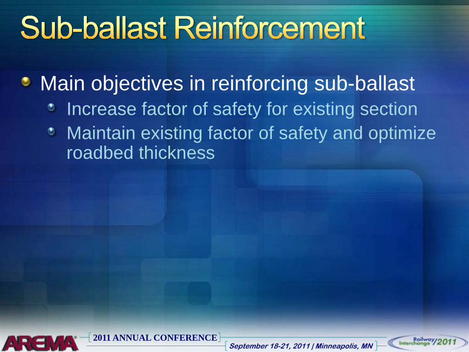
Main objectives in reinforcing sub-ballastIncrease factor of safety for existing sectionMaintain existing factor of safety and optimize roadbed thickness

2011 ANNUAL CONFERENCESeptember 18-21, 2011 | Minneapolis, MN
12 in.
12 in.
Ballast
Sub-ballast
Unreinforced: FoS = 1.5
12 in.
12 in.
Ballast
Sub-ballast
Reinforced: FoS = 3.0
9 in.
7 in.
Ballast
Sub-ballast
Reinforced: FoS = 1.5
12 in.
6 in.
Ballast
Sub-ballast
Reinforced: FoS = 1.5

2011 ANNUAL CONFERENCESeptember 18-21, 2011 | Minneapolis, MN

2011 ANNUAL CONFERENCESeptember 18-21, 2011 | Minneapolis, MN
Predominantly used to increase the period between maintenance events
2011 ANNUAL CONFERENCESeptember 18-21, 2011 | Minneapolis, MN

2011 ANNUAL CONFERENCESeptember 18-21, 2011 | Minneapolis, MN
Soft subgrade
Critical Mechanism –subgrade failure or deformationPrinciple benefits:
Cost savings (50%)Faster construction

2011 ANNUAL CONFERENCESeptember 18-21, 2011 | Minneapolis, MN
Critical Failure Mechanism – lateral movement of aggregate particles
Principle benefits:Initial cost savings –generally 10% to 20%Extended design life –3 to 6 times

2011 ANNUAL CONFERENCESeptember 18-21, 2011 | Minneapolis, MN
Cost analysis data:Area - ¼ mile x ¼ mileAsphalt cost - $75/ton (installed)Aggregate cost - $15/ton (installed)Undercut cost - $5/CY

2011 ANNUAL CONFERENCESeptember 18-21, 2011 | Minneapolis, MN
7” AC
17” Crushed Aggregate
6” AC
14” Crushed Aggregate
Geogrid
Cost: $44.27/SY Cost: $41.88/SY
Total saving: $462,000

2011 ANNUAL CONFERENCESeptember 18-21, 2011 | Minneapolis, MN
13” AC
9” AC
8” Crushed Aggregate
Tensar TX170 Geogrid
Cost: $51.18/SY Cost: $47.79/SY
Total saving: $655,000

2011 ANNUAL CONFERENCESeptember 18-21, 2011 | Minneapolis, MN
Network Rail FacilityDerby, UK

2011 ANNUAL CONFERENCESeptember 18-21, 2011 | Minneapolis, MN
Network Rail Test FacilityDerby, UK

2011 ANNUAL CONFERENCESeptember 18-21, 2011 | Minneapolis, MN
Network Rail Test Facility, Derby, UK

2011 ANNUAL CONFERENCESeptember 18-21, 2011 | Minneapolis, MN
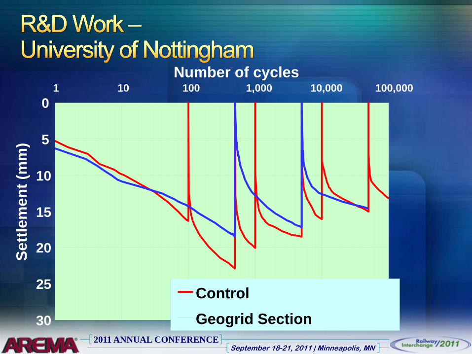
Composite Element Test (CET)University of NottinghamNottingham, UK

2011 ANNUAL CONFERENCESeptember 18-21, 2011 | Minneapolis, MN
Composite Element Test (CET)
2011 ANNUAL CONFERENCESeptember 18-21, 2011 | Minneapolis, MN
Investigating interval between tamping
0
5
10
15
20
25
30
1 10 100 1,000 10,000 100,000Number of cycles
Settl
emen
t (m
m)
ControlGeogrid Section

2011 ANNUAL CONFERENCESeptember 18-21, 2011 | Minneapolis, MN
University of NottinghamNottingham, UK

2011 ANNUAL CONFERENCESeptember 18-21, 2011 | Minneapolis, MN

2011 ANNUAL CONFERENCESeptember 18-21, 2011 | Minneapolis, MN

2011 ANNUAL CONFERENCESeptember 18-21, 2011 | Minneapolis, MN

2011 ANNUAL CONFERENCESeptember 18-21, 2011 | Minneapolis, MN

2011 ANNUAL CONFERENCESeptember 18-21, 2011 | Minneapolis, MN
No. passes:Unreinforced = 300,000Reinforced = 750,0002.5 fold increase
0
2
4
6
8
10
12
14
0 200,000 400,000 600,000 800,000 1,000,000Number of cycles
Settl
emen
t (m
m)
ControlSSLA307.5 mm settlement
No. passes:Unreinforced = 350,000Reinforced = 1,000,000Almost 3 fold increase

2011 ANNUAL CONFERENCESeptember 18-21, 2011 | Minneapolis, MN
After 1 million cycles the geogrid was exhumed
QC strength measured
No significant damage due to loading

2011 ANNUAL CONFERENCESeptember 18-21, 2011 | Minneapolis, MN
Network Rail StudyCoppul Moor, UK

2011 ANNUAL CONFERENCESeptember 18-21, 2011 | Minneapolis, MN
Reconstruction on UK main line
Investigation of deformation before and after installation of reinforcement

2011 ANNUAL CONFERENCESeptember 18-21, 2011 | Minneapolis, MN
0
1
2
3
456
7
8
9
10
1995 1996 1997 1998 1999 2000 2001 2002 2003 2004 2005 2006 2007Year
SD o
ver 3
5m (m
m)
Deformation0.9 mm/yr0.25 mm/yr
Geogridinstalled
Ch 10 miles 220 yds to 440 yds
Increase in ballast life:= 0.9/0.25 = 3.6

2011 ANNUAL CONFERENCESeptember 18-21, 2011 | Minneapolis, MN
0
1
2
3
456
7
8
9
10
1995 1996 1997 1998 1999 2000 2001 2002 2003 2004 2005 2006 2007Year
SD o
ver 3
5m (m
m)
Deformation1.43 mm/yr0.4 mm/yr Ch 10 miles 440 yds to 660 yds
Geogridinstalled
Increase in ballast life:= 1.43/0.4 = 3.6

2011 ANNUAL CONFERENCESeptember 18-21, 2011 | Minneapolis, MN

2011 ANNUAL CONFERENCESeptember 18-21, 2011 | Minneapolis, MN
Approximate costs for:Track surfacing: $18,000/mileGeogrid cost: $27,000/mile (installed)
Need to extend existing ballasting period by factor of 1.5 for economyResults from research studies:
Queens University study: Factor = 4.8Nottingham University study: Factor = 3.0Coppull Moor in service study: Factor = 3.6

2011 ANNUAL CONFERENCESeptember 18-21, 2011 | Minneapolis, MN

2011 ANNUAL CONFERENCESeptember 18-21, 2011 | Minneapolis, MN

2011 ANNUAL CONFERENCESeptember 18-21, 2011 | Minneapolis, MN
0
10,000
20,000
30,000
Section 1 Section 2 Section 3
Pass
es
8 in. ABC
AC4 in. ABC
AC
8 in. ABC
AC
2011 ANNUAL CONFERENCESeptember 18-21, 2011 | Minneapolis, MN
Utah Transit AuthorityFrontrunner Passenger Rail Project

2011 ANNUAL CONFERENCESeptember 18-21, 2011 | Minneapolis, MN
Design/build contractor interested in faster, cheaper constructionSoft to medium subgradeImporting good quality stone expensive
2011 ANNUAL CONFERENCESeptember 18-21, 2011 | Minneapolis, MN
Geogrid used to reduce sub-ballast thickness from 12” to 8”Filter fabric placed beneath the geogrid for additional separation

2011 ANNUAL CONFERENCESeptember 18-21, 2011 | Minneapolis, MN
Dallas Area Rapid Transport (DART)NW1 Rail Line, Dallas, TX

2011 ANNUAL CONFERENCESeptember 18-21, 2011 | Minneapolis, MN
Geogrid/geotextile solution opted for in lieu of lime stabilizationPrinciple benefit – expedited constructionMany utility access points along the right-of-way

2011 ANNUAL CONFERENCESeptember 18-21, 2011 | Minneapolis, MN
Kansas City Southern (KCS) ProjectVictoria to Roseburg, TX

2011 ANNUAL CONFERENCESeptember 18-21, 2011 | Minneapolis, MN
Reconstruct 91 mile section of disused trackAggregate sourced from Mexico and ARSub-ballast thickness reduced from 12 in. to 6 in.

2011 ANNUAL CONFERENCESeptember 18-21, 2011 | Minneapolis, MN

2011 ANNUAL CONFERENCESeptember 18-21, 2011 | Minneapolis, MN
Heavy Duty Pavement Structures

2011 ANNUAL CONFERENCESeptember 18-21, 2011 | Minneapolis, MN
Pier 300 container yard75 acre developmentDredged materialGeogrid used in lieu of lime
Less construction timeSaved $500,000

2011 ANNUAL CONFERENCESeptember 18-21, 2011 | Minneapolis, MN
Cargo Dock 8Very soft soil discovered during constructionGeogrid solution
No undercut requiredUsed local oyster shell + sand fill (no import of fill)

2011 ANNUAL CONFERENCESeptember 18-21, 2011 | Minneapolis, MN
Port of Fernadina, Nassau TerminalReduce aggregate thickness below pavers
Port Everglades, Southport TerminalGuard against differential settlement of AC
Port of Tampa, Berth 208Reduce differential settlement beneath pavers

2011 ANNUAL CONFERENCESeptember 18-21, 2011 | Minneapolis, MN

2011 ANNUAL CONFERENCESeptember 18-21, 2011 | Minneapolis, MN
On mainline rail projects, geogrids can be used to:
Reduce roadbed thickness (6 to 8 inches)Reduce ballast settlement rate (3 to 5 times)
For intermodal projects, geogrids can:Reduce subgrade improvement layer (50%)Reduce required thickness of AC and ABC
Technology is proven and reliable

2011 ANNUAL CONFERENCESeptember 18-21, 2011 | Minneapolis, MN