Embed Size (px)
Citation preview


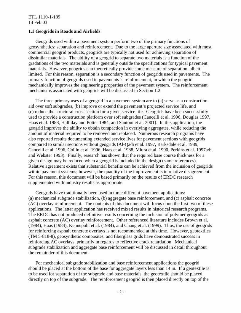
ETL 1110-1-189 14 Feb 03
USE OF GEOGRIDS IN PAVEMENT CONSTRUCTION
1.0 Introduction
Engineers are continually faced with maintaining and developing pavement infrastructure with limited financial resources. Traditional pavement design and construction practices require high-quality materials for fulfillment of construction standards. In many areas of the world, quality materials are unavailable or in short supply. Due to these constraints, engineers are often forced to seek alternative designs using substandard materials, commercial construction aids, and innovative design practices. One category of commercial construction aids is geosynthetics. Geosynthetics include a large variety of products composed of polymers and are designed to enhance geotechnical and transportation projects. Geosynthetics perform at least one of five functions: separation, reinforcement, filtration, drainage, and containment. One category of geosynthetics in particular, geogrids, has gained increasing acceptance in road construction. Extensive research programs have been conducted by the U.S. Army Engineer Research and Development Center (ERDC) and non-military agencies to develop design and construction guidance for the inclusion of geogrids in pavement systems. This document describes the use of geogrids in flexible pavement systems including design charts, product specifications, and construction guidance.
A geogrid is defined as a geosynthetic material consisting of connected parallel sets of tensile ribs with apertures of sufficient size to allow strike-through of surrounding soil, stone, or other geotechnical material (Koerner 1998). Existing commercial geogrid products include extruded geogrids, woven geogrids, welded geogrids, and geogrid composites. Extruded geogrids are formed using a polymer sheet that is punched and drawn in either one or two directions for improvement of engineering properties. Woven geogrids are manufactured by weaving polymer fibers, typically polypropylene or polyester, that can be coated for increased abrasion resistance (Berg et al. 2000). Welded geogrids are manufactured by welding the junctions of woven segments of extruded polymers. Geogrid composites are formed when geogrids are combined with other products to form a composite system capable of addressing a particular application. Extruded geogrids have shown good performance when compared to other types for pavement reinforcement applications (Cancelli et al. 1996, Miura et al. 1990, and Webster 1993). Extruded geogrids can be divided into two broad categories based upon their formation and principle application, uniaxial and biaxial. Extruded geogrids that are pre-tensioned in one direction are called uniaxial geogrids and are typically used in geotechnical engineering projects concerning reinforced earth and retaining walls. Extruded geogrids that are pre-tensioned in two directions are referred to as biaxial geogrids and are typically used in pavement applications where the direction of principle stress is uncertain. Most geogrids are made from polymers, but some products have been manufactured from natural fibers, glass, and metal strips. This document, however, will focus exclusively on polymer-based geogrids.
- 1 -
ETL 1110-1-189 14 Feb 03
1.1 Geogrids in Roads and Airfields
Geogrids used within a pavement system perform two of the primary functions of geosynthetics: separation and reinforcement. Due to the large aperture size associated with most commercial geogrid products, geogrids are typically not used for achieving separation of dissimilar materials. The ability of a geogrid to separate two materials is a function of the gradations of the two materials and is generally outside the specifications for typical pavement materials. However, geogrids can theoretically provide some measure of separation, albeit limited. For this reason, separation is a secondary function of geogrids used in pavements. The primary function of geogrids used in pavements is reinforcement, in which the geogrid mechanically improves the engineering properties of the pavement system. The reinforcement mechanisms associated with geogrids will be discussed in Section 1.2.
The three primary uses of a geogrid in a pavement system are to (a) serve as a construction aid over soft subgrades, (b) improve or extend the pavement’s projected service life, and (c) reduce the structural cross section for a given service life. Geogrids have been successfully used to provide a construction platform over soft subgrades (Cancelli et al. 1996, Douglas 1997, Haas et al. 1988, Halliday and Potter 1984, and Santoni et al. 2001). In this application, the geogrid improves the ability to obtain compaction in overlying aggregates, while reducing the amount of material required to be removed and replaced. Numerous research programs have also reported results documenting extended service lives for pavement sections with geogrids compared to similar sections without geogrids (Al-Qadi et al. 1997, Barksdale et al. 1989, Cancelli et al. 1996, Collin et al. 1996, Haas et al. 1988, Miura et al. 1990, Perkins et al. 1997a/b, and Webster 1993). Finally, research has shown that the required base course thickness for a given design may be reduced when a geogrid is included in the design (same references). Relative agreement exists that substantial benefits can be achieved from the inclusion of geogrids within pavement systems; however, the quantity of the improvement is in relative disagreement. For this reason, this document will be based primarily on the results of ERDC research supplemented with industry results as appropriate.
Geogrids have traditionally been used in three different pavement applications: (a) mechanical subgrade stabilization, (b) aggregate base reinforcement, and (c) asphalt concrete (AC) overlay reinforcement. The contents of this document will focus upon the first two of these applications. The latter application has received mixed results in historical research programs. The ERDC has not produced definitive results concerning the inclusion of polymer geogrids as asphalt concrete (AC) overlay reinforcement. Other referenced literature includes Brown et al. (1984), Haas (1984), Kennepohl et al. (1984), and Chang et al. (1999). Thus, the use of geogrids for reinforcing asphalt concrete overlays is not recommended at this time. However, geotextiles (TM 5-818-8), geosynthetic composites, and fiberglass grids have demonstrated success in reinforcing AC overlays, primarily in regards to reflective crack retardation. Mechanical subgrade stabilization and aggregate base reinforcement will be discussed in detail throughout the remainder of this document.
For mechanical subgrade stabilization and base reinforcement applications the geogrid should be placed at the bottom of the base for aggregate layers less than 14 in. If a geotextile is to be used for separation of the subgrade and base materials, the geotextile should be placed directly on top of the subgrade. The reinforcement geogrid is then placed directly on top of the
- 2 -
ETL 1110-1-189 14 Feb 03
separation geotextile for aggregate layers less than 14 in. For pavements with a design base thickness greater than or equal to 14 in., the geogrid should be placed in the middle of the base course layer (Webster 1993). However, Collin et al. (1996) and Haas et al. (1988) recommend that the geogrid be placed in the middle of the base course layer for layers in excess of 10 in., otherwise placement should occur at the layer interface. Regardless of the placement location of the geogrid, the separation geotextile is always placed at the subgrade-base interface.
1.2 Reinforcement Mechanisms
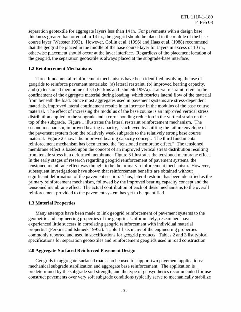
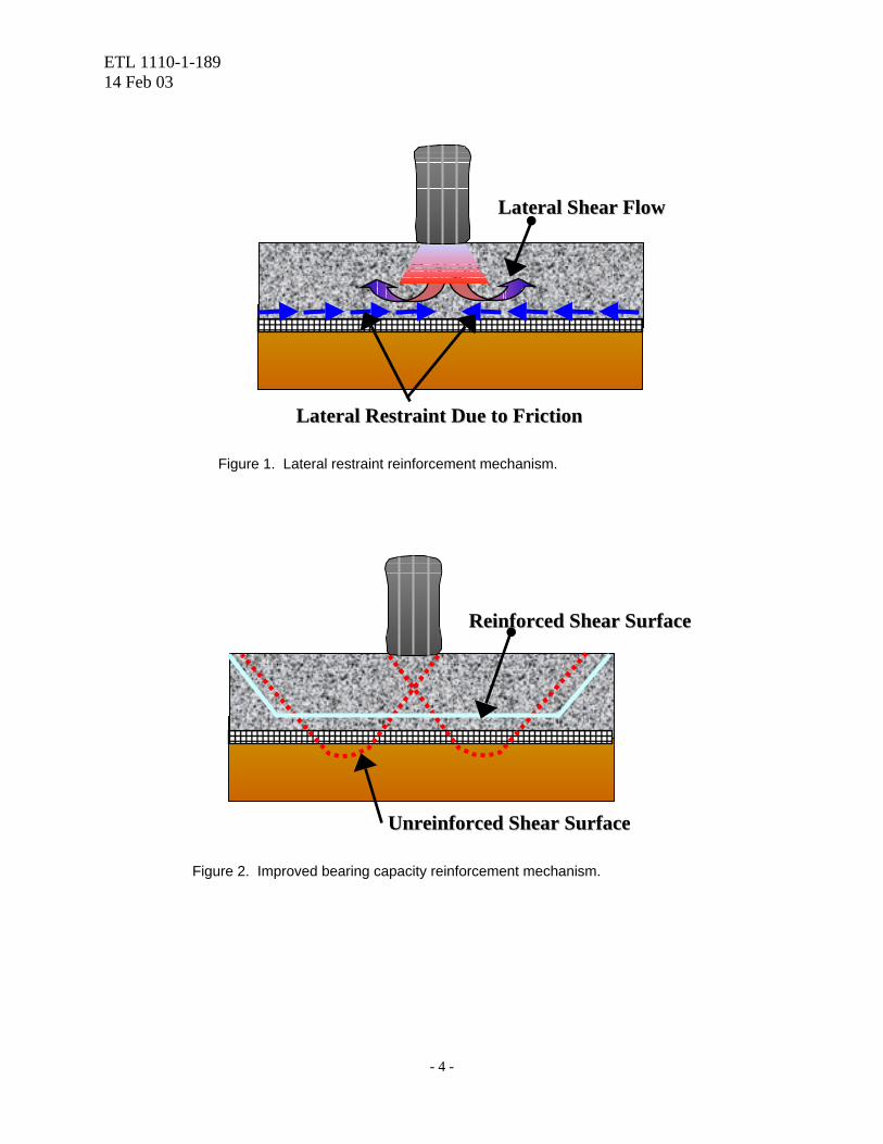
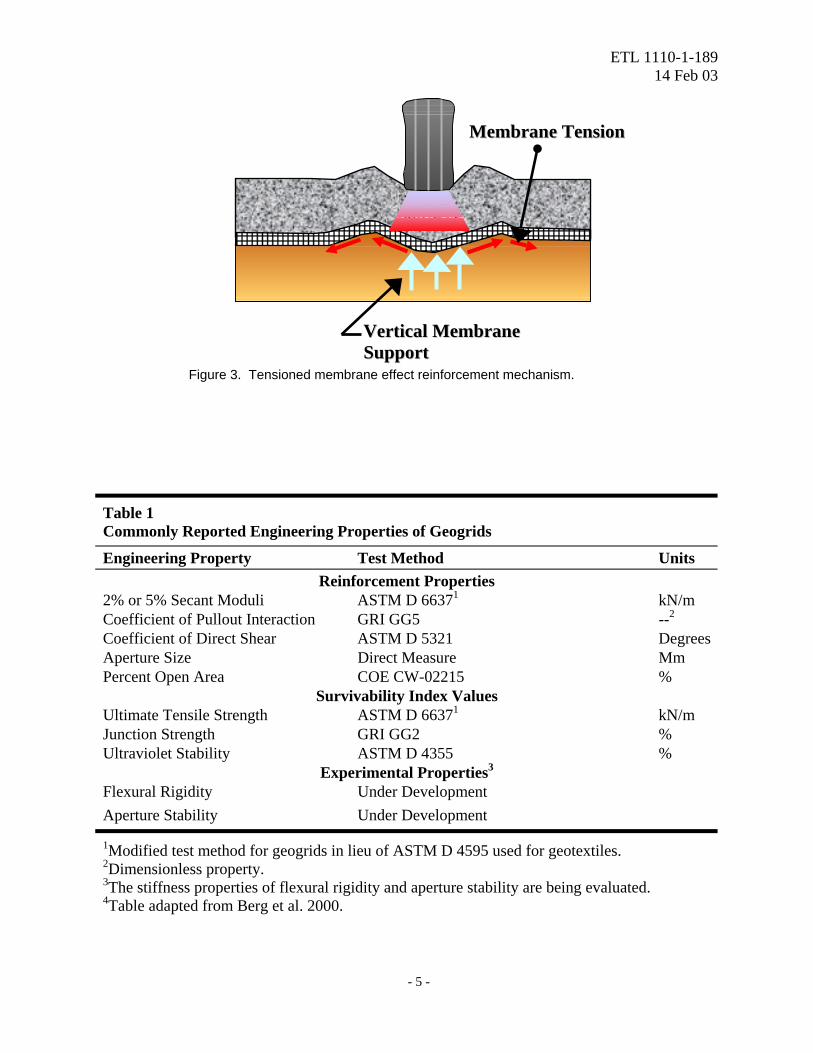
Three fundamental reinforcement mechanisms have been identified involving the use of geogrids to reinforce pavement materials: (a) lateral restraint, (b) improved bearing capacity, and (c) tensioned membrane effect (Perkins and Ishmeik 1997a). Lateral restraint refers to the confinement of the aggregate material during loading, which restricts lateral flow of the material from beneath the load. Since most aggregates used in pavement systems are stress-dependent materials, improved lateral confinement results in an increase in the modulus of the base course material. The effect of increasing the modulus of the base course is an improved vertical stress distribution applied to the subgrade and a corresponding reduction in the vertical strain on the top of the subgrade. Figure 1 illustrates the lateral restraint reinforcement mechanism. The second mechanism, improved bearing capacity, is achieved by shifting the failure envelope of the pavement system from the relatively weak subgrade to the relatively strong base course material. Figure 2 shows the improved bearing capacity concept. The third fundamental reinforcement mechanism has been termed the “tensioned membrane effect.” The tensioned membrane effect is based upon the concept of an improved vertical stress distribution resulting from tensile stress in a deformed membrane. Figure 3 illustrates the tensioned membrane effect. In the early stages of research regarding geogrid reinforcement of pavement systems, the tensioned membrane effect was thought to be the primary reinforcement mechanism. However, subsequent investigations have shown that reinforcement benefits are obtained without significant deformation of the pavement section. Thus, lateral restraint has been identified as the primary reinforcement mechanism, followed by the improved bearing capacity concept and the tensioned membrane effect. The actual contribution of each of these mechanisms to the overall reinforcement provided to the pavement system has yet to be quantified.
1.3 Material Properties
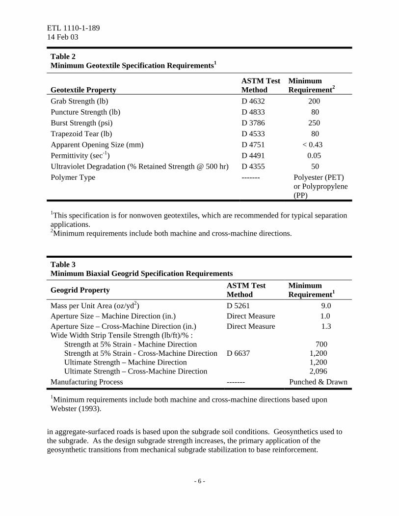
Many attempts have been made to link geogrid reinforcement of pavement systems to the geometric and engineering properties of the geogrid. Unfortunately, researchers have experienced little success in correlating geogrid reinforcement with individual material properties (Perkins and Ishmeik 1997a). Table 1 lists many of the engineering properties commonly reported and used in specifications for geogrid products. Tables 2 and 3 list typical specifications for separation geotextiles and reinforcement geogrids used in road construction.
2.0 Aggregate-Surfaced Reinforced Pavement Design
Geogrids in aggregate-surfaced roads can be used to support two pavement applications: mechanical subgrade stabilization and aggregate base reinforcement. The application is predetermined by the subgrade soil strength, and the type of geosynthetics recommended for use construct pavements over very soft subgrade conditions typically serve to mechanically stabilize
- 3 -
ETL 1110-1-189 14 Feb 03
LLaatteerraall SShheeaarr FFllooww
LLaatteerraall RReessttrraaiinntt DDuuee ttoo FFrriiccttiioonn
Figure 1. Lateral restraint reinforcement mechanism.
UUnnrreeiinnffoorrcceedd SShheeaarr SSuurrffaaccee
RReeiinnffoorrcceedd SShheeaarr SSuurrffaaccee
Figure 2. Improved bearing capacity reinforcement mechanism.
- 4 -
ETL 1110-1-189 14 Feb 03
MMeemmbbrraannee TTeennssiioonn
VVeerrttiiccaall MMeemmbbrraannee SSuuppppoorrtt
Figure 3. Tensioned membrane effect reinforcement mechanism.
Table 1 Commonly Reported Engineering Properties of Geogrids
Engineering Property Test Method Units Reinforcement Properties
2% or 5% Secant Moduli ASTM D 66371 kN/m Coefficient of Pullout Interaction GRI GG5 --2 Coefficient of Direct Shear ASTM D 5321 Degrees Aperture Size Direct Measure Mm Percent Open Area COE CW-02215 %
Survivability Index Values Ultimate Tensile Strength ASTM D 66371 kN/m Junction Strength GRI GG2 % Ultraviolet Stability ASTM D 4355 %
Experimental Properties3 Flexural Rigidity Under Development Aperture Stability Under Development
1Modified test method for geogrids in lieu of ASTM D 4595 used for geotextiles. 2Dimensionless property. 3The stiffness properties of flexural rigidity and aperture stability are being evaluated. 4Table adapted from Berg et al. 2000.
- 5 -
ETL 1110-1-189 14 Feb 03
Table 2 Minimum Geotextile Specification Requirements1
Geotextile Property ASTM Test Method
Minimum Requirement2
Grab Strength (lb) D 4632 200 Puncture Strength (lb) D 4833 80 Burst Strength (psi) D 3786 250 Trapezoid Tear (lb) D 4533 80 Apparent Opening Size (mm) D 4751 < 0.43 Permittivity (sec-1) D 4491 0.05 Ultraviolet Degradation (% Retained Strength @ 500 hr) D 4355 50 Polymer Type ------- Polyester (PET)
or Polypropylene (PP)
1This specification is for nonwoven geotextiles, which are recommended for typical separation applications. 2Minimum requirements include both machine and cross-machine directions.
Table 3 Minimum Biaxial Geogrid Specification Requirements
Geogrid Property ASTM Test Method
Minimum Requirement1
Mass per Unit Area (oz/yd2) D 5261 9.0 Aperture Size – Machine Direction (in.) Direct Measure 1.0 Aperture Size – Cross-Machine Direction (in.) Direct Measure 1.3 Wide Width Strip Tensile Strength (lb/ft)/% : Strength at 5% Strain - Machine Direction Strength at 5% Strain - Cross-Machine Direction Ultimate Strength – Machine Direction Ultimate Strength – Cross-Machine Direction
D 6637
700
1,200 1,200 2,096
Manufacturing Process ------- Punched & Drawn
1Minimum requirements include both machine and cross-machine directions based upon Webster (1993).
in aggregate-surfaced roads is based upon the subgrade soil conditions. Geosynthetics used to the subgrade. As the design subgrade strength increases, the primary application of the geosynthetic transitions from mechanical subgrade stabilization to base reinforcement.
- 6 -
ETL 1110-1-189 14 Feb 03
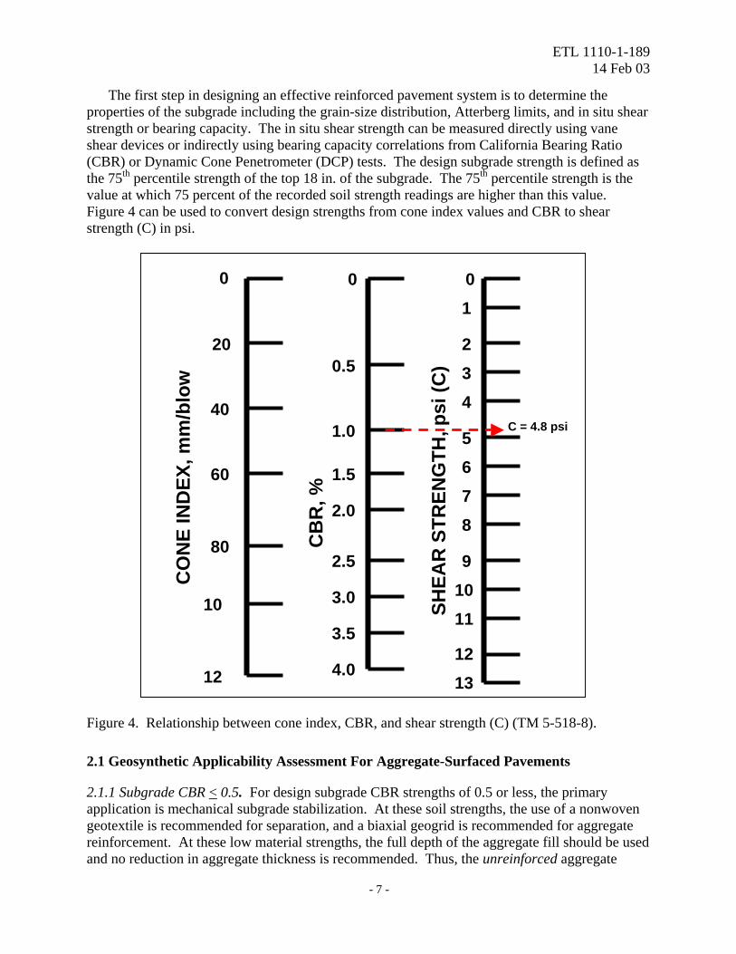
The first step in designing an effective reinforced pavement system is to determine the properties of the subgrade including the grain-size distribution, Atterberg limits, and in situ shear strength or bearing capacity. The in situ shear strength can be measured directly using vane shear devices or indirectly using bearing capacity correlations from California Bearing Ratio (CBR) or Dynamic Cone Penetrometer (DCP) tests. The design subgrade strength is defined as the 75th percentile strength of the top 18 in. of the subgrade. The 75th percentile strength is the value at which 75 percent of the recorded soil strength readings are higher than this value. Figure 4 can be used to convert design strengths from cone index values and CBR to shear strength (C) in psi.
C = 4.8 psi
CO
NE
IND
EX, m
m/b
low
SHEA
R S
TREN
GTH
, psi
(C)
CB
R, %
1312
11109
8765
432
10
4.0
3.5
3.0
2.5
2.0
1.5
1.0
0.5
0
12
10
80
60
40
20
0
Figure 4. Relationship between cone index, CBR, and shear strength (C) (TM 5-518-8).
2.1 Geosynthetic Applicability Assessment For Aggregate-Surfaced Pavements
2.1.1 Subgrade CBR < 0.5. For design subgrade CBR strengths of 0.5 or less, the primary application is mechanical subgrade stabilization. At these soil strengths, the use of a nonwoven geotextile is recommended for separation, and a biaxial geogrid is recommended for aggregate reinforcement. At these low material strengths, the full depth of the aggregate fill should be used and no reduction in aggregate thickness is recommended. Thus, the unreinforced aggregate
- 7 -

ETL 1110-1-189 14 Feb 03
thickness design should be used for subgrade strengths of 0.5 CBR or less. The nonwoven geotextile is placed directly on the subgrade followed by the geogrid and then the aggregate fill. The designed construction platform serves as a bridge over very soft material, a compaction aid for obtaining target densities, and a construction expedient. 2.1.2 Subgrade 0.5 < CBR < 2.0. For design subgrade CBR strengths of 2.0 or less, both the mechanical subgrade stabilization and base reinforcement applications are mobilized. A nonwoven geotextile is recommended for separation at subgrade strengths of 2.0 CBR or less. The use of a biaxial geogrid for reinforcement is also generally cost-effective at subgrade CBR values of 2.0 or less, in terms of aggregate savings. Thus, for this subgrade strength level both a geotextile and geogrid are generally recommended, and the aggregate thickness can be reduced using the appropriate reinforced bearing capacity factor presented in the following design procedure section. 2.1.3 Subgrade 2.0 < CBR < 4.0. The use of a nonwoven geotextile for separation is generally recommended for fine-grained subgrades with design subgrade CBR values less than or equal to 4. A nonwoven geotextile should also be used for separation when the designer has experienced separation problems with the construction materials during previous construction projects. For design subgrade CBR strengths between 2.0 and 4.0, the primary geogrid application is base reinforcement. However, the cost effectiveness of using a geogrid at these subgrade strengths should be determined by performing a life-cycle cost analysis. Research has indicated substantial extensions in pavement service life and significant potential for base thickness reductions for AC-surfaced pavements at these subgrade strengths. However, insufficient data is available for aggregate-surfaced reinforced roads at these subgrade strengths to accurately define an appropriate bearing capacity factor. Thus, it is recommended that the designer use the bearing capacity factor for the inclusion of both a geotextile and a geogrid provided in the following design procedure section. This recommendation is based on the assumption that the geotextile serves to separate the different pavement materials and provides little reinforcement benefit. 2.1.4 Subgrade CBR > 4.0. Research has indicated significant reinforcement potential at these subgrade strength values, however ERDC has yet to quantify the benefits conclusively. The primary geogrid application at these subgrade strength values is base reinforcement. Until additional research is accomplished, a life-cycle cost analysis should be conducted to determine the economical feasibility of geogrid reinforcement for projects in which the design subgrade CBR strength is greater than 4.0 using the design procedures described in this document. Future research programs may develop conclusive results for designing geogrid-reinforced aggregate-surfaced pavements at these subgrade strength values. Geogrids can be used as a construction expedient to solve site-specific construction problems, such as site mobility and localized soft soil deposits. 2.2 Reinforced Aggregate-Surfaced Pavement Design Procedure 2.2.1 Determine the Subgrade Shear Strength (C). The first step in designing a reinforced aggregate-surfaced pavement is to determine the design subgrade conditions. The design subgrade conditions can be determined using field CBR tests, vane shear tests, DCP tests, or from laboratory soaked CBR tests as noted under Section 2.0. Once the design subgrade
- 8 -
ETL 1110-1-189 14 Feb 03
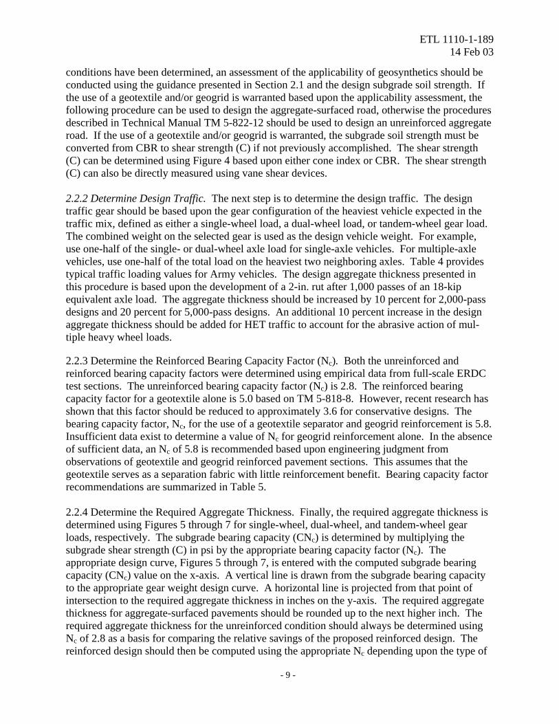
conditions have been determined, an assessment of the applicability of geosynthetics should be conducted using the guidance presented in Section 2.1 and the design subgrade soil strength. If the use of a geotextile and/or geogrid is warranted based upon the applicability assessment, the following procedure can be used to design the aggregate-surfaced road, otherwise the procedures described in Technical Manual TM 5-822-12 should be used to design an unreinforced aggregate road. If the use of a geotextile and/or geogrid is warranted, the subgrade soil strength must be converted from CBR to shear strength (C) if not previously accomplished. The shear strength (C) can be determined using Figure 4 based upon either cone index or CBR. The shear strength (C) can also be directly measured using vane shear devices. 2.2.2 Determine Design Traffic. The next step is to determine the design traffic. The design traffic gear should be based upon the gear configuration of the heaviest vehicle expected in the traffic mix, defined as either a single-wheel load, a dual-wheel load, or tandem-wheel gear load. The combined weight on the selected gear is used as the design vehicle weight. For example, use one-half of the single- or dual-wheel axle load for single-axle vehicles. For multiple-axle vehicles, use one-half of the total load on the heaviest two neighboring axles. Table 4 provides typical traffic loading values for Army vehicles. The design aggregate thickness presented in this procedure is based upon the development of a 2-in. rut after 1,000 passes of an 18-kip equivalent axle load. The aggregate thickness should be increased by 10 percent for 2,000-pass designs and 20 percent for 5,000-pass designs. An additional 10 percent increase in the design aggregate thickness should be added for HET traffic to account for the abrasive action of mul-tiple heavy wheel loads.
2.2.3 Determine the Reinforced Bearing Capacity Factor (Nc). Both the unreinforced and reinforced bearing capacity factors were determined using empirical data from full-scale ERDC test sections. The unreinforced bearing capacity factor (Nc) is 2.8. The reinforced bearing capacity factor for a geotextile alone is 5.0 based on TM 5-818-8. However, recent research has shown that this factor should be reduced to approximately 3.6 for conservative designs. The bearing capacity factor, Nc, for the use of a geotextile separator and geogrid reinforcement is 5.8. Insufficient data exist to determine a value of Nc for geogrid reinforcement alone. In the absence of sufficient data, an Nc of 5.8 is recommended based upon engineering judgment from observations of geotextile and geogrid reinforced pavement sections. This assumes that the geotextile serves as a separation fabric with little reinforcement benefit. Bearing capacity factor recommendations are summarized in Table 5. 2.2.4 Determine the Required Aggregate Thickness. Finally, the required aggregate thickness is determined using Figures 5 through 7 for single-wheel, dual-wheel, and tandem-wheel gear loads, respectively. The subgrade bearing capacity (CNc) is determined by multiplying the subgrade shear strength (C) in psi by the appropriate bearing capacity factor (Nc). The appropriate design curve, Figures 5 through 7, is entered with the computed subgrade bearing capacity (CNc) value on the x-axis. A vertical line is drawn from the subgrade bearing capacity to the appropriate gear weight design curve. A horizontal line is projected from that point of intersection to the required aggregate thickness in inches on the y-axis. The required aggregate thickness for aggregate-surfaced pavements should be rounded up to the next higher inch. The required aggregate thickness for the unreinforced condition should always be determined using Nc of 2.8 as a basis for comparing the relative savings of the proposed reinforced design. The reinforced design should then be computed using the appropriate Nc depending upon the type of
- 9 -
ETL 1110-1-189 14 Feb 03
Table 4 Typical Traffic Loading Data for Military Vehicles
Design Wheel Load1, lb
Vehicle Type
Gross Vehicle Weight, lb
Single-Wheel
Dual-Wheel
Tandem-Wheel
M54A2C, 6 x 6, 5-Ton Cargo Truck 40,200 5,000 -- 16,000
M929A1, 6 x 6, 5-Ton Dump Truck 35,065 6,000 -- 12,000
M1062, 4 x 4, Semitrailer Fuel Truck 64,600 -- -- 34,000
M172A1, 4 x 4, 25-Ton Semitrailer 66,600 -- -- 42,000
M872A1-3, 6 x 6, 34-Ton Semitrailer 86,440 -- -- 57,000
M870, 6 x 6, 40-Ton Semitrailer 96,000 -- -- 57,000 M747, 8 x 8, 60-Ton HET Semitrailer 152,000 -- -- 27,000
M1000, 8 x 8, 70-Ton HET Semitrailer 190,400 -- -- 37,000
621E, 14-18 cu. yd. Caterpillar Scraper 115,195 32,000 -- --
RTCH, 50,000 lb 166,800 69,000 -- --
1Design wheel loads for geosynthetic-reinforced roads. Use 1/2 the maximum single-wheel or dual-wheel axle load. For multiple axles, use 1/2 the total load on the heaviest 2 adjacent axles and treat as a tandem-wheel gear load.
- 10 -
ETL 1110-1-189 14 Feb 03
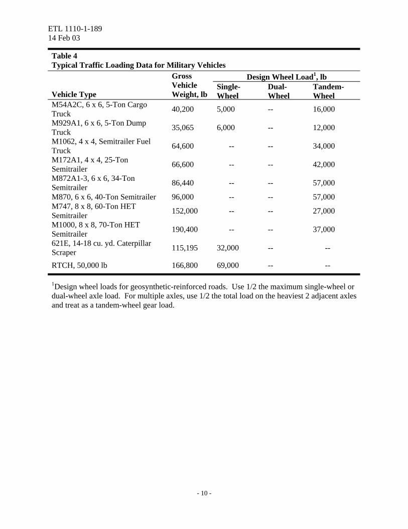
reinforcement recommended as shown in Table 5. A minimum aggregate thickness of 6 inches is recommended for aggregate-surfaced pavements. Aggregate-surfaced design examples are provided in Appendix A. Note that standard frost design procedures should be used for regions in which significant frost penetration occurs.
Table 5 Reinforced Bearing Capacity Factors, Nc
1, for Aggregate-Surfaced Pavements
Step 1: Determine Design Subgrade Soil Strength and Geosynthetic Applicability
CBR < 0.5 0.5 < CBR < 2.0 2.0 < CBR < 4.0 CBR > 4.0
Both a geogrid and a geotextile are recommended. Use this design procedure for aggregate thickness reduction.
A geotextile is required for fine-grained subgrades. A geogrid may also be cost-effective. Perform a life cycle cost analysis.
Geotextile
Geogrid Both2
Geotextile Geogrid
Both
Use a geotextile and a geogrid at subgrade-base interface. No aggregate thickness reduction recommended. Use TM 5-822-12 for thickness design
5.03 5.8 5.8 5.03 5.8 5.8
Perform a cost analysis. Consider “hidden” benefits. Inadequate data is available to determine bearing
1The unreinforced bearing capacity factor, Nc, is 2.8. 2Both a geotextile and a geogrid are recommended. The geotextile serves primarily as a separation fabric. 3Use a factor of 3.6 for conservative geotextile-reinforced pavement designs.
- 11 -

ETL 1110-1-189 14 Feb 03
Single Wheel LoadOne Layer System
Tire Pressure = 80 psi
0
5
10
15
20
25
30
35
40
45
50
55
60
65
70
1 10 100
Subgrade Bearing Capacity, CNc, psi
Req
uire
d A
ggre
gate
Dep
th, i
n
0
5
10
15
20
25
30
35
40
45
50
55
60
65
70
Single Wheel 20,000 lbs15,000 lbs10,000 lbs 5,000 lbs
Adapted From Steward et al. 1977
Figure 5. Aggregate-surfaced pavement design curves for single-wheel loads.
- 12 -

ETL 1110-1-189 14 Feb 03
- 13 -
Dual Wheel LoadOne La y e r S y st e m
Ti r e P r e ssur e = 8 0 psi
0
5
10
15
20
25
30
35
40
45
50
55
60
65
70
1 10 100
S ubgr a de Be a r i ng Ca pa c i t y , CN c , psi
0
5
10
15
20
25
30
35
40
45
50
55
60
65
70
Dua l Whe e l Loa d20, 000 l bs1 6, 000 l bs1 2, 000 l bs 9, 000 l bs 4, 000 l bs
Adapt ed Fr om St ewar d et al . 1 977
3aa = Radi us of Cont act Ar ea
Figure 6. Aggregate-surfaced pavement design curves for dual-wheel loads.

ETL 1110-1-189 14 Feb 03
Tandem Wheel Gear WeightOne Layer System
Tire Pressure = 80 psi
0
5
10
15
20
25
30
35
40
45
50
55
60
65
70
1 10 100
Subgrade Bearing Capacity, CNc, psi
Req
uire
d A
ggre
gate
Dep
th, i
n.
0
5
10
15
20
25
30
35
40
45
50
55
60
65
70
Tandem Wheel Gear
43,750 lbs37,500 lbs24,000 lbs17,500 lbs 8,000 lbs
Adapted From Steward et al. 1977
a = Radius of Contact Area3a
54"
Figure 7. Aggregate-surfaced pavement design curves for tandem-wheel gear loads.
- 14 -

ETL 1110-1-189 14 Feb 03
3.0 Reinforced Flexible Pavement Design
Geogrids can be used to accomplish both mechanical subgrade stabilization and aggregate base reinforcement in flexible pavements. Like the aggregate-surfaced pavement design, the application is typically predetermined by the subgrade soil strength. Different combinations of geosynthetics are recommended for use in flexible pavements based upon the subgrade soil conditions. Geosynthetics used to construct roads and airfields over very soft subgrade conditions typically serve to mechanically stabilize the subgrade. As the design subgrade strength increases, the primary application of the geosynthetics transitions from mechanical subgrade stabilization to base reinforcement. The reinforced road design procedures presented herein can be used for airfields provided the appropriate design procedures for airfields are used to generate the unreinforced design.
3.1 Geosynthetic Applicability Assessment For Flexible Pavement Design
3.1.1 Subgrade CBR < 0.5. For design subgrade CBR strengths of 0.5 or less, the primary application is mechanical subgrade stabilization. At these soil strengths, it is recommended that a construction platform be designed to facilitate the construction of the flexible pavement. The construction platform should be designed using the procedures described in Section 2.0. The construction platform will serve as the subbase for the flexible pavement system.
3.1.2 Subgrade 0.5 < CBR < 4.0. For design subgrade CBR strengths of 4.0 or less, both the mechanical subgrade stabilization and base reinforcement applications are mobilized. A nonwoven geotextile is recommended for separation for fine-grained subgrades at strengths of 4.0 CBR or less, and the use of a geogrid for reinforcement should be considered. Thus, for this subgrade strength level both a geotextile and geogrid may be warranted, and the aggregate thickness can be reduced using Webster’s empirical reinforced pavement thickness equivalency chart (Figure 8) presented in the following design procedure section.
3.1.3 Subgrade 4.0 < CBR < 8.0. For subgrade CBR strengths greater than 4.0, a geotextile separator is not recommended unless the designer has experienced separation problems with the construction materials during previous construction projects. For design subgrade CBR strengths between 4.0 and 8.0, the primary geogrid application is base reinforcement. Research has indicated substantial extensions in pavement service life and significant potential for base thickness reductions. Thus, the designer should use Webster’s reinforced pavement thickness equivalency chart (Figure 8) to determine the required reinforced pavement thickness. A life cycle cost analysis should then be made to determine the cost effectiveness of including geogrid reinforcement.
3.1.4 Subgrade CBR > 8.0. A geotextile separator is not recommended unless prior separation problems have been noted for the specific construction materials. The primary application of geogrid reinforcement at high subgrade soil strengths is base reinforcement. These subgrade soil strengths are outside the database used to develop Webster’s reinforced pavement thickness equivalency chart, and it should not be used for high subgrade soil strengths. An alternative procedure is to base the reinforced design on test section results. This can be accomplished by defining a Base Course Reduction (BCR) factor as the reinforced base thickness divided by the
- 15 -
ETL 1110-1-189 14 Feb 03
unreinforced base thickness for a given traffic level. The required depth of reinforced aggregate base is then computed using Equation 1:
t(reinforced base) = t(unreinforced base) x BCR (Equation 1)
This BCR factor should be determined using the materials and construction conditions that will be used during the actual pavement construction.
3.2 Reinforced Flexible Road Design Procedure
3.2.1 Determine the Pavement Layer Properties. The first step in designing a reinforced flexible pavement is to determine the design subgrade conditions as noted under Section 2.0. Once the design subgrade conditions have been determined, an assessment of the applicability of geosynthetics should be conducted using the guidance presented in Section 3.1 and Table 6. If the use of a geotextile and/or geogrid is warranted based upon the applicability assessment, the following procedure can be used to design the reinforced flexible pavement, otherwise the procedures described in Technical Manual TM 5-822-5 should be used to design an unreinforced flexible pavement. The subgrade soil CBR can be determined using Figure 4 based upon either cone index or shear strength (C). The shear strength (C) can be directly measured using vane shear devices.
Each aggregate layer, base and subbase (if used), in the flexible pavement system must meet strength and gradation requirements defined in TM 5-822-5. The material requirements for the bituminous surface course layer are defined in TM 5-822-8.
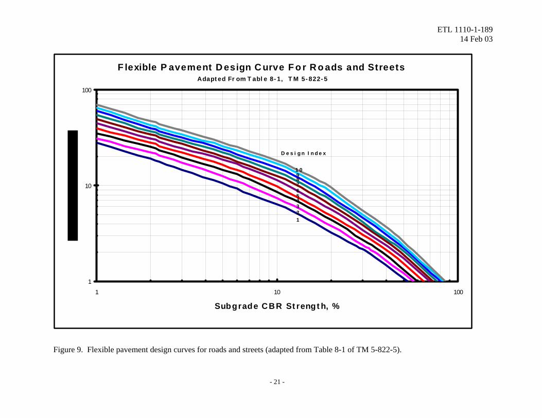
3.2.2 Determine Design Traffic. The next step is to determine the design traffic. The design traffic should be determined according to TM 5-822-5, which results in a design index (DI). The design index combines the effect of average vehicle axle loadings and expected traffic volume as expressed by road classification. The design index ranges from 1 to 10 in order of increasing traffic loading and volumes. The design index is selected using Table 3-1 of TM 5-822-5, presented here as Table 7 for clarity.
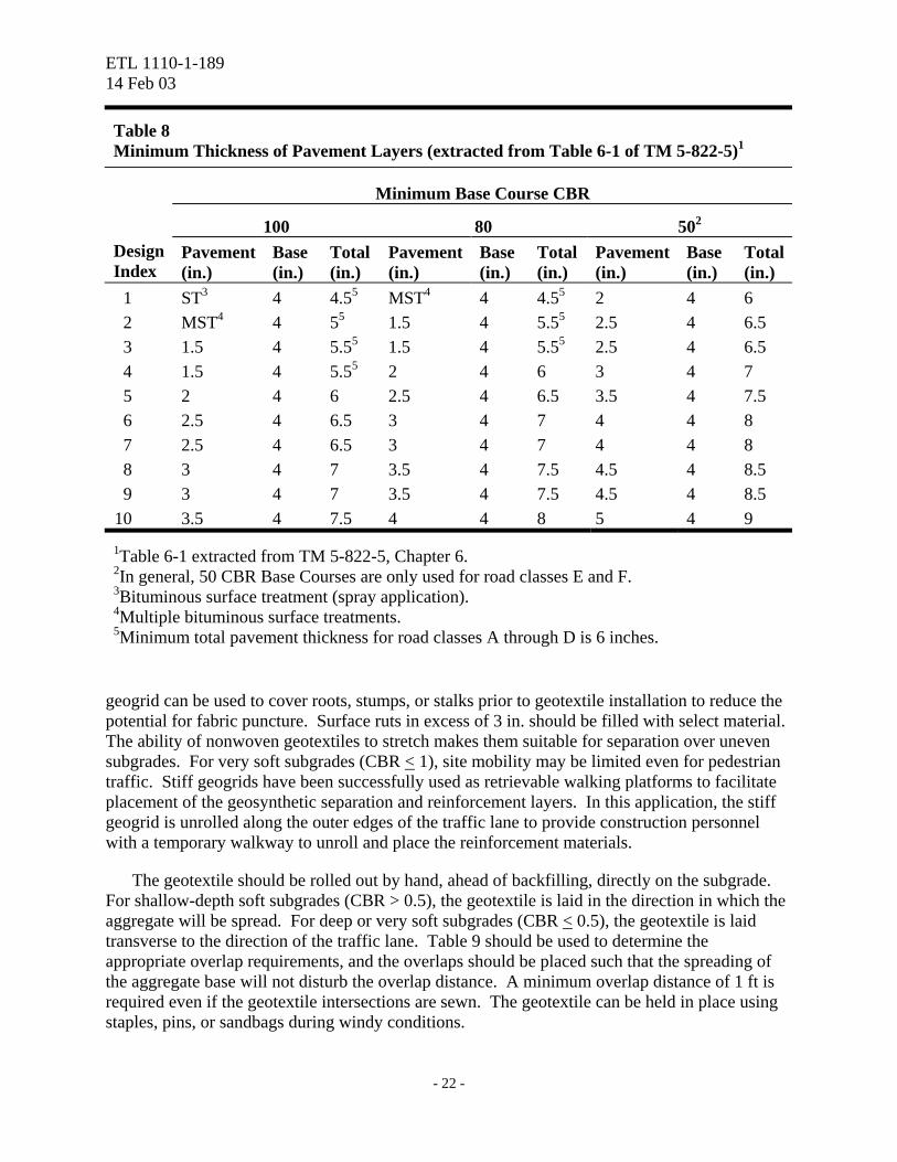
3.2.3 Determine the Required Layer Thicknesses. The next step is to design an unreinforced flexible pavement for the given subgrade conditions. The design subgrade CBR strength is determined according to the methods presented previously. Figure 8-1 of TM 5-822-5 (Figure 9 in this document) is entered with the appropriate CBR of the supporting layer, either the subgrade strength or the subbase strength. The required pavement thickness above the supporting layer is determined by drawing a vertical line from the strength on the x-axis to the intersection of the design index. A horizontal line is then projected from the intersection to the required pavement thickness on the y-axis. The required pavement thickness should be rounded up to the nearest 0.5 inches for surfaced flexible pavements. Figure 9 was adapted from Figure 8-1 of TM 5-822-5 for clarity. Minimum thickness values for the surface AC and base courses are provided in Table 6-1 of Technical Manual 5-822-5, and are presented in Table 8 of this document. Generally, an asphalt thickness of 3 in. or less is appropriate for design index values of 7 or less. The minimum required base thickness is 4 in. The final pavement structure is determined by using the minimum AC thickness for the available aggregate as noted in Table 8. The difference between the total required pavement thickness above the subgrade/subbase
- 16 -

ETL 1110-1-189 14 Feb 03
Webster's Reinforced Pavement Thickness Design
6
8
10
12
14
16
18
20
4 6 8 10 12 14 16 18 20
Equivalent Reinforced Pavement Thickness, in.(AC + Base)
Unr
einf
orce
d Pa
vem
ent T
hick
ness
, in.
(AC
+ B
ase)
Figure 8. Webster’s reinforced pavement thickness equivalency chart.
- 17 -
ETL 1110-1-189 14 Feb 03
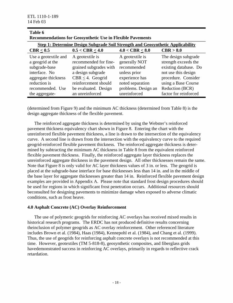
Table 6 Recommendations for Geosynthetic Use in Flexible Pavements
Step 1: Determine Design Subgrade Soil Strength and Geosynthetic Applicability CBR < 0.5 0.5 < CBR < 4.0 4.0 < CBR < 8.0 CBR > 8.0 Use a geotextile and a geogrid at the subgrade-base interface. No aggregate thickness reduction is recommended. Use the aggregate-
A geotextile is recommended for fine-grained subgrades with a design subgrade CBR < 4. Geogrid reinforcement should be evaluated. Design an unreinforced
A geotextile is generally NOT recommended unless prior experience has noted separation problems. Design an unreinforced
The design subgrade strength exceeds the existing database. Do not use this design procedure. Consider using a Base Course Reduction (BCR) factor for reinforced
(determined from Figure 9) and the minimum AC thickness (determined from Table 8) is the design aggregate thickness of the flexible pavement.
The reinforced aggregate thickness is determined by using the Webster’s reinforced pavement thickness equivalency chart shown in Figure 8. Entering the chart with the unreinforced flexible pavement thickness, a line is drawn to the intersection of the equivalency curve. A second line is drawn from the intersection with the equivalency curve to the required geogrid-reinforced flexible pavement thickness. The reinforced aggregate thickness is deter-mined by subtracting the minimum AC thickness in Table 8 from the equivalent reinforced flexible pavement thickness. Finally, the reinforced aggregate layer thickness replaces the unreinforced aggregate thickness in the pavement design. All other thicknesses remain the same. Note that Figure 8 is only valid for AC layer thickness values of 3 in. or less. The geogrid is placed at the subgrade-base interface for base thicknesses less than 14 in. and in the middle of the base layer for aggregate thicknesses greater than 14 in. Reinforced flexible pavement design examples are provided in Appendix A. Please note that standard frost design procedures should be used for regions in which significant frost penetration occurs. Additional resources should beconsulted for designing pavements to minimize damage when exposed to adverse climatic conditions, such as frost heave.
4.0 Asphalt Concrete (AC) Overlay Reinforcement
The use of polymeric geogrids for reinforcing AC overlays has received mixed results in historical research programs. The ERDC has not produced definitive results concerning theinclusion of polymer geogrids as AC overlay reinforcement. Other referenced literature includes Brown et al. (1984), Haas (1984), Kennepohl et al. (1984), and Chang et al. (1999). Thus, the use of geogrids for reinforcing asphalt concrete overlays is not recommended at this time. However, geotextiles (TM 5-818-8), geosynthetic composites, and fiberglass grids havedemonstrated success in reinforcing AC overlays, primarily in regards to reflective crack retardation.
- 18 -

ETL 1110-1-189 14 Feb 03
Table 7 Pavement Design Index (extracted from Table 3-1 of TM 5-822-5)1
Pavement Design Index by Road/Street Class3
Traffic Category2 A B C D E F I 2 2 2 1 1 1 II 3 2 2 2 2 1 III 4 4 4 3 3 2 IV 5 5 5 4 4 3 IVA 6 6 6 5 5 4 V (60-kilopound (kip) tracked vehicles or 15-kip forklifts 500/day 200/day 100/day 40/day 10/day 4/day 1/day
7 6 6 6 6 5 5 5
7 6 6 6 6 5 5 5
7 6 6 6 6 5 5 5
7 6 6 6 5 5 5 4
7 6 6 6 5 5 4 4
--4
--4 --4 6 5 5 4 4
VI (90-kip tracked vehicles or 25-kip forklifts 200/day 100/day 40/day 10/day 4/day 1/day 1/week
9 8 7 6 6 5 5
9 8 7 6 6 5 5
9 8 7 6 6 5 5
9 8 7 6 6 5 4
9 8 7 6 6 5 4
--4 8 7 6 6 5 4
VII (120-kip tracked vehicles 100/day 40/day 10/day 4/day 1/day 1/week
10 9 8 7 6 5
10 9 8 7 6 5
10 9 8 7 6 5
10 9 8 7 6 5
10 9 8 7 6 5
10 9 8 7 6 5
1Table 3-1 extracted from TM 5-822-5 for clarity. 2Traffic Category defined in TM 5-822-5, Chapter 3. 3Road/street class defined in TM 5-822-2, Chapter 5. 4Traffic limited to 100 vehicles per day.
- 19 -
ETL 1110-1-189 14 Feb 03
5.0 Life Cycle Cost Analysis
A detailed cost analysis should be performed to determine if the geogrid-reinforced pavement design is justified. The cost of the geosynthetic-reinforced pavement section should be compared to the cost of an unreinforced pavement section. A direct cost comparison based upon material savings alone, however, does not include the indirect benefits of using geogrid reinforcement. These indirect benefits include increased site mobility, improved ease of construction, reduced haul costs for additional aggregate, and an improved ability to meet compaction requirements over soft subgrades. These indirect benefits may compensate for slight increases in material costs. An appropriate cost analysis procedure should consist of the following steps as adapted from Berg et al. (2000):
1. Compute the initial material and construction costs for the pavement. a. Compute costs for the unreinforced design. b. Compute costs for each reinforced design option. c. Compute costs for other alternatives.
2. Compute the life-cycle costs for the pavement. a. Compute the life-cycle costs for the unreinforced pavement. b. Compute the life-cycle costs for the reinforced design options. c. Compute the life-cycle costs for other alternatives.
3. List the benefits that are difficult to quantify in terms of dollar amounts or the “hidden” benefits.
4. Compare the initial construction costs, the life-cycle costs, and the “hidden” benefits for each design alternative. Select the alternative that meets the objectives of the project at the minimum cost. The value of “hidden” benefits must be considered and can be used to distinguish between alternatives with similar financial requirements.
6.0 Construction of Geosynthetic-Reinforced Pavements
The construction of geosynthetic-reinforced pavements may require modifications to standard road construction procedures, primarily to prevent damage to the geosynthetics. Pavement construction over very soft subgrades requires special consideration to both protect the geosynthetics and prevent overloading by construction traffic. The following sections describe recommended procedures for accomplishing pavement construction with geosynthetic reinforcement.
6.1 Geotextile Installation
Prior to installation of the geotextile, the site should be cleared, grubbed, and excavated to the design grade unless the subgrade CBR is less than 2.0. If the subgrade soil CBR is 2.0 or greater, the subgrade should be compacted to identify any unsuitable materials that may damage the geotextile. Unsuitable items such as stumps, roots, etc. should be removed if practical. If the subgrade soil CBR is less than 2.0, surface materials such as vegetation and root mats may be advantageous and should not be removed. Small sections of
- 20 -
ETL 1110-1-189 14 Feb 03
- 21 -
F lexible P avement D esign C urve F o r R o ads and StreetsAdapt ed Fr om T abl e 8- 1, T M 5- 822- 5
1
10
100
1 10 100
Subgrade CBR St rengt h, %
D e s i g n I n d e x
1 0987654321
Figure 9. Flexible pavement design curves for roads and streets (adapted from Table 8-1 of TM 5-822-5).
ETL 1110-1-189 14 Feb 03
Table 8 Minimum Thickness of Pavement Layers (extracted from Table 6-1 of TM 5-822-5)1
Minimum Base Course CBR
100 80 502 Design Index
Pavement (in.)
Base (in.)
Total(in.)
Pavement (in.)
Base (in.)
Total (in.)
Pavement (in.)
Base (in.)
Total (in.)
1 ST3 4 4.55 MST4 4 4.55 2 4 6 2 MST4 4 55 1.5 4 5.55 2.5 4 6.5 3 1.5 4 5.55 1.5 4 5.55 2.5 4 6.5 4 1.5 4 5.55 2 4 6 3 4 7 5 2 4 6 2.5 4 6.5 3.5 4 7.5 6 2.5 4 6.5 3 4 7 4 4 8 7 2.5 4 6.5 3 4 7 4 4 8 8 3 4 7 3.5 4 7.5 4.5 4 8.5 9 3 4 7 3.5 4 7.5 4.5 4 8.5
10 3.5 4 7.5 4 4 8 5 4 9
1Table 6-1 extracted from TM 5-822-5, Chapter 6. 2In general, 50 CBR Base Courses are only used for road classes E and F. 3Bituminous surface treatment (spray application). 4Multiple bituminous surface treatments. 5Minimum total pavement thickness for road classes A through D is 6 inches.
geogrid can be used to cover roots, stumps, or stalks prior to geotextile installation to reduce the potential for fabric puncture. Surface ruts in excess of 3 in. should be filled with select material. The ability of nonwoven geotextiles to stretch makes them suitable for separation over uneven subgrades. For very soft subgrades (CBR < 1), site mobility may be limited even for pedestrian traffic. Stiff geogrids have been successfully used as retrievable walking platforms to facilitate placement of the geosynthetic separation and reinforcement layers. In this application, the stiff geogrid is unrolled along the outer edges of the traffic lane to provide construction personnel with a temporary walkway to unroll and place the reinforcement materials.
The geotextile should be rolled out by hand, ahead of backfilling, directly on the subgrade. For shallow-depth soft subgrades (CBR > 0.5), the geotextile is laid in the direction in which the aggregate will be spread. For deep or very soft subgrades (CBR < 0.5), the geotextile is laid transverse to the direction of the traffic lane. Table 9 should be used to determine the appropriate overlap requirements, and the overlaps should be placed such that the spreading of the aggregate base will not disturb the overlap distance. A minimum overlap distance of 1 ft is required even if the geotextile intersections are sewn. The geotextile can be held in place using staples, pins, or sandbags during windy conditions.
- 22 -

ETL 1110-1-189 14 Feb 03
Table 9 Geosynthetic Overlap Requirements For Use Pavements
Step 1: Determine Design Subgrade Soil Strength and Geosynthetic Applicability CBR < 1.0 1.0 < CBR < 4.0 CBR > 4.0
3 ft 2 ft 1 ft
6.2 Geogrid Installation
Prior to installation of the geogrid, the site should be cleared, grubbed, and excavated to the design grade if not done previously for geotextile placement. As noted in Section 6.1, small sections of geogrid can be used to cover roots, stumps, or stalks prior to geotextile installation to reduce the potential for fabric puncture. Also noted in Section 6.1, stiff geogrids have been successfully used as retrievable walking platforms to facilitate placement of the geosynthetic separation and reinforcement layers. In this application, the stiff geogrid is unrolled along the outer edges of the traffic lane to provide construction personnel with a temporary walkway to unroll and place the reinforcement materials.
The geogrid should be rolled out by hand, ahead of backfilling, directly on the subgrade or geotextile (if required) for design aggregate thicknesses less than 14 inches. For design aggregate thicknesses in excess of 14 in., the geogrid should be placed in the middle of the aggregate layer. For shallow-depth soft subgrades (CBR > 0.5), the geogrid is laid in the direction in which the aggregate will be spread. For deep or very soft subgrades (CBR < 0.5), the geogrid is laid transverse to the direction of the traffic lane. Table 9 should be used to determine the appropriate overlap requirements, and the overlaps should be placed such that the spreading of the aggregate base will not disturb the overlap distance. The geogrid can be held in place using staples, pins, or sand bags for windy conditions.
6.3 Aggregate Placement
Vehicles must not be driven on the unprotected geosynthetics prior to aggregate placement. For very soft subgrades (CBR < 1.0), an effective construction procedure is to install the aggregate thicker and narrower than the design. Thus, the aggregate should be placed in the center of the traffic lane at a depth greater than the final design grade. The weight of this material will begin to displace excess water from the subgrade and begin subgrade consolidation. This results in an increase in the overall subgrade strength beneath the traffic lane. After the required amount of aggregate for the roadway and shoulders has been placed in the center of the traffic lane, the excess aggregate can be spread laterally to the shoulders of the roadway until the design grade is achieved. The aggregate material can then be compacted to the design thickness. Care should be taken to spread the aggregate in the direction of the geosynthetic overlaps.
For subgrade CBR strengths between 1.0 and 3.0, the full design aggregate thickness should be placed in one lift. Thinner lifts of aggregate run the risk of damaging the geosynthetics or
- 23 -
ETL 1110-1-189 14 Feb 03
failure of the roadway due to overloading by construction equipment. The aggregate should always be spread from the center of the roadway to the outer edges. For subgrade CBR strengths greater than 3.0, standard road construction procedures can be applied.
The geotextile and geogrid properties specified in Tables 2 and 3, respectively, are designed to survive installation in typical pavement construction applications. Construction sites demonstrating extremely harsh construction conditions may require reconsideration of the generic geotextile specifications. Examples of harsh environments include geosynthetic placement over large quantities of roots or tree stumps, the use of over-sized aggregate (D50 > 3 in.), dump heights in excess of 12 ft, and operations on thin aggregate lifts.
8.0 Bibliography and References
a. Al-Qadi, I. L., Brandon, T. L., Valentine, R. J., Lacina, B. A., and Smith, T. E. (1994). “Laboratory Evaluation of Geosynthetic Reinforced Pavement Sections,” Transportation Research Record 1439, pp. 25-31.
b. Al-Qadi, I. L., Brandon, T. L., and Bhutta, A. (1997). “Geosynthetic Stabilized Flexible Pavements,” Proceedings of Geosynthetics ’97, IFAI, Vol. 2, Long Beach, California, pp. 647-662.
c. Anderson, P., and Killeavy, M. (1989). “Geotextiles and Geogrids: Cost Effective Alternate Materials for Pavement Design and Construction,” Proceedings of Geosynthetics ’89, IFAI, Vol. 2, San Diego, California, pp. 353-360.
d. Barenberg, E. J., Hales, J., and Dowland, J. (1975). “Evaluation of Soil-Aggregate Systems with MIRAFI Fabric,” University of Illinois Report No. UILU-ENG-75-2020, prepared for Celanese Fibers Marketing Company.
e. Barker, W. R. (1987). “Open-Graded Bases for Airfield Pavements,” Technical Report GL-87-16, U.S. Army Engineer Waterways Experiment Station, Vicksburg, MS.
f. Barksdale, R. D., Brown, S. F., and Chan, F. (1989). “Potential Benefits of Geosynthetics in Flexible Pavement Systems,” National Cooperative Highway Research Program Report No. 315, Transportation Research Board, National Research Council, Washington, D.C.
g. Bender, D. A., and Barenberg, E. J. (1978). “Design and Behavior of Soil-Fabric-Aggregate Systems,” Transportation Research Record 671, pp. 64-75.
h. Berg, R. R., Christopher, B. R., and Perkins, S. (2000). “Geosynthetic Reinforcement of the Aggregate Base/Subbase Courses of Pavement Structures,” Geosynthetic Materials Association White Paper II, Geosynthetic Materials Association, Roseville, Minnesota.
i. Brandon, T. L., Al-Qadi, I. L., Lacina, B. A., and Bhutta, S. A. (1996). “Construction and Instrumentation of Geosynthetically Stabilized Secondary Road Test Sections,” Transportation Research Record 1534, pp. 50-57.
- 24 -
ETL 1110-1-189 14 Feb 03
j. Burd, H. J., and Brocklehurst, C. J. (1990). “Finite Element Studies of the Mechanics of Reinforced Unpaved Roads,” Proceedings of the Fourth International Conference on Geotextiles, Geomembranes and Related Products, Balkema, Vol. 1, The Hague, Netherlands, pp. 217-221.
k. Burd, H. J., and Brocklehurst, C. J. (1992). “Parametric Studies of Soil Reinforcement Problem Using Finite Element Analysis,” Proceedings of the International Conference on Computer Methods and Advances in Geomechanics, Balkema, Vol. 3, Cairns, Australia, pp. 1783-1788.
l. Burd, H. J., and Houlsby, G. T. (1986). “A Large Strain Finite Element Formulation for One Dimensional Membrane Elements,” Computers and Geotechnics, Vol. 2, No. 1, pp. 3-22.
m. Brown, S. F., Jones, C. P. D., and Brodrick, B. V. (1982). “Use of Non-Woven Fabrics in Permanent Road Pavements,” Proceedings of the Institution of Civil Engineers, Part 2, Vol. 73, pp. 541-563.
n. Brown, S. F., Jones, C. P. D., and Brodrick, B. V. (1983). “Discussion of Paper: Use of Non-Woven Fabrics in Permanent Road Pavements,” Proceedings of the Institution of Civil Engineers, Part 2, Vol. 75, pp. 343-358.
o. Brown, S. F., Brodrick, B. V., and Hughes, D. A. B. (1984). “Tensar Reinforcement of Asphalt: Laboratory Studies,” Polymer Grid Reinforcement: A Conference Sponsored by SERC and Netlon, Ltd., Thomas Telford, London, England, pp. 158-165.
p. Cancelli, A., Montanelli, F., Rimoldi, P., and Zhao, A. (1996). “Full Scale Laboratory Testing on Geosynthetics Reinforced Paved Roads,” Earth Reinforcement, Ochiai, H., Yasufuku, N., and Omine, K., Editors, Balkema, Proceedings of the International Symposium on Earth Reinforcement, Fukuoka, Kyushu, Japan, pp. 573-578.
q. Carroll, R. G., Jr., Walls, J. C., and Haas, R. (1987). “Granular Base Reinforcement of Flexible Pavements Using Geogrids,” Proceedings of Geosynthetics ’87, IFAI, Vol. 1, New Orleans, Louisiana, pp. 46-57.
r. Chan, F. W. K. (1990). “Permanent Deformation Resistance of Granular Layers in Pavements,” Ph.D. Thesis, University of Nottingham, United Kingdom.
s. Christopher, B. R., and Holtz, R. D. (1985). “Geotextile Engineering Manual,” Report No. FHWA-TS-86/203, U.S. Department of Transportation, Federal Highway Administration, Washington, D.C.
t. Collin, J. G., Kinney, T. C., and Fu, X. (1996). “Full Scale Highway Load Test of Flexible Pavement Systems with Geogrid Reinforced Base Courses,” Geosynthetics International, Vol. 3, No. 4, pp. 537-549.
u. Davies, M. C. R., and Bridle, R. J. (1990). “Predicting the Permanent Deformation of Reinforced Flexible Pavement Subject to Repeated Loading,” Performance of
- 25 -
ETL 1110-1-189 14 Feb 03
Reinforced Soil Structures, McGown, A., Yeo, K., and Adrawes, K. Z., Editors, Thomas Telford, 1991, Proceedings of the International Reinforced Soil Conference, Glasgow, Scotland, pp. 421-425.
v. Desai, C. S., Somasundaram, S., and Frantziskonis, G. N. (1986). “A Hierarchical Approach for Constitutive Modeling of Geologic Materials,” International Journal for Numerical and Analytical Methods in Geomechanics, Vol. 10, No. 3, pp. 225-257.
w. Dondi, G. (1994). “Three-Dimensional Finite Element Analysis of a Reinforced Paved Road,” Proceedings of the Fifth International Conference on Geotextiles, Geomembranes and Related Products, Vol. 1, Singapore, pp. 95-100.
x. Douglas, R. A. (1993). “Stiffnesses of Geosynthetic Built Unpaved Road Structures: Experimental Programme, Analysis and Results,” Proceedings of Geosynthetics ’93, IFAI, Vol. 1, Vancouver, British Columbia, Canada, pp. 21-34.
y. Giroud, J. P., and Noiray, L. (1981). “Geotextile Reinforced Unpaved Road Design,” Journal of the Geotechnical Engineering Division, ASCE, Vol. 107, No. GT9, pp. 1233-1254.
z. Giroud, J. P., Ah-Line, C., and Bonaparte, R. (1984). “Design of Unpaved Roads and Trafficked Areas with Geogrids,” Polymer Grid Reinforcement: A Conference Sponsored by SERC and Netlon, Ltd., Thomas Telford, London, England, pp. 116-127.
aa. Haas, R. (1984). “Structural Behaviour of Tensar Reinforced Pavements and Some Field Applications,” Polymer Grid Reinforcement: A Conference Sponsored by SERC and Netlon, Ltd., Thomas Telford, London, England, pp. 166-170.
bb. Haas, R., Walls, J., and Carroll, R. G. (1988). “Geogrid Reinforcement of Granular Bases in Flexible Pavements,” Transportation Research Record 1188, pp. 19-27.
cc. Halliday, A. R., and Potter, J. F. (1984). “The Performance of a Flexible Pavement Constructed on a Strong Fabric,” Transportation Road Research Laboratory, Report 1123, Crowthorne, Berkshire, United Kingdom.
dd. Headquarters, Department of the Army (1995). “Engineering Use of Geotextiles,” Technical Manual 5-818-8, Washington, D.C.
ee. Headquarters, Department of the Army (1987). “General Provisions and Geometric Design for Roads, Streets, Walks, and Open Storage Areas,” Technical Manual 5-822-2, Washington, D.C.
ff. Headquarters, Department of the Army (1992). “Pavement Design for Roads, Streets, Walks, and Open Storage Areas,” Technical Manual 5-822-5, Washington, D.C.
gg. Headquarters, Department of the Army (1990). “Design of Aggregate Surfaced Roads and Airfields,” Technical Manual 5-822-12, Washington, D.C.
- 26 -
ETL 1110-1-189 14 Feb 03
hh. Henry, Karen S. (1999). “Geotextile Reinforcement of Low-Bearing-Capacity Soils: Comparison of Two Design Methods Applicable to Thawing Soils,” Special Report SR-99-7, U.S. Army Engineer Research and Development Center, Cold Regions Research and Engineering Laboratory, Hanover, NH.
ii. Holtz, R. D., Christopher, B. R., and Berg, R. R. (1995). “Geosynthetic Design and Construction Guidelines,” Report No. FHWA-A-HI-95, U.S. Department of Transportation, Federal Highway Administration, National Highway Institute Course No. 13213, Washington, D.C.
jj. Houlsby, G. T., and Jewell, R. A. (1990). “Design of Reinforced Unpaved Roads for Small Rut Depths,” Proceedings of the Fourth International Conference on Geotextiles, Geomembranes, and Related Products, Balkema, Vol. 1, The Hague, Netherlands, pp. 171-176.
kk. Kennepohl, G., Kamel, N., Walls, J., and Haas, R. (1985). Geogrid Reinforcement of Flexible Pavements: Design Basis and Field Trials,” Proceedings of the Association of Asphalt Paving Technologists, Vol. 54, San Antonio, Texas, pp. 45-70.
ll. Kennepohl, G. J. A., Tensar Corporation, and Kamel, N. I. (1984). “Construction of Tensar Reinforced Asphalt Pavements,” Polymer Grid Reinforcement: A Conference Sponsored by SERC and Netlon, Ltd., Thomas Telford, London, England, pp. 171-175.
mm. Kinney, T. C., Abbott, J., and Schuler, J. (1998a). “Using Geogrids for Base Reinforcement as Measured by Rutting in a Full Scale Laboratory Study,” Transportation Research Board, Paper preprint 981472, to be presented at TRB, Washington, D.C.
nn. Kinney, T. C., Stone, D., and Schuler, J. (1998b). “Using Geogrids for Base Reinforcement as Measured by a Falling Weight Deflectometer in a Full Scale Laboratory Study,” Transportation Research Board, Paper preprint 981471, to be presented at TRB, Washington, D.C.
oo. Koerner, Robert M. (1998). Designing With Geosynthetics. Fourth Edition, Prentice Hall, Upper Saddle River, New Jersey.
pp. Miura, N., Sakai, A., Taesiri, Y., Yamanouchi, T., and Yasuhara, K. (1990). “Polymer Grid Reinforced Pavement on Soft Clay Grounds,” Geotextiles and Geomembranes, Vol. 9, No. 1, pp. 99-123.
qq. Moghaddas-Nejad, F., and Small, J. C. (1996). “Effect of Geogrid Reinforcement in Model Track Tests on Pavements,” Journal of Transportation Engineering, Vol. 122, No. 6, pp. 468-474.
rr. Montanelli, F., Zhao, A., and Rimoldi, P. (1997). “Geosynthetic-Reinforced Pavement System: Testing and Design,” Proceedings of Geosynthetics ’97, IFAI, Vol. 2, Long Beach, California, pp. 619-632.
- 27 -
ETL 1110-1-189 14 Feb 03
ss. Penner, R. (1985). “Geogrid Reinforcement of the Granular Base Layer in Conventional Three-Layer Pavement Sections,” M.S. Thesis, University of Waterloo, Kitchener, Waterloo, Ontario, Canada.
tt. Penner, R., Haas, R., Walls, J., and Kennepohl, G. (1985). “Geogrid Reinforcement of Granular Bases,” Paper presented at the Roads and Transportation Association of Canada Annual Conference, Vancouver, British Columbia, Canada.
uu. Perkins, S. W. (1996). “In Field Performance of Geosynthetics Used to Reinforce Base Layers for Roadways: Phase I, Instrumentation Selection and Verification,” Report No. FHWA-MT-96/8126, U.S. Department of Transportation, Federal Highway Administration, Washington, D.C.
vv. Perkins, S. W. and Ismeik, M. (1997a). “A Synthesis and Evaluation of Geosynthetic Reinforced Base Layers in Flexible Pavements: Part I,” Geosynthetics International, Vol. 4, No. 6, pp. 549-604.
ww. Perkins, S. W., and Ismeik, M. (1997a). “A Synthesis and Evaluation of Geosynthetic Reinforced Base Layers in Flexible Pavements: Part I,” Geosynthetics International, Vol. 4, No. 6, pp. 605-621.
xx. Ruddock, E. C., Potter, J. F., and McAvoy, A. R. (1982). “A Full-Scale Experiment on Granular and Bituminous Road Pavements Laid on Fabrics,” Proceedings of the Second International Conference on Geotextiles, IFAI, Vol. 2, Las Vegas, Nevada, pp. 365-370.
yy. Santoni, Rosa L., Smith, Carroll J., Tingle, J.S., and Webster , S.L. (2001). “Expedient Road Construction Over Soft Soils,” Technical Report TR-01-7, U.S. Army Engineer Research and Development Center, Waterways Experiment Station, Vicksburg, MS.
zz. Sellmeijer, J. B. (1990). “Design of Geotextile Reinforced Paved Roads and Parking Areas,” Proceedings of the Fourth International Conference on Geotextiles, Geomembranes, and Related Products, Balkema, Vol. 1, The Hague, Netherlands, pp. 177-182.
aaa. Smith, T. E., Brandon, T. L., Al-Qadi, I. L., Lacina, B. A., Bhutta, S. A., and Hoffman, S. E. (1995). “Laboratory Behavior of Geogrid and Geotextile Reinforced Flexible Pavements,” Final Report Submitted to Atlantic Construction Fabrics, Inc., Amoco Fibers and Fabrics Company, and the Virginia Center for Innovative Technology, Virginia Polytechnic Institute and State University, Department of Civil Engineering, Blacksburg, Virginia.
bbb. Steward, J. E., Williamson, R., and Mohney, J. (1977). “Guidelines for Use of Fabrics in Construction and Maintenance of Low Volume Roads,” USDA, Forrest Service report PB-276 972, Portland, Oregon. (Also published by the Federal Highway Administration as FHWA-TS-78-205).
- 28 -
ETL 1110-1-189 14 Feb 03
ccc. Wathugala, G. W., Huang, B., and Pal, S. (1996). “Numerical Simulation of Geosynthetic Reinforced Flexible Pavement,” Transportation Research Record 1534, pp. 58-65.
ddd. Webster, S. L. (1993). “Geogrid Reinforced Base Courses for Flexible Pavements for Light Aircraft: Test Section Construction, Behavior Under Traffic, Laboratory Tests, and Design Criteria,” Technical Report GL-93-6, U.S. Army Engineer Waterways Experiment Station, Vicksburg, MS.
eee. White, D. W., Jr. (1991). “Literature Review on Geotextiles to Improve Pavements for General Aviation Airports,” Technical Report GL-91-3, U.S. Army Engineer Waterways Experiment Station, Vicksburg, Mississippi.
- 29 -

ETL 1110-1-189 14 Feb 03
Appendix A Design Examples
The following examples for the design of reinforced aggregate-surfaced and flexible pavements are included to clarify the design process and demonstrate the simplicity of the procedures documented previously. A detailed example of each design is provided with additional abbreviated examples.
A.1 Aggregate-Surfaced Road Design Examples
Example A.1.1:
Description: Determine the reinforced design of an unpaved road for an area located in the floodplain of the Sava River. Estimates of the potential traffic include approximately 2,000 passes of heavily loaded tandem-axle trucks, weighing approximately 55 kips each. Approximately 37.5 kips of the gross vehicle weight is supported by the tandem axles. A site investigation revealed that 75 percent of the soil strengths in the upper 18 in. of the fine-grained subgrade were greater than a 1 CBR.
Solution: The design subgrade CBR is 1. A geosynthetic applicability assessment based upon the design subgrade CBR indicates that both a geotextile (for separation) and a geogrid are recommended for use. To determine the subgrade shear strength, C, the design subgrade CBR is input in the nomograph provided in Figure 4. Entering Figure 4 with a 1 CBR and drawing a horizontal line to the intersection of the shear strength scale produces a design subgrade shear strength, C, of 4.8 psi. The next step is to determine the design traffic. The design vehicle is identified as 2,000 passes of a tandem-axle truck with a tandem-axle gear weight of 37.5 kips. Then, determine the appropriate bearing capacity factors. An unreinforced pavement design should always be performed for comparison to the reinforced cross section. The unreinforced bearing capacity factor, Nc, is 2.8 according to the text and Table 5. The reinforced bearing capacity factor (Nc) for use with both a geotextile and a geogrid is 5.8 according to Table 5. The effective subgrade bearing capacity, CNc, is calculated by multiplying the design subgrade shear strength, C, by the appropriate bearing capacity factor, Nc. Thus, the unreinforced subgrade bearing capacity is 13.4 psi, and the reinforced subgrade bearing capacity is 27.8 psi. Finally, the required aggregate thickness should be determined using the appropriate aggregate-surfaced road design curve. Figure 7 for tandem-axle gear loads should be used to determine the design aggregate thickness. Using Figure 7, a vertical line is drawn from the from the subgrade bearing capacity on the x-axis to the intersection of the appropriate design curve, in this case the 37,500-lb curve. A horizontal line is then projected from the point of intersection to the y-axis to determine the required aggregate thickness. The required aggregate thicknesses for the unreinforced and reinforced designs are 24 and 14 in., respectively. Since the design curves are based upon 1,000 passes of the design vehicle and this design requires 2,000 passes, the required aggregate thicknesses must be increased by 10 percent. Multiplying 24 in. and 14 in. by a factor of 1.1 results in final unreinforced and reinforced design thicknesses of 26 and 15 in., respectively. The net reduction in aggregate thickness requirements based upon the inclusion of the geotextile separator and geogrid reinforcement is 11 in. of aggregate, a 42 percent reduction in required aggregate thickness. A life-cycle cost analysis should be performed to ensure a cost-effective design. Sample specifications for the geotextile and geogrid are provided in Tables 2 and 3, respectively.
A-1
ETL 1110-1-189 14 Feb 03
Summary: Design Subgrade CBR = 1 (Based on measured values.) Applicability: Both Geotextile & Geogrid (Section 2.1 and Table 5) 1 CBR Subgrade = 4.8 psi Shear Strength, C (Figure 4) Traffic = 2,000 passes 37.5-kip tandem-axle gear (Use Figure 7) Unreinforced Nc = 2.8 Reinforced Nc = 5.8 (Table 5) Initial: tunreinforced = 24 in. treinforced = 14 in. (Figure 7) Traffic Adjustment: 2,000 passes = +10% thickness (Section 2.2.2) Design: tunreinforced = 26 in. treinforced = 15 in. Example A.1.2:
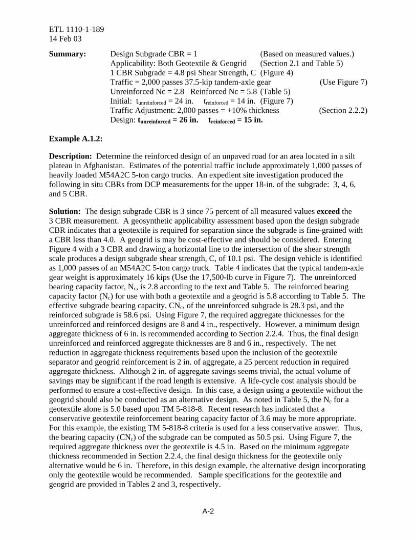
Description: Determine the reinforced design of an unpaved road for an area located in a silt plateau in Afghanistan. Estimates of the potential traffic include approximately 1,000 passes of heavily loaded M54A2C 5-ton cargo trucks. An expedient site investigation produced the following in situ CBRs from DCP measurements for the upper 18-in. of the subgrade: 3, 4, 6, and 5 CBR.
Solution: The design subgrade CBR is 3 since 75 percent of all measured values exceed the 3 CBR measurement. A geosynthetic applicability assessment based upon the design subgrade CBR indicates that a geotextile is required for separation since the subgrade is fine-grained with a CBR less than 4.0. A geogrid is may be cost-effective and should be considered. Entering Figure 4 with a 3 CBR and drawing a horizontal line to the intersection of the shear strength scale produces a design subgrade shear strength, C, of 10.1 psi. The design vehicle is identified as 1,000 passes of an M54A2C 5-ton cargo truck. Table 4 indicates that the typical tandem-axle gear weight is approximately 16 kips (Use the 17,500-lb curve in Figure 7). The unreinforced bearing capacity factor, Nc, is 2.8 according to the text and Table 5. The reinforced bearing capacity factor (Nc) for use with both a geotextile and a geogrid is 5.8 according to Table 5. The effective subgrade bearing capacity, CNc, of the unreinforced subgrade is 28.3 psi, and the reinforced subgrade is 58.6 psi. Using Figure 7, the required aggregate thicknesses for the unreinforced and reinforced designs are 8 and 4 in., respectively. However, a minimum design aggregate thickness of 6 in. is recommended according to Section 2.2.4. Thus, the final design unreinforced and reinforced aggregate thicknesses are 8 and 6 in., respectively. The net reduction in aggregate thickness requirements based upon the inclusion of the geotextile separator and geogrid reinforcement is 2 in. of aggregate, a 25 percent reduction in required aggregate thickness. Although 2 in. of aggregate savings seems trivial, the actual volume of savings may be significant if the road length is extensive. A life-cycle cost analysis should be performed to ensure a cost-effective design. In this case, a design using a geotextile without the geogrid should also be conducted as an alternative design. As noted in Table 5, the Nc for a geotextile alone is 5.0 based upon TM 5-818-8. Recent research has indicated that a conservative geotextile reinforcement bearing capacity factor of 3.6 may be more appropriate. For this example, the existing TM 5-818-8 criteria is used for a less conservative answer. Thus, the bearing capacity (CNc) of the subgrade can be computed as 50.5 psi. Using Figure 7, the required aggregate thickness over the geotextile is 4.5 in. Based on the minimum aggregate thickness recommended in Section 2.2.4, the final design thickness for the geotextile only alternative would be 6 in. Therefore, in this design example, the alternative design incorporating only the geotextile would be recommended. Sample specifications for the geotextile and geogrid are provided in Tables 2 and 3, respectively.
A-2

ETL 1110-1-189 14 Feb 03
Summary: Design Subgrade CBR = 3 (Based on measured values.) Applicability: Geotextile Recommended (Equation 1) Geogrid Should Be Considered (Section 2.1 and Table 5) 3 CBR Subgrade = 10.1 psi Shear Strength, C (Figure 4) Traffic = 1,000 passes 16-kip tandem-axle gear (Use Figure 7) Unreinforced Nc = 2.8 GT-GG Reinforced Nc = 5.8 (Table 5) Initial: tunreinforced = 8 in. treinforced = 4 in. (Figure 7) Minimum Thickness Adjustment: (Section 2.2.4) Design: tunreinforced = 8 in. treinforced = 6 in. Geotextile Only Design Alternative: Nc = 5.0 (Table 5) Initial: tunreinforced = 8 in. treinforced = 4.5 in. (Figure 7) Minimum Thickness Adjustment: (Section 2.2.4) Design: tunreinforced = 8 in. treinforced = 6 in. Select Geotextile Only Alternative Based Upon Costs Example A.1.3:
Description: Determine the reinforced design of an unpaved road for an area located in the Saudi Arabian desert. Estimates of the potential traffic include approximately 1,000 passes of an M1000 HET. A site investigation revealed that 75 percent of the soil strengths in the upper 18 in. of the sand subgrade were greater than a 3 CBR.
Solution: The design subgrade CBR is 3. A geosynthetic applicability assessment based upon the design subgrade CBR indicates that a geotextile is not required for separation with a sand subgrade unless prior experience has indicated separation problems. A geogrid may be cost-effective and should be considered for use. Entering Figure 4 with a 3 CBR and drawing a horizontal line to the intersection of the shear strength scale produces a design subgrade shear strength, C, of 10.1 psi. The design vehicle is identified as 1,000 passes of an M1000 HET. Table 4 indicates that the typical tandem-axle gear weight for the design vehicle is 37 kips. The unreinforced bearing capacity factor, Nc, is 2.8 according to the text and Table 5. The reinforced bearing capacity factor (Nc) for use with a geogrid is 5.8 according to Table 5. The effective subgrade bearing capacity, CNc, of the unreinforced subgrade is 28.3 psi, and the reinforced subgrade is 58.6 psi. Using Figure 7, the required aggregate thicknesses for the unreinforced and reinforced designs are 14 and 6 in., respectively. As noted in Section 2.2.2, the design aggregate thickness should be increased by 10 percent to account for the abrasive action of the HET’s multiple heavy wheel loads. This adjustment results in adjusted design thicknesses for the unreinforced and reinforced pavements of 15 and 7 in. Thus, the final design unreinforced and reinforced aggregate thicknesses are 15 and 7 in., respectively. The net reduction in aggregate thickness requirements based upon the inclusion of the geogrid reinforcement is 8 in. of aggregate, a 53 percent reduction in required aggregate thickness. A life-cycle cost analysis should be performed 1to ensure a cost-effective design. Sample specifications for the geotextile and geogrid are provided in Tables 2 and 3, respectively.
Summary: Design Subgrade CBR = 3 (Based on measured values.)
A-3

ETL 1110-1-189 14 Feb 03
Applicability: Geotextile Not Required (Section 2.1 and Table 5) Geogrid Should Be Considered (Section 2.1 and Table 5) 3 CBR Subgrade = 10.1 psi Shear Strength, C (Figure 4) Traffic = 1,000 passes 37-kip tandem-axle gear (Use Figure 7) Unreinforced Nc = 2.8 Reinforced Nc = 5.8 (Table 5) Initial: tunreinforced = 14 in. treinforced = 6 in. (Figure 7) HET Abrasion Thickness Adjustment: (Section 2.2.2) Adjusted Design: tunreinforced = 15 in. treinforced = 7 in. Minimum Thickness Adjustment: (Section 2.2.4) Design: tunreinforced = 15 in. treinforced = 7 in.
A.2 Flexible Pavement Design Examples
Example A.2.1:
Description: Determine the reinforced design of a flexible pavement for an area located in the floodplain of the Sava River. Estimates of the potential traffic include approximately 20,000 passes of heavily loaded tandem-axle trucks, approximately 40 percent of the total expected traffic. A site investigation revealed that 75 percent of the soil strengths in the upper 18 in. of the fine-grained subgrade were greater than a 6 CBR.
Solution: The design subgrade CBR is 6. A geosynthetic applicability assessment based upon the design subgrade CBR indicates that a geogrid may be a cost-effective alternative. A geotextile for separation is generally not recommended at this design subgrade strength unless prior experience indicated significant separation problems. The next step is to determine the design traffic. The design vehicle is identified as 20,000 passes of a tandem-axle truck, which composes approximately 40 percent of the estimated traffic. The design of a conventional flexible pavement requires that several assumptions be made to determine the Design Index (DI). First, the location of the road indicates that the road will be in flat terrain. It is further assumed that the road will lie in an open area rather than in a base camp and that two-lane traffic will be required. A design hourly volume (DHV) of traffic can be assumed to range from 0 to 100 since the total traffic is only 20,000 trucks and 50,000 total vehicles. Thus, the design road is a Class E road according to TM 5-822-2. Since the traffic includes 40 percent trucks with at least 3 axles, the traffic category is Category IVA according to TM 5-822-5, Chapter 3. For a Class E road with a Traffic Category of IVA, the required design index (DI) is 5 according to Table 7. The required flexible pavement thickness is then determined using Figure 9, the design subgrade CBR, and the design index. Enter Figure 9 on the x-axis with the design subgrade CBR (6) and draw a vertical line to the intersection of the appropriate design index curve, 5 in this case. A horizontal line is then projected from the intersection with the design index curve to the y-axis to determine the total required pavement thickness. The total required pavement thickness for this example is 16 in. It is assumed that a subbase will not be used and the base course is capable of producing an 80 CBR design strength. Using this information, the minimum surface and base
A-4
ETL 1110-1-189 14 Feb 03
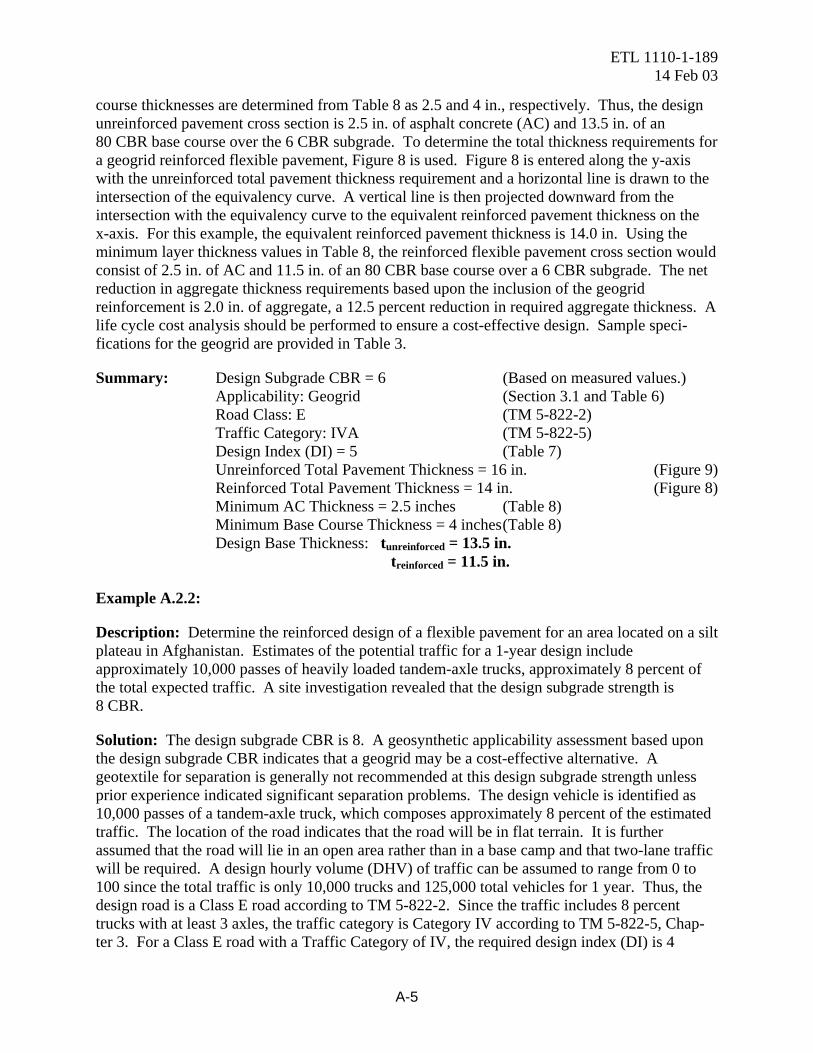
course thicknesses are determined from Table 8 as 2.5 and 4 in., respectively. Thus, the design unreinforced pavement cross section is 2.5 in. of asphalt concrete (AC) and 13.5 in. of an 80 CBR base course over the 6 CBR subgrade. To determine the total thickness requirements for a geogrid reinforced flexible pavement, Figure 8 is used. Figure 8 is entered along the y-axis with the unreinforced total pavement thickness requirement and a horizontal line is drawn to the intersection of the equivalency curve. A vertical line is then projected downward from the intersection with the equivalency curve to the equivalent reinforced pavement thickness on the x-axis. For this example, the equivalent reinforced pavement thickness is 14.0 in. Using the minimum layer thickness values in Table 8, the reinforced flexible pavement cross section would consist of 2.5 in. of AC and 11.5 in. of an 80 CBR base course over a 6 CBR subgrade. The net reduction in aggregate thickness requirements based upon the inclusion of the geogrid reinforcement is 2.0 in. of aggregate, a 12.5 percent reduction in required aggregate thickness. A life cycle cost analysis should be performed to ensure a cost-effective design. Sample speci-fications for the geogrid are provided in Table 3.
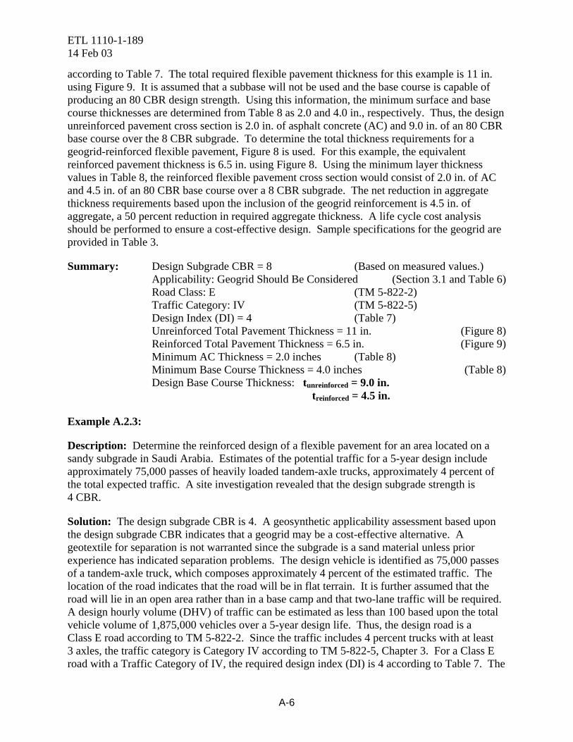
Summary: Design Subgrade CBR = 6 (Based on measured values.) Applicability: Geogrid (Section 3.1 and Table 6) Road Class: E (TM 5-822-2) Traffic Category: IVA (TM 5-822-5) Design Index (DI) = 5 (Table 7) Unreinforced Total Pavement Thickness = 16 in. (Figure 9) Reinforced Total Pavement Thickness = 14 in. (Figure 8) Minimum AC Thickness = 2.5 inches (Table 8) Minimum Base Course Thickness = 4 inches (Table 8) Design Base Thickness: tunreinforced = 13.5 in. treinforced = 11.5 in. Example A.2.2:
Description: Determine the reinforced design of a flexible pavement for an area located on a silt plateau in Afghanistan. Estimates of the potential traffic for a 1-year design include approximately 10,000 passes of heavily loaded tandem-axle trucks, approximately 8 percent of the total expected traffic. A site investigation revealed that the design subgrade strength is 8 CBR.
Solution: The design subgrade CBR is 8. A geosynthetic applicability assessment based upon the design subgrade CBR indicates that a geogrid may be a cost-effective alternative. A geotextile for separation is generally not recommended at this design subgrade strength unless prior experience indicated significant separation problems. The design vehicle is identified as 10,000 passes of a tandem-axle truck, which composes approximately 8 percent of the estimated traffic. The location of the road indicates that the road will be in flat terrain. It is further assumed that the road will lie in an open area rather than in a base camp and that two-lane traffic will be required. A design hourly volume (DHV) of traffic can be assumed to range from 0 to 100 since the total traffic is only 10,000 trucks and 125,000 total vehicles for 1 year. Thus, the design road is a Class E road according to TM 5-822-2. Since the traffic includes 8 percent trucks with at least 3 axles, the traffic category is Category IV according to TM 5-822-5, Chap-ter 3. For a Class E road with a Traffic Category of IV, the required design index (DI) is 4
A-5
ETL 1110-1-189 14 Feb 03
according to Table 7. The total required flexible pavement thickness for this example is 11 in. using Figure 9. It is assumed that a subbase will not be used and the base course is capable of producing an 80 CBR design strength. Using this information, the minimum surface and base course thicknesses are determined from Table 8 as 2.0 and 4.0 in., respectively. Thus, the design unreinforced pavement cross section is 2.0 in. of asphalt concrete (AC) and 9.0 in. of an 80 CBR base course over the 8 CBR subgrade. To determine the total thickness requirements for a geogrid-reinforced flexible pavement, Figure 8 is used. For this example, the equivalent reinforced pavement thickness is 6.5 in. using Figure 8. Using the minimum layer thickness values in Table 8, the reinforced flexible pavement cross section would consist of 2.0 in. of AC and 4.5 in. of an 80 CBR base course over a 8 CBR subgrade. The net reduction in aggregate thickness requirements based upon the inclusion of the geogrid reinforcement is 4.5 in. of aggregate, a 50 percent reduction in required aggregate thickness. A life cycle cost analysis should be performed to ensure a cost-effective design. Sample specifications for the geogrid are provided in Table 3.
Summary: Design Subgrade CBR = 8 (Based on measured values.) Applicability: Geogrid Should Be Considered (Section 3.1 and Table 6) Road Class: E (TM 5-822-2) Traffic Category: IV (TM 5-822-5) Design Index (DI) = 4 (Table 7) Unreinforced Total Pavement Thickness = 11 in. (Figure 8) Reinforced Total Pavement Thickness = 6.5 in. (Figure 9) Minimum AC Thickness = 2.0 inches (Table 8) Minimum Base Course Thickness = 4.0 inches (Table 8) Design Base Course Thickness: tunreinforced = 9.0 in. treinforced = 4.5 in. Example A.2.3:
Description: Determine the reinforced design of a flexible pavement for an area located on a sandy subgrade in Saudi Arabia. Estimates of the potential traffic for a 5-year design include approximately 75,000 passes of heavily loaded tandem-axle trucks, approximately 4 percent of the total expected traffic. A site investigation revealed that the design subgrade strength is 4 CBR.
Solution: The design subgrade CBR is 4. A geosynthetic applicability assessment based upon the design subgrade CBR indicates that a geogrid may be a cost-effective alternative. A geotextile for separation is not warranted since the subgrade is a sand material unless prior experience has indicated separation problems. The design vehicle is identified as 75,000 passes of a tandem-axle truck, which composes approximately 4 percent of the estimated traffic. The location of the road indicates that the road will be in flat terrain. It is further assumed that the road will lie in an open area rather than in a base camp and that two-lane traffic will be required. A design hourly volume (DHV) of traffic can be estimated as less than 100 based upon the total vehicle volume of 1,875,000 vehicles over a 5-year design life. Thus, the design road is a Class E road according to TM 5-822-2. Since the traffic includes 4 percent trucks with at least 3 axles, the traffic category is Category IV according to TM 5-822-5, Chapter 3. For a Class E road with a Traffic Category of IV, the required design index (DI) is 4 according to Table 7. The
A-6

ETL 1110-1-189 14 Feb 03
total required flexible pavement thickness for this example is 18.5 in. using Figure 9. It is assumed that a 10-CBR subbase will be used with a base course capable of producing an 80 CBR design strength. Since a subbase layer is to be used, Figure 9 must be used to determine the aggregate thickness requirements above the 10-CBR subbase. Entering Figure 9 with 10 CBR, the required pavement thickness above the subbase is 10.0 in. Using this information, the minimum surface and base course thicknesses are determined from Table 8 as 2.0 and 4.0 in., respectively. Thus, the design unreinforced pavement cross section is 2.0 in. of asphalt concrete (AC) and 8.0 in. of an 80 CBR base course over 8.5 in. of the 10 CBR subbase. To determine the total thickness requirements for a geogrid-reinforced flexible pavement, Figure 8 is used. For the 10-in. combined surface and base course thickness, the equivalent reinforced pavement thickness is 6.0 in. using Figure 8. Thus, the geogrid reinforcement material is placed at the subbase-base interface. Using the minimum layer thickness values in Table 8, the reinforced flexible pavement cross section would consist of 2.0 in. of AC and 4.0 in. of an 80 CBR base course over a 8.5 in. of a 10-CBR subgrade. The net reduction in aggregate base thickness requirements based upon the inclusion of the geogrid reinforcement is 4.0 in. of aggregate, a 50 percent reduction in required aggregate base thickness. A life cycle cost analysis should be performed to ensure a cost-effective design. Sample specifications for the geogrid are provided in Table 3.
Summary: Design Subgrade CBR = 4 (Based on measured values.) Applicability: Geotextile Not Warranted (Section 3.1 and Table 6) Geogrid Should Be Considered (Section 3.1 and Table 6) Road Class: E (TM 5-822-2) Traffic Category: IV (TM 5-822-5) Design Index (DI) = 4 (Table 7) Unreinforced Total Pavement Thickness = 18.5 in. (Figure 9) Unreinforced Subbase Thickness = 8.5 in. (Figure 9) Reinforced Total Pavement Thickness = 14.5 in. (Figure 8) Minimum AC Thickness = 2.0 inches (Table 8) Minimum Base Course Thickness = 4.0 inches (Table 8) Design Base Course Thickness: tunreinforced = 8.0 in. treinforced = 4.0 in.
A-7