Embed Size (px)
Citation preview

URemedial Investigation Work Plan NYSDEC Site #C738046 Location:
Former Breneman Site 8 East Utica Street Oswego, New York Prepared for:
Canalview Development, LLC 70 East First Street Oswego, New York 13126 8BLaBella Project No. 212038 Revised June 2013

URemedial Investigation Work Plan NYSDEC Site #C738046
Location:
Former Breneman Site 8 East Utica Street
Oswego, New York
Prepared for:
Canalview Development, LLC 70 East First Street
Oswego, New York 13126
9BLaBella Project No. 212038
Revised June 2013
LaBella Associates, P.C. 300 State Street Rochester, New York 14614

Certification
This work plan documents the proposed remedial investigation work to be performed at the Former Breneman Site, located at 8 East Utica Street, City of Oswego, Oswego County, New York (BCP Site #C738046). I, David K. Engert, CHMM, certify that I am currently a Qualified Environmental Professional as defined in 6 NYCRR Part 375 and that this Remedial Investigation Work Plan was prepared in accordance with all applicable statutes and regulations and in substantial conformance with the DER Technical Guidance for Site Investigation and Remediation (DER-10). David K. Engert, CHMM June 5, 2013 Printed Name Date
Signature

Table of Contents Page 1.0 Introduction ............................................................................................................................ 1 2.0 Site Description & History ..................................................................................................... 1 3.0 Summary of Areas of Concern ............................................................................................... 4 4.0 Objectives, Scope & Rationale ............................................................................................... 4 5.0 Remedial Investigation Work ................................................................................................. 5 5.1 Field Activities Plan .................................................................................................... 5 5.2 Quality Assurance/Quality Control Plan .................................................................. 13 5.3 Electronic Data Submission ...................................................................................... 14 6.0 Health and Safety Plan ......................................................................................................... 14 7.0 Reporting & Schedule .......................................................................................................... 14 8.0 Citizen Participation Activities ............................................................................................ 14 10BUFigures 11BFigure 1 Site Location Map 12BFigure 2 Site Plan 13BFigure 3 Previous Investigation Locations 14BFigure 4 Area of Concern Locations 15BFigure 5 Proposed RIWP Sample Locations 16BTable 1 Previous Investigation Sample Data 17BAppendix 1 – Contact List Information and Qualifications 18BAppendix 2 – Site Specific Community Air Monitoring Plan 19BAppendix 3 – Quality Control Program 20BAppendix 4 – Health & Safety Plan Appendix 5 – Anticipated Project Schedule
- 1 - Remedial Investigation Work Plan
NYSDEC Site #C738046 Former Breneman Site, Oswego, New York
LaBella Project No. 212038
0B1.0 Introduction
LaBella Associates, P.C. (LaBella) is pleased to submit this Remedial Investigation Work Plan (RIWP) to characterize soil and groundwater conditions at Site located at 8 East Utica Street, City of Oswego, Oswego County, New York, herein after referred to as the “Site”. A Site Location Map is included as Figure 1. LaBella is submitting this RIWP on behalf of Canalview Development, LLC (Canalview). Canalview intends to investigate the nature and extent of environmental impacts at the Site. As such, Canalview entered the Site into the New York State Department of Environmental Conservation (NYSDEC) Brownfield Cleanup Program (BCP) to conduct a Remedial Investigation (RI).
1B2.0 Site Description and History
The Site consists of approximately 2.1044 acres. Figure 2 attached illustrates the location and surrounding area of the Site. The Site has been vacant since 1998. The Project Site and a property adjacent to the west were historically used for manufacturing purposes beginning in 1834. From that time period until 1954, the Project Site ownership changed several times until purchased by Breneman of Wisconsin, Inc. (“Breneman”). Breneman used the Site for the manufacturing of window shades utilizing paints, organic solvents, dyes and phthalates in its manufacturing processes. Both aboveground and underground storage tanks (ASTs and USTs) were maintained on the Site. Manufacturing operations continued at the Project Site until approximately 1981. Transformers containing PCBs were observed leaking from the Site and were removed in 1989. In 1990, a fire destroyed most of the Project Site buildings. Between 1996 and 1998, the City of Oswego undertook emergency demolition operations of the remaining buildings located at the Project Site. In an effort to minimize demolition costs, demolished building materials were backfilled onto the Site, however, no post-demolition soil analytical data was included in the 1998 demolition closeout letter. In 2005, the United States Environmental Protection Agency (USEPA) conducted surface and subsurface soil sampling at the Project Site. Results of this sampling indicated the presence of PAHs, pesticides, arsenic, lead, and mercury at concentrations that exceed New York State Department of Environmental Conservation Soil Cleanup Objectives. In March 2006, the EPA determined that no further remedial action by the Federal Superfund program was warranted. The below summarized previous environmental work/reports are associated with the Site [Note: The information below was provided previously to NYSDEC Region 7.]:
• Final Site Remediation Report Breneman Building, Environmental Products and Services, Inc. (EPS), 1990 – This report indicates that the NYSDEC retained EPS in response to a Spill that was reported associated with transformer oil at the Site. EPS’s report indicates that approximately 35-gallons of oil had been released from a transformer; EPS reportedly cleaned up the oil with absorbent materials (i.e., Speedy Dry) and disposed of all impacted materials off-site. In addition, EPS removed five (5) transformers that had contained PCB-oil and three (3) transformers that had contained non-PCB oil as well as roofing material from Building 2 that had

- 2 - Remedial Investigation Work Plan
NYSDEC Site #C738046 Former Breneman Site, Oswego, New York
LaBella Project No. 212038
been contaminated from a leaking PCB-oil transformer (the transformer had been located on the roof). EPS noted that the PCB-oil appeared to have leaked onto the roofing material, down the side of the building and onto soil next to Building 2. It should be noted that Building 2 is located within the current BCP Site boundary (refer to Figure 2).
• Final Draft Site Inspection Report, Halliburton NUS Environmental Corporation, 1991 – This limited report was prepared for the USEPA Environmental Services Division. The report identified the former use of organic solvents including acetone and methyl ethyl ketone (MEK) during historical industrial operations at the Site. Halliburton NUS recommended the Site be listed as “Higher Priority for Further Action” based on the presence of asbestos within the Site buildings.
• Preliminary Environmental Assessment of the Former Breneman Building O’Brien and Gere Engineers, Inc. (O’Brien and Gere) 1991 – This report detailed several site visits by O’Brien and Gere and a historical and regulatory record review. O’Brien and Gere’s assessment identified the following potential environmental issues at the Site:
Bulk storage tanks including four (4) ASTs used respectively for the storage of naphthalene, MEK (this AST was actually partially buried) and two (2) for heating oil as well as one (1) UST used for the storage of acetone. It should be noted that one (1) of the heating oil ASTs was located in Building 10 of the facility, which is not within the current BCP Site boundary (refer to Figure 2).
O’Brien and Gere reported the presence of approximately 30-40 drums within the Site buildings. Labels on the drums indicated they contained at least 20 different materials including, but not limited to bleaching powder, hydrogen peroxide and gear oil. The interior drums were reported to be in generally good condition. O’Brien and Gere reported the presence of five (5) drums in the vegetated area on the western portion of the BCP Site. O’Brien and Gere also indicated that additional drums may be located in this vegetated area.
The presence of on-site transformers containing PCB oil. The NYSDEC retained a contractor (EPS) to remove PCB-containing transformers in 1989 following the report of a Spill associated with a PCB-containing transformer. O’Brien and Gere had previously inventoried the transformers in 1988 and indicated in the 1991 report that the PCB-transformers had been removed from the Site by the NYSDEC-hired contractor.
The presence of miscellaneous interior items including floor staining and small (up to 2-gallons) oil reservoirs.
• Breneman Site Development Projects, Phase I Report, Nussbaumer and Clarke, Inc., 1996 – The
report comprises a structural analysis of the Site buildings subsequent to a major fire at the facility. Nussbaumer and Clarke, Inc., recommend the emergency demolition of the Site building and the containment and abatement of asbestos containing materials.
• Site Prioritization Report, Weston Solutions Inc., (Weston) 2005 – This report indicates that “suitable” demolished building material had been used as fill during the emergency demolition of the Site buildings in 1996 through 1998. Documentation does not appear to exist which indicates if potentially impacted (e.g., stained) building materials were used as fill at the Site. The report also details a subsurface investigation conducted at the Site in January 2005 by the USEPA Region 2 Site Assessment Team. This investigation included the collection of surface

- 3 - Remedial Investigation Work Plan
NYSDEC Site #C738046 Former Breneman Site, Oswego, New York
LaBella Project No. 212038
and subsurface samples from the Site. Fourteen (14) direct-push soil borings were advanced, of which twelve (12) were completed within the BCP Site boundary. A total of fourteen (14) subsurface soil samples and three (3) surface soil samples were collected within the BCP Site boundary. One (1) subsurface sample (SS-02) appears to have been collected specifically in the vicinity of former transformers. Each soil sample was analyzed for volatile organic compounds (VOCs), semi-volatile organic compounds (SVOCs), pesticides, PCBs and metals. This investigation did not find evidence of PCBs but did identify pesticides, metals and SVOCs in surface and subsurface soils. The sample locations are depicted on Figure 3 and the sample data generated samples collected within the BCP Site boundary have been summarized in Tables 1A through 1D, which compare the sample data to current New York State Soil Cleanup Objectives (SCOs). In addition to this investigation, Weston’s report notes that two (2) standing water samples were collected from test pits during previous earthwork construction in 1998. This work was completed by NFCS Environmental and Safety Consultants in 1998. Analysis of these water samples detected elevated concentrations (i.e., above NYSDEC Technical and Operation Guidance Series 1.1.1 Groundwater Standards) of methylene chloride and o-xylene in one of the test pits. It should be noted that both test pits were excavated along the Oswego Canal and not within the current BCP Site boundary (refer to Figure 3). Groundwater samples do not appear to have been collected within the BCP Site boundary.
USummary of Geologic and Hydrogeologic Conditions
This discussion of on-site overburden geology is based upon limited information obtained from the review of previous environmental investigations of the Site.
• The northeastern portion of the Site is reportedly covered by the concrete floor slab from the former Site building (refer to Figure 2).
• Soil boring logs were not included in the previous environmental reports. However, based on the review of soil sample descriptions from Weston’s 2005 report, the composition of subsurface soils within the BCP Site boundary vary greatly but appear to include silty sand, clayey silt and sandy clay with varying amounts of gravel. These sample descriptions note the presence of saturated soils at approximately 8-feet (ft.) below ground surface (bgs) on the western-most portion of the BCP Site in which ground elevations are lowest. Saturated soils were not noted by Weston in sample descriptions collected from the upper (i.e., eastern) portion of the BCP Site.
• Based on the reported use of “suitable” building materials for fill during the emergency demolition of Site buildings in 1996 through 1998, a considerable amount of fill material including bricks, concrete and ash are expected to be located at the Site. The locations in which building materials were used as fill have not been documented. However, it should be noted that asbestos abatement was performed prior to and during the emergency demolition and as such, asbestos containing materials are not anticipated to be encountered during the proposed RI work at the Site.
• Although groundwater monitoring wells have not been installed at the Site, groundwater flow beneath the Site is likely to the west, based on the close proximity of the Oswego River and Oswego Canal to the BCP Site. The river and canal are located approximately 100-ft. to the west of the BCP Site boundary (refer to Figure 1).

- 4 - Remedial Investigation Work Plan
NYSDEC Site #C738046 Former Breneman Site, Oswego, New York
LaBella Project No. 212038
2B3.0 Summary of Areas of Concern
Based on the information obtained from the previous environmental investigations detailed in Section 2.0, there appear to be two (2) Areas of Concern (AOCs) that should be evaluated as part of the RI. A brief summary of each AOC is presented below and the approximate AOC locations are depicted on Figure 4:
• AOC #1: Underground Storage Tanks
Previous investigations have identified the former presence of two (2) USTs at the Site; one (1) 5,000-gallon acetone UST and one (1) 10,000-gallon methyl ethyl ketone (MEK) UST that was partially buried in a hillside. These USTs were both reportedly located on the northern portion of the Site, to the west of Building 4C (refer to Figure 4). Based on Weston’s report, these USTs have been removed from the Site, although documentation which would indicate the time of removal or the status of any post-excavation samples has not been identified.
• AOC #2: Historic Waste Disposal and Fill Material
Based on the long term industrial use of the Site and the known use of building materials as fill material during the emergency demolition of the former Breneman facility in 1996 through 1998, there exists the potential for subsurface impacts at the Site. The previous limited subsurface investigation has identified the presence of pesticides, metals and SVOCs in surface and subsurface soils at concentrations exceeding New York Codes, Rules and Regulations (NYCRR) Part 375-6.8(a) Unrestricted Use Soil Cleanup Objectives (SCOs) (refer to Tables 1A through 1D). The presence of these compounds appears associated with historic waste disposal and filling at the Site and have not been completely delineated. In addition, O’Brien and Gere’s 1991 report noted that several drums were observed on the vegetated, sloped area on the western portion of the Site and that additional drums may have been located in that area. Subsequent investigations do not appear to have addressed these drums.
3B4.0 Objectives, Scope and Rationale
The objectives of this RIWP are to evaluate the above AOCs in order to determine the extent of remedial actions required (if any) at the Site. The investigation work will include evaluating the property boundaries, conducting a qualitative exposure assessment for actual or potential exposures to contaminants at the Site and/or emanating from the Site, and producing data that will support the development of remedial actions (if any are warranted). Based on the nature of the work, it is necessary to conduct an iterative investigation process. Specifically, the findings of the work presented in this RIWP may warrant additional delineation, which may include sampling of soil vapor, Oswego River/Canal sediments or other environmental media in order to define the nature and extent of contamination in select areas where impacts are identified above Standards, Criteria and Guidance (SCGs). In this occurrence, addendum work plans may be submitted to NYSDEC for review and approval in order to determine the nature and extent of all impacts above SCGs. The RIWP presents a phased approach with each Task providing data to guide remaining Tasks. The sampling methodologies and locations are generally defined herein; however, actual sampling methodologies and locations may vary depending on accessibility, underground utilities and data obtained in previous tasks. NYSDEC will be contacted for approval prior to varying any sampling methodology or

- 5 - Remedial Investigation Work Plan
NYSDEC Site #C738046 Former Breneman Site, Oswego, New York
LaBella Project No. 212038
location. The current scope of work is based on previously gathered analytical data; information previously gathered regarding historical operations conducted at the Site and the project objectives. The RI work will be completed in general accordance with NYSDEC Program Policy DER-10 / Technical Guidance for Site Investigation and Remediation dated May 3, 2010 (DER-10).
4B5.0 Remedial Investigation Work
The scope of remedial investigation work is provided in this section. Appendix 4 (Quality Control Program) supplements the information provided below and includes important details concerning field activities including boring and well installations, sample collection, custody, sample handling, logs, notebook and photographic documentation, use and calibration of field instruments, decontamination, and other items. 5.1 Field Activities Plan
The field activities to be completed as part of the RIWP have been separated into seven (7) tasks and are presented below. A list with contact information of the personnel involved with the project is included in Appendix 1. Qualifications for the personnel are also included. During all ground intrusive work conducted at the Site, air monitoring will be conducted in accordance with the Site Specific Community Air Monitoring Plan (CAMP). A copy of this plan is included as Appendix 2. USampling Parameters from AOCs The protocol to determine the appropriate parameters for soil and groundwater samples collected as part of the RI are identified below. These sampling protocols will be implemented unless specific sampling parameters are identified in the specific Tasks. Soil Sampling
Every test boring completed as part of this RI will have at least one soil sample submitted for laboratory testing. In addition, samples will be submitted for laboratory testing from approximately 50% of test pits. Each soil sample will be submitted for laboratory analysis of full suite analysis, which include the following:
• USEPA Target Compound List (TCL) and NYSDEC Commissioner Policy 51 (CP-51) List volatile organic compounds (VOCs) using USEPA Method 8260;
• TCL and CP-51 List SVOCs using USEPA Method 8270; • Target Analyte List (TAL) Metals using USEPA Methods 6010 and 7471; • Total cyanide using USEPA Method 9012; • Pesticides using USEPA Method 8081; and • PCBs using USEPA Method 8082.
In the event that two apparently discrete sources are identified within the same boring or test pit, a sample of each ‘worst-case’ source will be collected/analyzed in accordance with the aforementioned

- 6 - Remedial Investigation Work Plan
NYSDEC Site #C738046 Former Breneman Site, Oswego, New York
LaBella Project No. 212038
laboratory sampling protocol. If no evidence of impairment is identified in a test boring, then one soil sample will be collected from the interval immediately above the water table or a confining substrate layer and submitted for laboratory analysis of full suite parameters.
Each soil sample collected for laboratory analysis will be labeled and preserved in accordance with Sections 5 and 7 of the Quality Control Plan (QCP) included as Appendix 3. Laboratory Quality Assurance/Quality Control (QA/QC) sampling will be performed in accordance with Section 5.2.
Groundwater Sampling
Currently, low-flow sampling methods are proposed for groundwater sample collection as part of the RI. Overburden groundwater samples will be collected using low-flow sampling techniques in accordance with USEPA Region 1 Low Stress (Low Flow) Purging and Sampling Procedure for the Collection of Groundwater Samples from Monitoring Wells, Revised January 2010. The samples will be analyzed for the full suite of parameters. Refer to Task 6 for specifics. Each groundwater sample collected for laboratory analysis will be labeled and preserved in accordance with Task 6 of this RIWP and with Sections 9 and 13 of the QCP included as Appendix 4. Laboratory Quality Assurance/Quality Control (QA/QC) sampling will be performed in accordance with Section 5.2.
Task 1: Utilities Stakeout Dig Safely New York will be contacted to initiate a utilities stakeout at the entire Site to locate any subsurface utilities in the areas in which subsurface assessment will take place. In the event that subsurface testing locations need to be adjusted due to the presence of underground utilities, the NYSDEC will be contacted to review these adjustments. Task 2: Surface Soil Evaluation Surface soil sampling will be conducted prior to significant subsurface disturbances (refer to Tasks 3 and 4) in an effort to obtain accurate and representative samples of the selected sample locations. The proposed surface sample locations are depicted on Figure 5. Currently, twelve (12) soil samples are proposed to be collected from the Site. The work to be completed as part of this task is outlined below:
• Surface soils will be collected by a hand auger and/or shovel. Each surface sample will be collected from a depth between 1-inch (in.) and 2-in. below ground surface (bgs). A sampling log will be completed for each surface sampling location which will include soil descriptions
• Soils from the surface soil locations will be screened in the field for visible impairment by capturing headspace readings from soils. Headspace readings will be analyzed with a photo-ionization detector (PID) for detectable levels of VOCs.
• Surface soil samples will be submitted for laboratory analysis of full suite parameters. The
QA/QC program (i.e., duplicate sampling, MS/MSD, DUSR, etc.) is identified in Section 5.2.

- 7 - Remedial Investigation Work Plan
NYSDEC Site #C738046 Former Breneman Site, Oswego, New York
LaBella Project No. 212038
• Each surface sample location will be located using a Global Positioning System (GPS) GeoXT
with GeoBeacon.
Task 3: Removal of Soils to Building Floor Slabs As indicated on Figure 2, the footprint of the former Site buildings comprises much of the eastern portion of the BCP Site. Approximately 2,200-square feet (sq. ft.) of concrete floor slab associated with these former buildings is visible at the ground surface on the southeastern portion of the Site. However, based on the former building footprint, approximately 22,000-sq. ft. of concrete floor slab appears to be buried under up to several feet of soil as the ground surface elevation increases toward the northeastern portion of the Site. The concrete floor slabs are anticipated to be removed during future development at the Site. As such, Task 3 is proposed to include the removal of soils currently located on the floor slabs. This soil removal will also expose the remaining approximately 22,000-sq. ft. of floor slab which will allow for a visual inspection of the slab for potential environmentally significant features such as floor drains, sumps, etc. The anticipated locations of the on-site concrete floor slab is detailed on Figure 2. It should be noted that this task will be completed subsequent to the completion of test pitting on the southern portion of the Site (i.e., the portion in which concrete floor slabs are not located) as described in Task 4. The work to be completed as part of Task 3 is outlined below: • Field oversight of this task will be provided by a Qualified Environmental Professional (QEP) or an
individual working under the direction of a QEP.
• Canalview will retain the services of a contractor to implement the removal of soils above the concrete floor slab at the Site. Prior to work on the Site, Site workers will have completed an Occupational Health and Safety Administration (OSHA) 40-hour Hazardous Waste Operations and Emergency Response (HAZWOPER) training class.
• Fencing will be placed along the perimeter of the BCP Site boundary bordering East Utica Street and East First Street.
• During the excavation work, soils will be periodically screened in the field for visible impairment and by capturing headspace readings from soils. Headspace readings will be analyzed with a photo-ionization detector (PID) for detectable levels of VOCs.
• Soils will be staged on the southern portion of the BCP Site. Prior to the excavation of soils, a shallow depression will be excavated in this area of the Site. A soil berm and silt fencing will be constructed around this depression. The staged soils will be placed within the bermed area on and covered with a minimum of double 6-mil polyethylene sheeting. The polyethylene cover will be anchored or weighted at the edges to prevent storm water and wind borne erosion. Following completion of the excavation and staging work, a barrier will be constructed around the bermed area. This barrier is anticipated to be constructed of orange snow fencing. Periodic inspections of the stockpiles, berms and covers throughout this task and the remedial program. Maintenance, repairs or replacement of materials will be conducted as necessary.

- 8 - Remedial Investigation Work Plan
NYSDEC Site #C738046 Former Breneman Site, Oswego, New York
LaBella Project No. 212038
• In the event that grossly contaminated materials (e.g., NAPLs, soils exhibiting PID readings greater than 250 ppm, etc.) or waste including drums, tanks, etc. are encountered, the NYSDEC will be contacted immediately. Grossly contaminated materials will not be moved to the staging area on the southern adjacent property.
• Water mist and other suitable methods to limit the spread of dust, dirt and vapors/odors shall be used as deemed necessary by the guidelines provided in the CAMP (Appendix 2).
• Daily inspection reports will be completed and will be included in the RI report (RIR).
• A figure depicting the area and approximate depths of excavation will be included in the RIR.
Task 4: Test Pitting Evaluation A test-pitting program will be conducted in order to evaluate the Site subsurface. This test pitting program is currently proposed to include the excavation of twelve (12) test pits in locations distributed equally throughout the Site. However, additional test pits may be completed based on any evidence of impairment observed during the evaluation as well as the presence of any potentially significant environmental features (e.g., floor drains, sumps, etc.) observed in the building floor slab to be uncovered as part of Task 3. It should be noted that the test pitting evaluation on the southern portion of the Site will be completed prior to the completion of Task 3, as noted in Task 3. In addition, test pits are currently planned to be excavated in each of the two (2) former transformer areas within the BCP Site boundary. The proposed test pit locations are included in Figure 5. [Note: in the event that the surface grades at proposed test pit locations are too steep for excavation equipment to access, a request will be made to the NYSDEC to substitute a surface soil sample in these locations]
The work to be completed as part of this task is outlined below:
• Canalview will retain the services of a contractor to implement the removal of soils above the concrete floor slab at the Site using a backhoe or excavator. Prior to work on the Site, Site workers will have completed an OSHA 40-hour Hazardous Waste Operations and Emergency Response HAZWOPER training class.
• Each test pit excavated at the Site will be advanced to equipment refusal (currently estimated to be approximately 8-ft. bgs.). The majority of these test pits are to be completed through the former building concrete floor slabs.
• In the event that a UST is encountered in a test pit, the NYSDEC will be notified immediately and
the contents of any USTs will be addressed. In accordance with DER-10, the first priority during site investigation is that contaminants in all media should be contained or stabilized to reduce or eliminate, to the extent possible, receptor exposure to contaminants or to contain further movement of contaminants through any pathway. The timely removal of the contents of any discovered USTs is intended to reduce the potential for migration of contaminants within the confines of the Site as well as reducing the potential for human health related exposure.
USTs encountered in test pits will be removed in accordance with the requirements of DER-10 to facilitate a more complete investigation.
- 9 - Remedial Investigation Work Plan
NYSDEC Site #C738046 Former Breneman Site, Oswego, New York
LaBella Project No. 212038
• Soils from the test pits will be screened in the field for visible impairment by capturing headspace readings from soils. Headspace readings will be analyzed with a photo-ionization detector (PID) for detectable levels of VOCs. Additionally, soils will be observed for any olfactory indications of impairment and evidence of non-aqueous phase liquids (NAPLs) during test pitting.
• Test pitting logs will be completed and include soil description, test pit dimensions, PID readings, when groundwater was encountered, etc. Test pitting logs will be generated by a QEP or an individual working under the direct supervision of a QEP and will be included in the RI Report.
• A test pitting photo log with pictures of each test pit will be included in the RI Report.
• Soil samples will be collected from the test pits based on evidence of impairment. At this time, samples from approximately 50% of any test pits completed at the BCP Site are anticipated to be submitted for laboratory analysis. However, this percentage may be adjusted based on field observations. As previously stated, the RI will be an iterative process and additional sampling may be warranted based on the initial sampling work in order to define the nature and extent of impacts. The soil-sampling program will be based on the protocols identified at the beginning of this Section. The QA/QC program (i.e., duplicate sampling, MS/MSD, DUSR, etc.) is identified in Section 5.2.
Test pits will be backfilled with native materials on a last-out, first-in basis. Additionally, all test pits will be backfilled by the end of the working day. Any impacts identified in the test pits will be addressed in IRMs or through final remedial actions as necessary. Equipment utilized in test pitting activities will be "rough" cleaned by removing any dirt from the bucket and the equipment tracks or tires. If necessary, the bucket and tracks or tires will be pressure washed after completion of the test pits. Each test pit will be located using a Global Positioning System (GPS) GeoXT with GeoBeacon. Task 5: Soil Borings, Sampling, & Analysis
As part of the overburden soil investigation, soil-boring data will be collected for the geologic characterization of the Site and to allow further delineation of contamination, horizontally and vertically. Soil borings will be completed in accordance with Section 6 of the QCP included as Appendix 3. To implement the soil borings at the Site, the following will be completed;
• Currently, six (6) soil borings are proposed to be advanced at the Site. One (1) soil boring is proposed to be advanced in AOC #1 and the remainder are proposed to be advanced in AOC #2. Final soil boring locations will be selected based on the information provided by the utility stakeout and accessibility.
• Borings will be advanced with a direct push sampling system (e.g., Geoprobe®). The use of direct push technology allows for rapid sampling, observation, and characterization of relatively shallow overburden soils. The Geoprobe® utilizes a four-foot Macro-core® sampler, with disposable polyethylene sleeves. Soil cores will be retrieved in four-foot sections, and can be easily cut from the polyethylene sleeves for observation and sampling.
• Borings will be advanced to equipment refusal or until a significant aquitard (e.g., bedrock, till) is encountered.
- 10 - Remedial Investigation Work Plan
NYSDEC Site #C738046 Former Breneman Site, Oswego, New York
LaBella Project No. 212038
• The drilling equipment which comes into contact with soil (e.g., core barrels, drilling rods, split spoon samplers, etc.) will be required to be decontaminated prior to use, including an alconox and potable water wash followed by a potable water rinse. In between each boring, decontamination procedures will be repeated. See Section 12 of the QCP for additional details regarding decontamination procedures.
• Soils from the borings will be continuously screened in the field for visible impairment, olfactory indications of impairment, evidence of NAPLs, and/or indication of detectable VOCs with a PID collectively referred to as “evidence of impairment.” Field screening (visual & olfactory observation, PID readings, etc.) will be recorded on a soil-boring log (or ‘PID Log’) and will be included in the Remedial Investigation Report.
• Soil Boring Logs will be completed and include soil descriptions, soil boring numbers and locations, PID readings, etc. Soil Boring Logs will be generated by a QEP or an individual working under the direct supervision of a QEP and will be included in the RI Report. If appropriate based on observed conditions, a soil boring photo log with pictures of select soil profiles from individual soil borings will be included in the RI report.
• At least one (1) soil sample will be collected from each soil boring. The soil-sampling program will be based on the protocols identified at the beginning of this Section. As previously stated, the RI will be an iterative process and additional sampling may be warranted based on the initial sampling work in order to define the nature and extent of impacts.
• Soil generated during soil sampling activities will be containerized in 55-gallon drums, characterized, and disposed of off-Site in accordance with applicable regulations. See Section 11 of the QCP for additional details regarding the management of investigation-derived wastes at the Site.
Task 6: Groundwater Investigation, Sampling, and Analysis This task includes the installation, development and sampling of overburden groundwater monitoring wells. As required by DER-10, a groundwater sample will be collected and analyzed for the full suite of parameters from each monitoring well (assuming adequate sample volumes can be obtained). The current proposed locations of overburden monitoring wells are provided on Figure 5. One (1) overburden groundwater monitoring well is proposed to be installed in each of the six (6) soil borings described in Task 5. One (1) monitoring well is proposed to be installed in AOC #1 and the remainder are proposed to be installed in AOC #2.
As part of this task, the following work will be implemented: UInstallation of Overburden Groundwater Monitoring Wells Using Geoprobe® Technology At each overburden monitoring well location, overburden soils will be collected using Macrocore samplers from the ground surface to equipment refusal (i.e., assumed bedrock). Soil will be screened in the field for “evidence of impairment” (as defined in Task 5 above).
Subsequent to collection of soil samples, overburden monitoring wells will be installed utilizing 4.25-inch hollow stem augers. Each well will be constructed with 5 to 10-ft. of 2-in. Schedule 40 0.010-slot well screen connected to an appropriate length of 2-in. schedule 40 PVC well riser to complete the well. The annulus around the screen section will be sand packed with quartz sand to approximately 1 to 2-feet

- 11 - Remedial Investigation Work Plan
NYSDEC Site #C738046 Former Breneman Site, Oswego, New York
LaBella Project No. 212038
above the screen section. The remaining annulus will be bentonite sealed to approximately 1 to 2-feet below ground surface, and then grouted to ground surface. Each well will be completed with a flush mount well cover. Additional details on the installation of groundwater monitoring wells are included in Section 6 of the QCP included as Appendix 4.
As indicated in Task 5, soil generated during drilling activities will be containerized in 55-gallon drums, characterized, and disposed of off-Site in accordance with applicable regulations. See Section 11 of the QCP for additional details regarding the management of investigation-derived wastes at the Site.
UDevelopment of Overburden Groundwater Monitoring Wells Initially, each monitoring well will be developed by removing the approximate volume of water introduced during drilling (if any) and an additional five (5) well volumes. Well development will be performed using dedicated bailers and/or pumping equipment (depending on volumes), and will continue until groundwater turbidity reaches 50 National Turbidity Units (NTUs), or lower. In the event that 50 NTUs is not reached after removing a reasonable number of well volumes (10), the NYSDEC will be contacted to request ceasing development. If dedicated equipment is not used, then the equipment will be decontaminated between each well (alconox wash with potable water rinse). If the NYSDEC Project Manager agrees that removal of this volume of water is impractical, then LaBella will work with NYSDEC to develop an alternate well development protocol. If necessary, the groundwater sampling schedule will also be adjusted. Any changes to the well development protocol or the sampling schedule will be documented in the monthly progress reports. Well development details are included in Section 6 of the QCP included as Appendix 4. Groundwater generated during well development activities will be containerized in 55-gallon drums, characterized, and disposed of off-site in accordance with applicable regulations. ULow Flow Sampling of Overburden Groundwater Monitoring Wells At least 2 weeks after development, groundwater samples will be collected from each monitoring well installed as part of the RI. Static water level (SWL) measurements will be collected from the wells immediately prior to purging. Low flow sampling of the monitoring wells will occur in order to minimize groundwater drawdown and to obtain a representative sample of groundwater conditions. In order to accomplish this task, the following steps will be taken:
1. The following low flow equipment will be utilized to conduct low flow groundwater sampling. This equipment includes:
QED Sample Pro Bladder Pump Horiba U-22 Water Quality Monitoring System Air Compressor QED MP10 Low Flow Controller ~200’ of ¼” Polyethylene Tubing
2. Low flow purging of the monitoring wells will include collection of water quality indicator
parameters. Water quality indicator parameters will be recorded at five (5)-minute intervals during the purging of the well. These water quality indicator parameters will include:
Water Level Drawdown

- 12 - Remedial Investigation Work Plan
NYSDEC Site #C738046 Former Breneman Site, Oswego, New York
LaBella Project No. 212038
Temperature pH Dissolved Oxygen Specific Conductance Oxidation Reduction Potential Turbidity
3. Groundwater sampling will commence once the groundwater quality indicator parameters
have stabilized for at least three (3) consecutive readings for the following parameters:
Water Level Drawdown <0.3’ Temperature - +/- 3% pH - +/- 0.1unit Dissolved Oxygen - +/-10% Specific Conductance - +/-3% Oxidation Reduction Potential - +/-10 millivolts Turbidity - +/-10% for values greater than 1 NTU
4. Each overburden monitoring well will be sampled for the full suite of parameters. However,
if the recoverable groundwater will not be adequate for all testing parameters, parameters will be collected based on the following hierarchy – 1) VOCs, 2) Metals, 3) SVOCs, 4) PCBs, 5) Pesticides.
5. Approximately three (3) months after the initial sampling event, a second round of
groundwater samples will be collected from the overburden monitoring wells installed as part of the RI. The sampling parameters for the second round of sampling will also be the full suite of parameters. [Note: In the event that minimal or no impacts are identified in the first round of sampling, NYSDEC may be petitioned to reduce the sampling parameter list.]
Additionally, the following items will be completed as part of Task 6:
• Monitoring well construction logs, monitoring well development logs and groundwater sampling
logs will be generated by a QEP or an individual working under the direct supervision of a QEP and will be included in the RI Report.
• Laboratory Quality Assurance/Quality Control (QA/QC) sampling will be performed in accordance with Section 5.2. An analytical data package for the first round of groundwater monitoring data will be prepared and presented to the NYSDEC.
• Groundwater contour mapping will be developed using the SWLs collected immediately prior to the two (2) groundwater sampling rounds. This mapping will be included in the Final RI report.
• Each of the monitoring wells will be surveyed for elevation. In addition, the wells will be located using a GPS GeoXT with GeoBeacon. See Section 6.1.9 of the QCP for additional survey information.

- 13 - Remedial Investigation Work Plan
NYSDEC Site #C738046 Former Breneman Site, Oswego, New York
LaBella Project No. 212038
Task 7: Qualitative Exposure Assessment
The Qualitative Exposure Assessment will be performed in accordance with Section 3.3 and Appendix 3B of DER-10. This Qualitative Exposure Assessment will evaluate whether potential or completed exposure pathways exist. This assessment will be based on the soil and groundwater sampling data generated during the RI work. Currently, it is not anticipated that off-site samples will need to be collected, rather the on-site data will be used to assess whether impacts approach or have migrated beyond the Site boundary. The Qualitative Exposure Assessment will include the following areas of evaluation:
• Source Areas – AOCs with identified impacts will be included as part of the exposure assessment. • Fate & Transport – The property boundary data will be evaluated for potential off-site migration
via soil, groundwater, and/or soil gas. • Route of Exposure – The results of Site sampling will be interpreted to determine if contaminant
concentrations are at levels that have the potential to be inhaled or ingested. • Receptor Population – The Site will be evaluated to determine the size and makeup of potential
receptors both on-site and off-site locations downgradient of the Site. These receptors include construction workers, utility workers, residents, neighbors, etc.).
• A Fish and Wildlife Resources Impact Analysis (FWRIA) Part 1: Resource Characterization will be completed for the Site due to the fact that the Oswego River and Lake Ontario are in close proximity to the Site. The results of the FWRIA Part 1 will be submitted to NYSDEC for a determination of whether a FWRIA Part 2: Ecological Impact Assessment is necessary. In the event that FWRIA Part 1 indicates that the ecological impact assessment is necessary, a separate work plan for the additional assessment meeting the requirements of Section 3.10.2 of DER-10 will be submitted under separate cover. This work plan may include the collection of off-site samples, if deemed necessary.
5.2 Quality Assurance/Quality Control Plan
Activities completed at the Site will be managed under LaBella’s Quality Control Program, which is included in Appendix 3. Laboratory QA/QC sampling will include analysis of sample blanks as follows: one trip blank and one routine field blank for each sampling methodology (e.g., soil borings, test pits, etc.) and matrix type (i.e., soil and groundwater). The blanks will be provided at a rate of one per 20 samples collected for each parameter group, or one per shipment, whichever is greater. Additionally, one (1) Matrix Spike/Matrix Spike Duplicate (MS/MSD) and one (1) duplicate sample will be collected and analyzed for each twenty samples collected for each parameter group, or one per shipment, whichever is greater. Duplicate samples will be submitted to the laboratory as blind duplicates. The MS/MSD and duplicate samples will be analyzed for the same parameters as that of the field samples. The samples will be delivered under Chain of Custody procedures to a New York State Department of Health (NYSDOH) Environmental Laboratory Approval Program (ELAP)-certified laboratory. The laboratory will provide a NYSDEC Analytical Services Protocol (ASP) Category B Deliverables data package for all samples. A DUSR will be completed for all ASP-B and ASP-B format laboratory data packages per DER-10. The DUSRs will include the laboratory data summary pages showing corrections made by the data validator and each page will be initialed by the data validator. The laboratory data summary pages will be included even if no changes were made.

- 14 - Remedial Investigation Work Plan
NYSDEC Site #C738046 Former Breneman Site, Oswego, New York
LaBella Project No. 212038
Table 4 QA/QC Sampling Plan
5.3 Electronic Data Submission
All laboratory data will be submitted in an electronic data deliverable (EDD) compatible with the database software application EQuISTM from EarthSoft® Inc.
5B6.0 Health and Safety Plan
A Site specific Health and Safety Plan (HASP) has been developed for the Site and is included in Appendix 4. LaBella will ensure that all contractors working at the Site comply with a suitable HASP as well. A copy of each contractor’s HASP will be submitted to NYSDEC prior to mobilization to the Site.
6B7.0 Reporting and Schedule
Subsequent to completing the work outlined above, a Final Remedial Investigation Report will be developed in general accordance with NYSDEC DER-10. The anticipated schedule for the work to be completed is included in Appendix 5. This schedule is dependent on NYSDEC approvals and does not account for potential delays due to public comments, weather conditions, etc. Monthly Progress Reports will be submitted by the 10th day of each month as described in the Brownfield Cleanup Agreement for this Site. The progress reports will include all preliminary analytical data and validated data that are received prior to the 10th of each month. Additionally, the validated data will be provided no more than two (2) months after the preliminary data.
7B8.0 Citizen Participation Activities
A citizen participation plan (CPP) has been developed for the project under separate cover and is on file at the document repositories. The CPP activities that will be conducted throughout the RI work include:
QA/QC Sampling Plan
Matrix Trip Blanks Field Blanks Duplicates MS/MSD
Test Pit Soil 1 per 20 samples, or one per shipment
1 per 20 samples, or one per shipment
1 per 20 samples, or one per shipment
1 per 20 samples, or one per shipment
Geoprobe Soil 1 per 20 samples, or one per shipment
1 per 20 samples, or one per shipment
1 per 20 samples, or one per shipment
1 per 20 samples, or one per shipment
Surface Soil 1 per 20 samples, or one per shipment
1 per 20 samples, or one per shipment
1 per 20 samples, or one per shipment
1 per 20 samples, or one per shipment
Overburden Monitoring Well
Groundwater
1 per 20 samples, or one per shipment
1 per 20 samples, or one per shipment
1 per 20 samples, or one per shipment
1 per 20 samples, or one per shipment

- 15 - Remedial Investigation Work Plan
NYSDEC Site #C738046 Former Breneman Site, Oswego, New York
LaBella Project No. 212038
• Maintaining and updating the Brownfields Site Contact List; • Maintaining and updating documents in the specified document repositories (as indicated in the
CPP); • Prepare and distribute NYSDEC approved fact sheets; • Assist and participate in public meetings (at the request of the NYSDEC); • Provide analytical results or other information to all site tenants upon request or as required by
applicable law; • Participate in weekly meetings with the monthly progress meetings (or teleconferences) with the
NYSDEC to discuss progress; • Other activities upon NYSDEC request.
I:\CANALVIEW DEVELOPMENT\212038\REPORTS\RIWP\RPT.04.09.2013.RIWP.REVISEDJUNE2013.DOCX

LaBella Associates, P.C. 300 State Street Rochester, New York 14614
Figures

4
300 STATE STREETROCHESTER, NY 14614P: (585) 454-6110F: (585)454-3066
www.labellapc.comCOPYRIGHT 2003
PROJECT/CLIENTDRAWING TITLE
DATE: 10/10/2012 DESIGNED BY:DRAWN BY:
REVIEWED BY:
Former Breneman SiteNYSDEC BCP #C738046
Remedial InvestigationWork Plan
Oswego, NY
JAJ
212038FIGURE 1
JAJJAJ
1:20,000
SITE
SITE LOCATION WITH USGS7.5 MINUTE TOPO MAP

E 1st St
E Utic
a St E River Rd
Lock Rd
E Alba
ny St
W Ut
ica St
Bldg 5
Bldg 14Bldg 15
Bldg 2
Bldg 12
Bldg 6
Bldg 4
Bldg 7
Bldg 3
Bldg 13
Bldg 14B
Bldg 8
Bldg 10
Bldg 4BBldg 4C
Bldg 11
Bldg 4A
Tower
Bldg 14A
FIGURE 2
212038
300 STATE STREETROCHESTER, NY 14614P: (585) 454-6110F: (585)454-3066
www.labellapc.comCOPYRIGHT 2003
0 50 10025Feet
µ
I:\C
anal
view
Dev
elop
men
t, LL
C\2
1203
8\D
raw
ings
\RIW
P\R
evis
ed M
ay 2
013\
Fig.
2.Si
teBo
unda
ry5-
1-13
.mxd
Remedial InvestigationWork Plan
Former Breneman Facility8 East Utica Street
City of Oswego, New York
BCP Site Boundary
1 inch = 75 feet
Note:2006 aerial photograph obtained from Oswego County.
LegendSite Boundary (Approximate)
Previous BCP Boundary
Former Building Outline

!(!(!(!(
!(
!(!(!(!(
!(
!(!(
!("/
"/
XW
!A!A
!A
#0
XW!A
!A
!A
!A XW !A!A
XW
E 1st St E River Rd
E Alba
ny St
Bldg 5
Bldg 14Bldg 15
Bldg 2
Bldg 12
Bldg 6
Bldg 4
Bldg 7
Bldg 3
Bldg 13
Bldg 14B
Bldg 8
Bldg 10
Bldg 4BBldg 4C
Bldg 11
Bldg 4A
Tower
Bldg 14A
S03
S04
S02
S01
SS06
SS10SS09
SS07
SS08
SS05
SS04
SS01
SS02
S05/SS03
FIGURE 3
212038
300 STATE STREETROCHESTER, NY 14614P: (585) 454-6110F: (585)454-3066
www.labellapc.comCOPYRIGHT 2003
0 30 6015Feet
µ
I:\C
anal
view
Dev
elop
men
t, LL
C\2
1203
8\D
raw
ings
\RIW
P\R
evis
ed M
ay 2
013\
Fig.
3.Pr
ev.In
vest
igat
ions
5-1-
13.m
xd
Remedial InvestigationWork Plan
Former Breneman Facility8 East Utica Street
City of Oswego, New York
Previous EnvironmentalTesting Locations
1 inch = 50 feet
Note:2006 aerial photograph obtained from Oswego County.
LegendXW Surface Soil Sample Location (Weston)
#0 Surface & Subsurface Soil Sample Location (Weston)
!A Subsurface Soil Sample Location (Weston)
"/ Prior Test Pit (NFCS)
!(Reported Former PCB-Transformer Location
!(Reported Former Unknown-Transformer Location
Area of Contaminated SoilIdentified in Weston Figure 3of Site Inspection and Prioritization Report
Site Boundary (Approximate)
Reported Former Tank Location
Former Building Outline

Former MEK UST
Former Acetone UST
AOC #1
AOC #2
C i t y H a l l , R o o m 3 0 0 B 3 0 C h u r c h S t r e e t , R o c h e s t e r , N Y 1 4 6 1 4 FIGURE 4
212038
300 STATE STREETROCHESTER, NY 14614P: (585) 454-6110F: (585)454-3066
www.labellapc.comCOPYRIGHT 2003
0 30 6015Feet
µ
I:\C
anal
view
Dev
elop
men
t, LL
C\2
1203
8\D
raw
ings
\RIW
P\R
evis
ed M
ay 2
013\
Fig.
4.AO
Cs.
5-1-
13m
xd.m
xd
Remedial InvestigationWork Plan
Former Breneman Facility8 East Utica Street
City of Oswego, New York
Area of Concern (AOC)Locations
LegendSite Boundary (Approximate)
AOC #1
AOC #2
Reported Former Tank Location
Former Building Outline
1 inch = 50 feet
Note:2006 aerial photograph obtained from Oswego County.

!(!(!(!(
!(
!(!(!(!(
!(
!(!(
!(
&<
&<
&<
&<
ED
ED
ED
ED
&<
ED
ED
ED
ED
#0
#0
#0
EDED
#0
#0
#0
ED
&<
#0
#0
ED ED
ED
#0
#0
#0 #0
&<
ED
ED
E 1st St E River Rd
E Alba
ny St
Bldg 5
Bldg 14Bldg 15
Bldg 2
Bldg 12
Bldg 6
Bldg 4
Bldg 7
Bldg 3
Bldg 13
Bldg 14B
Bldg 8
Bldg 10
Bldg 4BBldg 4C
Bldg 11
Bldg 4A
Tower
Bldg 14A
FIGURE 5
212038
300 STATE STREETROCHESTER, NY 14614P: (585) 454-6110F: (585)454-3066
www.labellapc.comCOPYRIGHT 2003
LegendProposed Sample Locations!A Soil Boring
&< Monitoring Well
ED Test Pit
#0 Surface Soil Sample
!(Reported Former PCB-Transformer Location
!(Reported Former Unknown-Transformer Location
Property Line (Approximate)
Reported Former Tank Location
Former Building Outline
Area of Contaminated SoilIdentified in Weston Figure 3of Site Inspection and Prioritization Report
0 30 6015Feet
µ
I:\C
anal
view
Dev
elop
men
t\212
038\
Dra
win
gs\R
IWP\
Rev
ised
Jun
e 20
13\F
ig 5
- M
AP.
2013
.06.
04.P
ropo
sed
sam
ple
loca
tions
.mxd
Remedial InvestigationWork Plan
Brownfield CleanupProgram Site C738046Former Breneman Site
8 East Utica Street
Proposed SampleLocations

LaBella Associates, P.C. 300 State Street Rochester, New York 14614
Tables

Sample Type
Soil Samples
SS09SS07
Sub‐surface
SS10
Sub‐surface Sub‐surfaceSub‐surface
S04
SurfaceSurface Sub‐surfaceSurface Surface
NYCRR Part 375‐6.8(b) Restricted Use Soil Cleanup
Objectives: Protection of Public Health: Restricted
NYCRR Part 375‐6.8(b) Restricted Use Soil Cleanup
Objectives: Protection of
d
S01 S02 S05 SS01 SS02 SS03 SS08
Sub‐surface Sub‐surface
Sample ID
NYCRR Part 375‐6.8(a) Unrestricted Use Soil Cleanup
Objectives
NYSDEC BCP ID No. C738046NYSDEC Brownfield Cleanup Program Remedial Investigation
Former Breneman SiteTable 1A
Results in Milligrams per Kilogram (mg/Kg)Summary of Detected Semi-Volatile Organic Compounds in Soil Samples
Sample Depth (bgs)
Sample Collection DateSemi Volatile Organic CompoundsAcetophenone ND<0.410 U ND<0.380 U ND<0.440 U ND<0.400 U 0.990 ND<0.350 U ND<0.360 U ND<0.400 U 0.170 J ND<0.390 U ND<1,100 U NA NA NAAcenaphthylene ND<0.410 U 0.140 J ND<0.440 U 0.083 J ND<0.350 U ND<0.350 U ND<0.360 U ND<0.400 U 0.260 J ND<0.390 U ND<1,100 U 100 100 107Acenaphthene ND<0.410 U ND<0.380 U ND<0.440 U ND<0.400 U ND<0.350 U ND<0.350 U ND<0.360 U ND<0.400 U 0.088 J ND<0.390 U ND<1,100 U 20 100 98Fluorene ND<0.410 U ND<0.380 U ND<0.440 U 0.110 J ND<0.350 U ND<0.350 U ND<0.360 U ND<0.400 U 0.220 J ND<0.390 U ND<1,100 U 30 100 386Phenanthrene 0.180 J 0.530 ND<0.440 U 0.880 ND<0.350 U ND<0.350 U ND<0.360 U ND<0.400 U 1.8 ND<0.390 U 4.7 100 100 1,000Anthracene ND<0.410 U 0.120 J ND<0.440 U 0.170 J ND<0.350 U ND<0.350 U ND<0.360 U 0.780 0.500 ND<0.390 U 0.980 J 100 100 1,000Carbazole ND<0.410 U ND<0.380 U ND<0.440 U 0.097 J ND<0.350 U ND<0.350 U ND<0.360 U ND<0.400 U 0.110 J 0.080 J ND<1,100 U NA NA NAFluoranthene 0.440 1.200 ND<0.440 U 1.300 ND<0.350 U ND<0.350 U ND<0.360 U 0.830 2.8 0.750 J 4.2 100 100 1,000Pyrene 0.390 J 1.100 ND<0.280 U 1.000 J ND<0.350 U ND<0.350 U ND<0.360 U 0.740 2.2 J 0.650 J ND<1,100 U 100 100 1,000Benzo(a)anthracene 0.220 J 0.590 ND<0.440 U 0.570 ND<0.350 U ND<0.350 U ND<0.360 U ND<0.400 U 1.3 ND<0.390 U 1.6 1 1 1Chrysene 0.270 J 0.750 ND<0.440 U 0.649 ND<0.350 U ND<0.350 U ND<0.360 U 2.1 J 1.4 0.440 1.9 1 3.9 1Bis(2‐ethylhexyl)phthalate ND<0.410 U ND<0.380 UJ ND<0.440 U 0.190 J ND<0.350 U 0.290 J ND<0.360 U 0.330 J 0.520 J 0.360 J ND<1,100 u 50* 50* 435**Benzo(b)fluoranthene 0.230 J 0.630 ND<0.440 U 0.510 ND<0.350 U ND<0.350 U ND<0.360 U 0.350 J 1.2 0.280 J 1.3 1 1 1.7Benzo(k)fluoranthene 0.240 0.690 0.170 J 0.570 ND<0.350 U ND<0.350 U ND<0.360 U ND<0.400 J 1.1 0.290 J 1.5 0.8 3.9 1.7B ( ) 0 240 J 0 690 0 180 J 0 560 ND<0 350 U ND<0 350 U ND<0 360 U ND<0 400 J 1 200 0 330 J 1 4 1 1 22
9'‐12'
1/5/2005 1/5/20051/4/2005
8‐9.5'
1/5/2005
10'‐12'9'‐11' 9'‐11'1"‐3"
1/4/2005
6'‐8'1"‐3" 1"‐3" 1"‐3" 10'‐11.5' ResidentialGroundwater
1/5/20051/4/2005 1/4/2005 1/4/2005 1/4/2005 1/4/2005
Benzo(a)pyrene 0.240 J 0.690 0.180 J 0.560 ND<0.350 U ND<0.350 U ND<0.360 U ND<0.400 J 1.200 0.330 J 1.4 1 1 22Indeno(1,2,3‐cd)pyrene 0.210 J 0.520 ND<0.440 U 0.370 J ND<0.350 U ND<0.350 U ND<0.360 U ND<0.400 U 0.770 ND<0.390 U 0.820 J 0.5 0.5 8.2Dibenzo(a,h)anthracene ND<0.410 U 0.190 J ND<0.440 U 0.093 J ND<0.350 U ND<0.350 U ND<0.360 U ND<0.400 U 0.200 J ND<0.390 U ND<1,100 u 0.33 0.33 1,000Benzo(g,h,i)perylene ND<0.410 U 0.120 J ND<0.440 U 0.130 J ND<0.350 U ND<0.350 U ND<0.360 U ND<0.400 U 0.600 ND<0.390 U ND<1,100 J 100 100 1,000
Notes:SVOC analysis by United States Environmental Protection Agency (USEPA) Method SW846 8270.Bold type indicates that the constituent was detected at a concentration above the NYCRR Part 375‐6.8(b) Standard: Protection of Groundwater SCO.Italicized type indicates that the constituent was detected at a concentration above the NYCRR Part 375‐6.8(a) Standard: Unrestricted Use SCO.Shaded type indicates that the constituent was detected at concentrations above the NYCRR Part 375‐6.8(b) Standard: Restricted Residential SCO.J – Indicates that the constituent was positively identified; but the associated numerical value is the approximate concentration of the constituent in the sample.U ‐ Indicates that the constituent was not detected.NA = Not Applicable or Not Available*Indicates no Part 375‐6 SCO for this compound; SCO from NYSDEC Commissioner Policy 51 Supplemental SCOs for Residential Facilities**Indicates no Part 375‐6 SCO for this compound; SCO from NYSDEC Commissioner Policy 51 Supplemental SCOs for Protection of Groundwater
I:\Canalview Development\212038\Reports\RIWP\Tables\Table 1 - Prior Soil Data_Revised 2013.06.05.xls
TablesFormer Breneman Site, Oswego, New York
NYSDEC BCP ID No. C738046LaBella Project No. 212038

Sample Type
SS07 SS08
Subsurface Subsurface
SS09
Subsurface
SS10
SubsurfaceSubsurface Subsurface Subsurface
Former Breneman Site
Sample ID (Depth)
Summary of Detected Target Analyte List Metals in Soil Samples
Table 1B
NYSDEC Brownfield Cleanup Program Remedial InvestigationNYSDEC BCP ID No. C738046
Results in Milligrams per Kilogram (mg/Kg)
Soil Samples
NYCRR Part 375-6.8(a) Restricted Use Soil Cleanup
Objectives: U t i t d U
NYCRR Subpart 375-6(b) Remedial
Program Soil Cleanup
Objectives for the Protection of
Public Health:
SS01 SS03SS02
NYCRR Part 375-6(b) Remedial Program Soil
Cleanup Objectives for the
Protection of Sample TypeSample Depth (bgs)
Sample Collection Date
Aluminum 3,650 3,590 3,030 3,550 2,780 4,790 11,500Antimony ND<6.3 U ND<6.3 U ND<6.5 U 3.3 J ND<6.9 U 2.5 J 6.8 UArsenic 2.8 2.8 3.7 2 2.9 4.6 4.2 13 16 16Barium 30.2 27.9 23.6 182 73.6 168 134 350 400 820Beryllium 0.22 J 0.21 J 0.18 J 0.22 J 0.17 J 0.28 J 0.67 7.2 72 47Cadmium ND<0.53 U ND<0.52 U ND<0.54 U 0.05 J ND<0.58 U 0.25 J 0.13 J 2.5 4.3 7.5Calcium 34,700 J 33,900 J 30,900 J 31,300 J 24,700 J 9,500 J 60,400 JChromium 5.4 5.7 4.8 22.1 6.3 10.6 29.2 30 180 Not listedCobalt 4.1 J 4.0 J 3.4 J 3.4 J 2.8 J 4.7 J 5.7 30*Copper 17.4 20.1 16.7 21.5 24.3 49.1 29.3 50 270 1,720Iron 9,420 9,400 8,050 7,340 7,430 12,000 23,800 2000*Lead 3.7 4.2 2.9 145 65.8 730 91 63 400 450Magnesium 8 100 7 880 7 420 4 560 7 300 3 330 3 640
Subsurface8‐9.5'
Subsurface6'‐8'
Not Listed
Not Listed
Not Listed
Not ListedNot Listed
Not Listed
Subsurface10'‐12'
Subsurface9'‐12'
1/5/05
10'‐11.5' 9'‐11' 9'‐11'Subsurface Subsurface Subsurface
1/4/05 1/5/05
TAL Metals
1/4/05 1/5/05 1/5/051/4/05
Unrestricted Use Restricted Residential Use
(ppm)
Groundwater (ppm)
Magnesium 8,100 7,880 7,420 4,560 7,300 3,330 3,640Manganese 365 387 369 308 825 485 290 1,600 2,000 2,000Mercury 0.04 J ND<0.10 U 0.06 J 0.42 0.11 J 1.6 0.74 0.18 0.81 0.73Nickel 8.0 7.5 6.7 6.8 5.4 9.7 10.2 30 310 130Potassium 732 767 601 599 395 J 615 1,640Selenium ND<3.7 U ND<3.6 U ND<3.8 U 4.1 U ND<4.1 U 4.1 U 3.9 U 3.9 180 4Silver ND<1.1 U ND<1.0 U ND<1.1 U 1.2 U 0.16 J 1.2 U 1.1 U 2.0 180 8.3Sodium 129 J 106 J 284 J 177 J 124 J 71.8 J 462 JThallium ND<2.6 U ND<2.6 U ND<2.7 U 2.9 U ND<2.9 U 2.9 U 0.92 JVanadium 7.7 7.3 6.2 8.2 7.0 10.7 17.2 100*Zinc 22.8 23.7 21.0 79.4 49.2 197 92.7 109 10,000 2,480
Notes:Metal analysis by United States Environmental Protection Agency (USEPA) Method 6010.Bold type indicates that the constituent was detected at a concentration above the NYCRR Part 375‐6.8(b) Standard: Protection of Groundwater SCO.Italicized type indicates that the constituent was detected at a concentration above the NYCRR Part 375‐6.8(a) Standard: Unrestricted Use SCO.Shaded type indicates that the constituent was detected at concentrations above the NYCRR Part 375‐6.8(b) Standard: Restricted Residential SCO.J Indicates that the constituent was positively identified; but the associated numerical value is the approximate concentration of the constituent in the sample
Not Listed
Not Listed
Not ListedNot Listed
Not Listed
J – Indicates that the constituent was positively identified; but the associated numerical value is the approximate concentration of the constituent in the sample.U ‐ Indicates that the constituent was not detected.*Indicates no Part 375‐6 SCO for this compound; SCO from NYSDEC Commissioner Policy 51 Supplemental SCOs for Residential Facilities
I:\Canalview Development\212038\Reports\RIWP\Tables\Table 1 - Prior Soil Data_Revised 2013.06.05.xls
TablesFormer Breneman Site, Oswego, New York
NYSDEC BCP ID No. C738046LaBella Project No. 212038

Sample Type Sub‐surface Sub‐surface Sub‐surface Sub‐surface Sub‐surfaceSurface Surface Surface Surface Sub‐surface Sub‐surface
SS02 SS03 SS07 SS08 SS09 SS10Sample ID
Soil Samples
NYCRR Part 375‐6.8(a) Unrestricted Use Soil Cleanup
Objectives
NYCRR Part 375‐6.8(b) Restricted Use Soil Cleanup
Objectives: Protection of Public Health: Restricted
NYCRR Part 375‐6.8(b) Restricted Use Soil Cleanup
Objectives: Protection of
d
S01 S02 S04 S05 SS01
Table 1CFormer Breneman Site
NYSDEC Brownfield Cleanup Program Remedial InvestigationNYSDEC BCP ID No. C738046
Summary of Detected Pesticides in Soil SamplesResults in Milligrams per Kilogram (mg/Kg)
Sample Depth (bgs)
Sample Collection DatePesticidesDieldrin 0.0028 J ND<0.0038 U ND<0.0044 U ND<0.0040 U ND<0.0035 U ND<0.0035 U ND<0.0036 U ND<0.0040 U ND<0.0038 U ND<0.0039 U ND<0.0037 U 0.005 0.2 0.1Dibenzofuran ND<0.410 U ND<0.380 U ND<0.440 U ND<0.400 U ND<0.350 U ND<0.350 U ND<0.360 U ND<0.400 U 0.110 J ND<0.390 U 480.0 J 7 NA 2104,4'‐DDE 0.018 ND<0.0038 U ND<0.0012 U ND<0.0040 U ND<0.0035 U ND<0.0035 U ND<0.0036 U ND<0.0040 U ND<0.0038 U 0.0041 J ND<0.0037 U 0.0033 8.9 17Endrin ND<0.0041 U ND<0.0038 U ND<0.0044 U ND<0.0040 U ND<0.0035 U ND<0.0035 U ND<0.0036 U ND<0.0040 U 0.0027 J ND<0.0039 U ND<0.0037 U 0.014 11 0.064,4'‐DDD ND<0.0041 U ND<0.0038 U ND<0.0044 U ND<0.0040 U ND<0.0035 U ND<0.0035 U ND<0.0036 U ND<0.0040 U 0.0018 J ND<0.0039 U ND<0.0037 U 0.0033 13 14Endosulfan Sulfate ND<0.0041 U 0.0063 J ND<0.0044 U ND<0.0040 U ND<0.0035 U ND<0.0035 U ND<0.0036 U ND<0.0040 U 0.0079 0.0052 J R 2.4 24 1,0004,4'‐DDT 0.019 J 0.0030 J ND<0.0044 U ND<0.0040 U ND<0.0035 U ND<0.0035 U ND<0.0036 U ND<0.0040 U ND<0.0038 U 0.0046 J ND<0.0037 U 0.0033 7.9 136Methoxychlor 0.0049 J 0.0091 J ND<0.0054 U 0.0074 J ND<0.018 UJ ND<0.018 UJ ND<0.018 UJ ND<0.020 U 0.0088 J ND<0.0058 J ND<0.0037 U 100* 100* 900**alpha‐Chlordane 0.012 J 0.013 J ND<0.0023 U 0.018 J ND<0.0018 U ND<0.0018 U ND<0.0018 U ND<0.002 U ND<0.0020 U ND<0.0020 U ND<0.0019 U 0.094 4.2 2.9gamma‐Chlordane 0.0059 J R ND<0.0023 U 0.0097 J ND<0.0018 U ND<0.0018 U ND<0.0018 U ND<0.002 U ND<0.0020 U ND<0.0020 U ND<0.0019 U 0.54* 0.54* 14**Notes:SVOC analysis by United States Environmental Protection Agency (USEPA) Method SW846 8270.Bold type indicates that the constituent was detected at a concentration above the NYCRR Part 375‐6.8(b) Standard: Protection of Groundwater SCO.Italicized type indicates that the constituent was detected at a concentration above the NYCRR Part 375‐6.8(a) Standard: Unrestricted Use SCO.Sh d d t i di t th t th tit t d t t d t t ti b th NYCRR P t 375 6 8(b) St d d R t i t d R id ti l SCO
1/4/2005 1/5/2005 1/5/2005 1/5/2005 1/5/20051/4/2005 1/4/2005 1/4/2005 1/4/2005 1/4/2005 1/4/2005
9'‐11' 9'‐11' 8‐9.5' 6'‐8' 10'‐12' 9'‐12'1"‐3" 1"‐3" 1"‐3" 1"‐3" 10'‐11.5' ResidentialGroundwater
Shaded type indicates that the constituent was detected at concentrations above the NYCRR Part 375‐6.8(b) Standard: Restricted Residential SCO.J – Indicates that the constituent was positively identified; but the associated numerical value is the approximate concentration of the constituent in the sample.U ‐ Indicates that the constituent was not detected.NA = Not Applicable or Not Available*Indicates no Part 375‐6 SCO for this compound; SCO from NYSDEC Commissioner Policy 51 Supplemental SCOs for Residential Facilities**Indicates no Part 375‐6 SCO for this compound; SCO from NYSDEC Commissioner Policy 51 Supplemental SCOs for Protection of Groundwater
I:\Canalview Development\212038\Reports\RIWP\Tables\Table 1 - Prior Soil Data_Revised 2013.06.05.xls
TablesFormer Breneman Site, Oswego, New York
NYSDEC BCP ID No. C738046LaBella Project No. 212038

Sample TypeSample Depth (bgs)
SS09
Subsurface10'‐12'
SS10
Subsurface9'‐12'
S04
Surface1"‐3"
SS07
Subsurface8‐9 5'1"‐3"1"‐3" 1"‐3" 10'‐11 5'
SubsurfaceSubsurface
SS02
SubsurfaceSubsurface6'‐8'9'‐11'9'‐11'
NYSDEC Brownfield Cleanup Program Remedial InvestigationFormer Breneman Site
SS03 SS08
Table 1D
Results in Milligrams per Kilogram (mg/Kg)Summary of PCBs in Soil Samples
Sample ID
Soil Samples
S05 NYCRR Part 375‐6.8(a) Unrestricted Use Soil Cleanup
Objectives
NYCRR Part 375‐6.8(b) Restricted Use Soil Cleanup
Objectives: Protection of Public Health: Restricted
NYCRR Part 375‐6.8(b) Restricted Use Soil Cleanup
Objectives: Protection of
S01 S02
NYSDEC BCP ID No. C738046
SurfaceSurfaceSurface
SS01
Sample Depth (bgs)Sample Collection DatePolychlorinated BiphenylsAroclor 1016 ND<0.041 U ND<0.038 U ND<0.038 U ND<0.040 U ND<0.035 U ND<0.035 U ND<0.036 U ND<0.040 U ND<0.038 U ND<0.039 U ND<0.037 U NA NA NAAroclor 1221 ND<0.084 U ND<0.077 U ND<0.077 U ND<0.081 U ND<0.071 U ND<0.071 U ND<0.073 U ND<0.081 U ND<0.078 U ND<0.080 U ND<0.074 U NA NA NAAroclor 1232 ND<0.041 U ND<0.038 U ND<0.038 U ND<0.040 U ND<0.035 U ND<0.035 U ND<0.036 U ND<0.040 U ND<0.038 U ND<0.039 U ND<0.037 U NA NA NAAroclor 1242 ND<0.041 U ND<0.038 U ND<0.038 U ND<0.040 U ND<0.035 U ND<0.035 U ND<0.036 U ND<0.040 U ND<0.038 U ND<0.039 U ND<0.037 U NA NA NAAroclor 1248 ND<0.041 U ND<0.038 U ND<0.038 U ND<0.040 U ND<0.035 U ND<0.035 U ND<0.036 U ND<0.040 U ND<0.038 U ND<0.039 U ND<0.037 U NA NA NAAroclor 1254 ND<0.041 U ND<0.038 U ND<0.038 U ND<0.040 U ND<0.035 U ND<0.035 U ND<0.036 U ND<0.040 U ND<0.038 U ND<0.039 U ND<0.037 U NA NA NAAroclor 1260 ND<0.041 U ND<0.038 U ND<0.038 U ND<0.040 U ND<0.035 U ND<0.035 U ND<0.036 U ND<0.040 U ND<0.038 U ND<0.039 U ND<0.037 U NA NA NATOTAL 0.1 1 3.2
Notes:PCB analysis by United States Environmental Protection Agency (USEPA) Method SW846 8082.U ‐ Indicates that the constituent was not detected.
None Detected None Detected
10 121/5/05
9 121/5/05
1 31/4/05
None Detected
8 9.51/5/05
None Detected
1 31 3
None Detected None Detected None Detected
1/4/2005 1/4/05 1/4/05
None Detected
1/5/051/4/051/4/05 1/4/051 3 10 11.5
None Detected None Detected None Detected
6 89 119 11 Health: Restricted Residential
Groundwater
I:\Canalview Development\212038\Reports\RIWP\Tables\Table 1 - Prior Soil Data_Revised 2013.06.05.xls
TablesFormer Breneman Site, Oswego, New York
NYSDEC BCP ID No. C738046LaBella Project No. 212038

LaBella Associates, P.C. 300 State Street Rochester, New York 14614
Appendix 1 Contact List Information and Qualifications

Former Breneman Site BCP Site #C738046
8 East Utica Street Oswego, New York
Remedial Investigation Work Plan
Contact List Information
Environmental Professional: LaBella Associates, P.C.
Environmental Director Gregory Senecal, CHMM* Ph. 585-295-6243 Cell 585-752-6480
Project Manager Dave Engert, CHMM* Ph. 585-295-6630 Cell 585-737-3293
Quality Assurance Officer Daniel Noll, P.E.* Ph. 585-295-6611 Cell 585-301-8458
Field Geologist & Site Safety Officer Jennifer Gillen* Ph. 585-295-6648
Cell 315-402-6480
LaBella Safety Director Richard Rote, CIH Ph. 585-295-6241 BCP Volunteer: Canalview Development, LLC Contact: Shane Broadwell: Phone - (315) 343-1600 Test Pitting Contractor: To Be Determined Drilling Contractor: To Be Determined * denotes LaBella’s assumption that each of these individuals qualifies as a Qualified Environmental Professional as defined in NYSDEC Part 375-1.2(ak). Alternate QEPs are also included in the following qualifications in the event one or more of these persons are needed to complete the RI. I:\BROADWELL\212038\RIWP\APPENDIX 1 - CONTACT LIST AND QUALIFICATIONS\CONTACT LIST.DOCX

Gregory Senecal, CHMM
Education:
• SUNY Environmental Science and Forestry at Syracuse: BS, Environmental Science
• SUNY Cobleskill: AAS, Fisheries and Wildlife Technology
Certification/Registration:
• Certified Hazardous Materials Manager (CHMM)
• Certified Hazardous Waste Operations & Emergency Response (40 Hour OSHA Health and Safety Training 29)
Greg is Director of Environmental Services and is a Certified Hazardous Materials Manager and is responsible for the direction of all environmental investigation related projects undertaken by the firm. He has more than 20 years experience in designing, managing, and conducting numerous site assessments, remedial projects, brownfield redevelopment projects, groundwater monitoring well installations, test pit excavations, and underground petroleum storage tank removals and spill cleanups. Greg coordinates staffing and client relationships for many of the firm’s environmental clients. This effort includes working closely with the client, and forming the best technical project teams for the diverse array of environmental consulting and engineering services offered by the firm. PHASE I/II INTRO: As Director of Environmental Services, Greg is responsible for the direction of all environmental investigation related projects undertaken by the firm. Greg has more than 20 years experience scoping, scheduling, and reviewing Phase I Environmental Site Assessments, Phase II Environmental Site Assessments, and remedial efforts undertaken by the firm. Greg is a Certified Hazardous Materials Manager (CHMM) and has extensive experience in the field of Environmental Management relating to Phase I and Phase II Environmental Site Assessments, remediation, and environmental compliance evaluations. Mr. Senecal has conducted or supervised over 1,500 Phase I Environmental Site Assessments and over 600 Phase II Environmental Site Assessments during his time with LaBella. Key Projects:
• Monroe County Crime Lab Site Selection, Rochester, NY As the Director of Environmental Services, Mr. Senecal conducted detailed negotiations with Monroe County DES, the architectural design team, and the owners of two of the potential crime lab development sites. Mr. Senecal ensured that the design team, the County, and the site owners fully understood the ramifications and cost premiums associated with developing the two environmentally challenged sites.
• Monoco Oil Brownfield Cleanup, Pittsford, NY Mr. Senecal is responsible for directing all environmental services associated with the NYSDEC Brownfield Cleanup Program for this project. This complex environmental project involves the cleanup and demolition of a 20-acre blighted vacant oil refinery. The redevelopment plan for the project includes redevelopment of an upscale waterfront apartment and town home complex along the Canal.
• 935 West Broad Street, Rochester, NY Mr. Senecal is Client Manager for the Remedial Investigation, Remedial Alternatives Analysis, Site Re-use Concept Plan and a Corrective Action Plan. This project is funded under the NYSDEC 1996 Clean Water/Clean Air Bond Act. Projects tasks completed to date include: geophysical site assessment; comprehensive soil and groundwater characterization; computer model contaminant plume migration trends; GIS mapping to depict site features, analytical data, contaminant plumes; developed reuse concept site plan.

Gregory Senecal, CHMM
• Monroe County Environmental Testing Term Agreement, Monroe
County, NY As Director of Environmental Services, Mr. Senecal has been responsible for the successful completion of 11 years of term agreement (with annual renewals) for hazardous materials inspection and abatement design with Monroe County. Assignments typically involve asbestos and lead inspections, but have also included other Regulated Building Materials and mold. Projects have ranged in size from small utility spaces to large multi-story office/housing complexes. A recently completed project involved the inspection of 160,000 sq ft of the Public Safety Building.
• Environmental Term Agreement, City of Rochester, NY Client Manager who directs all of the projects under the term. Projects range from Phase I Environmental Site Assessments to Site Characterizations, Remedial Cost Estimates, and Brownfield Cleanups.
• 690 St. Paul Street, NYSDEC Brownfield Cleanup Project, Rochester, NY Mr. Senecal is serving as the project director for this multi faceted Brownfield investigation and cleanup project. Mr. Senecal acts as the liaison between the building owners, the former owner (Bausch & Lomb), the Building tenant (City of Rochester School District), and the numerous regulatory agencies involved in the project. This project includes a large SVI investigation, design and installation of a SVI mitigation system, monthly performance monitoring of indoor, sub slab, and exterior air, and communication of the above results to the agencies, tenants, and various stakeholder groups this project also included several IRM’s for the removal of orphan tanks and petroleum impacted soils. The RI is currently focusing on the identification and delineation of suspected TCE plumes on the property and under the building structures.
• Buffalo Avenue Industrial Corridor Brownfield Opportunity Area Pre-Nomination Study, Niagara Falls, NY Mr. Senecal served as the project director for this 1500 acre, 2500 industrial parcel Brownfield Opportunity Area Project. Mr. Senecal coordinated the effort between LaBella’s Planning and environmental division. Mr. Senecal also oversaw the schedule and public outreach components of the project.
• Vacuum Oil/South Genesee Brownfield Opportunity Area: Pre-
Nomination Study, Rochester, NY Director of the Project Team for the City of to prepare a pre-nomination study for the proposed Vacuum Oil-South Genesee River Corridor Brownfield Opportunity Area. LaBella developed mapping that allowed for the Brownfield Opportunity Area boundaries to be established in a logical manner at the 56 acre 1.2 mile long corridor along the Genesee River. LaBella conducted economic and demographic research for the project site and gathered zoning, occupancy, and environmental information for potential underutilized Brownfield properties within the BOA.
• Oswego River Corridor BOA, Oswego County, NY
Environmental Division Director for this 1,300 acre BOA on the Lake Ontario and Oswego River waterfronts. The project will focus on opportunities to redevelop strategic sites on the waterfront, downtown and underutilized or contaminated brownfields.

Gregory Senecal, CHMM
• Tonawanda BOA, Town of Tonawanda, NY Environmental Division Director responsible for technical environmental services for this 1,000 acre BOA on the Niagara River.
• Foster Wheeler Plant Site Characterization, Dansville, NY Project Manager for this due diligence investigation consisted of a complete Phase I Environmental Site Assessment and Phase II Site Characterization.
• Port of Rochester Redevelopment Project Phase II Site
Characterization, Rochester, NY Project Manager for complete Phase II Site Characterization, which involved sub surface characterization of approximately 38 acres. Mr. Senecal directed the environmental team who received a beneficial re-use determination to re use 80,000 cubic yards of iron foundry slag as on site fill.
• Bureau of Water, Lighting, & Parking Meter Operations, Rochester, NY
Mr. Senecal served as Client Manager to remediate the Water Bureau site to obtain regulatory closure or inactivation. The project scope includes the redevelopment of the current site for reuse as a new facility for the operations center.
• CSXT Train Derailment & Hazardous Materials Spill, Rochester, NY
Project Manager responsible for review of all delineation reports, implementation of additional delineation studies, review of remedial work plans, and oversight of all facets of the execution of IRM as it related to achieving a cleanup that would limit long term liability for the City and allow for the planned redevelopment to occur.
• Rochester Rhinos Stadium Brownfield Redevelopment, Rochester, NY
Mr. Senecal served as Project Manager of the NYSDEC Voluntary Cleanup of this prominent urban redevelopment site. The voluntary clean was based around a soils management plan approach that included the re-use of approximately sixty thousand yards of low level petroleum contaminated soils as on site fill under parking lots and in landscaped berm areas of the property.
• Seneca Nation: USEPA Brownfield Cleanup Grant
Client Manager responsible for the preparation of a USEPA funded Brownfield Cleanup. The site consists of a vacant rail yard that is contaminated with diesel fuel and heavy metals. The cleanup involves removal and ex-situ bio-remediation of petroleum impacted soils and an environmental management approach that allows for the re-use of railroad ballast and shallow soil impacted with low levels of heavy metals and semi volatile organic compounds as fill under paved parking lots.
• NYSDOT Hazardous Waste Projects, Region 4 and Region 5, NY
Project Manager • Development of a characterization workplan to satisfy City,
NYSDEC, NYSDOH, MCEMC, and NYSDOT requirements • Implementation of a multiple phase workplan including shallow
soil sampling, test pitting, drilling, geo-probing, and groundwater monitoring well installation

Gregory Senecal, CHMM
• Environmental liaison between LaBella Associates, the NYSDOT, the NYSDEC, and the City of Rochester
• Direction of investigative and remedial work • Evaluation of contamination levels and impacts • Responsible for final report preparation for the City and the
NYSDEC • Automotive Service Center, Voluntary Cleanup Investigation,
Rochester, NY Project Manager responsible for the delineation of an area of impairment for the client, and the release of future environmental liability for the client from the NYSDEC.
• Pennsylvania Act II Site Characterization, Soil and Groundwater
Remediation, Coudersport, Pennsylvania Mr. Senecal was Project Manager for a Pennsylvania Department of Environmental Protection Act II Voluntary Cleanup project. The site consisted of approximately five acres of land, two vacant gas stations and an agricultural chemical retail store.
• Former Trucking Maintenance Facility, Phase II Site Characterization
and Remedial Measures, Bloomfield, New York Project Manager for a multi-phased site characterization and remedial effort. Mr. Senecal was responsible for the oversight of the spill closure, design of a sub slab venting system, removal of 800 tons of impaired soil, and negotiations with the NYSDEC.
• Former Gas Station, Design and Construction of Bio Remediation Project, Rush, New York Mr. Senecal was Project Manager for the removal of three underground gasoline storage tanks and approximately 600 tons of impaired soil. The design and implementation of a bio-cell remediation for the impaired soils, achieved NYSDEC Spill Closure and resulted in a 50 % savings compared to off-site land filling of the soils.

David Engert, CHMM
Education:
• State University of New York at Buffalo: BA, Geology
Certification/Registration:
• Certified Hazardous Materials Manager
• City of Rochester Bulk Storage Tank Removal Certificate of Fitness
• OSHA Hazardous Waste Operations & Emergency Response Supervisor Course
• OSHA Hazardous Waste Operations & EmergencyResponse 40 Hour Site Worker Course
• OSHA 10-Hour Construction Safety Course
• OSHA Excavation Safety Competent Person
• FEMA ICS 100 – Introduction to the Incident Command System
• FEMA ICS 200 – ICS for Single Resources and Initial Action Incidents
• CSX Emergency Response to Railroad Incidents
Professional Affiliations:
• Air Waste Management Association
• Alliance of Hazardous Materials Professionals
Mr. Engert has 15 years of experience as a Geologist and Project Manager. Mr. Engert has managed numerous Phase I and Phase II Environmental Site Assessments, soil and groundwater remediation projects, groundwater monitoring programs and vapor intrusion investigations for both public and private sector clients. Additionally, Mr. Engert has managed Brownfield projects through the New York State Brownfield Cleanup Program. Key Projects:
BROWNFIELDS
• NYSDEC Brownfield Cleanup Program, Greenport Crossings, Hudson, NY Mr. Engert served as the Project Manager for completion of the Remedial Investigation and development of the Remedial Alternatives Analysis and Remedial Action Work Plan at a 10.4 acre former industrial site. The proposed remedy includes capping of areas of heavy metals and semi-volatile organic compound contamination, underground storage tank removal and excavation and off-site disposal of petroleum contaminated soil.
NYSDEC PETROLEUM SPILL INVESTIGATION AND REMEDIATION PROJECTS • Petroleum Spill Site Investigation and Remediation - Apartment
Complex, Brighton, NY Project Manager for investigation and remediation of apartment complex that is the site of a former gasoline and fuel oil bulk storage terminal. The investigation consisted of a direct-push soil boring program, installation and sampling of groundwater monitoring wells and a vapor intrusion assessment of select apartment buildings. Remediation activities include excavation and off-site disposal of petroleum contaminated soil.
• Petroleum Spill Site Investigation and Remediation - Silver Lake
Marine, Castile, NY Project Manager for investigation and remediation of private marina and boat showroom on Silver Lake. Designed and implemented a Phase II Environmental Site Assessment to assess the findings of a lender-required Phase I. Remediation activities included excavation and off-site disposal of petroleum impacted soils adjacent to boat launch and break wall. Secured closure of site from NYSDEC.
Projects below were completed under previous employment. BROWNFIELDS
• Former Labelon Corp., Canandaigua, NY
Project Manager for Brownfield Remedial Investigation at vacant building that was historically operated by a bicycle factory and manufacturer of heat sensitive labels. Performed Phase I and Phase II Environmental Site Assessments prior to site being accepted into NYS Brownfield Cleanup Program. Contaminants of concern at the site included trichloroethene and associated daughter products, heavy metals and petroleum. Developed Remedial Investigation Work Plan and secured approval from NYSDEC. Provided oversight of Remedial Investigation.

David Engert, CHMM
NYSDEC PETROLEUM SPILL INVESTIGATION AND REMEDIATION PROJECTS • Former HEP Sales, Horseheads, NY
Project Manager for remediation of former hardware store and automobile dealership. Responsibilities included coordination of all contractors working independently. Remedial activities included excavation and off site disposal of approximately 2,300 tons of petroleum and non-hazardous solvent impacted soil, installation and sampling of groundwater monitoring wells, injection of oxygen releasing compounds to treat residual groundwater impacts and development of a Soil and Groundwater Management Plan. Secured closure of site from NSYDEC.
• Gasoline Station, Watertown, NY
Project Manager for investigation and remediation at gas station prior to property transfer. Conducted a Phase II Environmental Site Assessment to identify subsurface conditions and develop a Remediation Action Plan for NYSDEC approval. Responsibilities included coordinating removal of underground storage tanks, excavation, transportation and disposal of over 1,100 tons of petroleum impacted soil, contaminated groundwater management and development of a Soil and Groundwater Management Plan. Secured closure of site from NYSDEC.
• Elmer’s Brighton Garage, Brighton, NY
Project Manager and Geologist for investigation and remediation at an automobile repair facility. Identified recognized environmental conditions (RECs) during a Phase I Environmental Site Assessment. Performed a Phase II Environmental Investigation to address RECs and acquire data necessary for design of remedial strategy. Site remediation included the excavation, transportation and disposal of approximately 300 tons of petroleum impacted soil, removal of two underground hydraulic lifts, groundwater extraction utilizing a vac truck and installation of six bedrock groundwater monitoring wells. Conducted quarterly groundwater sampling to monitor contaminant degradation until obtaining regulatory closure.
• Gasoline Tanker Rollover, Dresden, NY Project Manager for cleanup of approximately 5,000 gallon release of gasoline resulting from a motor vehicle accident. Assigned responsibility for site management after completion initial response activities. Responsibilities included the installation of a high-vacuum extraction system, oil water separator, diffused air stripper and carbon treatment unit for the remediation of groundwater at the site contaminated with dissolved and free-phase gasoline and monthly operations and maintenance activities, quarterly sampling and reporting to regulatory authorities. Secured closure of site from NYSDEC.
• Former Service Station, Rochester, NY Project Manager for remediation of former service station. Responsibilities included design, installation and operations & maintenance of a high-vacuum extraction system inside the site building. Oversaw O&M and periodic monitoring of system performance and conducted final investigation to determine effectiveness of system on treatment of soil and groundwater contamination. Secured closure of site from NYSDEC.

David Engert, CHMM
• Artco Industrial Laundries, Rochester, NY Project Manager for monitoring and remediation of former dry cleaning site under a Voluntary Cleanup Agreement with the NYSDEC to address soil and groundwater contamination resulting from a release of tetrachloroethene. Responsibilities included oversight of system installation, operation and maintenance, groundwater sampling, report writing and coordination with client, attorneys and NYSDEC officials.
• Phase I & Phase II Environmental Site Assessments Project Manager and Geologist for numerous Phase I and Phase II Environmental Assessments for private individuals, corporations, law firms and lending institutions. Properties have included bulk storage facilities, gasoline stations, automobile dealerships, light industrial and commercial facilities, cellular tower sites and agricultural properties. Phase II activities have included design and supervision of soil sampling and direct-push boring programs, installation of monitoring wells and groundwater sampling, conducting soil-gas investigations, and interpretation and reporting of acquired data.
• NYSDEC Standby Investigation & Remediation Contract Project Manager and Geologist for investigation and remedial oversight for approximately 20 sites under contract with the NYS Department of Environmental Conservation. Duties included subsurface investigations and reporting, and oversight of operations and maintenance of soil and groundwater remediation systems and groundwater monitoring programs. Additional duties included data interpretation and reporting to regulatory authorities.

Daniel Noll, PE
Education:
• Clarkson University: BS, Chemical Engineering
Certification/Registration:
• Professional Engineer, NY
• 40 Hour OSHA Certified Hazardous Waste Site Worker Training
• 8 Hour OSHA CertifiHazardous Waste Site Worker Refresher Training
ed
Mr. Noll has over 15 years of experience with environmental projects at industrial/manufacturing facilities and environmental investigation projects for a variety of clients including developers, financial institutions, industrial clients, and municipalities. Mr. Noll has managed numerous Phase II Environmental Site Assessments and remediation projects such as groundwater monitoring programs, soil vapor investigations, test pit investigations, geo-probe investigations underground storage tank removals, soil removals, bio-cell remediations, and in-situ groundwater remediation. Mr. Noll also has experience with the design and installation oversight of mitigation systems. In addition, Mr. Noll has assisted industrial, municipal and agricultural clients with permitting and annual reporting for State Pollution Discharge Elimination System (SPDES) permits, Part 360 Land Application permits, Composting permits, and Petroleum Bulk Storage (PBS) registrations. Key Projects:
Brownfield Cleanup Program Projects
• Carriage Cleaners - BCP Site, Springs Land Company, Rochester, NY As Project Manager, Mr. Noll completed a Brownfield Cleanup Program (BCP) Application & Work Plan to conduct a Remedial Investigation at a former dry cleaning facility. A soil, groundwater, and soil gas study was undertaken to develop remedial costs and assist with redeveloping the property. Subsequently, an Interim Remedial Measure was completed to remove the source area of impacts from the Site. Mr. Noll designed a remedial system for on-going treatment of the residual groundwater plume. Mr. Noll attended Town Board Meetings regarding this project.
• Former Manufacturing Facility - BCP Site, American Siepmann Corporation, Henrietta, NY Mr. Noll is project manager for this Brownfield Cleanup Program (BCP) Site and has overseen the installation of a groundwater monitoring well network and subsequent routine sampling as part of a Monitored Natural Attenuation (MNA) program for remediation of chlorinated groundwater impacts at the Site.
• Former Manufacturing Facility - BCP Site, Stern Family Limited Partnership, Rochester, NY Mr. Noll was project engineer for this BCP Site which has undergone a Remedial Investigation, Interim Remedial Measures, and installation of a sub-slab depressurization system. Mr. Noll completed and stamped the Final Engineering Report required to obtain the Certificate of Completion for the property owner and allow them to obtain their tax credits.
• Former Gasoline/Service Station - BCP Site, RJ Dorschel Corporation, Rochester, NY Mr. Noll was project manager for this BCP Site, which included conducting Remedial Investigations at two adjoining parcels, implementing Interim Remedial Measures, and developing the Final Engineering Report and Site Management Plan. This project also included implementing the necessary Citizen Participation requirements. This project obtained the Certificate of Completion and thus the NYS tax credits.
• Former Bausch & Lomb Facility – BCP Site, Genesee Valley Real Estate, Rochester, NY

Daniel Noll, PE
Mr. Noll is project manager for this Brownfield site that was a former manufacturing facility from the 1930s to the 1970s. The project included a Remedial Investigation (RI) of a 4-acre parcel with ten areas of concern identified based on historic information. The RI identified four areas requiring remedial actions and Interim Remedial Measures were planned. The areas of remediation included petroleum impacted soil and groundwater including free floating petroleum product, chlorinated solvent contamination including bedrock impacts at depth.
• Comfort Inn – BCP Site, Bajrangee, Inc., Rochester, NY Mr. Noll is project manager for this Brownfield site that included conducting a design phase investigation to determine the extent of remedial work. The remediation work included excavation of chlorinated solvent impacts to soil and groundwater from the basement of the building. This included designing proper shoring to facilitate the removal action. A second phase of the remediation includes injection of treatment chemicals to address downgradient groundwater impacts.
• Vacuum Oil – BCP Site, One Flint Street Associates, Rochester, NY Mr. Noll is project manager for this Brownfield site that is the oldest oil refinery in the United States. The current project includes developing a remedial investigation plan for two parcels that have had a history of oil refining since the 1800s. The remedial investigation was designed to fill data gaps from previous studies in order to minimize cost to the Client.
NYSDEC Petroleum Spill Investigation and Remediation Projects • Former Genesee Hospital, Alexander Associates, Rochester, NY
Mr. Noll was Project Manager for a Phase II ESA of a former hospital campus and adjoining parking garage. This assessment included evaluating potential impacts from the hospital chemical storage area, backup generators and associated fuel tanks, and historical site uses which included a former car dealership and service center. The Phase II ESA progressed in to the remediation of a NYSDEC Spill prior to redevelopment of the property. The investigation and remediation work obtained closure of a 20+ year old spill in less than 6-months.
• Petroleum Spill Site Remediation, DeCarolis Truck Rental, Rochester, NY Mr. Noll was Project Engineer for this site, responsible for the coordination of the removal/disposal of approximately 800 tons of petroleum impacted soil and developed a confirmatory soil sampling program. Mr. Noll also coordinated work with NYSDEC and completed post removal monitoring in order to close the spill file.
• Petroleum Soil Removal & Oxygen Injection System, City of Rochester, Rochester, NY As Project Engineer, Mr. Noll developed a soil and groundwater study to investigate former underground storage tanks at a former gasoline/auto repair facility. A remedial alternatives analysis was conducted to evaluate several options for remediating soil and groundwater at the site including light non-aqueous phase liquid. Mr. Noll followed this project through remediation which consisted of removing about 1,500 cy of soil and designing/installing an oxygen injection system to remediate groundwater over time.

Daniel Noll, PE
• Petroleum Spill Remediation, Hoselton, Rochester, NY Mr. Noll was project manager for this project which included the removal and disposal of approximately 900 tons of petroleum impacted soil. Mr. Noll negotiated closure of the spill file with NYSDEC by addressing off-site contaminant migration by injection of treatment chemicals at the property line.
Permitting & Land Application Sites
• Lagoon Design/Construction and SPDES Permitting, Mizkan
Americas, Lyndonville, NY Project Manager and Engineer for the design and construction assistance for a 700,000 gallon lagoon to store food-grade wastewater. The objective was to reduce facility costs by discharge of food-grade wastewater to local sprayfields. The lagoon was designed and installed in accordance with NYSDEC requirements in order to store wastewater during the non-spraying season. This is a 20+ year old client who built their existing lagoon with LaBella’s assistance in 1987. Project also includes permitting through NYSDEC SPDES (State Pollution Discharge Elimination System) Program.
• Land Application and Composting Permits, Leo Dickson and Sons, Inc., Bath, NY Mr. Noll managed a project to permit a facility for composting of wastewater biosolids. The project included developing a report for NYSDEC to document design details for the facility, facility operations, and proposed monitoring. The facility received a NYSDEC Part 360 Composting Permit. In addition, Mr. Noll continues to provide annual reporting services for ensuring the facility operates within the permit conditions. Mr. Noll also assists this client with the annual reporting and permit renewals of a 2,000+ acre land application project under NYSDEC Part 360 solid waste regulations. The land application work includes permitting approximately 16 municipal facilities for land application.
• City of Hornell Land Application Reporting, Permit Renewals and Modifications, Hornell, NY Project Manager and Engineer responsible for assisting the City of Hornell with their annual Land Application Reporting, permit renewals and modifications to their permit for over 20 years. In addition to completing each annual report in the past 5 years, LaBella also recently assisted the City of Hornell with their Permit Renewal (May 2010) and a Permit Modification (July 2011). LaBella in the past 20 years has assisted the City of Hornell with permitting approximately 498 acres of land for their biosolids application work. Hornell conducts land applications via subsurface injection and typically applies 700,000 to 1 Million gallons annually. In 2011, LaBella assisted Hornell with permitting approximately 204 acres of land. LaBella assisted with all aspects of the process including coordinating with agencies, wetland issues, test pitting, soil sampling, etc. LaBella’s work with the City of Hornell has provided us with significant experience in quickly determining issues that require resolution/clarification as a first step prior to completing the application process.
Miscellaneous Projects

Daniel Noll, PE
• Genesee River Dredging Project, City of Rochester, Rochester, NY Mr. Noll managed a project to permit three areas for dredging near the mouth of the Genesee River. The project included evaluating the previous dredging operations in the area, the existing sediment sampling data, sediment levels, discharge points in the area to be dredged and 3-D modeling of the sediments for accurate volume calculations. This information was summarized in a presentation to NYSDEC and the Army Corp of Engineers in order to streamline the permitting process and determine any additional requirements for obtaining a permit. Subsequent to the presentation, Mr. Noll developed the permit and submitted them to the Client for signature then approval by regulatory agencies.
• Sediment Sampling Project, MRB Group, Erie Canal Mr. Noll managed a project to pre-characterize sediment in the Erie Canal in order to determine the depth and thus volume of sediment in the work area and the waste disposal requirements. This work was conducted prior to a utility line installation project in order to determine the feasibility of the project and the associated costs.
• Former Foster Wheeler Facility, Dansville Properties, Inc., Dansville, NY Mr. Noll managed the effort to close out existing NYSDEC and EPA permits for the former facility and subsequently obtained permits for the new facility which included multiple industrial companies operating throughout the campus. The permitting effort included obtaining: a sewer use permit from the local municipality, a SPDES Multi-Sector General Permit, RCRA Generator ID, Title V Air Permit, and PBS Registration.
• Manufacturing Facility, Buckingham Properties, Rochester, NY Mr. Noll assisted a developer that purchased a former Bausch & Lomb manufacturing facility to obtain a SPDES Permit for Industrial Discharges. This project included assessing the new operations and discussing the Site with NYSDEC to determine the appropriate permits for the facility, since multiple tenants with various operations were now operating at the Site.
• Port Marina, City of Rochester, Rochester NY Mr. Noll assisted with the environmental investigation of the City of Rochester Port Marina. This project included evaluating the extent of slag fill materials that would require proper management during any redevelopment work. The extent of slag was evaluated by implementing a grid pattern of soil borings and using the resulting data to develop a 3-dimensional model of the subsurface at the Site. This model was used to generate volumes of material to be disturbed during redevelopment and thus estimate the cost burden of the environmental portion of the project.
• Former Forestry Building, City of Rochester, NY Mr. Noll managed a project to evaluate the extent of mercury impacts at a former City of Rochester Forestry operations building. The project included multiple rounds of sampling at various depths in order to determine the extent of mercury impacted soils that required removal prior to redevelopment of the Site by a local manufacturing company.
• Former Valeo Facility, Valeo, Rochester, NY Mr. Noll managed Remedial Investigations of two areas of potential contamination at this former manufacturing facility. These assessments

Daniel Noll, PE
included evaluating bedrock groundwater for plating waste impacts (metals and chlorinated solvents). These evaluations were complicated by the fact that multiple industrial companies operated at the Site in the past and thus LaBella was required to provide a focused assessment to only evaluate potential Valeo responsibilities.
• NYSDEC Legacy Site – Soil Vapor Intrusion Project, City of Rochester, Rochester, NY Mr. Noll is Project Manager for this project which includes evaluating soil vapor intrusion from a former 230-acre municipal landfill with methane gas and chlorinated solvent impacts. The landfill was converted into an industrial park after closure in 1971 and is now developed with 45 separate parcels and over 2,000,000 square feet of building space. This challenging project included obtaining access from 27 different property owners and conducting site assessments at each facility and separately evaluating groundwater impacts over approximately 20-acre area. The results of this work determined the cost burden and liability of the City for addressing soil vapor intrusion. LaBella utilized all of the following mitigation approaches for minimizing this significant cost burden to the City: sealing of floors, vapor barriers, sub-slab depressurization systems and building pressurization depending on building conditions/uses.
• Vacuum Oil – Brownfield Opportunity Area, City of Rochester, NY Mr. Noll was Project Engineer for this project and his role was to develop a Pre-Nomination Study Report to facilitate entering the area into the NYSDEC Brownfield Opportunity Area program. The pre-nomination study included evaluating demographics of the area, current and past property uses, property ownership, area-wide utilities, etc. The pre-nomination report was approved by NYS Department of State and a grant was approved for the next phase of the BOA program.
• Environmental Restoration Program, Yates County, Penn Yan, NY Mr. Noll was project manager for this Environmental Restoration Program site that included completing a Remedial Investigation at the site and developing a Site Management Plan to guide future redevelopment in-conjunction with remediation. This project turned a liability into an asset for the County.
• Crime Lab Property Acquisition, Monroe County, Rochester, NY Mr. Noll was project manager for this project which included conducting Phase I ESAs and Phase II ESAs at three properties being considered for development by the County for a new crime lab facility. The project included investigation and remedial cost estimates for the County to use in property acquisition negotiations. After property selection, Mr. Noll assisted with implementing a remedial program that included removal of over 3,000 tons of NYSDEC Regulated Solid Waste. In addition, Mr. Noll designed and oversaw installation of a sub-slab depressurization system for addressing soil vapor intrusion concerns at the approximate 11,000 square foot new building.
• Fill Relocation and Sub-Slab Mitigation System, City of Rochester, Rochester, NY Mr. Noll was project manager for this project which relocated approximately 3,000 cubic yards of fill material from a development site that is located on a former landfill operated by the City of Rochester. This

Daniel Noll, PE
work was conducted for the City but on private property. The fill was relocated and placed in a soil berm on City property with NYSDEC approval. In addition, Mr. Noll designed and oversaw construction of a sub-slab depressurization system for the new 8,000 square foot building.
• Bureau of Water, Lighting, and Parking Meter Operations, City of Rochester, NY As Environmental Engineer, Mr. Noll worked on the redevelopment of the current site for reuse as a new facility for the operations center, which included the following tasks: delineate the extent of soil and groundwater contamination, evaluate potential remediation options, develop a Comprehensive Action Plan (CAP), assist in the development of remediation specifications, and identify the scope of potential Interim Remedial Measures (IRMs) at the site.
• 935 West Broad Street Petroleum Spill Site Characterization and Corrective Action, Rochester, NY As Project Engineer, Mr. Noll developed a soil and groundwater study to investigate former underground storage tanks at a former gasoline/auto repair facility. A remedial alternatives analysis was conducted to evaluate several options for remediating soil and groundwater at the site including light non-aqueous phase liquid. Mr. Noll followed this project through remediation which consisted of removing about 1,500 cy of soil and installing an oxygen injection system to remediate groundwater over time.
• NYSDEC Brownfield Cleanup Program, 1600 Penfield Road, Springs Land Company, Rochester, NY As Project Manager, Mr. Noll completed a Brownfield Cleanup Program (BCP) Application & Work Plan to conduct a Remedial Investigation at a former dry cleaning facility. A soil, groundwater, and soil gas study was undertaken to develop remedial costs and assist with the redevelopment of property. Subsequently, an Interim Remedial Measure was completed to remove the source area of impacts from the Site. Mr. Noll attended Town Board Meetings regarding this project.

Jennifer Gillen, MS
Education:
• SUNY Albany: BS, Geological Sciences
• SUNY Albany: MS, Geological Sciences
Certification/Registration:
• Occupational Safety and Health Administration 40-Hour Hazardous Waste Operations and Emergency Response Course
Ms. Gillen primarily serves as Environmental Geologist responsible for performing Phase I Environmental Site Assessments and Transaction Screens. She has experience conducting Phase I ESA’s throughout New York State, Massachusetts and Pennsylvania. These site assessments include assessment of environmental liability associated with properties such as warehouses, gas stations, auto repair facilities, colleges, universities, hospitals, manufacturing facilities, farms, commercial properties, and residential homes. Ms. Gillen has also been involved in the planning and completion of numerous Phase II investigations, NYSDEC Spill Site Investigation and Remediation Projects, Brownfield Cleanup Program projects, Voluntary Cleanup Program Projects and two Brownfield Opportunity Area Studies. From these experiences, she commands a solid understanding of both state and federal regulations and is proficient in GIS mapping. Key Projects:
• Former Bausch & Lomb Facility – BCP Site, Genesee Valley Real Estate, Rochester, NY This Brownfield site that was a former manufacturing facility from the 1930s to the 1970s. The project included a Remedial Investigation (RI) of a 4-acre parcel with ten areas of concern identified based on historic information. The RI identified four areas requiring remedial actions and Interim Remedial Measures were planned. The areas of remediation included petroleum impacted soil and groundwater including free floating petroleum product, chlorinated solvent contamination including bedrock impacts at depth.
• Canal Corridor Brownfield Opportunity Area Study, Oswego, NY Responsible for the compilation, analysis and dissemination of data associated with the BOA project, which spans 1,344 acres along the Oswego Canal and shore of Lake Ontario, within in the City of Oswego.
• Tonawanda Brownfield Opportunity Area Study, Tonawanda, NY Responsible for compilation, mapping and analysis of data associated with this 1,000 acre BOA on the Niagara River, which includes properties used for radiological waste disposal associated with the Manhattan Project.
• Soil Vapor Intrusion Assessment, NYSDEC Site #828023, Former Emerson Street Landfill, Rochester, NY Conducted shallow soil sampling for chlorinated volatile organic compounds associated with the Site’s historic use as a municipal landfill. Assisted with soil/fill relocation, biocell development and soil management between two parcels on the former landfill.
• Phase II Investigations and Soil Vapor Intrusion Studies Ms. Gillen has overseen the advancement of soil borings and the installation of multiple groundwater monitoring wells as part of numerous Phase II ESAs throughout New York State. In addition, Ms. Gillen has implemented several sub-slab soil vapor intrusion studies in Monroe County. All phases of these evaluations were in accordance with applicable NYSDOH regulations and guidance documents.

Jennifer Gillen, MS
PHASE I ESA’S • Phase I Environment Site Assessments, Northeastern United States
Performed numerous Phase I ESAs and Transaction Screens on a wide variety of residential, commercial, industrial, and manufacturing facilities including gasoline stations, repair shops, apartment complexes, office buildings, and restaurants for the following groups:
• Financial Institutions • Bank of Castile • Canandaigua National Bank • ESL Federal Credit Union • First Niagara Bank • Genesee Regional Bank • Northwest Savings Bank • Steuben Trust Company
• Municipal and Government Clients • City of Rochester • City of Oswego • New York State Department of Transportation • Town of Victor
• Development and Construction Companies • Buckingham Properties • Conifer Realty, LLC • Morgan Management • Rochester Cornerstone Group • Sunshine Realty

LaBella Associates, P.C. 300 State Street Rochester, New York 14614
Appendix 2 Site Specific Community Air Monitoring Plan

Community Air Monitoring Plan L ocation:
Former Breneman Site 8 East Utica Street Oswego, New York P repared For:
Canalview Development, LLC 70 East First Street Oswego, New York 13126 LaBella Project No. 212038 June 2013

Community Air Monitoring Plan
Location: Former Breneman Site
8 East Utica Street Oswego, New York
Prepared For: Canalview Development, LLC
70 East First Street Oswego, New York 13126
LaBella Project No. 212038
June 2013
Table of Contents
Page
1.0 INTRODUCTION .................................................................................................................. 1
1.1 PURPOSE ............................................................................................................................... 1
2.0 METHODOLOGY ................................................................................................................. 1
2.1 Site Background Monitoring ....................................................................................... 2
2.2 VOC Monitoring, Response Levels, and Actions ....................................................... 2
2.3 Particulate Monitoring, Response Levels, and Actions ............................................... 2

1.0 INTRODUCTION This Site Specific Community Air Monitoring Plan (CAMP) has been prepared by LaBella Associates, P.C. on behalf of Canalview Development, LLC (Canalview). This CAMP addresses potential Volatile Organic Vapor (VOC) and particulate emissions that may occur during implementation of the Remedial Investigation Work Plan (RIWP) at the Former Breneman Site, 8 East Utica Street, Oswego, New York which encompasses approximately 2.1044 acres in the City of Oswego, Oswego County, New York herein after referred to as the “Site.” 1.1 PURPOSE Various levels of VOCs, semi-VOCs, and metals (collectively refered to as “constituents of concern (COCs)) have been detected in the soil and groundwater at the Site or are suspected to be contained in the soil and/or groundwater at the Site. The presence of these COCs through disturbance of soil and groundwater at the Site can potentially result in nuisance odors or health threats to the neighborhood in the immediate vicinity of the Site as well as to the various occupants of the Site. This CAMP is specific to activities being conducted as part of the Remedial investigation at the Site. The CAMP describes the air monitoring activities to be completed in order to provide a measure of protection for any downwind receptors including Site occupants and occupants of neighboring properties. This CAMP is not intended to provide action levels for respiratory protection of workers involved with the RI. Rather, a Health & Safety Plan (HASP) has been developed and is included as Appendix 6 to the RIWP to cover workers directly involved with the RI work. This CAMP includes the requirements of the New York State Department of Health (NYSDOH) Generic CAMP (included as Appendix 1A of the Draft DER-10 New York State Department of Environmental Conservation (NYSDEC) Technical Guidance for Site Investigation and Remediation dated December 2002). Pursuant to the New York State Department of Environmental Conservation (NYSDEC) Technical Administrative Guidance Manual (TAGM) #4031 – Fugitive Dust Suppression and particulate Monitoring Program at Inactive Hazardous Waste Sites, (HWR-89-4031), this CAMP addresses methods that will be utilized to monitor particulate (dust) levels at the perimeter of, and within the work areas of the Site. If elevated levels of particulate emissions are encountered, this CAMP identifies the procedures that will be employed to mitigate elevated particulate levels. Air monitoring procedures for these COCs are also included in this CAMP. Monitoring for COCs in, or near, the work areas of the Site will also be conducted per the HASP. 2.0 METHODOLOGY This CAMP has been designed for remedial investigation activities at the Site. The CAMP pertains primarily to remedial investigation activities that disturb soil and groundwater at the Site. The following procedures will be implemented to monitor and, if necessary, mitigate the potential migration of fugitive particulate and/or COC emissions at the Site.
- 1 - Remedial Investigation Work Plan
NYSDEC BCP Site #C738046 8 East Utica Street, Oswego, New York
LaBella Project No. 212038

2.1 Site Background Monitoring Each day of field work during the ground intrusive work a wind sock or flag will be used to monitor wind direction in the work areas. Based upon daily wind conditions three temporary monitoring points, one up wind, one downwind, and one in the direction of the closest sensitive receptor to the work areas, will be identified. This CAMP will utilize a photoionization Detector (PID) to screen the ambient air in the work areas for total VOCs and a DustTrak tm Model 8530 aerosol monitor or equivalent for measuring particulates. Each day, prior to the commencement of the ground intrusive work, background concentrations of particulates and VOCs will be measured and recorded as 15 minute averages at the identified three locations (one upwind, one downwind, and one in the direction of the closest sensitive receptor) with the typical equipment engines and any other gas/diesel engines operating on Site. This will be established as the Site background level for the day. 2.2 VOC Monitoring, Response Levels and Actions Volatile organic compounds (VOCs) will be monitored at the downwind perimeter of the immediate work area (i.e., the exclusion zone) on a continuous basis. The PID will be calibrated at least daily for the contaminant(s) of concern or for an appropriate surrogate. The equipment will be capable of calculating 15-minute running average concentrations, which will be compared to the levels specified below.
1. If the ambient air concentration of total organic vapors at the downwind perimeter of the work area or exclusion zone exceeds 5 parts per million (ppm) above background for the 15-minute average, work activities will be temporarily halted and monitoring continued. If the total organic vapor level readily decreases (per instantaneous readings) below 5 ppm over background, work activities will resume with continued monitoring.
2. If total organic vapor levels at the downwind perimeter of the work area or exclusion zone persist at levels in excess of 5 ppm over background but less than 25 ppm, work activities will be halted, the source of vapors identified, corrective actions taken to abate emissions, and monitoring continued. After these steps, work activities will resume provided that the total organic vapor level 200 feet downwind of the exclusion zone or half the distance to the nearest potential receptor or residential/commercial structure, whichever is less - but in no case less than 20 feet, is below 5 ppm over background for the 15-minute average.
3. If the organic vapor level is above 25 ppm at the perimeter of the work area, activities will be shutdown.
4. All 15-minute readings will be recorded and be available for State (DEC and NYSDOH) personnel to review. Instantaneous readings, if any, used for decision purposes will also be recorded.
2.3 Particulate Monitoring, Response Levels and Actions Particulate concentrations will be monitored continuously at the upwind and downwind perimeters of the exclusion zone at temporary particulate monitoring stations. The equipment will be equipped
- 2 - Remedial Investigation Work Plan
NYSDEC BCP Site #C738046 8 East Utica Street, Oswego, New York
LaBella Project No. 212038

- 3 - Remedial Investigation Work Plan
NYSDEC BCP Site #C738046 8 East Utica Street, Oswego, New York
LaBella Project No. 212038
with an audible alarm to indicate exceedance of the action level. In addition, fugitive dust migration should be visually assessed during all work activities.
1. If the downwind PM-10 particulate level is 100 micrograms per cubic meter (mcg/m3) greater than background (upwind perimeter) for the 15-minute period or if airborne dust is observed leaving the work area, then dust suppression techniques will be employed. Work may continue with dust suppression techniques provided that downwind PM-10 particulate levels do not exceed 150 mcg/m3 above the upwind level and provided that no visible dust is migrating from the work area.
2. If, after implementation of dust suppression techniques, downwind PM-10 particulate levels are greater than 150 mcg/m3 above the upwind level, work will be stopped and a re-evaluation of activities initiated. Work can resume provided that dust suppression measures and other controls are successful in reducing the downwind PM-10 particulate concentration to within 150 mcg/m3 of the upwind level and in preventing visible dust migration.
3. All readings will be recorded and be available for State (DEC and NYSDOH) and County Health personnel to review.
I:\CANALVIEW DEVELOPMENT\212038\REPORTS\RIWP\APPENDIX 2 - CAMP\CAMP.DOC
LaBella Associates, P.C. 300 State Street Rochester, New York 14614
Appendix 3 Quality Control Program
Quality Control (QC) Program L ocation:
Former Breneman Site 8 East Utica Street Oswego, New York P repared For:
Canalview Development, LLC 70 East First Street Oswego, New York 13126 LaBella Project No. 212038 June 2013

Quality Control (QC) Program
Location: Former Breneman Site
8 East Utica Street Oswego, New York
Prepared For: Canalview Development, LLC
70 East First Street Oswego, New York 13126
LaBella Project No. 212038
June 2013
LaBella Associates, P.C. 300 State Street Rochester, New York 14614

Table of Contents
Page 1. Introduction .............................................................................................................................. 1 2. Quality Control Objectives ...................................................................................................... 1 2.1. Accuracy ..................................................................................................................... 2 2.2. Precision...................................................................................................................... 2 2.3. Completeness .............................................................................................................. 2 2.4. Representativeness ...................................................................................................... 2 2.5. Comparability ............................................................................................................. 3 3. Measurement of Data Quality .................................................................................................. 3 3.1. Accuracy ..................................................................................................................... 3 3.2. Precision...................................................................................................................... 3 3.3. Completeness .............................................................................................................. 4 3.4. Representativeness ...................................................................................................... 4 4. QC Targets ............................................................................................................................... 4 5. Sampling Procedures ............................................................................................................... 5 6. Soil & Groundwater Investigation ........................................................................................... 5 7. Geologic Logging and Sampling ............................................................................................. 8 8. Hydraulic Conductivity Testing Procedures ............................................................................ 8 9. Groundwater Sampling Procedures ....................................................................................... 10 10. Geotechnical Sampling .......................................................................................................... 10 11. Management of Investigative-Derived Waste ........................................................................ 10 12. Decontamination .................................................................................................................... 12 13. Sample Containers ................................................................................................................. 12 14. Sample Custody ..................................................................................................................... 14

Table of Contents (continued)
Page
15. Chain-of-Custody ................................................................................................................... 15 15.1. Field Custody Procedures ......................................................................................... 15 15.2. Sample Tags .............................................................................................................. 15 15.3. Transfer of Custody and Shipment ........................................................................... 15 15.4. Chain-of-Custody Record ......................................................................................... 16 15.5. Laboratory Custody Procedures ................................................................................ 16 15.6. Custody Seals ............................................................................................................ 16 16. Documentation ....................................................................................................................... 16 16.1. Sample Identification ................................................................................................ 16 16.2. Daily Logs ................................................................................................................ 17 17. Corrections to Documentation ............................................................................................... 18 17.1. Notebook ................................................................................................................... 18 17.2. Sampling Forms ........................................................................................................ 18 17.3. Photographs .............................................................................................................. 18 18. Sample Handling, Packaging, and Shipping .......................................................................... 18 18.1. Sample Packaging ..................................................................................................... 19 18.2. Shipping Containers .................................................................................................. 19 18.3. Marking and Labeling ............................................................................................... 20 19. Calibration Procedures and Frequency .................................................................................. 20 20. Field Instrumentation ............................................................................................................. 20 20.1. Photovac Micro Tip Flameionizer (FID) .................................................................. 20 20.2. Photovac/MiniRea Photoionization Detector (PID) ................................................. 20 20.3. Organic Vapor Analyzer ........................................................................................... 20 20.4. Conductance, Temperature, and pH Tester ............................................................... 21 20.5. 02/Explosimeter ........................................................................................................ 22 20.6. Nephelometer (Turbidity Meter) ............................................................................... 22 20.6. S.E. International Radiation Monitor Model 4EC .................................................... 23 21. Internal Quality Control Checks ............................................................................................ 23 21.1. Blank Samples .......................................................................................................... 23 21.2. Field Blanks .............................................................................................................. 23 21.3. Field Duplicates ........................................................................................................ 24 21.4. Quality Control Check Samples ................................................................................ 24

- 1 - Quality Control (QC) Program
Former Breneman Site Oswego, New York
LaBella Project No. 212038
1. Introduction
LaBella's Quality Control (QC) Program is an integral part of its approach to environmental investigations. By maintaining a rigorous QC program, our firm is able to provide accurate and reliable data. QC also provides safe working conditions for all on-site workers. The Quality Control program contains procedures which provide for collected data to be properly evaluated, and which document that quality control procedures have been followed in the collection of samples. The quality control program represents the methodology and measurement procedures used in collecting quality field data. This methodology includes the proper use of equipment, documentation of sample collection, and sample handling practices. Procedures used in the firm's Quality Control program are compatible with federal, state, and local regulations, as well as, appropriate professional and technical standards. This QC program has been organized into the following areas:
• QC Objectives and Checks • Field Equipment, Handling, and Calibration • Sampling Techniques • Sample Handling and Packaging
It should be noted that the Remedial Investigation (RI) Work Plan may have project specific details that will differ from the procedures in this QC program. In such cases, the RI Work Plan should be followed (subsequent to regulatory approval).
2. Quality Control Objectives
The United States Environmental Protection Agency (EPA) has identified five general levels of analytical data quality as being potentially applicable to site investigations conducted under CERCLA. These levels are summarized below:
• Level I - Field screening. This level is characterized by the use of portable instruments,
which can provide real-time data to assist in the optimization of sampling point locations and for health and safety support. Data can be generated regarding the presence or absence of certain contaminants (especially volatiles) at sampling locations.
• Level II - Field analysis. This level is characterized by the use of portable analytical
instruments, which can be used on site or in mobile laboratories stationed near a site (close-support labs). Depending upon the types of contaminants, sample matrix, and personnel skills, qualitative and quantitative data can be obtained.
• Level III - Laboratory analysis using methods other than the Contract Laboratory Program
(CLP) Routine Analytical Services (RAS). This level is used primarily in support of engineering studies using standard EPA-approved procedures. Some procedures may be equivalent to CLP RAS, without the CLP requirements for documentation.
• Level IV - CLP Routine Analytical Services. This level is characterized by rigorous QC

- 2 - Quality Control (QC) Program
Former Breneman Site Oswego, New York
LaBella Project No. 212038
protocols and documentation and provides qualitative and quantitative analytical data. Some regions have obtained similar support via their own regional laboratories, university laboratories, or other commercial laboratories.
• Level V - Non-standard methods. Analyses, which may require method modification and/or
development. CLP Special Analytical Services (SAS) are considered Level V. Unless stated otherwise, all data will be generated in accordance with Level IV. When CLP methodology is not available, federal and state approved methods will be utilized. Level III will be utilized, as necessary, for non-CLP RAS work which may include ignitability, corrosivity, reactivity, EP toxicity, and other state approved parameters for characterization. Level I will be used throughout the RI for health and safety monitoring activities. All measurements will be made to provide that analytical results are representative of the media and conditions measured. Unless otherwise specified, all data will be calculated and reported in units consistent with other organizations reporting similar data to allow comparability of data bases among organizations. Data will be reported in µg/L and mg/L for aqueous samples, and µg/kg and mg/kg (dry weight) for soils, or otherwise as applicable. The characteristics of major importance for the assessment of generated data are accuracy, precision, completeness, representativeness, and comparability. Application of these characteristics to specific projects is addressed later in this document. The characteristics are defined below. 2.1. Accuracy Accuracy is the degree of agreement of a measurement or average of measurements with an accepted reference or "true" value and is a measure of bias in the system.
2.2. Precision Precision is the degree of mutual agreement among individual measurements of a given parameter.
2.3. Completeness Completeness is a measure of the amount of valid data obtained from a measurement system compared to the amount expected to be obtained under correct normal conditions. 2.4. Representativeness Representativeness expresses the degree to which data accurately and precisely represents a characteristic of a population, parameter variations at a sampling point, a process condition, or an environmental condition Careful choice and use of appropriate methods in the field will ensure that samples are representative. This is relatively easy with water or air samples since these components are homogeneously dispersed. In soil and sediment, contaminants are unlikely to be evenly distributed, and thus it is important for the sampler and analyst to exercise good judgment when removing a sample.

- 3 - Quality Control (QC) Program
Former Breneman Site Oswego, New York
LaBella Project No. 212038
2.5. Comparability Comparability expresses the confidence with which one data set can be compared to another. The data sets may be inter- or intra- laboratory.
3.0 Measurement of Data Quality
3.1. Accuracy Accuracy of a particular analysis is measured by assessing its performance with "known" samples. These "knowns" take the form of EPA standard reference materials, or laboratory prepared solutions of target analytes spiked into a pure water or sample matrix. In the case of GC or GC/MS analyses, solutions of surrogate compounds, which can be spiked into every sample and are designed to mimic the behavior of target analytes without interfering with their determination, are used. In each case the recovery of the analyte is measured as a percentage, correcting for analytes known to be present in the original sample if necessary, as in the case of a matrix spike analysis. For EPA supplied known solutions, this recovery is compared to the published data that accompany the solution. For the firm's prepared solutions, the recovery is compared to EPA-developed data or the firm’s historical data as available. For surrogate compounds, recoveries are compared to EPA CLP acceptable recovery tables. If recoveries do not meet required criteria, then the analytical data for the batch (or, in the case of surrogate compounds, for the individual sample) are considered potentially inaccurate. The analyst or his supervisor must initiate an investigation of the cause of the problem and take corrective action. This can include recalibration of the instrument, reanalysis of the QC sample, reanalysis of the samples in the batch, or flagging the data as suspect if the problems cannot be resolved. For highly contaminated samples, recovery of the matrix spike may depend on sample homogeneity. As a rule, analyses are not corrected for recovery of matrix spike or surrogate compounds. 3.2. Precision Precision of a particular analysis is measured by assessing its performance with duplicate or replicate samples. Duplicate samples are pairs of samples taken in the field and transported to the laboratory as distinct samples. Their identity as duplicates is sometimes not known to ASC and usually not known to bench analysts, so their usefulness for monitoring analytical precision at bench level is limited. For most purposes, precision is determined by the analysis of replicate pairs (i.e., two samples prepared at the laboratory from one original sample). Often in replicate analysis the sample chosen for replication does not contain target analytes so that quantitation of precision is impossible. For EPA CLP analyses, replicate pairs of spiked samples, known as matrix spike/matrix spike duplicate samples, are used for precision studies. This has the advantage that two real positive values for a target analyte can be compared.

- 4 - Quality Control (QC) Program
Former Breneman Site Oswego, New York
LaBella Project No. 212038
Precision is calculated in terms of Relative Percent Difference (RPD).
• Where X1 and X2 represent the individual values found for the target analyte in the two
replicate analyses or in the matrix spike/matrix spike duplicate analyses. • RPDs must be compared to the method RPD for the analysis. The analyst or his supervisor
must investigate the cause of RPDs outside stated acceptance limits. This may include a visual inspection of the sample for non homogeneity, analysis of check samples, etc. Follow-up action may include sample reanalysis or flagging of the data as suspect if problems cannot be resolved.
• During the data review and validation process (see Section 9), field duplicate RPDs are
assessed as a measure of the total variability of both field sampling and laboratory analysis. 3.3. Completeness Completeness for each parameter is calculated as follows:
• The firm's target value for completeness for all parameters is 100%. A completeness value of 95% will be considered acceptable. Incomplete results will be reported to the site managers. In planning the field sample collection, the site manager will plan to collect field duplicates from identified critical areas. This procedure should assure 100% completeness for these areas.
3.4. Representativeness The characteristic of representativeness is not quantifiable. Subjective factors to be taken into account are as follows:
• The degree of homogeneity of a site; • The degree of homogeneity of a sample taken from one point in a site; and • The available information on which a sampling plan is based.
To maximize representativeness of results, sampling techniques and sample locations will be carefully chosen so that they provide laboratory samples representative of the site and the specific area. Within the laboratory, precautions are taken to extract from the sample bottle an aliquot representative of the whole sample. This includes premixing the sample and discarding pebbles from soil samples.
4. QC Targets
Target values for detection limit, percent spike recovery and percent "true" value of known check standards, and RPD of duplicates/replicates are included in the QCP, Analytical Procedures. Note that tabulated values are not always attainable. Instances may arise where high sample concentrations, non homogeneity of samples, or matrix interferences preclude achievement of target detection limits or other quality control criteria. In such instances, the firm will report reasons for deviations from these detection limits or noncompliance with quality control criteria.

- 5 - Quality Control (QC) Program
Former Breneman Site Oswego, New York
LaBella Project No. 212038
5. Sampling Procedures
This section describes the sampling procedures to be utilized for each environmental medium that will be collected and analyzed in accordance with appropriate state and federal requirements. All procedures described are consistent with EPA sampling procedures as described in SW-846, third edition, September 1986. All samples will be delivered to the laboratory within 24 to 28 hours of collection.
6. Soil & Groundwater Investigation
The groundwater sampling plan outlined in this subsection has been prepared in general accordance with RCRA Groundwater Monitoring Technical Enforcement Guidance Document 9950.1 (September 1986), Office of Solid Waste and Emergency Response. Prior to drilling, all drill sites will be cleared with appropriate utility companies to avoid potential accidents relating to underground utilities. 6.1. Test Borings and Well Installation 6.1.1. Drilling Equipment
Direct Push Geoprobe® Soil Borings: Borings will be advanced with a Geoprobe® direct push sampling system. The use of direct push technology allows for rapid sampling, observation, and characterization of relatively shallow overburden soils. The Geoprobe® utilizes a four-foot macro-core sampler, with disposable polyethylene sleeves. Soil cores will be retrieved in four-foot sections, and can be easily cut from the polyethylene sleeves for observation and sampling. The macro-core sampler will be decontaminated between samples and borings using an alconox and water solution. 6.1.2. Drilling Techniques
Direct Push Geoprobe® Advanced Borings: Prior to initiating drilling activities, the Geoprobe®, macro cores, drive rods, pertinent equipment, well pipe and screens will be steam cleaned or washed with an alconox and water solution followed by a clean water rinse. This cleaning procedure will also be used between each boring. Throughout and after the cleaning processes, direct contact between the equipment and the ground surface will be avoided. Plastic sheeting and/or clean support structures (e.g., pallets, sawhorses) will be used to create a designated decontamination area. The drilling rig and all equipment will be steam cleaned upon completion of the investigation and prior to leaving the site. Test borings will be advanced with 2-inch direct push macro-cores through overburden soils. Drilling fluids, other than water from a NYSDEC-approved source, will not be allowed without special consideration and agreement from NYSDEC. The use of lubricants is also not allowed unless approved by the NYSDEC representative. It will be the responsibility of the consultant to arrange for the appropriate drilling equipment to be present at the site. Standby time to arrange for additional equipment or a water supply will not be allowed unless caused by unexpected site conditions.

- 6 - Quality Control (QC) Program
Former Breneman Site Oswego, New York
LaBella Project No. 212038
During the drilling, a Photoionization detector (PID) will be used to monitor the gases exiting the hole. Macro-core cuttings will be contained if the PID meter readings are greater than 5 ppm above background or the cuttings show visible evidence of contamination, or as specified in the RI Work Plan. 6.1.3. Well Casing (Riser)
Direct Push Geoprobe® Groundwater Monitoring Wells: Direct Push Geoprobe® advanced groundwater-monitoring wells will use 2.25-inch threaded flush joint PVC pipe. 6.1.4. Well Screen
Direct Push Geoprobe® Groundwater Monitoring Wells: Direct Push Geoprobe® advanced groundwater-monitoring wells utilized 2.25-inch diameter well screen. Groundwater-monitoring wells will be set to intersect the top of the shallow overburden groundwater table. Each Geoprobe® advanced well will be equipped with 5 to 10 feet (based on anticipated groundwater level) of 0.020 inch slotted PVC screen connected to an appropriate length of PVC riser to complete the well installation. 6.1.5. Artificial Sand Pack
Granular backfill will be chemically and texturally clean (as determined using a 10x hand lens), inert, siliceous, and of appropriate grain size for the screen slot size and the host environment. Sand pack grain size will be selected based on sieve analyses of formation samples. The sand pack will be installed using a tremie pipe and the casing will be equipped with centralizers (wells 16 ft. or deeper only) to minimize the tendency for particle separation and bridging. Prior to casing and screen insertion, a minimum of 6-in of gravel-pack bedding will be placed in the bottom of the hole. The well screen and casing will be installed, and the sand pack placed around the screen and casing to a depth extending at least 25 percent of the screen length above the top of the screen, where possible. 6.1.6. Bentonite Seal
A minimum 2-foot thick seal of tamped bentonite pellets will be placed directly on top of the sand pack, and care will be taken to avoid bridging. The seal will be measured immediately after placement, without allowance for swelling. In the event that the bentonite seal cannot be 2-ft. thick due to a shallow water table, a seal at least 1-ft. thick will be set. 6.1.7. Grout Mixture
Upon completion of the bentonite seal, the well will be grouted with a non-shrinking cement grout (e.g., Volclay
R) mix to be placed from the top of the bentonite seal to the ground surface. The cement grout
shall consist of a mixture of Portland cement (ASTM C 150) and water, in the proportion of not more than 7 gallons of clean water per bag of cement (1 cubic foot or 94 pounds). Additionally, 3% by weight of bentonite powder shall be added, if permitted.

- 7 - Quality Control (QC) Program
Former Breneman Site Oswego, New York
LaBella Project No. 212038
6.1.8 Surface Protection
At all times during the progress of the work, precautions shall be used to prevent tampering with or the entrance of foreign material into the well. Upon completion of the well, a suitable lockable cap shall be installed to prevent material from entering the well. The PVC well riser shall be protected by a flush mounted road box set into a concrete pad. A concrete pad, sloped away from the well, shall be constructed around the flush mount road box at ground level. Any well that is to be temporarily removed from service or left incomplete due to delay in construction shall be capped with a watertight cap and equipped with a "vandal-proof" cover, satisfying applicable NYSDEC regulations or recommendations. 6.1.9. Surveying
Coordinates and elevations will be established for each monitoring well and sampling location. Elevations to the closest 0.01 foot shall be used for the survey. These elevations shall be referenced to a regional, local, or project-specific datum. USGS benchmarks will be used whenever available. The location, identification, coordinates, and elevations of the wells will be plotted on maps with a scale large enough to show their location with reference to other structures at each site. 6.1.10. Well Development
After completion of the well, but not sooner than 24 hours after grouting is completed, development will be accomplished using pumping, bailing, or surge blocking. No dispersing agents, acids, disinfectants, or other additives will be used during development or introduced into the well at any other time. During development, water will be removed throughout the entire water column by periodically lowering and raising the pump intake (or bailer stopping point). Well development will include washing the entire well cap and the interior of the well casing above the water table, using only water from the well itself. As a result of this operation, the well casing will be free of extraneous materials (grout, bentonite, and sand) inside the riser, well cap, and blank casing between top of the well casing and water table. This washing will be conducted before and/or during development; not after development. Development water will be either properly contained and treated as waste until the results of chemical analysis of samples are obtained or discharged on site as determined by the site-specific work plans and/or consultation with the NYSDEC representatives on site. Development will be completed by removing the approximate volume of water introduced during drilling (if any) and an additional five (5) well volumes. Well development will be performed using dedicated bailers and/or pumping equipment (depending on volumes), and will continue until groundwater turbidity reaches 50 National Turbidity Units (NTUs), or lower. In the event that 50 NTUs is not reached after removing a reasonable number of well volumes (10), the NYSDEC will be contacted to request ceasing development. If dedicated equipment is not used, then the equipment will be decontaminated between each well (alconox wash with potable water rinse). If the NYSDEC Project Manager agrees that removal of this volume of water is impractical, then LaBella will work with NYSDEC to develop an alternate well development protocol.

- 8 - Quality Control (QC) Program
Former Breneman Site Oswego, New York
LaBella Project No. 212038
7. Geologic Logging and Sampling
At each soil boring location, the boring will be advanced through overburden using either a drill rig and hollow-stem auger or direct push technology; soils will be visually inspected for stains and monitored with a PID to help determine potential for vertical migration of contaminants. Soil samples will be collected continuously in both the unsaturated soil zone and the saturated zone. Selected wells will be sampled continuously over the entire depth of the well. The sampling device will be decontaminated according to procedures outlined in the Decontamination section of this document. Soil samples will be screened in the field for volatile organic vapors using a PID, classified in accordance with Unified Soil Classification System (USCS) specifications, and logged. Samples will be stored in glass jars until they are needed for testing or the project is complete. Hydrogeologic suitability for well emplacement will be determined by the supervising geologist in consultation with NYSDEC, based on thickness and estimated hydraulic conductivity of the saturated zone encountered. If necessary, the borehole will be advanced to water or abandoned.
8. Hydraulic Conductivity Testing Procedures
If necessary, single-well, rising head tests will be performed in order to determine the in-place hydraulic conductivity of unconsolidated and/or consolidated geologic materials, which occur in the monitoring interval of newly installed wells. The tests will be performed by a qualified hydrogeologist. These tests involve lowering the water level in the well and measuring the change in head with respect to time as the well is allowed to recover. In wells which are slow to recover, the water level will be bailed down as described below. The measurements in these wells will be taken manually. Wells which recover too quickly for this method will be tested by removing one bailer of water and the recovery measured by means of a pressure transducer system. The rising head tests for wells with rapid recovery rates will be conducted as follows:
• The static water level in the well to be tested is measured and recorded; • A pressure transducer is placed in the well to a minimum depth of three feet below the static
water level; • Readings are made using the data logger until three consecutive readings are the same
(equilibrium conditions); • The data logger is then calibrated to read 0.00 feet at static conditions. A pre-cleaned bailer
is then lowered into the well and placed just below the water surface. • Water level measurements are made until the water level returns to static conditions
following introduction of the bailer. If static conditions are not reached within 15 minutes following introduction of the bailer, the well will be tested using the procedures described below for slow recovery wells;
• Once static conditions are reestablished, the bailer is rapidly removed from the water column thereby creating an instantaneous decline of the water level in the well. Coincident with the withdrawal of the bailer, automatic logging of the water levels is initiated using the data logger. The primary goal in the recovery test is to "instantaneously" remove a volume of water that will result in a measurable head decline, the recovery of which (to static conditions) can be monitored over time. Such an instantaneous withdrawal results in recovery due to contributions of flow from the surrounding formation. This flow is

- 9 - Quality Control (QC) Program
Former Breneman Site Oswego, New York
LaBella Project No. 212038
controlled by its hydraulic conductivity and not by other factors such as storage effects; • The water level measurements will continue until water levels recover to within a minimum
of 10 percent of the original static water level (90 percent recovery), or an elapsed time of one hour. If the well has not recovered to static conditions after one hour at the discretion of the hydrogeologist, the transducer will be removed and the well will be tested at a later date using the procedures described below for slow recovery wells.
• Data stored in the data loggers will be "dumped" to a hard copy printout using a field printer or to a magnetic disk using a portable computer. If field printouts are used, they will be dated and signed by the hydrogeologist.
For wells with slow recovery rates, the following procedures will be used:
• The static water level is measured and recorded; • The well is bailed by hand until the depth to water appears to stabilize based on the depth of
travel of the bailer rope or to the top of the open or screened interval in wells which are screened below the standing water level;
• The bailer is then removed and water level measurements are collected by hand (measuring tape or electronic water level indicator) at a frequency, which will provide approximately 15 to 20 data, points during recovery (to within 10 percent of the total drawdown), if feasible. Water level measurements are recorded on the hydraulic conductivity testing report.
• A pre-cleaned bailer (one for each well) will be used in the rising head testing. All equipment entering the well, such as the transducer and transducer cable, will be cleaned prior to reuse in accordance with the Decontamination section below. All well water and rinse water generated by the tests will be collected in appropriate containers and disposed of in accordance with the Investigation Derived Materials section below.
• The data from both types of rising head tests will be reduces and evaluated. • The following equation will be used to calculate the in-situ hydraulic conductivity of the
formation opposite the interval of the piezometer (Hvorslev, 1951).
2
1
12ln
)(8
2
²lnHH
ttLDmL
dk−
⎥⎦⎤
⎢⎣⎡
=
Where: K = hydraulic conductivity (ft./min.) d = casing diameter (ft.) L = intake length (ft.) D = intake diameter (ft.) t1 = time 1 from semilog graph (min.) t2 = time 2 from semilog graph (min.) H1 = residual head (ft.) corresponding to t1 H2 = residual head (ft.) corresponding to t2 m = square root of the ratio of horizontal to vertical permeability (an estimated value)
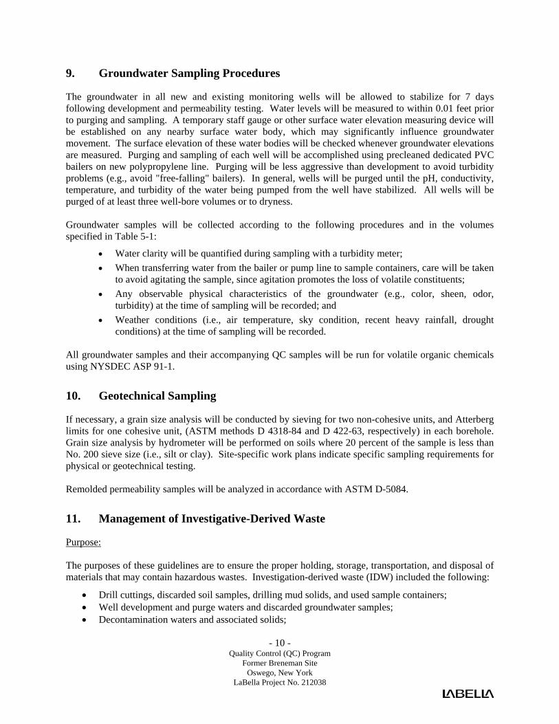
- 10 - Quality Control (QC) Program
Former Breneman Site Oswego, New York
LaBella Project No. 212038
9. Groundwater Sampling Procedures
The groundwater in all new and existing monitoring wells will be allowed to stabilize for 7 days following development and permeability testing. Water levels will be measured to within 0.01 feet prior to purging and sampling. A temporary staff gauge or other surface water elevation measuring device will be established on any nearby surface water body, which may significantly influence groundwater movement. The surface elevation of these water bodies will be checked whenever groundwater elevations are measured. Purging and sampling of each well will be accomplished using precleaned dedicated PVC bailers on new polypropylene line. Purging will be less aggressive than development to avoid turbidity problems (e.g., avoid "free-falling" bailers). In general, wells will be purged until the pH, conductivity, temperature, and turbidity of the water being pumped from the well have stabilized. All wells will be purged of at least three well-bore volumes or to dryness. Groundwater samples will be collected according to the following procedures and in the volumes specified in Table 5-1:
• Water clarity will be quantified during sampling with a turbidity meter; • When transferring water from the bailer or pump line to sample containers, care will be taken
to avoid agitating the sample, since agitation promotes the loss of volatile constituents; • Any observable physical characteristics of the groundwater (e.g., color, sheen, odor,
turbidity) at the time of sampling will be recorded; and • Weather conditions (i.e., air temperature, sky condition, recent heavy rainfall, drought
conditions) at the time of sampling will be recorded. All groundwater samples and their accompanying QC samples will be run for volatile organic chemicals using NYSDEC ASP 91-1.
10. Geotechnical Sampling
If necessary, a grain size analysis will be conducted by sieving for two non-cohesive units, and Atterberg limits for one cohesive unit, (ASTM methods D 4318-84 and D 422-63, respectively) in each borehole. Grain size analysis by hydrometer will be performed on soils where 20 percent of the sample is less than No. 200 sieve size (i.e., silt or clay). Site-specific work plans indicate specific sampling requirements for physical or geotechnical testing. Remolded permeability samples will be analyzed in accordance with ASTM D-5084.
11. Management of Investigative-Derived Waste
Purpose: The purposes of these guidelines are to ensure the proper holding, storage, transportation, and disposal of materials that may contain hazardous wastes. Investigation-derived waste (IDW) included the following:
• Drill cuttings, discarded soil samples, drilling mud solids, and used sample containers; • Well development and purge waters and discarded groundwater samples; • Decontamination waters and associated solids;
- 11 - Quality Control (QC) Program
Former Breneman Site Oswego, New York
LaBella Project No. 212038
• Soiled disposable personal protective equipment (PPE); • Used disposable sampling equipment; • Used plastic sheeting and aluminum foil; • Other equipment or materials that either contain or have been in contact with potentially-
impacted environmental media. • Because these materials may contain regulated chemical constituents, they must be managed as a
solid waste. This management may be terminated id characterization analytical results indicate the absence of these constituents.
Procedure:
1. Contain all investigation-derived wastes in Department of Transpiration (DOT)-approved 55-gallon drums, roll-off boxes, or other containers suitable for the wastes.
2. Contain wastes from separate borings or wells in separate containers (i.e. do not combine wastes from several borings/wells in a single container, unless it is a container used specifically for transfer purposes, or unless specific permission to do so has been provided by the LaBella Project Manager. Unused samples from surface sample locations within a given area may be combined.
3. To the extent practicable, separate solids from drilling muds, decontamination waters, and similar liquids. Place solids within separate containers.
4. Transfer all waste containers to a staging area. Access to this area will be controlled. Waste containers must be transferred to the staging area as soon as practicable after the generating activity is complete.
5. Pending transfer, all containers will be covered and secured when not immediately attended,
6. Label all containers with regard to contents, origin, and date of generation. Use indelible ink for all labeling.
7. Collect samples for waste characterization purposes, use boring/well sample analytical data for characterization.
8. For wastes determined to be hazardous in character, be aware on accumulation time limitations. Coordinate the disposal of these wastes with the Owner and NYSDEC.
9. Dispose of investigation-derived wastes as follows;
• Soil, water, and other environmental media for which analysis does not detect organic constituents, and for which inorganic constituents are at levels consistent with background, may be spread on-site or otherwise treated as a non0-waste material.
• Soils, water, and other environmental media in which organic compounds are detected or metals are present above background will be disposed as industrial waste. Alternate disposition must be consistent with applicable State and Federal laws.
• Personal protective equipment, disposable bailers, and similar equipment may be disposed as municipal waste, unless waste characterization results mandate disposal as industrial wastes

- 12 - Quality Control (QC) Program
Former Breneman Site Oswego, New York
LaBella Project No. 212038
12. Decontamination
Sampling methods and equipment have been chosen to minimize decontamination requirements and to prevent the possibility of cross-contamination. Decontamination of equipment will be performed between discrete sampling locations. Equipment used to collect composite samples will not require decontamination between sub-sample collection; however decontamination of equipment will be performed between separate composite samples. All drilling equipment will be decontaminated prior to drilling, after drilling each monitoring well, and after the completion of all drilling. Special attention will be given to the drilling assembly, augers, and PVC casing and screens. Drilling decontamination will consist of:
• Steam cleaning; • Scrubbing with brushes, if soil remains on equipment; and • Steam rinse.
Split spoons and other non-disposable equipment will be decontaminated between each sampling event. The sampler will be cleaned prior to each use, by one of the following procedures:
• Initially cleaned of all foreign matter; • Sanitized with a steam cleaner;
OR
• Initially cleaned of all foreign matter; • Scrubbed with brushes in trisodium phosphate or alconox solution; • Rinsed with deionized water; • Rinsed with pesticide grade methanol; • Triple rinsed with deionized water; and • Allowed to air dry.
13. Sample Containers
The volumes and containers required for the sampling activities are included in pre-washed sample containers will be ordered directly from a firm, which prepares the containers in accordance with EPA bottle washing procedures.

- 13 - Quality Control (QC) Program
Former Breneman Site Oswego, New York
LaBella Project No. 212038
Table 1 Water Samples
Type of Analysis
Type and Size of Container
Number of Containers and Sample Volume
(per sample)
Preservation
Maximum Holding
Time
Volatile Organics
40-ml glass vial with Teflon-backed septum
Two (2); fill completely, no air space
Cool to 4° C (ice in cooler), Hydrochloric acid to pH <2
7 days
Semivolatile Organics Pesticides PCBs Metals
1,000-ml amber glass jar 1,000-ml amber glass jar 1,000-ml amber glass jar 500-ml polyethylene
One (1); fill completely One (1); fill completely One (1); fill completely One (1); fill completely
Cool to 4° C (ice in cooler) Cool to 4° C (ice in cooler) Cool to 4° C (ice in cooler) Cool to 4° C (Nitric acid to pH <2
7/40 days
7/40 days
7/40 days
6 months
*
Holding time is based on verified time of sample receipt at laboratory. Note: All sample bottles will be prepared in accordance with USEPA bottle washing procedures. These
procedures are incorporated in LaBella Associates Quality Control Procedures Manual, January, 1992
TABLE 2 Soil Samples
Type of Analysis
Type and Size of
Container
Number of Containers and Sample Volume
(per sample)
Preservation
Maximum
Holding Time
Volatile Organics, Semivolatile Organics, PCBs, and Pesticides
8-oz, glass jar with Teflon-lined cap
Two (2), fill as completely as possible
Cool to 4° C (ice in cooler)
7 days
RCRA Characterization
8-oz. glass jar with Teflon-lined cap
One (1); fill completely
Cool to 4° C (ice in cooler)
Must be extracted within 10 days; analyzed with 30 days
* Holding time is based on the times from verified time of sample receipt at the laboratory.
Note: All sample bottles will be prepared in accordance with USEPA bottle washing procedures. These
procedures are incorporated in LaBella Associates Quality Control Procedures Manual, January, 1992.

- 14 - Quality Control (QC) Program
Former Breneman Site Oswego, New York
LaBella Project No. 212038
TABLE 3
List of Major Instruments for Sampling and Analysis
• MSA 360 02 /Explosimeter • S.E. International Radiation Monitor Model 4C • Photovac Micro Tip FID or PID • Organic Vapor Analyzer Foxboro (128) • Hollige Series 963 Nephlometer (turbidity meter) • EM-31 Geomics Electromagnetic Induction Device • pH/Temperature/Conductivity Meter - Portable • Hewlett Packard (HP) 1000 computer with RTE-6 operating system; and HP 9144 computer with RTE-4 operating system
equipped with Aquarius software for control and data acquisition from gas chromatograph/mass spectrometer (GC/MS) systems; combined wiley and National Bureau of Standards (NBS) mass spectral library; and data archiving on magnetic tape
• Viriam 6000 and 37000 gas chromatrographs equipped with flame ionization, electron capture, photoionization and wall detectors
as appropriate for various analyses,, and interfaced to Variam DS604 or D5634 data systems for processing data. • Spectra-Physics Model SP 4100 and SP 4270 and Variam 4270 cam puting integrators • Perkin Eimer (PE) 3000% and 3030% fully Automated Atomic Absorption Spectrophotometers (AAS) with Furnace Atomizer
and background correction system • PE Plasma II Inductively Coupled Argon Plasma (ICAP) Spectre meter with PE7500 laboratory computer • Dionex 20001 ion chromatograph with conductivity detector for anion analysis, with integrating recorder
14. Sample Custody
This section describes standard operating procedures for sample identification and chain-of-custody to be utilized for all Phase II field activities. The purpose of these procedures is to ensure that the quality of the samples is maintained during their collection, transportation, and storage through analysis. All chain-of-custody requirements comply with standard operating procedures indicated in EPA sample handling protocol. Sample identification documents must be carefully prepared so that sample identification and chain-of-custody can be maintained and sample disposition controlled. Sample identification documents include:
• Field notebooks, • Sample label, • Custody seals, and • Chain-of-custody records.

- 15 - Quality Control (QC) Program
Former Breneman Site Oswego, New York
LaBella Project No. 212038
15. Chain-of-Custody
The primary objective of the chain-of-custody procedures is to provide an accurate written or computerized record that can be used to trace the possession and handling of a sample from collection to completion of all required analyses. A sample is in custody if it is:
• In someone's physical possession; • In someone's view; • Locked up; or • Kept in a secured area that is restricted to authorized personnel.
15.1. Field Custody Procedures
• As few persons as possible should handle samples.
• Sample bottles will be obtained precleaned from a source such as I-Chem. Coolers or boxes containing cleaned bottles should be sealed with a custody tape seal during transport to the field or while in storage prior to use.
• The sample collector is personally responsible for the care and custody of samples collected until they are transferred to another person or dispatched properly under chain-of-custody rules.
• The sample collector will record sample data in the notebook.
• The site manager will determine whether proper custody procedures were followed during the fieldwork and decide if additional samples are required.
15.2. Sample Tags Sample tags attached to or affixed around the sample container must be used to properly identify all samples collected in the field. The sample tags are to be placed on the bottles so as not to obscure any QC lot numbers on the bottles; sample information must be printed in a legible manner using waterproof ink. Field identification must be sufficient to enable cross-reference with the logbook. For chain-of-custody purposes, all QC samples are subject to exactly the same custodial procedures and documentation as "real" samples. 15.3. Transfer of Custody and Shipment
• The coolers in which the samples are packed must be accompanied by a chain-of-custody record. When transferring samples, the individuals relinquishing and receiving them must sign, date, and note the time on the chain-of-custody record. This record documents sample custody transfer
• Shipping containers must be sealed with custody seals for shipment to the laboratory. The method of shipment, name of courier, and other pertinent information are entered in the "Remarks" section of the chain-of-custody record and traffic reports.
• All shipments must be accompanied by the chain-of-custody record identifying their contents. The original record accompanies the shipment. The other copies are distributed appropriately to the site manage.

- 16 - Quality Control (QC) Program
Former Breneman Site Oswego, New York
LaBella Project No. 212038
• If sent by mail, the package is registered with return receipt requested. If sent by common carrier, a bill of lading is used. Freight bills, Postal Service receipts, and bill of lading are retained as part of the permanent documentation.
15.4. Chain-of-Custody Record The chain-of-custody record must be fully completed in duplicate, using black carbon paper where possible, by the field technician who has been designated by the project manager as responsible for sample shipment to the appropriate laboratory for analysis. In addition, if samples are known to require rapid turnaround in the laboratory because of project time constraints or analytical concerns (e.g., extraction time or sample retention period limitations, etc.), the person completing the chain-of-custody record should note these constraints in the "Remarks" section of the record. 15.5. Laboratory Custody Procedures A designated sample custodian accepts custody of the shipped samples and verifies that the sample identification number matches that on the chain-of-custody record and traffic reports, if required. Pertinent information as to shipment, pickup, and courier is entered in the "Remarks" section. 15.6. Custody Seals Custody seals are preprinted adhesive-backed seals with security slots designed to break if the seals are disturbed. Sample shipping containers (coolers, cardboard boxes, etc., as appropriate) are sealed in as many places as necessary to ensure security. Seals must be signed and dated before use. On receipt at the laboratory, the custodian must check (and certify, by completing the package receipt log and LABMIS entries) that seals on boxes and bottles are intact. Strapping tape should be placed over the seals to ensure that seals are not accidentally broken during shipment.
16. Documentation
16.1. Sample Identification All containers of samples collected from the project will be identified using the following format on a label or tag fixed to the sample container (labels are to be covered with Mylar tape):
XX-YY-O/D
• XX This set of initials indicates the specific Phase II sampling project • YY These initials identify the sample location. Actual sample locations will be
recorded in the task log. • O/D An "O" designates an original sample; "D" identifies it as a duplicate.
Each sample will be labeled, chemically preserved, if required and sealed immediately after collection. To minimize handling of sample containers, labels will be filled out prior to sample collection. The sample label will be filled out using waterproof ink and will be firmly affixed to the sample containers and protected with Mylar tape. The sample label will give the following information:
• Name of sampler,

- 17 - Quality Control (QC) Program
Former Breneman Site Oswego, New York
LaBella Project No. 212038
• Date and time of collection, • Sample number, • Analysis required, • pH, and • Preservation.
16.2. Daily Logs Daily logs and data forms are necessary to provide sufficient data and observations to enable participants to reconstruct event that occurred during the project and to refresh the memory of the field personnel if called upon to give testimony during legal proceedings. All daily logs will be kept in a bound waterproof notebook containing numbered pages. All entries will be made in waterproof ink, dated, and signed. No pages will be removed for any reason. Corrections will be made according to the procedures given at the end of this section. The daily logs will include a site log and task log. The site log is the responsibility of the site manager and will include a complete summary of the day's activity at the site. The Task Log will include:
• Name of person making entry (signature). • Names of team members on-site. • Levels of personnel protection:
− Level of protection originally used; − Changes in protection, if required; and − Reasons for changes.
• Time spent collecting samples. • Documentation on samples taken, including:
− Sampling location and depth station numbers; − Sampling date and time, sampling personnel; − Type of sample (grab, composite, etc.); and − Sample matrix.
• On-site measurement data. • Field observations and remarks. • Weather conditions, wind direction, etc. • Unusual circumstances or difficulties. • Initials of person recording the information.

- 18 - Quality Control (QC) Program
Former Breneman Site Oswego, New York
LaBella Project No. 212038
17. Corrections to Documentation
17.1. Notebook As with any data logbooks, no pages will be removed for any reason. If corrections are necessary, these must be made by drawing a single line through the original entry (so that the original entry can still be read) and writing the corrected entry alongside. The correction must be initialed and dated. Most corrected errors will require a footnote explaining the correction. 17.2. Sampling Forms As previously stated, all sample identification tags, chain-of-custody records, and other forms must be written in waterproof ink. None of these documents are to be destroyed or thrown away, even if they are illegible or contain inaccuracies that require a replacement document. If an error is made on a document assigned to one individual, that individual may make corrections simply by crossing a line through the error and entering the corrected information. The incorrect information should not be obliterated. Any subsequent error discovered on a document should be corrected by the person who made the entry. All corrections must be initialed and dated. 17.3. Photographs Photographs will be taken as directed by the site manager. Documentation of a photograph is crucial to its validity as a representation of an existing situation. The following information will be noted in the task log concerning photographs:
• Date, time, location photograph was taken; • Photographer (signature); • Weather conditions; • Description of photograph taken; • Reasons why photograph was taken; • Sequential number of the photograph and the film roll number; and • Camera lens system used.
After the photographs have been developed, the information recorded in the field notebook should be transferred to the back of the photographs
18. Sample Handling, Packaging, and Shipping
The transportation and handling of samples must be accomplished in a manner that not only protects the integrity of the sample, but also prevents any detrimental effects due to the possible hazardous nature of samples. Regulations for packaging, marking, labeling, and shipping hazardous materials are promulgated by the United States Department of Transportation (DOT) in the Code of Federal Regulation, 49 CFR 171 through 177. All samples will be delivered to the laboratory with 24 to 48 hours from the day of collection. All chain-of-custody requirements must comply with standard operating procedures in the EPA sample handling protocol. All sample control and chain-of-custody procedures applicable to the Consultant are presented in the Field Personnel Chain-of-Custody Documentation and Quality Control Procedures

- 19 - Quality Control (QC) Program
Former Breneman Site Oswego, New York
LaBella Project No. 212038
Manual, January 1992. 18.1. Sample Packaging Samples must be packaged carefully to avoid breakage or contamination and must be shipped to the laboratory at proper temperatures. The following sample packaging requirements will be followed:
• Sample bottle lids must never be mixed. All sample lids must stay with the original containers.
• The sample volume level can be marked by placing the top of the label at the appropriate sample height, or with a grease pencil. This procedure will help the laboratory to determine if any leakage occurred during shipment. The label should not cover any bottle preparation QC lot numbers.
• All sample bottles are placed in a plastic bag to minimize the potential for vermiculite contamination.
• Shipping coolers must be partially filled with packing materials and ice when required, to prevent the bottles from moving during shipment.
• The sample bottles must be placed in the cooler in such a way as to ensure that they do not touch one another.
• The environmental samples are to be cooled. The use of "blue ice" or some other artificial icing material is preferred. If necessary, ice may be used, provided that it is placed in plastic bags. Ice is not to be used as a substitute for packing materials.
• Any remaining space in the cooler should be filled with inert packing material. Under no circumstances should material such as sawdust, sand, etc., be used.
• A duplicate custody record and traffic reports, if required must be placed in a plastic bag and taped to the bottom of the cooler lid. Custody seals are affixed to the sample cooler.
18.2. Shipping Containers Shipping containers are to be custody-sealed for shipment as appropriate. The container custody seal will consist of filament tape wrapped around the package at least twice and custody seals affixed in such a way that access to the container can be gained only by cutting the filament tape and breaking a seal. Field personnel will make arrangements for transportation of samples to the lab. When custody is relinquished to a shipper, field personnel will telephone the lab custodian to inform him of the expected time of arrival of the sample shipment and to advise him of any time constraints on sample analysis. The lab must be notified as early in the week as possible, and in no case later than 3 p.m. (EST) on Thursday, regarding samples intended for Saturday delivery.

- 20 - Quality Control (QC) Program
Former Breneman Site Oswego, New York
LaBella Project No. 212038
18.3. Marking and Labeling • Use abbreviations only where specified.
• The words "This End Up" or "This Side Up" must be clearly printed on the top of the outer package. Upward pointing arrows should be placed on the sides of the package. The words "Laboratory Samples" should also be printed on the top of the package.
• After a sample container has been sealed, two chain-of-custody seals are placed on the container, one on the front and one on the back. The seals are protected from accidental damage by placing strapping tape over then.
• If samples are designated as medium or high hazard, they must be sealed in metal paint cans, placed in the cooler with vermiculite and labeled and placarded in accordance with DOT regulations.
• In addition, the coolers must also be labeled and placarded in accordance with DOT regulations if shipping medium and high hazard samples.
19. Calibration Procedures and Frequency
All instruments and equipment used during sampling and analysis will be operated, calibrated, and maintained according to the manufacturer's guidelines and recommendations as well as criteria set forth in the applicable analytical methodology references. Operation, calibration, and maintenance will be performed by personnel properly trained in these procedures. Documentation of all routine and special maintenance and calibration information will be maintained in an appropriate logbook or reference file, and will be available on request. Table 7-1 lists the major instruments to be used for sampling and analysis. Brief descriptions of calibration procedures for major field and laboratory instruments follow.
20. Field Instrumentation
20.1. Photovac Micro Tip Flameionizer (FID) Standard operating procedures for the FID require that routine maintenance and calibration be performed every six months. Field calibration will be performed on a daily basis. The packages used for calibration are non-toxic analyzed gas mixtures available in pressurized containers. 20.2. Photovac/MiniRea Photoionization Detector (PID) Standard operating procedures for the PID require that routine maintenance and calibration be performed every six months. Field calibration will be performed on a daily basis. The packages used for calibration are non-toxic analyzed gas mixtures available in pressurized containers. 20.3. Organic Vapor Analyzer Organic vapor analyzers (OVAs) are calibrated and routine maintenance performed every six months when the units are not in use. Calibration is performed and the major system checks are performed prior to the instrument being released for field use. Calibration of the OVA 128 GC must be performed by a factory-authorized service representative. The

- 21 - Quality Control (QC) Program
Former Breneman Site Oswego, New York
LaBella Project No. 212038
instrument is removed from its protective case and the probe is connected to the base unit. After checking for an airtight seal in the sample line (plugging the sample inlet to stop the pump), the hydrogen supply is turned on and the pressure is set to 10 psi. The electronics are turned on and the instrument is allowed to warm up for at least 5 minutes. After warm up, the instrument is zeroed on the "X10" scale using the adjust knob. The flame is then lit and a gas-tight sample bag is filled with a mixture of 100 ppm methane in air. The sample bag is then attached to the probe inlet and the internal pump is allowed to draw in as much sample as is needed. R32 on the control board is adjusted to read 100 ppm on the "X10" scale and then the hydrogen supply is shut down. The pump can now be turned off and the sample bag removed. Using the adjust knob, the meter is set to read 4 ppm on the "X1" scale. Switching back to the "X10" scale the adjust knob is again used to set the meter to 40 ppm. The scale is then set to "X100" and R33 is adjusted until the meter reads 40 ppm on the "X100" scale. The OVA has a detection limit of 0.1 ppm in methane equivalents and a working range of 0 to 1,000 ppm. During daily field use, system checks are performed which involve calibration and maintenance of the pump systems, gases, and filters. Care is taken to check for and prevent clogging or leaks. Quad rings and the burner chamber are examined on a weekly basis. Routine biannual maintenance includes a thorough cleaning as well as a re-examination of the pump system for leaks and wear. Parts are replaced as necessary. Instrument operation is verified by calibrating and running the OVA for 4 to 6 hours. An instrument specific logbook is maintained with the OVA to document its use and maintenance. 20.4. Conductance, Temperature, and pH Tester Temperature and conductance instruments are factory calibrated. Temperature accuracy can be checked against an NBS certified thermometer prior to field use if necessary. Conductance accuracy may be checked with a solution of known conductance and recalibration can be instituted, if necessary. To recalibrate conductance, remove the black plug revealing the adjustment potentiometer screw. Add standard solution to cup, discard and refill. Repeat procedure until the digital display indicates the same value twice in a row. Adjust the potentiometer until the digital display indicates the known value of conductance. To increase the digital display reading, turn the adjustment potentiometer screw counter-clockwise (clockwise to decrease). To standardize the pH electrode and meter, place the pH electrode in the 7.0 buffer bottle. Adjust the "ZERO" potentiometer on the face of the tester so that the digital display indicates 7.00. Then place the pH electrode in the 4.0 or 10.0 buffer bottle (depending on where you expect the actual measurement to be). Adjust the "SLOPE" potentiometer on the face of the tester so that the digital display indicates the value of the buffer chosen. Note: There is interaction between the "ZERO" and "SLOPE" adjustments, so the procedure should be
repeated several times. Do not subject the pH electrode to freezing temperatures. It is good practice to rinse the electrode in distilled water when going from one buffer to another. When not in use the cap should be kept on the electrode. Keeping the cotton in the cap moist will keep the electrode ready to use. Moisten the cotton frequently (once a week, usually).

- 22 - Quality Control (QC) Program
Former Breneman Site Oswego, New York
LaBella Project No. 212038
20.5. 02/Explosimeter The primary maintenance item of the Model 260 is the rechargeable 2.4 volt (V) nickel cadmium battery. The battery is recharged by removing the screw cap covering receptacle and connecting one end of the charging cable to the instrument and the other end to a 115V AC outlet. The battery can also be recharged using a 12V DC source. An accessory battery charging cable is available, one end of which plugs into the Model 260 while the other end is fitted with an automobile cigarette lighter plug. Recommended charging time is 16 hours. Before the calibration of the combustible gas indicator can be checked, the Model 260 must be in operating condition. Calibration check-adjustment is made as follows:
1. Attach the flow control to the recommended calibration gas tank.
2. Connect the adapter-hose to the flow control.
3. Open flow control valve.
4. Connect the adapter-hose fitting to the inlet of the instrument; after about 15 seconds the LEL meter pointer should be stable and within the range specified on the calibration sheet accompanying the calibration equipment. If the meter pointer is not in the correct range, stop the flow; remove the right hand side cover. Turn on the flow and adjust the "S" control with a small screwdriver to obtain a reading as specified on the calibration sheet.
5. Disconnect the adapter-hose fitting from the instrument.
6. Close the flow control valve.
7. Remove the adapter-hose from the flow control.
8. Remove the flow control from the calibration gas tank.
9. Replace the side cover on the Model 260. CAUTION: Calibration gas tank contents are under pressure. Use no oil, grease, or flammable solvents on the flow control or the calibration gas tank. Do not store calibration gas tank near heat or fire or in rooms used for habitation. Do not throw in fire, incinerate, or puncture. Keep out of reach of children. It is illegal and hazardous to refill this tank. Do not attach the calibration gas tank to any other apparatus than described above. Do not attach any gas tank other than MSA calibration tanks to the regulator. 20.6. Nephelometer (Turbidity Meter) The Series 95 nephelometer is calibrated before each use. Allow the instrument to warm up for approximately 2 hours. Using turbidity-free deionized water, zero the meter. Set the scale to 100, fill with a 40 NTU standard (AEPA-1 turbidity standard from Advanced Polymer Systems, Inc.), and insert into the instrument. Adjust the standardize control to give a readout of 200. Re-zero the instrument and repeat these steps with the scale set at 10 and 1 using 4.0 and 0.4 NTU standards, respectively. These standards are prepared by diluting aliquots of the 40 NTU standard.

- 23 - Quality Control (QC) Program
Former Breneman Site Oswego, New York
LaBella Project No. 212038
20.7. S.E. International Radiation Monitor Model 4EC This radiation monitor detects alpha, beta, gamma, and X-rays. The analog meter is scaled in CPM (counts per minute) or mR/hr (milli-Roentgens per hour), and the X1, X10, X100 switch extends the effective measurement range. This handheld unit is powered by a single 9-volt battery that offers up to 2,000 hours of operation.
21. Internal Quality Control Checks
QC data are necessary to determine precision and accuracy and to demonstrate the absence of interferences and/or contamination of field equipment. Field-based QC will comprise at least 10% of each data set generated and will consist of standards, replicates, spikes, and blanks. Field duplicates and field blanks will be analyzed by the laboratory as samples and will not necessarily be identified to the laboratory as duplicates or blanks. For each matrix, field duplicates will be provided at a rate of one per 10 samples collected or one per shipment, whichever is greater. Field blanks which consist of trip, routine field, and rinsate blanks will be provided at a rate of one per 20 samples collected for each parameter group, or one per shipment, whichever is greater. Calculations will be performed for recoveries and standard deviations along with review of retention times, response factors, chromatograms, calibration, tuning, and all other QC information generated. All QC data, including split samples, will be documented in the site logbook. QC records will be retained and results reported with sample data. 21.1. Blank Samples Blank samples are analyzed in order to assess possible contamination from the field and/or laboratory so that corrective measures may be taken, if necessary. Field samples are discussed in the following subsection: 21.2. Field Blanks Various types of blanks are used to check the cleanliness of field handling methods. The following types of blanks may be used: the trip blank, the routine field blank, and the field equipment blank. They are analyzed in the laboratory as samples, and their purpose is to assess the sampling and transport procedures as possible sources of sample contamination. Field staff may add blanks if field circumstances are such that they consider normal procedures are not sufficient to prevent or control sample contamination, or at the direction of the project manager. Rigorous documentation of all blanks in the site logbooks is mandatory.
• Routine Field Blanks or bottle blanks are blank samples prepared in the field to access
ambient field conditions. They will be prepared by filling empty sample containers with deionized water and any necessary preservatives. They will be handled like a sample and shipped to the laboratory for analysis.
• Trip Blanks are similar to routine field blanks with the exception that they are not exposed
to field conditions. Their analytical results give the overall level of contamination from everything except ambient field conditions. For the RI/FS, one trip blank will be collected with every batch of water samples for volatile organic analysis. Each trip blank will be prepared by filling a 40-ml vial with deionized water prior to the sampling trip, transported to the site, handled like a sample, and returned to the laboratory for analysis without being

- 24 - Quality Control (QC) Program
Former Breneman Site Oswego, New York
LaBella Project No. 212038
opened in the field. • Field Equipment Blanks are blank samples (sometimes called transfer blanks or rinsate
blanks) designed to demonstrate that sampling equipment has been properly prepared and cleaned before field use, and that cleaning procedures between samples are sufficient to minimize cross contamination. If a sampling team is familiar with a particular site, they may be able to predict which areas or samples are likely to have the highest concentration of contaminants. Unless other constraints apply, these samples should be taken last to avoid excessive contamination of sampling equipment.
21.3. Field Duplicates Field duplicate samples consist of a set of two samples collected independently at a sampling location during a single sampling event. In some instances the field duplicate can be a blind duplicate, i.e., indistinguishable from other analytical samples so that personnel performing the analyses are not able to determine which samples are field duplicates. Field duplicates are designed to assess the consistency of the overall sampling and analytical system. 21.4. Quality Control Check Samples Inorganic and organic control check samples are available from EPA free of charge and are used as a means of evaluating analytical techniques of the analyst. Control check samples are subjected to the entire sample procedure, including extraction, digestion, etc., as appropriate for the analytical method utilized. I:\BROADWELL\212038\RIWP\QCP.DOC

LaBella Associates, P.C. 300 State Street Rochester, New York 14614
Appendix 4 Health and Safety Plan
Site Health and Safety Plan L ocation:
Former Breneman Site 8 East Utica Street Oswego, New York 13126 P repared For:
Canalview Development, LLC 70 East First Street Oswego, New York 13126 LaBella Project No. 212038 May 2013

Site Health and Safety Plan
Location: Former Breneman Site
8 East Utica Street Oswego, New York 13126
Prepared For: Canalview Development, LLC
70 East First Street Oswego, New York 13126
LaBella Project No. 212038
May 2013
LaBella Associates, P.C. 300 State Street Rochester, New York 14614

Table of Contents
Page SITE HEALTH AND SAFETY PLAN ................................................................................................. i EMERGENCY CONTACTS ................................................................................................................ ii MAP AND DIRECTIONS TO THE MEDICAL FACILITY ............................................................. iii 1.0 Introduction .............................................................................................................................. 1 2.0 Responsibilities ........................................................................................................................ 1 3.0 Activities Covered ................................................................................................................... 1 4.0 Work Area Access and Site Control ........................................................................................ 1 5.0 Potential Health and Safety Hazards ........................................................................................ 1 5.1 Hazards Due to Heavy Machinery .............................................................................. 2 5.2 Excavation Hazards .................................................................................................... 2 5.3 Cuts, Punctures and Other Injuries ............................................................................. 2 5.4 Injury Due to Exposure of Chemical Hazards ............................................................ 3 5.5 Injuries Due to Extreme Hot or Cold Weather Conditions ......................................... 3 5.6 Potential Exposure to Asbestos ................................................................................... 3 5.7 Potential Exposure to 232Thorium ............................................................................... 4 6.0 Work Zones .............................................................................................................................. 4 7.0 Decontamination Procedures ................................................................................................... 4 8.0 Personal Protective Equipment ................................................................................................ 5 9.0 Air Monitoring ......................................................................................................................... 5 10.0 Emergency Action Plan ........................................................................................................... 5 11.0 Medical Surveillance ............................................................................................................... 6 12.0 Employee Training................................................................................................................... 6

- i - May 2013
SITE HEALTH AND SAFETY PLAN
Project Title: Former Breneman Site - Brownfield Cleanup Program Project Number: 212038 Project Location (Site): 8 East Utica Street, Oswego, New York
Environmental Director: Gregory Senecal, CHMM Project Manager: Dave Engert, CHMM Plan Review Date: Plan Approval Date: Plan Approved By: Mr. Richard Rote, CIH Site Safety Supervisor: Jennifer Gillen Site Contact: To Be Determined Safety Director: Rick Rote, CIH Proposed Date(s) of Field Activities:
To Be Determined
Site Conditions: Sloping west, encompassing approximately 2.1044 acres Site Environmental Information Provided By:
• Site Prioritization Report, Weston Solutions Inc., 2005 • Breneman Site Development Projects, Phase I Report,
Nussbaumer and Clarke, Inc., 1996 • Final Draft Site Inspection Report, Halliburton NUS
Environmental Corporation, 1991 • Preliminary Environmental Assessment of the Former Breneman
Building O’Brien and Gere Engineers, Inc. 1991 • Final Site Remediation Report Brenneman Building,
Environmental Products and Services, Inc.1990
Air Monitoring Provided By: LaBella Associates, P.C. Site Control Provided By: Contractor(s)

- ii - May 2013
EMERGENCY CONTACTS
Name Phone Number Ambulance: As Per Emergency Service 911 Hospital Emergency: Oswego Hospital 315-349-5511 Poison Control Center: Upstate Medical University 1-800-222-1222 Police (local, state): Oswego County Sheriff 911 Fire Department: Oswego Fire Department 911 Site Contact: Shane Broadwell 315-343-1600 Agency Contact: NYSDEC – Joshua Cook, P.E. 315-426-7400 NYSDOH – Richard Jones 315-477-8148 Poison Control Center 1-800-222-1222 Environmental Director: Greg Senecal, CHMM Direct: 585-295-6243 Cell: 585-752-6480 Home: 585-323-2142 Project Manager: Dave Engert, CHMM. Direct: 585-295-630 Cell: 585-737-3293 Site Safety Supervisor: Jennifer Gillen Direct: 585-295-6648 Cell: 315-402-6480 Safety Director Rick Rote, CIH Direct: 585-295-6241

MAP AND DIRECTIONS TO THE MEDICAL FACILITY - OSWEGO HOSPITAL
Total Time: 4 minutes
Total Distance: 0.7 miles Start: 8 East Utica Street, Oswego, NY 13126
1: Start out going West on East Utica Street 0.5 mi
2: Turn RIGHT onto West Fifth Street. 0.2 mi
3: End at 110 West Sixth Street Oswego, NY 13126
- iii - May 2013

1 May 2013
1.0 Introduction The purpose of this Health and Safety Plan (HASP) it to provide guidelines for responding to potential health and safety issues that may be encountered during the Remedial Investigation (RI) at the Site located at the Former Breneman Site, 8 East Utica Street in the City of Oswego, Oswego County, New York. This HASP only reflects the policies of LaBella Associates P.C. The requirements of this HASP are applicable to all approved LaBella personnel at the work site. This document’s project specifications and the Community Air Monitoring Plan (CAMP) are to be consulted for guidance in preventing and quickly abating any threat to human safety or the environment. The provisions of the HASP were developed in general accordance with 29 CFR 1910 and 29 CFR 1926 and do not replace or supersede any regulatory requirements of the USEPA, NYSDEC, OSHA or and other regulatory body. 2.0 Responsibilities This HASP presents guidelines to minimize the risk of injury to project personnel, and to provide rapid response in the event of injury. The HASP is applicable only to activities of approved LaBella personnel and their authorized visitors. The Project Manager shall implement the provisions of this HASP for the duration of the project. It is the responsibility of LaBella employees to follow the requirements of this HASP, and all applicable company safety procedures. 3.0 Activities Covered The activities covered under this HASP are limited to the following:
Management of environmental investigation and remediation activities Environmental Monitoring Collection of samples Management of excavated soil and fill.
4.0 Work Area Access and Site Control The contractor(s) will have primary responsibility for work area access and site control. However, a minimum requirement for work area designation and control will consist of:
• Drilling (Geoprobe®/Rotary) – Orange cones to establish at least a 10-foot by 10-foot work area • Test Pitting – Orange cones and orange temporary fencing to establish at least 10-feet of distance
between test pit and fencing. 5.0 Potential Health and Safety Hazards This section lists some potential health and safety hazards that project personnel may encounter at the project site and some actions to be implemented by approved personnel to control and reduce the associated risk to health and safety. This is not intended to be a complete listing of any and all potential health and safety hazards. New or different hazards may be encountered as site environmental and site work conditions change. The suggested actions to be taken under this plan are not to be substituted for good judgment on the part of project personnel. At all times, the Site Safety Officer has responsibility for site safety and his or her instructions must be followed.

2 May 2013
5.1 Hazards Due to Heavy Machinery
Potential Hazard: Heavy machinery including trucks, excavators, backhoes, etc will be in operation at the site. The presence of such equipment presents the danger of being struck or crushed. Use caution when working near heavy machinery.
Protective Action:
Make sure that operators are aware of your activities, and heed operator’s instructions and warnings. Wear bright colored clothing and walk safe distances from heavy equipment. A hard hat, safety glasses and steel toe shoes are required.
5.2 Excavation Hazards Potential Hazard:
Excavations and trenches can collapse, causing injury or death. Edges of excavations can be unstable and collapse. Toxic and asphyxiant gases can accumulate in confined spaces and trenches. Excavations that require working within the excavation will require air monitoring in the breathing zone (refer to Section 9.0). Excavations left open create a fall hazard which can cause injury or death. Protective Action: Personnel must receive approval from the Project Manager to enter an excavation for any reason. Subsequently, approved personnel are to receive authorization for entry from the Site Safety Officer. Approved personnel are not to enter excavations over 4 feet in depth unless excavations are adequately sloped. Additional personal protective equipment may be required based on the air monitoring.
Personnel should exercise caution near all excavations at the site as it is expected that excavation sidewalls will be unstable. All excavations will be backfilled by the end of each day. Additionally, no test pit will be left unattended during the day. Fencing and/or barriers accompanied by “no trespassing” signs should be placed around all excavations when left open for any period of time when work is not being conducted.
5.3 Cuts, Punctures and Other Injuries
Potential Hazard: In any excavation or construction, work site there is the potential for the presence of sharp or
jagged edges on rock, metal materials, and other sharp objects. Serious cuts and punctures can result in loss of blood and infection.
Protective Action: The Project Manager is responsible for making First Aid supplies available at the work site to treat minor injuries. The Site Safety Officer is responsible for arranging the transportation of authorized on-site personnel to medical facilities when First Aid treatment in not sufficient. Do not move seriously injured workers. All injuries requiring treatment are to be reported to the Project Manager. Serious injuries are to be reported immediately to the Site Safety Officer

3 May 2013
5.4 Injury Due to Exposure of Chemical Hazards Potential Hazards:
Volatile organic vapors from petroleum products, chlorinated solvents or other chemicals may be encountered during excavation activities at the project work site. Inhalation of high concentrations of organic vapors can cause headache, stupor, drowsiness, confusion and other health effects. Skin contact can cause irritation, chemical burn, or dermatitis.
Protective Action:
The presence of organic vapors may be detected by their odor and by monitoring instrumentation. Approved employees will not work in environments where hazardous concentrations of organic vapors are present. Air monitoring (refer to Section 9.0 and to the Modified CAMP in Appendix 7) of the work area will be performed at least every 60 minutes or more often using a Photoionization Detector (PID). Personnel are to leave the work area whenever PID measurements of ambient air exceed 25 ppm consistently for a 5 minute period. In the event that sustained total volatile organic compound (VOC) readings of 25 ppm is encountered personnel should upgrade personal protective equipment to Level C (refer to Section 8.0) and an Exclusion Zone should be established around the work area to limit and monitor access to this area (refer to Section 6.0).
5.5 Injuries Due to Extreme Hot or Cold Weather Conditions
Potential Hazards: Extreme hot weather conditions can cause heat exhaustion, heat stress and heat stroke or extreme cold weather conditions can cause hypothermia.
Protective Action:
Precaution measures should be taken such as dress appropriately for the weather conditions and drink plenty of fluid. If personnel should suffer from any of the above conditions, proper techniques should be taken to cool down or heat up the body and taken to the nearest hospital if needed.
5.6 Potential Exposure to Asbestos
Potential Hazards: During ground intrusive activities (e.g., test pitting or drilling) soil containing asbestos may be encountered. Asbestos is friable when dry and can be inhaled when exposed to air.
Protective Action:
The presence of asbestos can be identified through visual observation of a white magnesium silicate material. If encountered, work should be halted and a sample of the suspected asbestos should be collected and placed in a plastic sealable bag. This sample should be sent to the asbestos laboratory at LaBella Associates for analysis.

4 May 2013
5.7 Potential Exposure to Thorium232
Potential Hazards: During ground intrusive activities (e.g., test pitting or drilling) soil containing 232Thorium may be encountered. 232Thorium is a radioactive substance and poses an exposure risk to humans once encountered.
Protective Action:
Each test pit, soil sample, or other soil from the subsurface should initially be screened with the Ludlum meter to check the level of radiation on the soil as compared to the Site background level of radiation. Should the level of radiation on the soil sample exceed 2 times the Site background level, then work should be halted at the specified location and Mr. Rick Rote of LaBella Associates, P.C. should be contacted immediately (see page ii Emergency Contacts).
6.0 Work Zones In the event that conditions warrant establishing various work zones (i.e., based on hazards - Section 5.4), the following work zones should be established: Exclusion Zone (EZ):
The EZ will be established in the immediate vicinity and adjacent downwind direction of site activities that elevate breathing zone VOC concentrations to unacceptable levels based on field screening. These site activities include contaminated soil excavation and soil sampling activities. If access to the site is required to accommodate non-project related personnel then an EZ will be established by constructing a barrier around the work area (yellow caution tape and/or construction fencing). The EZ barrier shall encompass the work area and any equipment staging/soil staging areas necessary to perform the associated work. The contractor(s) will be responsible for establishing the EZ and limiting access to approved personnel. Depending on the condition for establishing the EZ, access to the EZ may require adequate PPE (e.g., Level C). Contaminant Reduction Zone (CRZ): The CRZ will be the area where personnel entering the EZ will don proper PPE prior to entering the EZ and the area where PPE may be removed. The CRZ will also be the area where decontamination of equipment and personnel will be conducted as necessary.
7.0 Decontamination Procedures Upon leaving the work area, approved personnel shall decontaminate footwear as needed. Under normal work conditions, detailed personal decontamination procedures will not be necessary. Work clothing may become contaminated in the event of an unexpected splash or spill or contact with a contaminated substance. Minor splashes on clothing and footwear can be rinsed with clean water. Heavily contaminated clothing should be removed if it cannot be rinsed with water. Personnel assigned to this project should be prepared with a change of clothing whenever on site. Personnel will use the contractor’s disposal container for disposal of PPE.

5 May 2013
8.0 Personal Protective Equipment Generally, site conditions at this work site require level of protection of Level D or modified Level D. However, air monitoring will be conducted to determine if up-grading to Level C PPE is required (refer to Section 9.0). Descriptions of the typical safety equipment associated with Level D and Level C are provided below:
Level D: Hard hat, safety glasses, rubber nitrile sampling gloves, steel toe construction grade boots, etc. Level C: Level D PPE and full or ½-face respirator and tyvek suit (if necessary). [Note: Organic vapor cartridges are to be changed after each 8-hours of use or more frequently.]
9.0 Air Monitoring According to 29 CFR 1910.120(h), air monitoring shall be used to identify and quantify airborne levels of hazardous substances and health hazards in order to determine the appropriate level of employee protection required for personnel working onsite. Air monitoring will consist at a minimum of the procedures described in Appendix 7 “Site Specific CAMP”. Please refer to the Site Specific CAMP for further details on air monitoring at the Site. The Air Monitor will utilize a photoionization Detector (PID) to screen the ambient air in the work areas for total Volatile Organic Compounds (VOCs) and a DustTrak tm Model 8520 aerosol monitor or equivalent for measuring particulates. Work area ambient air will generally be monitored in the work area and downwind of the work area. Air monitoring of the work areas and downwind of the work areas will be performed at least every 60 minutes or more often using a PID, and the DustTrak meter. If sustained PID readings of greater than 25 ppm are recorded in the breathing zone, then either personnel are to leave the work area until satisfactory readings are obtained or approved personnel may re-enter the work areas wearing at a minimum a ½ face respirator with organic vapor cartridges for an 8-hour duration (i.e., upgrade to Level C PPE). Organic vapor cartridges are to be changed after each 8-hours of use or more frequently, if necessary. If PID readings are sustained, in the work area, at levels above 25 ppm for a 5 minute average, work will be stopped immediately until safe levels of VOCs are encountered or additional PPE will be required (i.e., Level B). If dust concentrations exceed the upwind concentration by 150 µg/m3 (0.15 mg/m3) consistently for a 10 minute period within the work area or at the downwind location, then LaBella personnel may not re-enter the work area until dust concentrations in the work area decrease below 150 µg/m3 (0.15 mg/m3), which may be accomplished by the construction manager implementing dust control or suppression measures. 10.0 Emergency Action Plan In the event of an emergency, employees are to turn off and shut down all powered equipment and leave the work areas immediately. Employees are to walk or drive out of the Site as quickly as possible and wait at the assigned 'safe area'. Follow the instructions of the Site Safety Officer. Employees are not authorized or trained to provide rescue and medical efforts. Rescue and medical efforts will be provided by local authorities.
6 May 2013
11.0 Medical Surveillance Medical surveillance will be provided to all employees who are injured due to overexposure from an emergency incident involving hazardous substances at this site. 12.0 Employee Training Personnel who are not familiar with this site plan will receive training on its entire content and organization before working at the Site. Individuals involved with the remedial investigation must be 40-hour OSHA HAZWOPER trained with current 8-hour refresher certification. I:\BROADWELL\212038\RIWP\APPENDIX 4 - HASP\HASP.DOC

Table 1 Exposure Limits and Recognition Qualities
PEL-TWA (ppm)(b)(d)
TLV-TWA (ppm)(c)(d) STEL LEL (%)(e) UEL (%)(f) IDLH (ppm)(g)(d) Odor
Odor Threshold (ppm) Ionization Potential Compound
Acetone 750 500 NA 2.15 13.2 20,000 Sweet 4.58 9.69
Anthracene 0.2 0.2 NA NA NA NA Faint aromatic NA NA
Benzene 1 0.5 5 1.3 7.9 3000 Pleasant 8.65 9.24
Benzo (a) pyrene (coal tar pitch volatiles) 0.2 0.1 NA NA NA 700 NA NA NA
Benzo (a)anthracene NA NA NA NA NA NA NA NA NA
Benzo (b) Fluoranthene NA NA NA NA NA NA NA NA NA
Benzo (g,h,i)perylene NA NA NA NA NA NA NA NA NA
Benzo (k) Fluoranthene NA NA NA NA NA NA NA NA NA
Bromodichloromethane NA NA NA NA NA NA NA NA 10.88
Carbon Disulfide 20 1 NA 1.3 50 500 Odorless or strong garlic type 0.096 10.07
Chlorobenzene 75 10 NA 1.3 9.6 2,400 Faint almond 0.741 9.07
Chloroform 50 2 NA NA NA 1,000 ethereal odor 11.7 11.42
Chrysene NA NA NA NA NA NA NA NA NA
1,2-Dichloroethylene 200 200 NA 9.7 12.8 400 Acrid NA 9.65
1,2-Dichlorobenzene 50 25 NA 2.2 9.2 Pleasant 9.07
Ethylbenzene 100 100 NA 1 6.7 2,000 Ether 2.3 8.76
Fluoranthene NA NA NA NA NA NA NA NA NA
Fluorene NA NA NA NA NA NA NA NA NA
Isopropylbenzene NA NA NA NA NA NA NA NA NA
Methylene Chloride 500 50 NA 12 23 5,000 Chloroform-like 10.2 11.35
Naphthalene 10, Skin 10 NA 0.9 5.9 250 Moth Balls 0.3 8.12
n-propylbenzene NA NA NA NA NA NA NA NA NA
Phenanthrene NA NA NA NA NA NA NA NA NA
Pyrene NA NA NA NA NA NA NA NA NA
p-Isopropylbenzene NA NA NA NA NA NA NA NA NA
sec-Butylbenzene NA NA NA NA NA NA NA NA NA
Tetrachloroethane NA NA NA NA NA NA Sweet NA NA
Toluene 100 100 NA 0.9 9.5 2,000 Sweet 2.1 8.82
Trichloroethylene 100 50 NA 8 12.5 1,000 Chloroform 1.36 9.45
1,2,4-Trimethylbenzene NA 25 NA 0.9 6.4 NA Distinct 2.4 NA
1,3,5-Trimethylbenzene NA 25 NA NA NA NA Distinct 2.4 NA
Vinyl Chloride 1 1 NA NA NA NA NA NA NA
Xylenes (o,m,p) 100 100 NA 1 7 1,000 Sweet 1.1 8.56 Metals
Arsenic 0.01 0.2 NA NA NA 100, Ca Almond NA NA
Cadmium 0.2 0.5 NA NA NA NA NA NA NA
Chromium 1 0.5 NA NA NA NA NA NA NA
Lead 0.05 0.15 NA NA NA 700 NA NA NA
Mercury 0.05 0.05 NA NA NA 28 Odorless NA NA
Selenium 0.2 0.02 NA NA NA Unknown NA NA NA Other Asbestos 0.1 (f/cc) NA 1.0 (f/cc) NA NA NA NA NA NA

Table 1 Notes: (a) Skin = Skin Absorption (b) OSHA-PEL Permissible Exposure Limit (flame weighted average, 8-hour): NIOSH Guide, June 1990 (c) ACGIH – 8 hour time weighted average from Threshold Limit Values and Biological Exposure Indices for 2003. (d) Metal compounds in mg/m3 (e) Lower Exposure Limit (%) (f) Upper Exposure Limit (%) (g) Immediately Dangerous to Life or Health Level: NIOSH Guide, June 1990.
Notes: 1. All values are given in parts per million (PPM) unless otherwise indicated. 2. Ca = Possible Human Carcinogen, no IDLH information.

LaBella Associates, P.C. 300 State Street Rochester, New York 14614
Appendix 5 Anticipated Project Schedule

ID Task Name
1 BCP Agreement Executed
2 Citizen Participation Plan (CPP) Development/Submission
3 NYSDEC Review and Approval of CPP
4 Remedial Investigation Work Plan (RIWP) Development/Submission
5 30 Day NYSDEC Review Period - RIWP
6 RIWP Revisions based on NYSDEC Comments
7 15 Day NYSDEC Review and Approval - RIWP
8 30 Day Public Comment Period - RIWP
9 Formal Approval - RIWP
10 Implementation of RIWP
11 Coordination of Subcontractors/Utility Stakeout
12 Surface Sampling
13 Soil Removal and Staging
14 Test Pitting Investigation
15 Soil Borings and Well Installations
16 Well Development and Sampling
17 2nd Round of GW Sampling
18 Laboratory Analysis and Data Usability Summary Reports (DUSRs)
19 Laboratory Analysis and DUSR - 2nd Round GW Sampling
20 Qualitative Exposure Assessment
21 Develop Remedial Investigation (RI) Report/Submission (w/o 2nd round of GW data)
22 30 Day NYSDEC Review Period - RI Report
23 RI Report Revisions (and including 2nd Round GW Sampling)
24 15 Day NYSDEC Review Period - RI Report
25 30 Day Public Comment Period - RI Report
26 Formal Approval - RI Report
27 Significant Threat Determination by NYSDEC
28 Remedial Alternative Analysis/Remedial Work Plan (RAA/RAWP) Development
29 30 Day NYSDEC Review Period - RAA/RAWP
30 RAA/RAWP Revisions and Resubmission
31 15 Day NYSDEC Review Period - RAA/RAWP
32 30 Day Public Comment Period - RAA/RAWP
33 Formal Approval - RAA/RAWP Report
34 Draft Environmental Easement Package Submitted
35 Environmental Easement Recorded and Notices Provided
36 Draft Site Management Plan (SMP) Development and Submission
37 NYSDEC Review/Comments and Applicant Revisions/Final Submission - SMP
38 NYSDEC Approval of SMP
39 Implementation of RAWP
40 Draft Final Engineering Report (FER) Development and Submission
41 30 Day NYSDEC Comment Period
42 FER Revisions and Resubmission
43 15 Day NYSDEC Comment Period - FER
44 Revisions and Final FER Submission
45 Certificate of Completion
Month 1 Month 2 Month 3 Month 4 Month 5 Month 6 Month 7 Month 8 Month 9 Month 10 Month 11 Month 12 Month 13 Month 14 Month 15 Month 16 Month 17 Month 18 Month 19 Month 20 Month 21 M
Task
Split
Progress
Milestone
Summary
Project Summary
External Tasks
External Milestone
Deadline
Page 1 of 1
Project: Former Breneman SiteNYSDEC BCP #C738046Date: Fri 4/12/13


![Site Management Plan Template · Site Management Plan, Site # [XXXXXX] Site Management Plan Template Instructions to NYSDEC Project Manager The NYSDEC Project Manager may delete or](https://img.dokumen.tips/doc/110x75/5e76e4781841b76b3435bba4/site-management-plan-template-site-management-plan-site-xxxxxx-site-management.jpg)