Embed Size (px)
Citation preview

Update of ILC Tracker Alignment Based on Frequency Scanned Interferometry
University of Michigan ILC Group
(Hai-Jun Yang, Alexander Harvey Nitz,
Eui Min Jung, Keith Riles)
ALCPG Workshop, Fermilab
October 22-26, 2007

ALCPG@FNAL UM - FSI for ILC Tracker Alignment 2
Outline
Brief reminder of Frequency Scanned Interferometry (FSI) method
Review of improvements & measurements of FSI demonstration system Implementation of dual-laser technique Results of measurements – estimated precision Cross checks
Preliminary simulation results: Impact of silicon ladder distortion on charged track momentum reconstruction
Ongoing work Miniaturization Multiple channels Detailed simulation based on FSI line-of-sight grid constraint

ALCPG@FNAL UM - FSI for ILC Tracker Alignment 3
Overview of FSI Method
• Measure hundreds of absolute point-to-point distances of tracker elements in 3 dimensions by using an array of optical beams split from a central laser.
• Absolute distances are determined by scanning the laser frequency and counting interference fringes.
• Grid of reference points overdetermined Infer tracker distortions
• Technique pioneered by Oxford U. group for ATLAS SCT detector

ALCPG@FNAL UM - FSI for ILC Tracker Alignment 4
A Possible SiD Tracker Alignment
752 point-to-point distance measurements
( Goal: σdistance < 1 μm )

ALCPG@FNAL UM - FSI for ILC Tracker Alignment 5
Principle of Distance Measurement The measured distance can be expressed by
+ constant end corrections
c - speed of light, N – No. of fringes, - scanned frequency
ng – average refractive index of ambient atmosphere
Assuming the error of refractive index is small, the measured precision is given by:
(R / R)2 = (N / N)2 + (v / )2
Example: R = 1.0 m, = 6.6 THz, N ~ 2R/c = 44000
To obtain R 1.0 m, Requirements: N ~ 0.02, v ~ 3 MHz
gn
NcR
2

ALCPG@FNAL UM - FSI for ILC Tracker Alignment 6
Background
Previous reports:
FSI I – Single-laser demonstration with air transport of beam
FSI II – Single-laser measurements with fiber transport Results published in Applied Optics, 44, 3937-44 (2005)
Results (~ 50 nm) well within desired precision, but only for well controlled laboratory conditions
FSI III – Dual-laser measurements with fiber transport Results published in Nucl. Inst. & Meth. A575, 395(2007)
More realistic detector conditions (~ 200 nm)

ALCPG@FNAL UM - FSI for ILC Tracker Alignment 7
Measured Distances: 10 cm – 60 cm
Distance Precision: ~ 50 nm by using multiple-distance measurement technique under well controlled laboratory conditions.
Vibration Measurement: 0.1-100 Hz, amplitude as low as few nanometers, can beextracted precisely using new vibration extraction technique.
Publication: “High-precision absolute distance and vibration measurement with frequency scanned interferometry”, [Physics/0409110] H.J. Yang, J. Deibel, S. Nyberg, K. Riles, Applied Optics, 44, 3937-44, (2005)
Background
Controlled Conditions

ALCPG@FNAL UM - FSI for ILC Tracker Alignment 8
“Real World”
Cannot count on precisely controlled conditions in ILC detector tracker.
Thermal fluctuations and drifts likely Refraction index and inferred distance affected
Can measure temperature, pressure, humidity, etc. and apply empirical formulae, but preferable to measure effects directly and cancel these effects
Use dual-laser technique (Invented by Oxford ATLAS group):
Two independent lasers alternately chopped
Frequency scanning over same range but with opposite slope

ALCPG@FNAL UM - FSI for ILC Tracker Alignment 9
Dual-Laser FSI (III)
Two Lasers
Two Choppers
A dual-laser FSI (Oxford ATLAS method) has been implemented with optical choppers.
Laser #1: D1 = Dtrue + Ω11
Laser #2: D2 = Dtrue + Ω22
Drift errors: 1 2 = Dtrue = (D2 - D1) / (1 - ),Where = Ω2 / Ω1

ALCPG@FNAL UM - FSI for ILC Tracker Alignment 10
Fringes & F-P Peaks (dual-laser)
Laser-1
Laser-2
Chopper edge effects and low photodiode duty cycle per laser complicate measurement.

ALCPG@FNAL UM - FSI for ILC Tracker Alignment 11
Distance Measurement Precision
Distance Measurement Precision (~ 41.1384 cm) Laser #1 or #2 only : Precision (RMS) = 3 ~ 7 microns
Combining multi-distance-measurement and dual-laser scanning techniques to reduce and cancel interference fringe uncertainties, vibration and drift errors Dual-laser precision (RMS) ~ 0.20 microns under realistic conditions
A 2nd report: “High-precision absolute distance measurement using dual-laser frequency scanned interferometry under realistic conditions”,[Physics/0609187], Nucl. Inst. & Meth. A575, 395(2007)

ALCPG@FNAL UM - FSI for ILC Tracker Alignment 12
FSI Cross Checks
Used a Micrometer to change the position of retroreflector by large amount (127+/- 3 microns), and check FSI performance.
The measurement precision is ~ 0.5 microns with unstable temperature.
Used a Piezoelectric transducer (PZT, 20% tolerance) to change the position of the retroreflector by 2.0 +/- 0.4 microns.
The measurement precision is ~ 0.1 microns with stable temperature.
To verify correct tracking of large thermal drifts, we placed a heating pad on a 1’ x 2’ x 0.5’’ Al breadboard to increase temperature by 4 ~ 7 oC.
The measured thermal expansions agree well with expectations, the measurement precision is ~ 0.2 microns.
ALCPG@FNAL UM - FSI for ILC Tracker Alignment 13
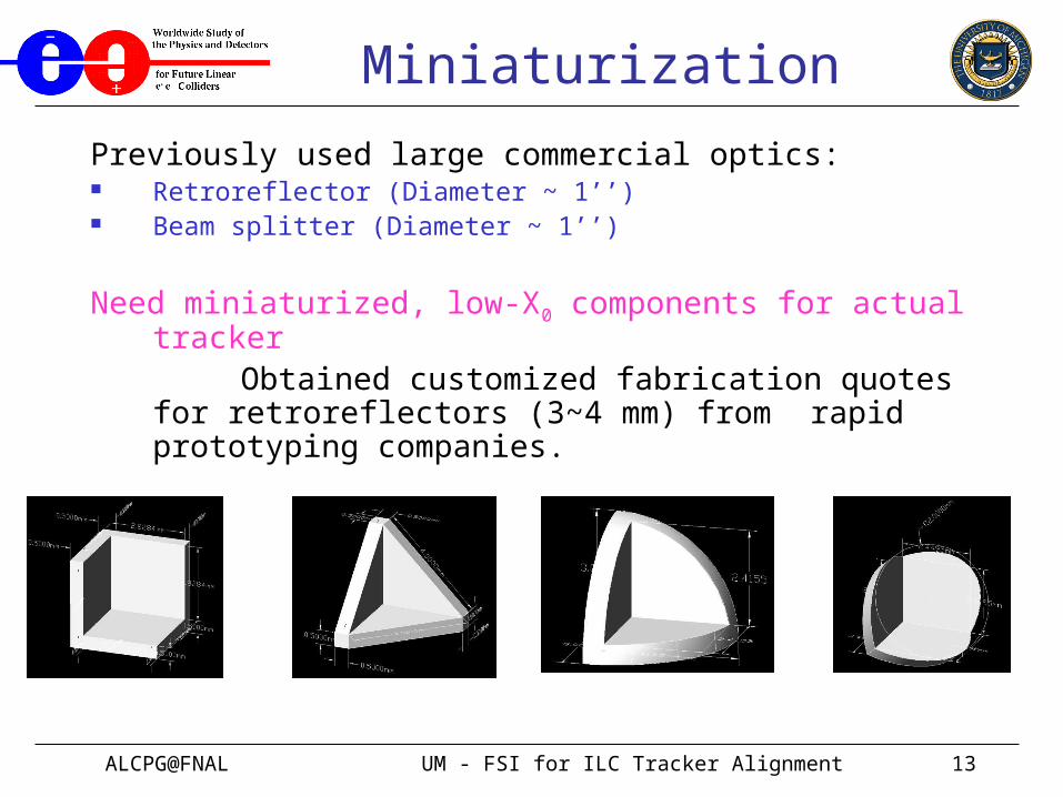
Miniaturization
Previously used large commercial optics: Retroreflector (Diameter ~ 1’’) Beam splitter (Diameter ~ 1’’)
Need miniaturized, low-X0 components for actual tracker Obtained customized fabrication quotes for
retroreflectors (3~4 mm) from rapid prototyping companies.

ALCPG@FNAL UM - FSI for ILC Tracker Alignment 14
Miniaturization
Cheap prototype alternatives: a bicycle reflector:(all but one pixel masked off)
Measurement precision for a distance of 18 cm: ~ 0.4 μm
Promising indication, given simple design of the reflector pixels
( solid plastic corner cubes with no coating,
but low reflective efficiency )

ALCPG@FNAL UM - FSI for ILC Tracker Alignment 15
Miniaturization
Now using Edmund corner cube array, 9 X 9 hexagon corner cubes in 35 mm X 35 mm. Center-to-center spacing of two adjacent corner cubes is ~ 4 mm.
The reflective efficiency of single corner cube is comparable to large commercial corner cube and hollow retroreflector ( D = 1 inch ).
High reflective efficiency is vital to make qualified fringes and to make more channels.
Under controlled conditions L = 417198.37 +/- 0.07 microns The corner cube array has high reflective efficiency and
qualified fringes. It’s very promising.

ALCPG@FNAL UM - FSI for ILC Tracker Alignment 16
We are implementing multi-channels fed by an optical fiber splitter
Double-check systematics
Implement multiple distance measurements and test over- constrained algorithm for a prototype set of reference points
Preparation for test of silicon ladder prototype alignment
Multiple channels
Results not ready yet !

ALCPG@FNAL UM - FSI for ILC Tracker Alignment 17
Simulation To evaluate the impact of distortion of silicon ladder on charged track
momentum reconstruction/measurement.
Integrated track generation, reconstruction and FSI fitting
Inputs: charged track with given momentum, 5 silicon layers based on nominal SiD design, magnetic field B = 5 Tesla.
-- Assume spatial resolution is 7 microns for hits.-- Distortions: rotations, translations, thermal expansion or
contractions of silicon ladders.-- Applying FSI line-of-sight grid constraint (code not fully debugged – premature to show results,
but consistent with earlier simulations.)
Outputs: reconstructed momentum of charged track, event displays for SiD Tracker

ALCPG@FNAL UM - FSI for ILC Tracker Alignment 18
Example Tracks (side view)
Can zoom in on specific locations

ALCPG@FNAL UM - FSI for ILC Tracker Alignment 19
Normal (= 7 microns for hits)
Ptrue = 100 GeV, hit smearing ~ 7 microns
Prec-Ptrue (GeV)

ALCPG@FNAL UM - FSI for ILC Tracker Alignment 20
Normal (= 20 microns for hits)
Ptrue = 100 GeV, hit smearing ~ 20 microns
Prec-Ptrue (GeV)
ALCPG@FNAL UM - FSI for ILC Tracker Alignment 21
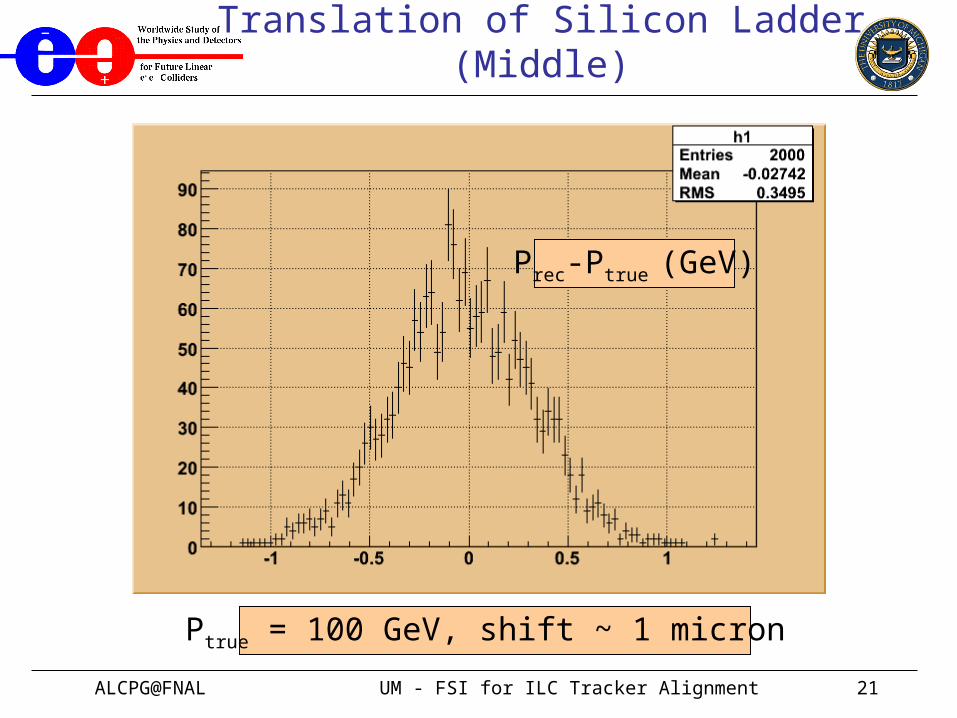
Translation of Silicon Ladder (Middle)
Ptrue = 100 GeV, shift ~ 1 micron
Prec-Ptrue (GeV)

ALCPG@FNAL UM - FSI for ILC Tracker Alignment 22
Translation of Silicon Ladder (Middle)
Ptrue = 100 GeV, shift ~ 10 microns
Prec-Ptrue (GeV)

ALCPG@FNAL UM - FSI for ILC Tracker Alignment 23
Translation of Silicon Ladder (Middle)
Ptrue = 100 GeV, shift ~ 100 microns
Prec-Ptrue (GeV)

ALCPG@FNAL UM - FSI for ILC Tracker Alignment 24
Translation of Silicon Ladder (Middle)
Ptrue = 100 GeV, shift ~ 10 -100 microns
Prec-Ptrue (GeV)

ALCPG@FNAL UM - FSI for ILC Tracker Alignment 25
Rotation of Silicon Ladder (Middle)
Ptrue = 100 GeV, Rotate ~ 1*10-6 rad
Prec-Ptrue (GeV)

ALCPG@FNAL UM - FSI for ILC Tracker Alignment 26
Rotation of Silicon Ladder (Middle)
Ptrue = 100 GeV, Rotate ~ 1*10-5 rad
Prec-Ptrue (GeV)

ALCPG@FNAL UM - FSI for ILC Tracker Alignment 27
Rotation of Silicon Ladder (Middle)
Ptrue = 100 GeV, Rotate ~ 1*10-4 rad
Prec-Ptrue (GeV)

ALCPG@FNAL UM - FSI for ILC Tracker Alignment 28
Summary
Several FSI demonstration systems with increasing realism have been implemented
Results on achievable measurement precision are quite promising (~ 0.2 microns with dual-laser scanning)
Published Results
Hai-Jun Yang, Sven Nyberg, Keith Riles, " High-precision Absolute Distance Measurement using Dual-Laser Frequency Scanned Interferometry Under Realistic Conditions ", Nucl. Instrum. & Meth. A575 (2007) 395-401
Hai-Jun Yang, Jason Deibel, Sven Nyberg, Keith Riles, " High-precision absolute distance and vibration measurement using frequency scanned interferometry", Applied Optics, Vol.44 (2005) 3937-3944

ALCPG@FNAL UM - FSI for ILC Tracker Alignment 29
Summary
Ongoing work: Miniaturization:
baseline retroreflector is plexiglass, but want to investigate other materials (constrained by available prototyping funds)
Multiple channels:
dual-channel system nearly ready
Simulations:
integrated framework nearly complete,
early results seem promising

ALCPG@FNAL UM - FSI for ILC Tracker Alignment 30
Backup Slides

ALCPG@FNAL UM - FSI for ILC Tracker Alignment 31
Fringe Interpolating Technique
5 FSRs
Fringe phase = I+I Fringe phase = J+J
Fringe correction (N_corr) must satisfy: minimize | N_corr+(J+J)-(I+I)-N_average |Where, N_corr is integer number, N_average isexpected average fringe numbers (real) for the given number of FSRs. Expected fringes for 5 FSRs
Laser #1 data with chopper Laser #1 data without chopper

ALCPG@FNAL UM - FSI for ILC Tracker Alignment 32
Distance Measurement Precision
Dual-Laser FSI Data Samples – Under Realistic Conditions * with box open(20 scans), with fan on (10 scans), with vibration(8 scans).
* Scanning rates for Laser #1 and #2 are -0.4 and 0.4 nm/s, respectively.
* Scanning time is 25 seconds, sampling rate is 100 KS/s.
* Two lasers are operated simultaneously, 2-blade chopper frequency is 20 Hz.

ALCPG@FNAL UM - FSI for ILC Tracker Alignment 33
FSI Cross Checks
Used a Micrometer to change the position of retroreflector by large amount (127+/- 3 microns), and check FSI performance. Laser #1, 5 full scan data for each independent test.
dR1 = 128.68 +/- 0.46 microns
dR2 = 129.55 +/- 0.63 microns
dR3 = 127.44 +/- 0.63 microns
dR4 = 124.90 +/- 0.48 microns
Used a Piezoelectric transducer (PZT, 20% tolerance) to change the position of the retroreflector by 2.0 +/- 0.4 microns. Laser #1, 5 full scans for each test.
dR5 = 2.33 +/- 0.12 microns
dR6 = 2.23 +/- 0.07 microns
Single-laser scans – unstable temps
Single-laser scans – stable temps

ALCPG@FNAL UM - FSI for ILC Tracker Alignment 34
FSI Thermal Test
To verify correct tracking of large thermal drifts, we placed a heating pad on a 1’ X 2’ X 0.5’’ Aluminum breadboard
Test 1: increased temperature by 6.7 +/- 0.1 oC
dR_expected = 62.0 +/- 0.9 microns
dR_measured = 61.72 +/- 0.18 microns
Test 2: increased temperature by 6.9 +/- 0.1 oC
dR_expected = 64.4 +/- 0.9 microns
dR_measured = 64.01 +/- 0.23 microns
Test 3: increased temperature by 4.3 +/- 0.1 oC
dR_expected = 39.7 +/- 0.9 microns
dR_measured = 39.78 +/- 0.22 microns
Test 4: increased temperature by 4.4 +/- 0.1 oC
dR_expected = 40.5 +/- 0.9 microns
dR_measured = 41.02 +/- 0.21 microns
Dual-laser scans closed box


![Sistema Eui[1]](https://img.dokumen.tips/doc/110x75/55cf982d550346d033960ed3/sistema-eui1.jpg)