Embed Size (px)
Citation preview
Unsteadiness in Flow over a Flat Plate at
Angle-of-Attack at Low Reynolds Numbers∗
Kunihiko Taira†, William B. Dickson‡, Tim Colonius§, Michael H. Dickinson¶
California Institute of Technology, Pasadena, California, 91125
Clarence W. Rowley‖
Princeton University, Princeton, New Jersey, 08544
Flow over an impulsively started low-aspect-ratio flat plate at angle-of-attack is inves-tigated for a Reynolds number of 300. Numerical simulations, validated by a companionexperiment, are performed to study the influence of aspect ratio, angle of attack, and plan-form geometry on the interaction of the leading-edge and tip vortices and resulting lift anddrag coefficients. Aspect ratio is found to significantly influence the wake pattern and theforce experienced by the plate. For large aspect ratio plates, leading-edge vortices evolvedinto hairpin vortices that eventually detached from the plate, interacting with the tip vor-tices in a complex manner. Separation of the leading-edge vortex is delayed to some extentby having convective transport of the spanwise vorticity as observed in flow over elliptic,semicircular, and delta-shaped planforms. The time at which lift achieves its maximum isobserved to be fairly constant over different aspect ratios, angles of attack, and planformgeometries during the initial transient. Preliminary results are also presented for flow overplates with steady actuation near the leading edge.
I. Introduction
In recent years, flows around flapping insect wings have been investigated and, in particular, it hasbeen observed that the leading-edge vortex (LEV) formed during stroke reversal remains stably attachedthroughout the wing stroke, greatly enhancing lift.1,2 Such LEVs are found to be stable over a widerange of angles of attack and for Reynolds number over a range of Re ≈ O(102) − O(104). Motivatedby the aerodynamic benefits of a stable LEV, a multidisciplinary university research initiative (MURI)has been undertaken to investigate using closed-loop control of actuators along the leading edge and tipof conventional translating airfoils to stabilize the LEV.3,4 In the present paper, we investigate the flowstructure and resulting forces on low-aspect-ratio flat plate at low Reynolds number. Since most of theresearch effort in biological flight is directed toward understanding revolving and flapping flights, there is alack of documentation for translating wings at low Re. There also is a scarcity of three-dimensional studiesof flow around low-aspect ratio wings at low Re in general. The lower end of translating flight studies forlow aspect ratio wings have been experimentally reported by Torres and Mueller5 with Re ≥ 7 × 10⁴. Our
∗Work supported by a Multidisciplinary Research Initiative from the United States Air Force Office of Scientific Research(FA9550-05-1-0369, Program Manager: Dr. Fariba Fahroo).
†Ph.D. Candidate, Mechanical Engineering, Student Member AIAA‡Postdoctoral Scholar, Bioengineering, Member AIAA§Professor, Mechanical Engineering, Member AIAA¶Professor, Bioengineering. Member AIAA‖Assistant Professor, Mechanical and Aerospace Engineering, Member AIAA
1 of 16
American Institute of Aeronautics and Astronautics

intent is to investigate the general behavior of flow around translating wings at Re ≈ O(102) with a numberof aspect ratios, angles of attack, and planform geometries.
Both two- and three-dimensional numerical simulations with an immersed boundary method are usedto analyze the flow field over flat-plate airfoils. The solution is first validated for flow over a rectangularflat plate of A = 2 at Re = 100 with measurements from a companion tow-tank experiment equippedwith stereo digital particle image velocimetry (DPIV) capability and a six-axis force sensor. In this study,we define the Reynolds number, Re, and aspect ratio of the flat plate, A, as Re ≡ U∞c̄
ν and A ≡ Ac̄ ,
where U∞, A, and c̄ are the freestream velocity, the planform area of the plate, and the mean chord ofthe plate, respectively. For the spacial case of two-dimensional simulations, we express the aspect ratio asA = ∞. Once the numerical results are validated, a number of simulations are carried out for a slightlyhigher Reynolds number of Re = 300. This Reynolds number is selected as it is past the critical Reynoldsnumber for a sphere, beyond which the flow is unsteady and vortex shedding occurs. Aspect ratio (A), anglesof attack (α), and the planform geometry are varied to study their effect on the vortical structure behindthe plate and the corresponding lift and drag coefficients. Finally, some preliminary results with modeledleading-edge actuation (steady blowing) are presented. A companion paper4 considers reduced-order modelwith balanced proper orthogonal decomposition method to develop feedback control to stabilize LEV over aplate.
II. Simulations
A. Numerical Method
Simulations of incompressible viscous flow over flat plates are performed with an immersed boundarymethod.6,7 Immersed boundary methods allow the computational domain to be discretized with a non-body conforming Cartesian grid by applying appropriate boundary force along the immersed surface tosatisfy the no-slip condition. We apply a new formulation of the immersed boundary method with a struc-ture algebraically identical to the traditional fractional step method.8 This method is based on a finitevolume staggered grid discretization and is capable of computing flow over stationary or moving bodies.
The continuous analog of the immersed boundary formulation can be represented by
∂u∂t
+ u · ∇u = −∇p +1
Re∇2u +
∫s
f (ξ(s, t)) δ(ξ − x)ds, (1)
∇ · u = 0, (2)
u(ξ(s, t)) =∫x
u(x)δ(x− ξ)dx = uB(ξ(s, t)), (3)
where u, p, and f are the appropriately non-dimensionalized velocity, pressure, and surface force. Thespatial variable in the computational domain D and along the immersed boundary ∂B are denoted by x andξ, respectively. Note that we have written the no-slip boundary condition in terms of a kinematic constraintinvolving a Dirac delta function.
While details are omitted, the above system of Eqs. (1-3) can be discretized in the following manner toyield a system of linear equations for the velocity, pressure, and boundary forces at the next time tn+1:[
A Q
QT 0
](qn+1
λ
)=
(r1
r2
). (4)
Here qn+1 is the discrete velocity vector and λ = [p, f̃ ]T is a set of Lagrangian multipliers consisting ofpressure and boundary force. The current method highlights the analogous roles of pressure and boundaryforce in enforcing the kinematic constraints of divergence-free and no-slip on the velocity field. Matrix Ais an implicit operator for qn+1 and matrix Q = [G, H] is composed of two operators, namely the discretegradient (G) and regularization (H) operators. The right-hand-side vector, (r1, r2)T , is an explicit term
2 of 16
American Institute of Aeronautics and Astronautics

based on the old time steps and boundary conditions. The kinematic constraints are represented by thesecond row of the above equation.
One can then perform an approximate LU decomposition9 of Eq. (4) and solve for the flow field in threesteps:
Aq∗ = r1, (Solve for intermediate velocity) (5)
QT BNQλ = QT q∗ − r2, (Solve the modified Poisson equation) (6)
qn+1 = q∗ −BNQλ, (Projection step) (7)
where BN is the N -th order approximation of A−1 in time. The current formulation is similar to thetraditional fractional step methods but with two major differences. First, the Poisson equation is modified tosimultaneously solve for the pressure and boundary force implicitly. Second, the intermediate velocity vectorq∗ is projected onto the solution space where both divergence-free and no-slip conditions are satisfied. Becausethe boundary force is determined implicitly without any constitutive relations, the present formulation canuse larger CFL numbers compared to some past methods. Symmetry and positive-definiteness of the systemare preserved such that the conjugate gradient method can be used to solve for the flow field efficiently. Thisformulation is found to be second order accurate in time and better than first order accurate in space in theL2 sense.8
B. Simulation Setup
Three-dimensional simulations of flow over low-aspect ratio plates are performed in a large rectangular boxof size [−4, 6.1]× [−5, 5]× [−5, 5] in the streamwise (x), vertical (y), and spanwise (z) directions with a gridsize of 125 × 55 × 80. Two-dimensional flow simulations are also considered with a computational domainof [−15, 15]× [15, 15] in the streamwise (x) and vertical (y) directions with a grid size of 400× 200. In bothcases, the spatial variables are non-dimensionalized by the mean chord c̄ of the plate. Grid stretching isapplied in all directions with finer resolution near the plate to capture the wake structure as illustrated inFigure 1. To ensure that flow field is well resolved, a finer grid with a size of 150×66×96 has also been usedresulting in less than 5% difference in the solution for the three dimensional cases. For the two-dimensionalcases, similar tests have been performed to verify the grid resolution and domain size.
Boundary conditions along all sides are set to uniform flow (U∞, 0, 0) except for the outlet boundarywhere a convective boundary condition (∂u
∂t +U∞∂u∂x = 0) is applied. Inside the computational domain, a flat
plate is positioned with its center of mass at the origin. This flat plate is instantaneously generated at t = 0in an initially uniform flow to model an impulsively started translating plate. Computations are performedto capture the behavior of both the initial transient and the long time flows.
The forces on the flat plate (Fx, Fy) are described in terms of the lift and drag coefficients defined by
CL =Fy
12ρU2
∞Aand CD =
Fx12ρU2
∞A, (8)
where ρ is the freestream density of the fluid. We report all spatial and temporal variables in non-dimensionalunits normalized by the mean chord and the freestream velocity (i.e. x/c̄ and tU∞/c̄).
Numerical results are compared to experimental measurements for flow over a rectangular flat plate ofA = 2 at Re = 100. Once the numerical solution is validated, a number of simulations are performed atRe = 300 for rectangular plates of different aspect ratios for a range of angles of attacks.
Different planform geometries are also considered to investigate the interaction of leading edge and tipvortices. Elliptic, semicircular, and delta-shaped planforms having the same area with the rectangular plateof A = 2 are selected.
3 of 16
American Institute of Aeronautics and Astronautics

(a) (b)
x
y
-4 -2 0 2 4 6-4
-2
0
2
4
x
z
-4 -2 0 2 4 6-4
-2
0
2
4
Figure 1. The computational domains with stretched grid used in the three-dimensional simulations shownfor the (a) xy- and (b) xz-planes (only every third grid is shown). A rectangular plate of A = 2 at α = 30◦ isshown in red for reference.
III. Experimental Validation
Companion experiments are performed in a tow-tank (1m×2.4m×1.2m) filled with mineral oil in whicha rectangular flat plate is translated. The flat plate is rigidly mounted to a six-axis force sensor at one wingtip to limit lift due to backlash in the gearbox. This setup is attached to a translation sled equipped with aservo motor providing control of the translational velocity.10 A constant translation velocity is maintainedby the plate after an initial swift ramping acceleration from rest.
Stereo digital particle image velocimetry (DPIV)11 is used to quantify the flow field around the plate atseveral spanwise positions with a vector field size of 57 × 82. Slices of the flow field are captured from themidspan to 0.22c̄ off the wing tip at eleven locations.
To validate the numerical solution, we consider the force on a rectangular flat plate of A = 2 withRe = 100 at steady statea for a range of angles of attack, α. Figure 2 compares measured lift and dragcoefficients with the simulations. Two sets of numerical results are presented from a case with grid sizeof 125 × 55 × 80 (fine grid) and that with half the grid resolution (coarse grid). There are some minordifferences in the results that are somewhat expected. The experiments are conducted with a finite thicknessplate while the numerical simulation is trying to model an infinitely thin plate, and the force on the platemay be influenced by the presence of the sting on one of the wing tips.
Lift coefficients from experiments and simulations are in agreement over a wide range of α. The maximumdiscrepancy of 7.1% occurs at α = 30◦. Drag coefficients show discrepancy between experiment and the coarsesimulation that is due to the thickness of the flat plate. In experiments, the plate’s thickness is 0.037c̄. Inthe simulations, we attempt to model an infinitely thin plate with regularized body forces. Thus there is aneffective thickness that depends on the grid spacing. Simulations with higher resolution (the stars in Figure2b) provide better agreement for the drag coefficient, with 3.1%, 3.9%, and 5.5% differences at α = 0◦, 30◦,and 90◦, respectivelyb.
Lift coefficients for strictly two-dimensional simulations are also plotted for comparisonc. The pronounceddecrease in lift due to three-dimensionality (induced drag) is evident. The two-dimensional flow becomesunsteady past α ≈ 25◦, resulting in regular vortex shedding. The plus and diamond signs represent the
aVortices around the plate of A = 2 stabilize rapidly after the initial transient for Re = 100. Because the experimentalsetup limited the maximum travel distance to 13 chord lengths, we consider steady-state only in this subsection to be at t = 13for the purpose of validation. Note that the force exerted on the plate decays very slowly past t = 13 in a minor amount.
bDifference normalized by experimentally measured CD at α = 90◦cWe thank Mr. Sunil Ahuja (Princeton University) for providing the two-dimensional data at Re = 100.
4 of 16
American Institute of Aeronautics and Astronautics

maximum and minimum force exerted on the two-dimensional plate by the periodic vortex shedding. Incontrast, the three-dimensional airfoils experience a steady separated flow after an initial transient discussedbelow.
Next, the vorticity fields are compared with the DPIV data in Figure 3. Comparisons are made att = 1.5 and 13 along the mid-span (z = 0). Figure 4 illustrates the three-dimensional structure of thespanwise vorticity distribution at t = 1.5 from both data sets. At this initial stage in time, the LEV isclosely attached to the back of the plate providing enhanced lift compared to steady state. The flow fieldsfrom the numerical solution and the DPIV data are in good agreement. Based on this validation, we nowcontinue to investigate flows around rectangular flat plates with different aspect ratios and angles of attack.
0 10 20 30 40 50 60 70 80 900
0.25
0.5
0.75
1
1.25
1.5
! [deg]
C L
0 10 20 30 40 50 60 70 80 900
0.5
1
1.5
2
! [deg]
C D
Figure 2. Steady state (left) lift and (right) drag coefficients for rectangular flat plate of A = 2 for a rangeof angles of attack at Re = 100. Results shown from experimental measurements (�), simulations with coarsegrid (•), simulations with fine grid (?), and two-dimensional simulations (max: + and min: ♦).
Simulation Experiment
t=
1.5
x
y
-1 0 1 2-1
-0.5
0
0.5
x
y
-1 0 1 2-1
-0.5
0
0.5543210-1-2-3-4-5
t=
13
x
y
-1 0 1 2-1
-0.5
0
0.5
x
y
-1 0 1 2-1
-0.5
0
0.5543210-1-2-3-4-5
Figure 3. Snapshots of spanwise vorticity (ωz) profiles along the midspan (z = 0) at Re = 100 for a rectangularflat plate of A = 2 based on simulations and the DPIV measurements.
5 of 16
American Institute of Aeronautics and Astronautics

Simulation Experiment
Figure 4. Isosurface for the spanwize vorticity of ωz = −4 at t = 1.5 illustrating the LEV formation viewingfrom the rear of the plate (A = 2, Re = 100).
IV. Results
A. Flow over Flat Rectangular Plates
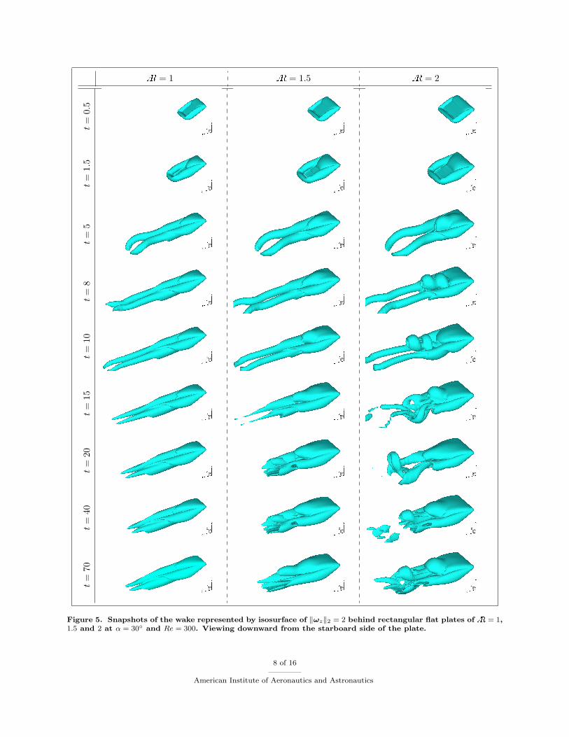
We now investigate the influence of aspect ratio and angle of attack for a slightly higher Reynolds numberof Re = 300. This particular Reynolds number is selected for this study as it is past the critical Reynoldsnumber for flow over a sphere.12 First, we consider flow over flat rectangular plates of different aspect ratios(A = 1, 1.5, 2) at an angle of attack of α = 30◦ from t = 0 to 70. The wake structures behind the plates arecaptured with several snapshots in time by the vorticity iso-surface as shown in Figure 5. The flow exhibitssymmetry about the midspan; attempts to break this symmetry by adding perturbation have not yet beenpursued.
Early in time, the distribution of vorticity around the rectangular plate is similar for all three finite aspectratios. The tip vortices have not yet had much influence on the LEV at this stage. The spanwise vorticityprofile presented for A = 2 at t = 1.5 in Figure 5 shows the LEV located just above the plate. This profileis observed during the start-up transient for all cases including the two-dimensional wing. The structure issimilar to that found in flow over flapping wings.11
Lift and drag histories are presented in Figure 6 for angles of attack 0 < α < 60◦. For all three aspectratios and angles of attack, the lift reaches a maximum around t = 1.5. The universality of this number isdiscussed in more detail below. After this time, the LEV begins to lift off the upper surface resulting in alarger, more diffuse separated region (and a significant drop in lift). For the largest aspect ratio (A = 2)with α > 15◦, the LEV begins to detach around t = 5, and forms a hairpin vortex that is shed into thewake at later time. These hairpin vortices then repeatedly form, detach, and reform through the simulation.There is no highly pronounced vortex shedding frequency based on a spectral analysis performed at largetime up to t = 70. The angle-of-attack at which this shedding first occurs varies; commencing at α > 15◦,20◦, and 30◦ for A = 1, 1.5, and 2, respectively. For A = 2, the angle at which shedding first occursapproaches that for the two-dimensional (A = ∞) case. Thus the aspect ratio has a significant influence onthe wake structure and stability of the LEV.
The behavior of the tip vortices is also different for the different aspect ratios. For t < 8, their structureis similar for all three finite aspect ratios; they grow by rolling up the vortex sheet generated at the wingtips and trailing edge and develop into long columnar streamwise vortices. However, for the larger aspectratio ofA = 2 the shedding of hairpin vortices from the leading-edge produces a strong interaction betweentip and hairpin vortices that gives rise to the irregular shedding. Conversely, the absence of tip vortices inthe two-dimensional cases results in a very regular shedding of the leading-edge and trailing-edge vorticesresembling the Karman vortex street behind a circular cylinder.
6 of 16
American Institute of Aeronautics and Astronautics

Despite their interactions, the leading-edge and tip vortices remain distinct for all three-dimensionalcases. The separation of the vortical structures indicates a lack of any convective vorticity flux in thespanwise direction (i.e. from the midspan to the tips). Figure 7 showing the convective flux of spanwisevorticity, u · ∇ωz, around the plate clearly indicates that there is effectively no spanwise vorticity convectedfrom the LEV into the tip vortices. Such transport has been shown to give rise to stability of the LEV forflapping wings.11 For the translating rectangular wings, there is no mechanism to relieve the vorticity beingfed into the LEVd. Later we consider alternative planform geometries that induce some spanwise flow. Also,in section C, we give some preliminary results on the effect of active control (in the form of a modeled steadymass injection near the leading edge) on the lift generation and LEV stability.
To further contrast the difference between the force exerted by two- and three-dimensional flows, weextract the maximum lift coefficients over time from the initial transients in all cases. The maximum lift fordifferent aspect ratios are plotted as a function of α in Figure 8. Stronger influence of downwash from the tipvortices results in reduced lift for lower aspect ratio plates. For the limiting case of A = ∞, the maximumlift is much higher due to the absence of tip effects. However, there is a favorable feature of the tip vorticesevident in Figure 8 also. While the two-dimensional curve reaches its maximum around α = 35◦, the finiteaspect ratio cases achieve their maxima near α = 45◦. The offset in the angles of attack is caused by thetip vortices supporting prolonged attachment of the LEV at a higher angle of attack for three-dimensionalflows in comparison to the two-dimensional case.
After the initial start-up flow, both lift and drag experienced by the plates are reduced significantly atlarge time as shown in Figure 9 in terms of the time average quantities. Despite the variation in the maximumlift observed in Figure 8 and the fluctuations seen in Figure 6, the time-averaged forces experienced by theplates are nearly the same. Also the magnitude of these forces are much lower, falling to as much as half themaximum value.
Finally, we call attention to the time at which the maximum lift is achieved. We denote this time byt∗ and present its value on Figure 10. It is found that over the considered range of finite aspect ratios andangles of attack, t∗ is fairly constant with a value of t∗ ≈ 1.5 because the profiles of the LEV are similaramong all cases. As the accumulation of spanwise vorticity generated by the leading edge contributes to thegrowth of the LEV, there is reminiscence to the formation number used to describe the time at which vortexrings can no longer grow larger in strength.13 Since formation number is found to be a universal quantity fora variety of flow,14 it is not too surprising that t∗ is also fairly constant for the number of three-dimensionalcases considered here.
In the case of two dimensional flow, we observe a wider range of t∗ between 1.3 and 2.4 for α < 45◦. Athigher α, a second local maximum startes to emerge for the two-dimensional flow lowering t∗ significantly.
B. Effect of Planform Geometry
We now vary the planform geometry at α = 30◦ for Re = 300. Because the rectangular flat plates havestraight leading edges inhibiting spanwise transport of vorticity, we consider elliptic, semicircular, and deltaplanforms to induce spanwise vorticity transport along the leading edge to the tip vortices. The ellipse anddelta planforms haveA = 2 and the semicircle has a similarA = 8/π = 2.546. Geometries are chosen suchthat the area and the mean chord length are identicale to those of the rectangular plate of A = 2, whichis previously observed to have the most unsteadiness in the wake among the finite aspect ratios considered.We discuss the differences in the wake in contrast to the rectangular flat plate of A = 2.
Flow behind different planforms is illustrated in Figure 11. Compared to the rectangular profile, theelliptic and semicircular plates generate wake with a less distinct transition between leading edge and tipvortices due to the vorticity transport from the LEV to the tip vortices. Snapshots of an isosurface of u ·∇ωz
are presented for the three geometries in Figure 12 at t = 5. In all three cases, spanwise vorticity is carriedaway from the leading edge to the tip vortices, which is different from flow around rectangular planforms
dViscous diffusion provides a mechanism to diffuse vorticity out of the LEV, but is apparently too weak at Re = 300 tostabilize the LEV. In the case of Re = 100, the LEV is found to be stable at steady state due to viscous diffusion.
eExcept for the semicircular wing which only has an identical mean chord length.
7 of 16
American Institute of Aeronautics and Astronautics
A = 1 A = 1.5 A = 2t=
0.5
t=
1.5
t=
5t=
8t=
10t=
15t=
20t=
40t=
70
Figure 5. Snapshots of the wake represented by isosurface of ‖ωz‖2 = 2 behind rectangular flat plates of A = 1,1.5 and 2 at α = 30◦ and Re = 300. Viewing downward from the starboard side of the plate.
8 of 16
American Institute of Aeronautics and Astronautics

Lift Drag
A=
1
0 10 20 30 40 50 60 70 010
2030
4050
600
1
2
3
!t
C L
0 10 20 30 40 50 60 70 010
2030
4050
600
1
2
3
!t
C D
A=
1.5
0 10 20 30 40 50 60 70 010
2030
4050
600
1
2
3
!t
C L
0 10 20 30 40 50 60 70 010
2030
4050
600
1
2
3
!t
C D
A=
2
0 10 20 30 40 50 60 70 010
2030
4050
600
1
2
3
!t
C L
0 10 20 30 40 50 60 70 010
2030
4050
600
1
2
3
!t
C D
A=∞
0 10 20 30 40 50 60 70 010
2030
4050
600
1
2
3
!t
C L
0 10 20 30 40 50 60 70 010
2030
4050
600
1
2
3
!t
C D
Figure 6. Lift and drag history on rectangular flat plates of different A for a range of angles of attack atRe = 300 (shown for α = 0, 5, 10, 15, 20, 30, 40, 45, 50, and 60 degrees).
9 of 16
American Institute of Aeronautics and Astronautics
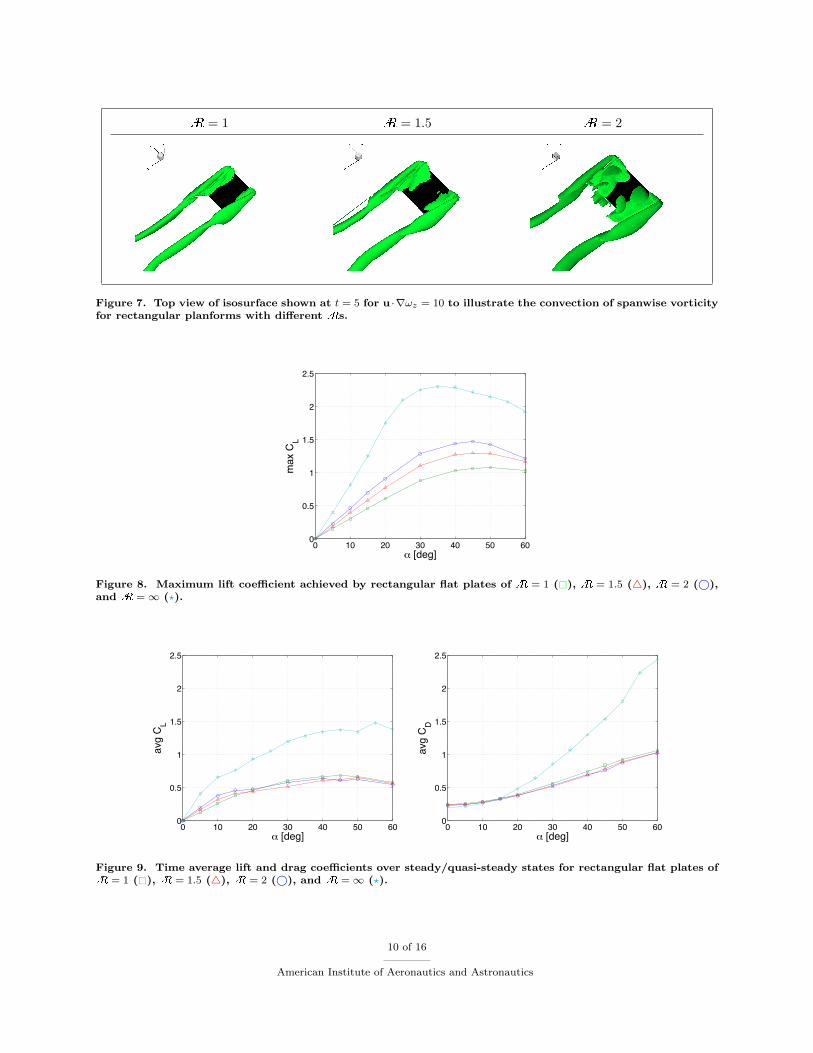
A = 1 A = 1.5 A = 2
Figure 7. Top view of isosurface shown at t = 5 for u ·∇ωz = 10 to illustrate the convection of spanwise vorticityfor rectangular planforms with different As.
0 10 20 30 40 50 600
0.5
1
1.5
2
2.5
! [deg]
max
CL
Figure 8. Maximum lift coefficient achieved by rectangular flat plates of A = 1 (�), A = 1.5 (4), A = 2 (©),and A = ∞ (?).
0 10 20 30 40 50 600
0.5
1
1.5
2
2.5
! [deg]
avg
C L
0 10 20 30 40 50 600
0.5
1
1.5
2
2.5
! [deg]
avg
C D
Figure 9. Time average lift and drag coefficients over steady/quasi-steady states for rectangular flat plates ofA = 1 (�), A = 1.5 (4), A = 2 (©), and A = ∞ (?).
10 of 16
American Institute of Aeronautics and Astronautics

0 10 20 30 40 50 600
0.5
1
1.5
2
2.5
3
! [deg]t*
Figure 10. Time at which maximum lift is achieved by rectangular flat plates of A = 1 (�), A = 1.5 (4), A = 2(©), and A = ∞ (?).
shown in Figure 7. Hence it takes longer time for the LEV to separate from the plate. The leading edgehairpin vortex that is first observed to detach around t ≈ 8 for the rectangular planform separates at muchlater time (t ≈ 15) for elliptic and semicircular plates (Figure 11). Nonetheless, the overall topologies of thevorticity profile are very similar among the wakes behind the rectangular, elliptic, and semicircular plates.
A notably different distribution of vorticity is obtained for the delta wing with A = 2 and a sweepbackangle of 45◦. The absence of wing tips for this planform allows the vortex sheets from the leading edge toroll-up and convect downstream in a very stable manner (see Figures 11 and 12). For this very low Reynoldsnumber of Re = 300, the LEVs are larger compared to ones from higher Reynolds number flow.15 Onecan observe transient behavior of the wake until t ≈ 15 in Figure 11. Beyond this point in time, there aresome unsteady shedding of small vortical structures behind the rolled up vortices. However, the leading edgevortices do not change its shape much past t ≈ 8 achieving a near steady state.
The force experienced by different planforms are compared with that exerted on a rectangular plate ofA = 2 over time on Figure 13. The force history is similar amongst the four geometries considered, consistentwith the findings of Usherwood and Ellington16 for revolving wings at low Reynolds number. Interestingly,the time at which the maximum lift is achieved is again found to be t ≈ 1.5 for the elliptic and semicircularwings.
The two large fluctuations in the lift coefficient around t ≈ 10 for the rectangular plate are not presentfor the other planforms. These two bumps are caused by the two consecutive detachments of leading edgevortices as seen in Figure 5 at t ≈ 8. The prolonged attachment of the LEV eliminates these features. Thevortical structure behind the delta wing does not change much for t > 10. There is some amount of vorticityshedding into the wake but this occurs much further downstream from the main vortical structure. Most ofthe vorticity escapes from the wake to the free stream through diffusion in an undisturbing manner. Thus,the force applied on the body does not fluctuate for large time.
C. Flow over Rectangular Plates with Actuation
Finally, we consider preliminary results using steady active control to the A = 2 rectangular plate at anangle of attack of α = 30◦. A model actuator represented by a strip of external body force is applied to theflow field expressed by fd(x − x0)d(y − y0)H(b/2 + z)H(b/2 − z), where d(·) is the same regularized deltafunction used in the immersed boundary method, H(·) is the Heaviside step function, and b is the span ofthe plate. The direction and the location of the forcing function are defined by the vector f and (x0, y0, z0),respectively, where z0 ∈ [−b/2, b/2]. We set f to be time-invariant for this study to model steady massinjection near the leading edge.
The magnitude of the forcing function is chosen such that the momentum coefficient of the actuator
11 of 16
American Institute of Aeronautics and Astronautics

Ellipse Semicircle Deltat=
0.5
t=
1.5
t=
5t=
8t=
10t=
15t=
20t=
40t=
70
Figure 11. Snapshots of the wake represented by isosurface of ‖ωz‖2 = 2 behind elliptic, semicircular, anddelta-shaped flat plates at α = 30◦ and Re = 300. Viewing downward from the starboard side of the plate.
12 of 16
American Institute of Aeronautics and Astronautics

Ellipse Semicircle Delta
Figure 12. Top view of isosurface shown at t = 5 for u · ∇ωz = 10 to illustrate the convection of spanwisevorticity for elliptic, semicircular, and delta planforms.
0 10 20 30 40 50 60 700
0.2
0.4
0.6
0.8
1
1.2
1.4
1.6
t
C L
0 10 20 30 40 50 60 700
0.2
0.4
0.6
0.8
1
1.2
1.4
1.6
t
C D
Figure 13. History of lift (top) and drag (bottom) over time with Re = 300 and α = 30◦ for different planformgeometries: rectangle of A = 2 ( ); ellipse ( ©); semicircle ( �); and delta ( 4).
13 of 16
American Institute of Aeronautics and Astronautics

model is approximately cµ ≡ ρu2actAact/( 1
2ρU2∞A) ≈ 0.01 for all cases (here uact and Aact are the actuator
velocity and slot area, respectively). This value is an order of magnitude larger than what is used in realactuators17 as this study intends to investigate the fundamental effect of actuation in a preliminary manner.For a more realistic study we would need to use a finer grid to resolve the flow structure in the vicinity ofan actuator.
Steady body force is applied 0.1c above and 0.06c behind and the leading edge with varied forcingdirections. A selection of five forcing angles are made in the streamwise-spanwise (x-z) plane in the directionsof (i) downstream, (ii) 45◦ angled outward from downstream, (iii) spanwise from the midspan to the tips, (iv)45◦ from upstream, and (v) upstream as illustrated in Figure 14. By choosing such directions, the responseof the flow field can be examined for downstream/upstream and spanwise blowing.
(i) (ii) (iii) (iv) (v)
Figure 14. Top view illustration of the actuator directions: (i) downstream; (ii) 45◦ from downstream; (iii)spanwise; (iv) 45◦ from upstream; and (v) upstream. Free stream is directed from left to right.
Lift and drag history with actuation is presented in Figure 15. Actuation for all five cases does not modifythe drag much, but alters the behavior of lift noticeably. Actuation in the streamwise direction enhancesthe lift by approximately 20 to 30% compared to the case of no actuation being applied. This is due to thegeneration of vorticity by the body force that is engulfed into the LEV in addition to what is generated atthe leading edge. Blowing upstream provides an opposite effect of reducing the influx of vorticity into theLEV resulting in less lift. The sideway actuation does not change the force on the body in a significantmanner.
In future investigation, a better position of the actuator model are to be examined, since it is quitedistant from the plate. Feedback control will also be explored. Further simulations with finer resolution areunderway to reduce the momentum coefficient and to investigate flow at higher Re, where the receptivity ofthe flow to actuation may be different.
V. Summary
We presented results from numerical simulations of flows over low-aspect-ratio flat plates at low Reynoldsnumber using an immersed boundary method. Both the initial transient and long time behavior of the flowwas studied by simulating an impulsively started translating plate. Companion experiments were performedin a tow tank to validate the numerical solution with DPIV data and force measurements.
A number of simulations were performed for Re = 300 with varied aspect ratio, angle of attack, andplanform geometry. The aspect ratio was found to have a large influence on the stability of the wake profileand the force experienced by the body. Two-dimensional flows were observed to be vastly different due tothe absence of the tip vortices. Behind rectangular plates ofA = 1.5 and 2, leading-edge vortices were foundto form and eventually separate as hairpin vortices. The detached structure would then interact with thetip vortices in a complex manner. Prior to the first separation of the hairpin vortex, the flow profile behindthe plates is found to be similar to what has been observed for flapping and revolving wings.
Planform geometries of elliptic, semicircular, and delta were also considered. By providing curvaturealong the leading edge, convective transport of vorticity from the midspan to the tip somewhat delayed the
14 of 16
American Institute of Aeronautics and Astronautics

0 10 20 30 40 50 60 700
0.2
0.4
0.6
0.8
1
1.2
1.4
1.6
t
C L
0 10 20 30 40 50 60 700
0.2
0.4
0.6
0.8
1
1.2
1.4
1.6
t
C D
Figure 15. History of lift (top) and drag (bottom) over time for a rectangular plate of A = 2 at α = 30◦ andRe = 300 with actuation in different directions: (i) ©; (ii) �; (iii) 4; (iv) ?; and (v)
♦. No actuation shown with .
15 of 16
American Institute of Aeronautics and Astronautics

separation of the LEV. In the case of the delta wing, the leading edge structure was able to remain attachedin a very stable manner.
It was observed for most of the cases that maximum lift in time was achieved at a non-dimensional timearound t∗ ≈ 1.5 regardless of the aspect ratio, angle of attack, and planform geometry. We commented onthe reminiscence to the formation number and its possible universality of this non-dimensional time.
Finally, some preliminary results were presented for flow over rectangular plate of A = 2 with modeledsteady mass injection near the leading edge. As an initial study to understand the response of the flow, arather large momentum coefficient of 0.01 is used. Downstream blowing was found to increase lift but createdlarger fluctuations over time. Actuation in spanwise and upstream directions were not observed to enhancelift. However, further studies with finer resolution and smaller momentum coefficient for the actuator needto be considered to deduce concrete conclusion.
References
1C. P. Ellington, C. van den Berg, A. P. Willmott, and A. L. R. Thomas, “Leading-edge Vortices in Insect Flight,” Nature,Vol. 384, pp. 626-630.
2J. M. Birch, W. B. Dickson, and M. H. Dickinson, “Force Production and Flow Structure of the Leading Edge Vortex onFlapping Wings at High and Low Reynolds Numbers,” Journal of Experimental Biology, Vol. 207, pp. 1063-1072, 2004.
3T. Colonius, C. W. Rowley, G. Tadmor, D. R. Williams, K. Taira, W. B. Dickson, M. Gharib, and M. Dickinson, “Closed-Loop Control of Leading-Edge and Tip Vortices for Small UAV,” Conference on Active Flow Control, DFG, Berlin, Sep. 27-29,2006.
4S. Ahuja, C. W. Rowley, I. G. Kevrekidis, T. Colonius, and G. Tadmor, “Low-Dimensional Models for Control of Leading-Edge Vortices: Equilibria and Linearized Models,” 45th Aerospace Sciences Meeting and Exhibit, AIAA, (AIAA 2007-709),Reno, NV, Jan. 8-11, 2007.
5G. E. Torres and T. J. Mueller, “Low-Aspect-Ratio Wing Aerodynamics at Low Reynolds Numbers,” AIAA Journal, Vol.42, No. 5, pp. 865-873, 2004.
6C. S. Peskin, “The Immersed Boundary Method,” Acta Numerica, Vol. 11, pp. 479-517, 2002.7R. Mittal and G. Iaccarino, “Immersed Boundary Methods,” Annual Review of Fluids Mechanics, Vol. 37, pp. 239-261,
2005.8K. Taira and T. Colonius, “The Immersed Boundary Method: A Projection Approach,” Journal of Computational Physics,
submitted, 2006.9J. B. Perot, “An Analysis of the Fractional Step Method,” Journal of Computational Physics, Vol. 108, pp. 51-58, 1993.10W. B. Dickson and M. H. Dickinson, “The Effect of Advance Ratio on the Aerodynamics of Revolving Wings,” Journal
of Experimental Biology, Vol. 207, pp. 4269-4281.11C. Poelma, W. B. Dickson, and M. H. Dickinson, “Time-Resolved Reconstruction of the Full Velocity Field Around a
Dynamically-Scaled Flapping Wing,” Experiments in Fluids, Vol. 41, pp. 213-225, 2006.12T. A. Johnson and V. C. Patel, “Flow past a sphere up to a Reynolds number of 300,” Journal of Fluid Mechanics, Vol.
378, pp. 19-70, 1999.13M. Gharib, E. Rambod, and K. Shariff, “A Universal Time Scale for Vortex Ring Formation,” Journal of Fluid Mechanics,
Vol. 360, pp. 121-140, 1998.14D. Jeon and M. Gharib, “On the Relationship Between the Vortex Formation Process and cylinder Wake Vortex Patterns,”
Journal of Fluid Mechanics, Vol. 519, pp. 161181, 2004.15I. Gursul, M. R. Allan, and K. J. Badcock, “Opportunities for the Integrated Use of Measurements and Computations
for the Understanding of Delta Wing Aerodynamics,” Aerospace Science and Technology, Vol. 9, pp. 181-189, 2005.16J. R. Usherwood and C. P. Ellington, “The Aerodynamics of Revolving Wings, I. Model Hawkmoth Wings,” Journal of
Experimental Biology, Vol. 205, pp. 1547-1564, 2002.17D. Greenblatt and I. J. Wygnanski, “The Control of Flow Separation by Periodic Excitation,” Progress in Aerospace
Sciences, Vol. 36, pp. 487-545, 2000.
16 of 16
American Institute of Aeronautics and Astronautics