Embed Size (px)
Citation preview

UNLV Research Foundation High Temperature Heat Exchanger Development
Anthony E. Hechanova, Project Manager
University of Nevada, Las Vegas
This presentation does not contain any proprietary or confidential informationPDP 24

2
Overview
• Project start date: 9/03• Project end date: 9/08• Percent complete: 75%
• Barriers addressedNuclear Hydrogen Initiative R&D Plan –
Material performance and component design and testing for the intermediate heat exchanger and high-temperature thermochemical water splitting (H2SO4decomposition and HI decomposition). Improved materials for High Temperature Electrolysis.
• Total project funding– DOE/NE: $7,700k
• Funding received in FY06: $1,870k
• Funding for FY07: $2,000k
Budget
Timeline Barriers
• UNLV, UC Berkeley, MIT, General Atomics, Ceramatec, Argonne National Lab
Partners

3
ObjectivesTo assist DOE-NE in the development of
hydrogen production from nuclear energy through:
• Identification and testing of candidate materials and coolants for heat exchanger components.
• Design of critical components in the interface and sulfur iodine thermochemical process.
• Fabrication and testing of prototypical components.
• Innovative materials development.

4
Approach• Task 1: Heat Exchanger Component
Design – Examination of flow distribution in off-
set strip fin HTHX– Numerical analyses with chemical
reactions, thermal hydraulic and stress for Ceramatec sub-mm channel sulfuric acid decomposer
– Numerical analysis of bayonet-type sulfuric acid decomposer
– Conceptual design and numerical analysis of shell and tube type heat exchangers for chemical decomposition
• Task 2: Identification and testing of candidate metallic materials for heat exchanger components
– Evaluation of material strength, crack propagation, and corrosion properties
– Materials tested: Alloy C-22, C-276, 617, and 718 up to 1000 C
– Nb-7.5Ta up to 400 C (for HI decomposition)
• Task 3: Heat Exchanger Prototype Testing– Experiments with surrogate materials to
validate hydrodynamic and overall heat transfer coefficients from CFD results
– Prototype to model ratio is 1:3 for the off-set strip fin design
• Task 4: Analytical Studies of the Effects of Acid Exposure on Structure Materials
– Elemental analysis and bonding structure to identify phenomena (e.g. oxide formation and thickness)
• Task 5: Efficiency Improvement and Cost Reduction of Solid Oxide Electrolysis Cells
– Understand processes at surfaces and interfaces to identify degradation mechanisms, study interfacial phases, and elucidate preferred sites for oxygen diffusion and evolution
– Surface sensitive techniques are used to determine chemical composition and electronic properties. Scanning Probe Microscopy and Spectroscopy provide morphology and local electronic properties with atomic resolution

5
Approach• Task 6: Corrosion and Crack Growth
Studies of Materials in HIxEnvironment– Long-term testing of qualified
candidates in both static and flow environments
– Stress corrosion testing to study crack initiation and growth
– Testing the effect of chemical contaminations
• Task 7: Ceramic-Based High Temperature Heat Exchanger Development– Testing of candidate materials
(silicon carbide, silicon nitride, and alumina) for corrosion properties in high temperature gaseous and boiling environments
– Design and fabrication of full-sized wafers
– Develop heat exchanger design concepts for oxygen chillers
• Task 8: Materials Design and Modeling for C/SiC Compact Ceramic Heat Exchangers
– Analyze ceramic compact heat exchanger design and liquid salt coolant for intermediate HTHX
– Model transient response of intermediate heat exchanger
– Analyze liquid salt chemistry, corrosion control, and tritium transport
• Task 9: Development of Self Catalytic Materials for Thermo-chemical Water Splitting Using the Sulfur-Iodine Process
– Characterize the catalytic effectiveness of Alloys 617 and 800H with Pt experimentally with SO3 at high temperatures
– Characterize electrochemical behavior by examining microstructure using Scanning Electron Microscopy
– Selected compositions: Alloy 617 and 800H with 1 and 2 wt% Pt and 800H with 5 wt% Pt

6
Accomplishments: Task 1: Heat Exchanger Component Design• Offset Strip Fin Heat Exchanger (UCB design)
– Optimized design– Mass flow rates distribution in the inside channels are close to uniform distribution. The configuration of the inlet manifold for the liquid-salt
part is acceptable if a maximum difference of 15% could be tolerated.• Compact Heat Exchanger for Chemical Reactions (Ceramatec, Inc. design)
– The baseline design of a straight channel heat exchanger has 90% thermal efficiency. Alternative designs enable an increase in efficiency up to 96% (diamond-shaped channel design). The cost of the added efficiency is more complex channels geometry and increased pressure drop.
– The SO3 decomposition percentage for the baseline design is 64%. The decomposition percentage can be increased by reducing reactant mass flow rate and increasing channel length and operating pressure all leading to increased residence time.
– Because of non-uniformity of the flow distribution among the channels for the baseline design three improved plate and manifold designs were investigated that resulted in a more uniform flow rate distribution. The most preferable design has the lowest nonuniformityparameter and overall pressure drop.
– The thermal/mechanical stress analysis showed that all the considered designs have an acceptable factor of safety under the proposed operating conditions.
• Bayonet Type Heat Exchanger and Chemical Decomposer (SNL design)– Calculation of the processes in the bayonet heat exchanger and decomposer for the baseline design and conditions has been completed.
The SO3 decomposition percentage obtained by numerical calculations is found to be in the same range as experimental observations.
– Parametric studies of the bayonet heat exchanger and decomposer for different surface-to-volume ratios, Reynolds number and operating pressures were performed. Results showed that the decomposition percentage increases with an increase in surface-to-volume ratio and operating pressure and a decrease in Reynolds number which agrees with the general observations.
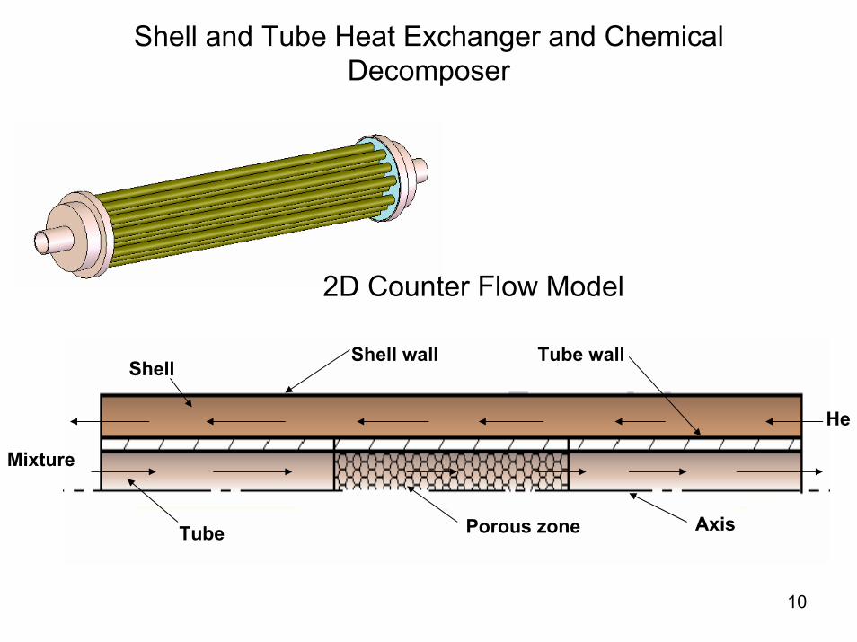
• Shell and Tube Heat Exchanger and Chemical Decomposer (UNLV/INL design)
– A shell and tube heat exchanger with a catalytic bed inside the tubes was proposed for SO3 decomposition. The calculated decomposition for the baseline design and operating conditions is very high for the both counter and parallel flow arrangements (more than 90%). One reason is because the reactant mass flow rate is very low and, consequently, residence time is very high.
– Based on a parametric study, it was found that the SO3 decomposition percentage decreases with increased Reynolds number and increased tube diameter.
– A parametric study of different mass flow rates of helium passing through the shell was accomplished. The SO3 decomposition increases as the mass flow rate of helium through the shell increases. A parametric study of different diameters of the shell was also performed.

7
Offset Strip Fin Heat Exchanger: Velocity Distribution in Liquid Salt Section

8
Compact Heat Exchanger for Chemical Reactions (Ceramatec, Inc. design): Reacting Flow Streamlines (velocity magnitude, m/s)
Two hexagonal layersunder 50% of layers overlapping
Two hexagonal layersunder 100% of layers overlapping
Diamond-shaped channel

9
Bayonet Type Heat Exchanger
DecomposerDecomposer
SuperheaterSuperheater
BoilerBoiler
Temperature and Pressure in the Decomposer
10
Shell and Tube Heat Exchanger and Chemical Decomposer
Shell wall
Tube Porous zone
Tube wall
Axis
He
Mixture
Shell
2D Counter Flow Model
11
Accomplishments: Task 2: Identification and testing of candidate metallic materials for heat exchanger components
• The tensile parameters (the yield strength (YS), the ultimate tensile strength (UTS), the percent elongation (%El) and the percent reduction in area (%RA) ) of Alloys C-22, C-276, 617 and 718 at temperatures ranging from ambient to 1000 C were completed.
• The reduced ductility in terms of %El and %RA within certain temperature regimes has been attributed to the occurrence of dynamic-strain-aging (DSA) behavior of susceptible materials related to the diffusion of solute elements and their accumulation near the grain boundaries. The reduced dislocation mobility through grain boundaries can lead to reduced plastic strain in terms of failure strain (ef) or %El. Transmission Electron Microscopy (TEM) was used to determine the dislocation density (ρ) in specimens tested in the susceptible temperature regime.
• The determination of fracture toughness (KIC) using compact tension (CT) specimens of nickel-base alloys is in progress.
• Crack propagation study involving double-cantilever-beam (DCB) specimens of Alloy C-22 is ongoing in a 100 C acidic solution.
• Transmission electron microscopy (TEM) was used to characterize dislocations using the resultant micrographs and superimposition of grids onto them. The results indicate that the magnitude of dislocation density (ρ) was highest at temperatures in the vicinity of 200 and 300 C (C-276), where reduced plastic strains were noted. The magnitude of ρ was relatively lower at 450 C due to enhanced dislocation mobility and ease of plastic deformation.
• Since the phenomenon of DSA is influenced by both temperature and strain rate, the effects of both these parameters on the activation energy were studied. An average Q value of 55 kJ/mole was calculated based on these analyses.
• Non-linear relationship was noted in log true stress (σ) vs. log true strain (ε) plot according to the Hollomon equation. Therefore, Ludwigson approach was applied to determine the magnitude of n that ranged between 0.68 and 0.75 for specimens tested at 200, 300, 400 and 450 C.
• The susceptibility of Alloy C-276 to stress corrosion cracking (SCC) in room temperature acidic solution (PH~1) was determined by using precracked and wedge-loaded double-cantilever-beam (DCB) specimens. Measurable crack extension and reduced stress intensity factor values were observed upon completion of 30 days tests. Studies with C-22 are ongoing.
• The Scanning Electron Microscopy (SEM) micrographs of Alloy C-276 revealed dimpled microstructures in tensile testing at temperatures up to 600 C, indicating ductile failures. However, brittle failures were seen at temperatures of 700 and 800 C.
• Fractographic evaluations of the Alloy C-22 specimens by SEM revealed ductile failures up to 500 C, beyond which a combination of ductile and brittle failures was seen.
• The superimposition of the s-e diagrams obtained on Nb7.5Ta at temperatures ranging from ambient to 400 C also indicates the occurrence of DSA, showing the lowest failure strain (ef) at 300 C. The analysis of the TEM micrographs revealed an order of magnitude higher ρ value at 300 C compared to that at room temperature. The SEM micrographs of the specimens tested at different temperatures revealed predominantly ductile failure characterized by dimples.
• The results of SSR testing involving Alloy C-22 indicate that the magnitude of %El, %RA, time to failure (TTF) and true failure stress (σf) was reduced in the presence of acidic solution at 90 C. A similar trend was seen with Nb7.5Ta.

12
Superimposed Engineering Stress vs Strain Diagrams at Different Temperatures for Alloy 617

13
SEM Micrographs of Alloy C-276, 500X
600°C 700°C

14
Determination of Dislocation Density (ρ) by Line Intersection Technique
0 100 200 300 400 5000
10
20
30
40
50
Dis
loca
tion
Den
sity
(no.
/m2 ) X
1014
Temperature (oC)
ρ vs. Temperature (C-276)

15
Accomplishments: Task 3: Heat Exchanger Prototype Testing
• Modeling was completed and prototype (1:3 scale for air and 1:2 for silicon oil) test sections were built with Alloy 6061 and Acrylic sheets (with square-edge-fins and round-edge-fins).
• Air to simulate He and silicon oil to simulate liquid salt were the testing fluids.
• Isothermal and heated tests with air were performed to measure friction factors. Friction factors were calculated and compared with that of the square-edge-fins. The volumetric flow rate was varied and corresponded to a range of Reynolds numbers between 1800 and 2600. The results show that the friction factors of round-edged fins are 40% less than that of the square-edged fins.
• The hydrodynamic tests in an isothermal single-chamber test section with 2 cSt and 5 cSt silicon oils were completed. The experiments were performed using Reynolds numbers variations from 50 to 250 to simulate the prototype heat exchanger flow.

16
Single-chamber Test Sections and Model Streamlines
Schematic diagram of experimental rig
Square-edge-fins Round-edge-fins
StreamlinesRe=2400 and isothermal

17
0
0.05
0.1
0.15
0.2
0.25
0.3
0.35
0 50 100 150 200 250 300
Reynolds Number (Re)Fr
actio
n Fa
ctor
(f)
f_2cStf_5cSt
0
0.01
0.02
0.03
0.04
0.05
0.06
0.07
0.08
1800 2000 2200 2400 2600
Reynolds Number (Re)
Fric
tion
Fact
or (f
)
Flux1_SFlux2_SSquare_isoFlux1_RFlux2_RRound_iso
Friction Factors of Different Fin Shapes Under Isothermal and Heated (Air) Conditions
Air Silicon Oil

18
Nusselt Number versus Reynolds Number with double-sided heating (air is working fluid)
Nusselt Number vs Reynolds Number with Double-heating
12.00
13.00
14.00
15.00
16.00
17.00
18.00
19.00
1800 2000 2200 2400
Reynolds Number (Re)
Nus
selt
Num
ber (
Nu)
Nu_DH1Nu_DH2Nu_DH3
19
Accomplishments: Task 4: Analytical Studies of the Effects of Acid Exposure on Structure Materials
• A corrosion-resistant modulated molecular beam mass spectrometer-monitored vacuum furnace facility was designed.
• The vacuum system was designed to tolerate the acidic and halogen containing compounds used the sulfur-iodine thermochemical process.
• The facility will allow a number of materials related studies, measuring permeation and failure with gas pressure loads under chemical and thermal conditions characteristic of the S-I process.
• X-ray photospectroscopy was used to confirm the formation of a silicon dioxide (silica, SiO2) layer on corrosion samples supplied by Ceramatec, Inc. A layer of silica on the surface of the materials may act to blunt surface flaws and lead to an apparent increase in strength, as measured.
• The surface of silicon carbide samples were slightly rich in carbon after the first corrosion experiment, whereas the surfaces of silicon nitride samples were not.
20
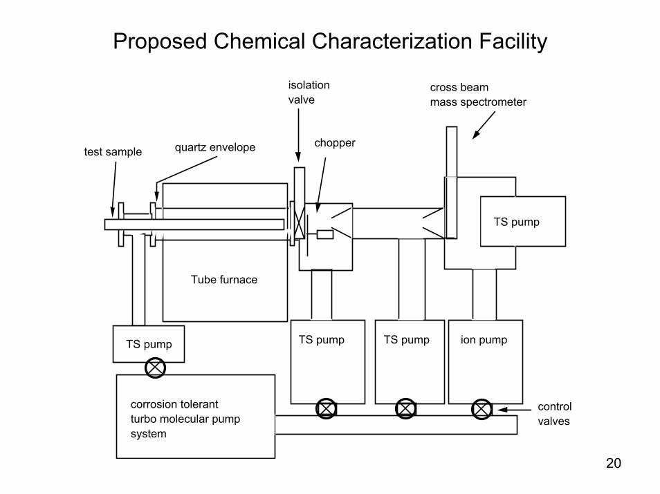
Proposed Chemical Characterization Facility
ion pumpTS pump
TS pump
TS pump
Tube furnace
cross beam mass spectrometer
test sample
corrosion tolerant turbo molecular pump system
control valves
quartz envelope chopper
isolation valve
TS pump

21
Cracked Region of Silicon Carbide Exposed to H2SO4 at ~900 C for 1000 hrs.
Note the oxide in the cracks.

22
Accomplishments: Task 5: Efficiency Improvement and Cost Reduction of Solid Oxide Electrolysis Cells
• Successfully installed new electron spectrometer, scanning probemicroscope, and sample insertion glove box.
• Completed spectral library for commercially available reference compounds.
• X-ray absorption and emission spectroscopy of Lax Sry MnO3 and Lax Sry CoO3 samples received from Argonne National Lab were taken at the Advanced Light Source at LBNL.
• Performed stoichiometry analysis of YSZ thin films deposited by Atomic Layer Deposition (ALD)
• Lax Cay MnO3 (LCM) and Y-stabilized ZrO (YSZ) electrodes prepared by Pulsed Laser Deposition (PLD) were studied with X-ray absorption, emission spectroscopy, Atomic Force Microscopy, and Scanning Probe Microscopy to determine surface composition and chemical structure.
• X-ray absorption was found to be a very sensitive tool to investigate the actual compound and oxidation state of the samples.
• As expected, all samples show characteristic signatures of La, Ca, Mn, and O core levels and Auger transitions. Furthermore, significant C and O contaminations were found on the surface. This is not unexpected, since the surfaces were exposed to air after preparation and during additional tests at ANL.

23Scanning ProbeMicroscope
IPES
XPS, UPS,XAES
Glovebox
UNLV Facility
24
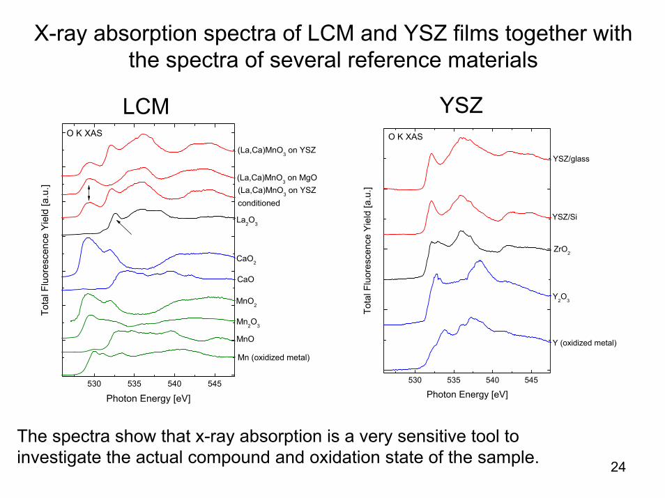
X-ray absorption spectra of LCM and YSZ films together with the spectra of several reference materials
530 535 540 545
(La,Ca)MnO3 on YSZconditioned
MnO2
(La,Ca)MnO3 on YSZ
(La,Ca)MnO3 on MgO
La2O3
CaO2
CaO
Mn2O3
MnO
Mn (oxidized metal)
Tota
l Flu
ores
cenc
e Y
ield
[a.u
.]
Photon Energy [eV]
O K XAS
530 535 540 545
YSZ/glass
YSZ/Si
ZrO2
Y2O3
Y (oxidized metal)
Tota
l Flu
ores
cenc
e Y
ield
[a.u
.]
Photon Energy [eV]
O K XAS
LCM YSZ
The spectra show that x-ray absorption is a very sensitive tool to investigate the actual compound and oxidation state of the sample.

25
X-ray emission spectra of LCM and YSZ films together with those of some reference compounds.
The Y M4,5 emission of the YSZ films is in good agreement with that of the Y2O3 reference.
128 130 132 134 136 138 140
ZrO2
YSZ/glass
YSZ/Si
LCM/YSZ
Y2O3
Y
Nor
mal
ized
Inte
nsity
Emission Energy (eV) (not calibrated)
XESY M
4,5
hν=170 eV
144 146 148 150 152 154 156 158
XESZr M4,5 & Y M4,5
hν=200 eV

26
Relative chemical composition of the probed (La,Ca)MnO3electrode film surfaces
LCM film on La Mn Ca O, peak 1 O, peak 2 C Bi
MgO 5.3% 2.0% 1.7% 16.3% 16.7% 52.4% 5.7%
YSZ not cond 2.6% 7.3% 3.3% 13.6% 21.6% 51.6% 0.0%
YSZ cond 13.1% 3.4% 2.8% 15.8% 18.7% 41.5% 4.7%
Note that this composition is strongly affected by the surface contamination layer, as can be seen in the high relative fraction of C on the surface.

27
Accomplishments: Task 6: Corrosion and Crack Growth Studies of Materials in HIx Environment
• A total of six test systems were constructed to help qualify materials for the different HIx and H3PO4 environments.
• The HI decomposition materials test system replicates the HI gaseous decomposition environment.
• The acid (HIx; HIx + H3PO4) circulating system enabled materials testing in a dynamic environment.
• In FY05/06, a total of 25 materials were screened in HIx at 310°C; Ta and Nballoys met the criteria.
• In FY06/07, additional construction materials for the different environments were identified.
• 13 different materials were tested in the static Iodine Separation (HIx+H3PO4) environment.
• Materials that can handle HIx at high temperature may not be suitable for Iodine Separation.
• 11 candidates were tested in boiling 95 wt% phosphoric acid.• The addition of contaminants (I2, HI) lead to unanticipated corrosion of
materials.• Hastelloys showed the best corrosion performance in the HI decomposition
environment (HI + I2 + H2).• Ta coated components can be an effective means to reduce equipment cost.• Performance of Ta coated components such as fittings and valves were also
evaluated.

28
The acid (HIx; HIx + H3PO4) circulating system
heater
HOT BOX @ 140o C
12”
1.8”
pump
specimen
densephase
light phase
heater
HOT BOX @ 140o C
12”
1.8”
pump
specimen
densephase
light phase
The light phase is pumped into the bottom of the capsule. It rises to the top due to density differenceProcessed and Ta coated parts, stress corrosion and tensile specimens have been tested in this set up
Corrosion behavior can be radically affect by agitationSystem can handle two phase liquids: H3PO4-HI-H2O (light)I2 rich (dense)
0 hr 178 hr
A Ta-10W tube section with a Ta weld

29
Candidate Construction Materials for the Different Environments in HI Decomposition Section
Qualification is based on long-term immersion in regularsettings and that with chemical contaminations
Ta-10W 0.018
Ta-2.5W 0.029
SiC 0.081
Ta 0.113
Iodine Separation
(mpy)
Ta-2.5W 1.361
SiSiC 3.104
H3PO4 Concentration
B2 2.549
C276 13.497
C22 14.438
HI Decomposition
HI Distillation
Ta-10W 0.688
Criteria:Tubing/Valves – 2.95 mpyVessel – 19.7 mpy
Criteria:Tubing/Valves – 2.95 mpyVessel – 19.7 mpy
(mpy)
(mpy)
(mpy)

30
Sample Hours Corr. Rate (mpy)Nb-1Zr (1) 120 -0.92Ta-2.5W 1000 0.029Ta-10W 336 0.045
SiC 120 0.239Mo 160 0.45Ta 336 0.902
Hastelloy B2 336 19.94Nb-7.5Ta 336 22.97Nb-1Zr (2) 120 27.7
Nb 336 38.91Nb-10Hf 336 40.49Zr705 120 91.32C-276 120 139.88C-22 120 147.07
13 different materials tested in the static Iodine Separation (HIx+H3PO4) environment
• Ta, Ta-W and SiC showed no sign of corrosion after test
• Long-term testing up to 1000 hrs has been completed
• Ta alloy bulk components were tested in a system with circulating acid
• Effect of chemical contamination (H2SO4 trace) showed no effect so far
• Ta, Ta-W and SiC showed no sign of corrosion after test
• Long-term testing up to 1000 hrs has been completed
• Ta alloy bulk components were tested in a system with circulating acid
• Effect of chemical contamination (H2SO4 trace) showed no effect so far

31
Materials that can handle HIx at high temperature
Nb alloys showed noticeable corrosion in the HIx + H3PO4mixture at 120°C
0 hr 336 hr scale removed
H3PO4
HIx
Ta alloys are the only metals which can handle the iodine separation acid complexes
0 hr 874 hr 1209 hr
Ta-10W
Nb-10Hf
FY06 Accomplishments: Materials for Iodine Separation

32
11 candidates were tested in boiling 95 wt% phosphoric acid
Based on post test specimen state and corrosion rate, Ta-2.5W, Ag, Cu-Ni and Si-SiC all showed good corrosion resistance in this environmentSiO2 and alumina based ceramics have been severely etched in this acid
hours mpySi-SiC 96 -1.37Ta-2.5W 456 -0.541Ag 336 2.583Cu-Ni 336 0.65B2 336 -4.51
weight gain after test due mainly to a phosphate layer that is attached to the specimen

33
Hastelloys showed the best corrosion performance in the HI decomposition environment (HI + I2 + H2)
hours mpyB-2 1172 2.55C-22 1570 10.70C-276 1220 13.50
0 hr 1570 hrStress corrosion testing of C-22 and C-276 U-bend and C-ring specimens did not show any crack initiation
0 hr 1172 hr
B-2
FY06 Accomplishments: Materials for HI Decomposition

34
Ta coated components such as fittings and valves
0 hr 1160 cycles (88 hr)Most valves parts did not show any sign of corrosion
Valve ball
0 hr 1160 cycles
Valve housing
Testing did reveal incorrect assembly can lead to damage in the Ta coating
Incorrectly installed valve drive bolt
Damaged fitting during installation
FY06 Accomplishments: Testing of Components

35
Accomplishments: Task 7: Ceramic-Based HTHX Development
• Screening of Potential Materials:– Corrosion properties:
• Ceramic materials are resistant to corrosion in high temperature decomposer atmospheres.
• Silicon Carbide & Silicon Nitride form passive, silica (SiO) films that govern corrosion.
• Strength of ceramic materials are insensitive to decomposition temperatures.
• SI Decomposer Design & Scale-up:– Heat exchanger models predict:
• Uniform flow distribution.• 60+% single pass conversion.• 88% effective. • Design S.F > 2.0 for silicon nitride and
silicon carbide.– Fabricated heat exchanger coupons match
experimental results within +5%.
• O2 Chiller Conceptual Design:– 2-stage chiller raises steam for electrolysis
feed while chilling O2 to 75 C.
p g
0.00
200.00
400.00
600.00
800.00
1000.00
1200.00
SN-HP SN-GPS SiC-LS SiC-PS Al2O3-S
Material
Stre
ngth
(MPa
) .
0 hr 100 hr 500 hr 1000 hr
HP-Si3N4 GP-Si3N4 CI-SiC Morgan-SiC Al2O3
HP-
Si3N
4G
P-Si
3N4
CI-
SiC
Mor
gan-
SiC
0 hr 1000 hr
Micro-Channel Pressures
0
200
400
600
8001000
1200
1400
16001800
2000
0.00 0.01 0.02 0.03 0.04 0.05 0.06
Distance (m)
Pres
sure
(Pa)
Water Boiler Plates
Oxygen Pre-Cooler Plates
Hot Oxygen Product
Superheated Steam
Cooled Oxygen
Cold Oxygen
Steam
Water

36
Accomplishments: Task 8: Materials Design and Modeling for C/SiC Compact Ceramic Heat Exchangers
Cold fluid pump trip transient simulation
• Thermal transient response in offset-strip fin region of intermediate heat exchanger solid using effective porous media model
• Roughly a 4 second transient

37
Accomplishments: Task 9: Development of Self Catalytic Materials for Thermo-chemical Water Splitting Using the
Sulfur-Iodine Process
• A series of Alloy 800H plus Pt and Alloy 617 plus Pt alloys in “button” form were melted and characterized from a metallurgical standpoint.
• The catalyst facility is in operation. • The results of this task have shown proof of principle and have shown that the
Pt-added alloys are catalytic.• Five heats each of Alloy 800 H + Pt chemistry, and Alloy 617 + Pt chemistry were
received from Special Metals Inc. Platinum additions were made to the base alloys in nominal amounts of 1 wt%, 2 wt%, and 5 wt% (5 wt% in Alloy 800H only).
• Based on the previous work, Alloy 800H + Pt chemistry materials were etched with a weak version of glyceregia. For Alloy 617 + Pt chemistry materials, stronger version of glyceregia was used. Each material was etched in 1 minute intervals interrupted with ultrasonic cleansing in an ethanol bath in order to periodically monitor microstructure development via optical magnification at 100 X.
• The microstructures in the as cast form were developed via optical microscopy• When compared to the earlier heats of material, which contained an unexpectedly high
carbon content, the new alloys are much cleaner and represent what would be achievable in commercial practice.
• The samples for SEM analysis were intentionally over-etched to facilitate SEM analysis so the exaggerated etching of some of the micrographs is an artifact of this process.

38
As-received Alloy 617 + 1wt% Pt
Alloy 617 + 1 wt% Pt, 254 μmthickness disc cut by Wire EDM for catalytic effectiveness testing

39
Grain, dendrite and precipitate features of cast Alloy 617 + 1 wt% Pt, 200 X.(strong glyceregia - 90 sec; overly etched to reveal dendrite structure inside the grains)

40
Grain boundaries of cast Alloy 800 H + 5 wt% Pt, 5000 X, weak glyceregia - 300 sec
41
Future Work• Task 1: Heat Exchanger Component Design – Continue
numerical analyses for candidate designs, including sulfuric acid boiler, chemical decomposers and oxygen chiller.
• Task 2: Identification and testing of candidate metallic materials for heat exchanger components – Evaluate the performance of Alloy 617 and Haynes 230 at elevated temperatures, perform microstructural evaluation in He environments, characterize creep/stress failure, conduct creep-fatigue testing.
• Task 3: Heat Exchanger Prototype Testing – Investigate insulation materials and design efficient pipeline systems.
• Task 4: Analytical Studies of the Effects of Acid Exposure on Structure Materials – Continue specimen analyses for materials exposed to HI and sulfuric acid.

42
Future Work• Task 6: Corrosion and Crack Growth Studies of Materials in HIx Environment – Study
the effect of chemical environments (HIx + H3PO4 and conc. H3PO4) on the tensile properties of Ta-10W; perform crack growth studies of Hastelloy DCB specimens in the HI gaseous decomposition environment; test the effect of chemical contaminants on Ta-alloys used in Section III; and, identify failure conditions associated with components with Ta cladding
• Task 7: Ceramic-Based High Temperature Heat Exchanger Development – DLR will fabricate Si/SiC HX using molds using UCB mold design. These will be used to demonstrate CVD pyrolitic carbon coating of interior HX surfaces. Analyze the dynamic response of an IHX using liquid salts and conduct a liquid salt viability assessment.
• Task 8: Materials Design and Modeling for C/SiC Compact Ceramic Heat Exchangers Determine corrosion rates and mechanisms for silicon carbide and silicon nitride under a wide range of temperatures and compositions and process boiling conditions. Based on stress models and mechanical properties of ceramics, predict reliability of ceramic components used for heat exchangers. Based on micro-channel designs developed to date, construct a multi-wafer heat exchanger for operational testing.
• Task 9: Development of Self Catalytic Materials for Thermo-chemical Water Splitting Using the Sulfur-Iodine Process – Future work will focus on the characterization of both the catalytic effectiveness of the new alloys as well as the characterization of the electrochemical behavior of these alloys. The new alloys, unlike the original set of alloys melted for this project, exhibit a much cleaner microstructure that is uninfluenced by the excessive carbide precipitation that occurred in the older alloys. This was due to a higher amount of carbon (2-3X the normal specification) in the original heats. The new heats can be expected to perform much better.

43
Summary• Task 1: Heat Exchanger Component Design
– The SO3 decomposition percentage for the off-set strip fin heat exchanger baseline design is 63.81%. The decomposition percentage can be increased with reducing reactants mass flow rate and with increasing channel length and operation pressure.
– Calculation of the processes in the bayonet heat exchanger and decomposer for the baseline design and conditions has been completed. The SO3decomposition percentage obtained by numerical calculations is found to be in the same range as experimental observations. Optimization studies are now ongoing.
– Shell and tube heat exchangers containing a catalytic bed inside the tubes for sulfur trioxide decomposition have a very high calculated decomposition for both counter and parallel flow arrangements (more than 90%).
• Task 2: Identification and testing of candidate metallic materials for heat exchanger components
– High temperature tensile properties of Alloy C-22, C-276, 617, 718, 800H up to 1000 C were evaluated. The nickel-based materials exhibited DSA in specific temperature regime for materials. Yield stress anomaly was also see. At high temperature, not that yield stresses go up.Nb-7.5Ta up to 400 C (for HI decomposition) was evaluated.
– Evaluated metallographic evaluations and fractographic evaluations. A mechanistic understanding of DSA is now established based on activation energy and work hardening index.
– A fracture morphology was used to identify ductile or brittle failure as a function of temperature.
• Task 3: Heat Exchanger Prototype Testing– Prototype test sections were developed to model the
off-set strip fin design.– Isothermal experiments were performed to measure
friction factors.– Heated experiments were performed to measure the
heat transfer coefficient.• Task 4: Analytical Studies of the Effects of Acid Exposure
on Structure Materials– An experimental apparatus was designed to tolerate
the acidic and halogen containing compounds used the sulfur-iodine thermochemical process.
– X-ray photospectroscopy was used to confirm the formation of a silicon dioxide layer on corrosion samples supplied by Ceramatec, Inc. A layer of silica on the surface of the materials may act to blunt surface flaws and lead to an apparent increase in strength, as measured.
• Task 5: Efficiency Improvement and Cost Reduction of Solid Oxide Electrolysis Cells
– Surface sensitive techniques were developed to determine chemical composition and electronic properties. Scanning Probe Microscopy and Spectroscopy provide morphology and local electronic properties with atomic resolution.
– X-ray absorption was found to be a very sensitive tool to investigate the actual compound and oxidation state of the samples.

44
Summary• Task 6: Corrosion and Crack Growth Studies of
Materials in HIx Environment– A total of six test systems were constructed to help
qualify materials for the different HIx and H3PO4environments.
– 13 different materials were tested in the static Iodine Separation (HIx+H3PO4) environment.
– 11 candidates were tested in boiling 95 wt% phosphoric acid.
– The addition of contaminants (I2, HI) lead to unanticipated corrosion of materials.
– Hastelloys showed the best corrosion performance in the HI decomposition environment (HI + I2 + H2).
– Ta coated components can be an effective means to reduce equipment cost. Performance of Ta coated components such as fittings and valves were also evaluated.
• Task 7: Ceramic-Based High Temperature Heat Exchanger Development
– Ceramic materials are resistant to corrosion in high temperature decomposer atmospheres. Silicon Carbide and Silicon Nitride form passive, silica (SiO) films that govern corrosion. Strength of ceramic materials are insensitive to decomposition temperatures.
– Fabricated heat exchanger coupons match experimental results within +5%.
• Task 8: Materials Design and Modeling for C/SiC Compact Ceramic Heat Exchangers
– A porous media model was developed to study the thermal transient response in the offset-strip fin region of IHX solid. Roughly a 4 second transientwas determined.
• Task 9: Development of Self Catalytic Materials for Thermo-chemical Water Splitting Using the Sulfur-Iodine Process
– A series of Alloy 800H plus Pt and Alloy 617 plus Pt alloys in “button” form were melted and characterized from a metallurgical standpoint.
– The results of this task have shown proof of principle and have shown that the Pt-added alloys are catalytic.
– When compared to the earlier heats of material, which contained an unexpectedly high carbon content, the new alloys are much cleaner and represent what would be achievable in commercial practice.


![UNLV Presentation [FREBERG]](https://img.dokumen.tips/doc/110x75/546de196b4af9f892c8b55e5/unlv-presentation-freberg.jpg)